the Creative Commons Attribution 4.0 License.
the Creative Commons Attribution 4.0 License.
 | 08 Dec 2021
Horizontal vibration response analysis of ultra-high-speed elevators by considering the effect of wind load on buildings
Guangjiu Qin
Shuohua Zhang
Hao Jing
At present, the wind-induced vibration effects of super-high-rise buildings caused by wind loads can no longer be ignored. The wind-induced vibration effect of super-high-rise buildings will inevitably cause the vibration of ultra-high-speed elevators. However, for the study of the vibration characteristics of ultra-high-speed elevators, the wind-induced vibration effect of the ultra-high-speed elevator is often ignored. Based on Bernoulli–Euler theory, the forced vibration differential equation of elevator guide rail was established, and the vibration equation of elevator guide shoe and car was established by using the Darren Bell principle. The coupled vibration model of the guide rail, guide shoes, and car can be obtained through the relationship of force and relative displacement among these components. Based on the model, the effects of wind pressure and building height on the horizontal vibration of the ultra-high-speed guideway and passenger comfort were analyzed. The results showed that the influence of the wind load on the vibration of ultra-high-speed elevator can no longer be disregarded, and the maximum horizontal vibration acceleration of the guide rail is positively correlated with the height of building. The vibration acceleration of the same height rail increases with the increase in wind pressure. The vibration dose values (VDVs) increase with the increase in wind pressure and building height, respectively.
- Article
(2632 KB) - Full-text XML
- BibTeX
- EndNote


Ultra-high-speed elevators are gradually used in super-high-rise buildings. However, super-high-rise buildings have the characteristics of low natural frequency and large flexibility. This kind of building is a typical wind-sensitive structure (Xu et al., 2015). The vibration deformation of super-high-rise buildings under wind load will inevitably cause the vibration deformation of an elevator guide rail installed in a super-high-rise building (Deng et al., 2015; Feng et al., 2012; Zhi et al., 2017). The vibration deformation of the guide rail is transmitted to the car through the guide shoe, and the vibration response of the car can also act on the guide rail through the guide shoe. Therefore, the guide rail, guide shoe, and car are transformed into a coupling system. In this coupling state, the wind load can no longer be ignored for the vibration of ultra-high-speed elevators in super-high-rise buildings. At present, the number of super-high-rise buildings is increasing. Therefore, we should study the vibration mechanism of ultra-high-speed elevators under wind loads, based on the vibration model of the elevator coupling system. In addition, we should understand the operation law of the ultra-high-speed elevator in order to improve the operation quality of the elevator.
Elevator vibration is generally divided into horizontal and vertical vibrations. The human body is more sensitive to horizontal vibration than to vertical vibration (Chen et al., 2016). In addition, the horizontal vibration of the elevator is proportional to its speed (Rao et al., 2016). Therefore, this paper analyzes the horizontal vibration of ultra-high-speed elevator under wind load. Yokota et al. (1987) analyzed the vibration characteristics of an elevator and building system through a vibration exciter test and introduced several measures to reduce the vibration of elevator car. Li et al. (2002) simplified the guide shoe system as a spring damping system, established a 2 DOF (degrees of freedom) horizontal vibration model of the elevator car, simulated the vibration model based on the analysis of the incentive of elevator guide, and provided an effective simulation method for the horizontal vibration of an elevator. Fu et al. (2003) obtained the horizontal vibration differential equation, used the conversion between the local and global coordinate systems, discussed the disturbance model of the guide rail, compared the acceleration response of the elevator under the sine, triangle, pulse, and step disturbances, and concluded that the step disturbance of the guideway would cause a large horizontal vibration. Feng (2007) established the spatial dynamic model of elevator horizontal vibration and simulated the vibration model of the car system by considering the measured rail excitation as the input signal. Mei et al. (2009) established a three-dimensional rolling contact model, considering the nonlinear-rate-dependent characteristics of a rubber shoe liner, and established a mathematical model of interference on a smooth excitation for the guide rail of a rolling guide shoe after considering the roundness deviation of the guide roller. Yin et al. (2011) transformed the influencing factor of the horizontal vibration of elevator car (e.g., rail unevenness, rail bending, guide shoe defects, etc.) into the force of the guide rail on the guide shoe and analyzed the horizontal vibration of a high-speed elevator car. In these studies, the guide rail is used as an external excitation to analyze the horizontal vibration of the elevator car without considering the effect of wind load and the coupling between the guide rail, guide shoe, and car.
Li et al. (2005) established a coupling dynamic model including the elevator frame, roller, and guide rail, based on the wheel rail contact stiffness, without considering the contact damping between the roller and guide rail and the contact stiffness between the roller and car. Guo et al. (2011) established the dynamic coupling model of the car, guide shoe, and guide rail of an elevator and studied the nonlinear factors between the guide shoe and guide rail. Zhu et al. (2013) established the vibration model of an elevator coupling system based on the vibration model of the car and the guide rail, using the force relationship between the guide shoe and the guide rail; thereafter, they studied the vibration of the coupling system under earthquake excitation. A close examination of the preceding studies reveals the limitations of the analytical solutions of previous research. However, the coupling model between the various systems of an elevator has been obtained because the wind load factor was disregarded.
The continuous construction of high-rise buildings has led scholars to study the wind-induced response of these structures. Li et al. (2007) and Fu et al. (2008, 2012) measured the top wind characteristics and wind-induced vibration response of several high-rise buildings in Guangdong, China, and obtained extensive field measured data. Kijewski and Prinia (2007) and Bashor et al. (2012) conducted field tests on the dynamic characteristics of several buildings in Boston and Chicago, USA, and studied the time frequency analysis and modal identification of the acceleration response. Huang et al. (2017) used aerodynamic elastic mechanics to study the aerodynamic interference effect between high-rise buildings, which provided beneficial information for avoiding or reducing vortex resonance. Huang et al. (2015) used the three-scale perturbation method to study the horizontal vibration of elevator cables. They explained that the upper part of the elevator cable was subjected to a type of sinusoidal excitation due to the horizontal movement of a building. Moreover, the self-resonance phenomenon of the elevator system was further studied by the aforementioned researchers. The preceding study details the vibration response of buildings under wind load. However, the horizontal vibration response analysis of ultra-high-speed elevator, considering the influence of wind load on buildings, has not been carried out yet.
In view of the above problems, the current study aims to establish a complete coupling vibration model of an elevator system, introduce the wind-induced vibration theory of super-high-rise building structure, and investigate the influence of building height and wind pressure on the horizontal vibration of ultra-high-speed elevator rails fixed in super-high-rise buildings under wind-induced vibration conditions. The current analysis can be a step forward toward designing the vibration damping of ultra-high-speed elevators to enhance riding comfort.
As the structure of ultra-high-speed elevator is complex, and it is not conducive to theoretical research, the following assumptions and simplifications are made in this paper:
-
the car body and frame have a rigid connection between them;
-
the mass center of the car coincides with its geometric center;
-
the car and roller are simplified as a mass spring damping system because the movement of the car relative to the roller and the roller relative to the guide rail is considerably small in the normal rail surface;
-
the structure and parameters of each roller are the same; and
-
the guide rails of one side are simplified as a multi-span, elongated, straight continuous beam.
The horizontal vibration of an elevator system includes its lateral vibration (y direction) and front and back vibration (x direction). The lateral vibration is similar to the front and rear vibration dynamic models, and the modal frequencies are similar, so they are often studied separately. In the coupling state of guide rail, guide shoe, and car system, the vibration of guide rail has a great influence on the vibration of elevator system. Therefore, this research mainly studies the horizontal vibration of guide rails under the wind load acting on a building (i.e., the horizontal vibrations of the guide rails and what follows in the passage are vibrations in the y direction). Figure 1 shows the horizontal vibration model of an ultra-high-speed elevator considering wind-induced vibration of buildings.
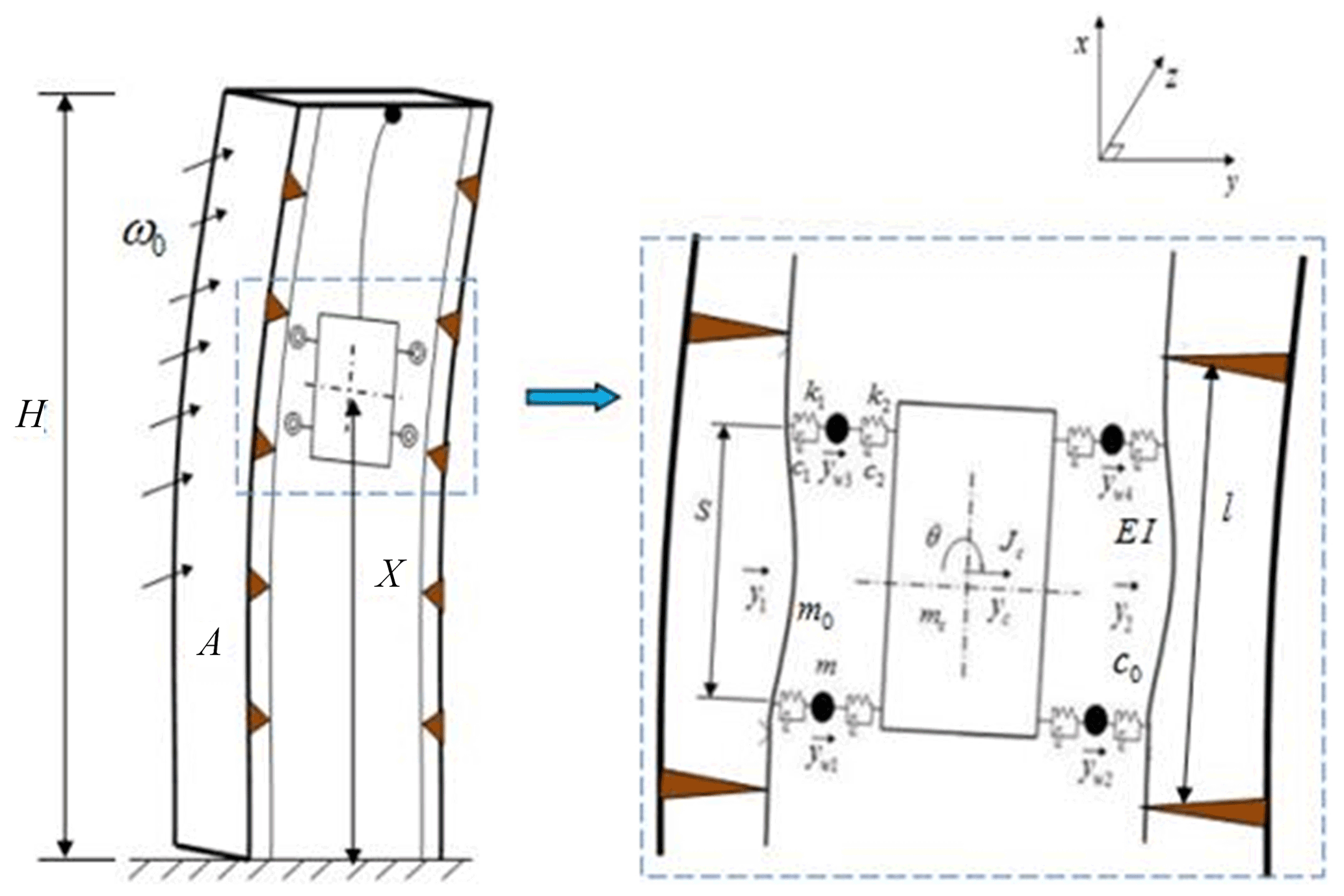
Figure 1 shows that H is total height of the super-high-rise building, ω0 is the basic wind pressure for a 50 year return period, A is the windward area of the building, X is the elevator lift height, l is the length of guide rail, m0 is the mass of the guide rail unit length, EI is the bending stiffness of the guide rail, and c0 is the damping of the guide rail. In addition, S is the distance in the x direction of the upper and lower rollers, and y1 is the elastic deformation of guide rail 1 at t time, y2 is the elastic deformation the moment of guide rail 2 at t time. yw1, yw2, yw3, and yw4 are the horizontal displacements of rollers 1, 2, 3, and 4, respectively. m is the mass of the roller, k1 is the contact stiffness between the roller and guide rail, c1 is the contact damping between the roller and guide rail, k2 is the connection stiffness between the roller and car system, c2 is the connection damping between the roller and car system, yc and θ are the horizontal and angular displacements of the car system, respectively, mc is the quality of the car system, and Jc is the moment of inertia of the car system.
2.1 Horizontal vibration model of the ultra-high-speed elevator car, guide shoe, and guide rail coupling system
The guide rails are fixed on a building and keep a predetermined distance from the rail support. Because the horizontal deflection of the guide rail is much less than the length of the guide rail, we regard the guide rail as Euler beam. Bernoulli–Euler theory indicates that, under the coupled interaction of the guide shoe and rail, the forced vibration differential equations of guide rail 1 and guide rail 2 can be expressed as follows:
For the car system and roller, the unevenness of the rail surface is an important excitation source that triggers their vibration. When considering the wheel rail coupling, the rail surface roughness will affect the vibration of the rail itself, which shows the influence on the wheel rail contact force. To conveniently study the relationship between the rail surface roughness and guide rail vibration, the surface roughness of guide rails 1 and 2 is assumed to be the same at the same lifting height. We set the surface roughness value of the guide rail at the contact point between the lower roller and guide rails 1 and 2 to r(s1(t)). Meanwhile, the surface roughness value of the upper roller and guide rails 1 and 2 is r(s2(t)). The contact force can be expressed as follows:
The damping force between the car system and roller is determined by the instantaneous horizontal velocity, rotational angular velocity of the car system, and instantaneous horizontal velocity of the wheel. The elastic force between the car system and roller also depends on the instantaneous level of the car system displacement, rotation angular displacement, and momentary displacement of the roller. Considering that the outer edge of the roller is damping rubber and the relative displacement between the roller and the guide rail is small, the roller is simplified as a mass spring damping system, which is connected with the guide rail through the spring and damper. The dalangel principle is used to establish the motion equations of the four rollers as the following equations:
Similarly, considering that there is damping rubber between the car and the frame, damping spring between the shoes, and the relative displacement between the car and the roller is small, the connection mode between the car and the roller is simplified to a spring and damping system. The car system is regarded as a rigid body, and its horizontal movement includes translation along the y axis and rotation around the centroid. The dalangel principle is used to establish the following differential equation for the overall horizontal and rotational displacements of the car system under the coupling of the car system and roller:
2.2 Rail vibration model considering the wind-induced vibration of super-high-rise buildings
To determine the horizontal vibration response of a super-high-speed elevator under wind load, it is necessary to study the action law of wind load on super-high-rise buildings.
The corresponding super-high-rise building may reach the maximum wind-induced vibration at this location when the ultra-high-speed elevator reaches any lifting height. Therefore, to explore the influence of wind-induced vibration on the vibration of ultra-high-speed elevator systems, only the maximum wind-induced vibration response at each height of super-high-rise building is considered.
Referring to the research results of building structure (Chinese Standard, 2012; Chen, 2007), the maximum wind-induced vibration response corresponding to the height of super-high-rise building is obtained.
The peak values of a super-high-rise building wind-induced vibration acceleration (downwind) is provided as follows:
where ξ is the pulsation increase coefficient, γ is the deformation coefficient, μ is the variation coefficient of the wind pressure height, ω is the basic wind pressure for a 10-year return period, such that ω=0.75ω0, M is the building mass, and φz is the height coefficient, such that , where Z is the super-high-rise building height position, and its value is equal to the elevator lift height X.
This study just considers the vibration response of the guide rail under the maximum wind-induced vibration of the building and only considers the direction of the building vibration in the same direction as the horizontal vibration direction of the guide rail. Accordingly, the vibration response of the guide rail under the wind-induced vibration of super-high-rise buildings can be expressed as follows:
where is the acceleration response of the elevator guide rail vibration that considers the wind-induced vibration of the super-high-rise building, is the acceleration response of the elevator guide rail under a coupling system, and a is the wind-induced vibration acceleration response of the super-high-rise building.
Any reasonable displacement of the structure can be represented by the superposition of the structure individual modes having corresponding amplitudes. This study uses the mode decomposition method to transform the partial differential equation of the guide rail into an ordinary differential equation as in the following equation:
where qij(t) is the generalized mode coordinates of the guide rail, is the vibration mode function of the guide rail, and nl is the total length of one side of the guide rail.
To obtain the n order general coordinate motion equation of the guide rail, we substitute Eq. (8) into Eqs. (1) and (2) and then the two sides of Eqs. (1) and (2) are multiplied by αi(x) and integrated on the [0, l] interval. The i order general coordinate motion equation of the guide rail can be obtained by the orthogonality of the mode shapes as in the following equations:
where k0 is the calculation stiffness of the guide rail under a generalized coordinate, and fi1 and fi2 are the generalized load vectors of guide rails 1 and 2, respectively.
We consider the generalized coordinate motion in Eqs. (10) and (11) for the guide rail under the coupling action and the motion Eqs. (3–6) for the car and rollers. After the consolidation, the coupling kinetic equation of the system can be merged into the following form:
where M, C, and K are the mass, damping, and stiffness matrices, respectively, of the coupled system, is the generalized displacement vector of the system, and {F(t)} is the generalized load vector of the system that considers the wheel and rail to be preloaded.
The coefficient of the system dynamic equilibrium Eq. (11) changes with the change in the position of the guide shoe on the guide rail; thus, the equation comprises second-order differential equations with time-varying coefficients. Such a time-varying coefficient differential equation group can be solved generally only through a step-by-step numerical method (Chao et al., 2017). Given the influence of the structural parameters on the dynamic characteristics of the guide rail and the nonlinearity of the equation group, a step-by-step integral program with a discrete variable is compiled based on the incremental method to solve the system (Mohammad et al., 2016; Luis et al., 2017).
4.1 Calculation parameter analysis and simulation method
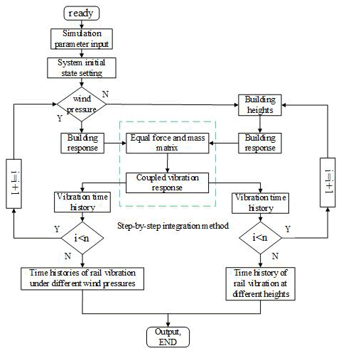
The large-span discrete values of the wind pressure are selected to completely investigate the influence of the wind pressure on the vibration of the ultra-high-speed elevator. Similarly, this study also selects the large-span discrete values of the building height. The ultra-high-speed elevator, with a rated running speed of 20 m s−1, is the research object for the simulation. Table 1 shows the main input parameters of the simulation. The selection of simulation parameters in Table 1 is based on the actual elevator.
We compile the calculation program based on the dynamic model of the car wheel rail coupling system and wind-induced vibration model of the super-high-rise building. Figure 2 shows the calculation process.
4.2 Simulation results analysis
The horizontal vibration model and ultra-high-speed elevator coupling vibration model established in Sect. 2 are used as the basis to perform the simulation experiment, using the analysis method discussed in Sect. 3.1. We keep the specific parameters in Table 1 unchanged, only change the studied parameters, and simulate different working conditions. The results are as follows.
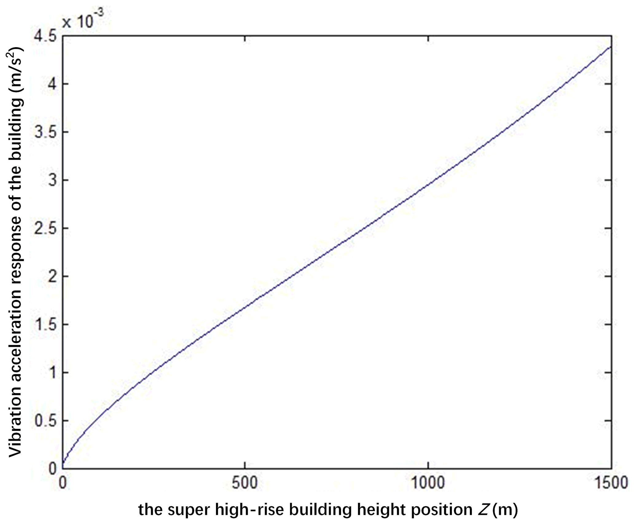
4.2.1 Maximum vibration acceleration of the building
Figure 3 shows that, by using a 1500 m super-high-rise building as an example, the maximum vibration acceleration of such building is obtained with the height. Evidently, as the height increases, the maximum vibration acceleration of the building increases as well. The maximum vibration acceleration of the building is approximately linear with the height.
4.2.2 Effect of wind pressure on the vibration response of the guide rail
Figure 4 shows the following scenarios:
-
The guide rail vibration acceleration increased significantly when considering the wind pressure.
-
The vibration acceleration of the rail tends to increase as the lifting height increases, due to the influence of the wind-induced vibration of the building. The reason for this phenomenon is the maximum wind-induced vibration of the building at different heights. Figure 1 shows that the maximum vibration acceleration of the building is proportional to the height.
-
The comparison of the vibration curve of the guide rail under different wind pressures shows that the guide rail vibration acceleration increases with the increase in the basic wind pressure in the 10-year period at the same height position. Under the condition of high wind pressure, the change rate of the vibration acceleration of the guide rail with the lifting height is greater.
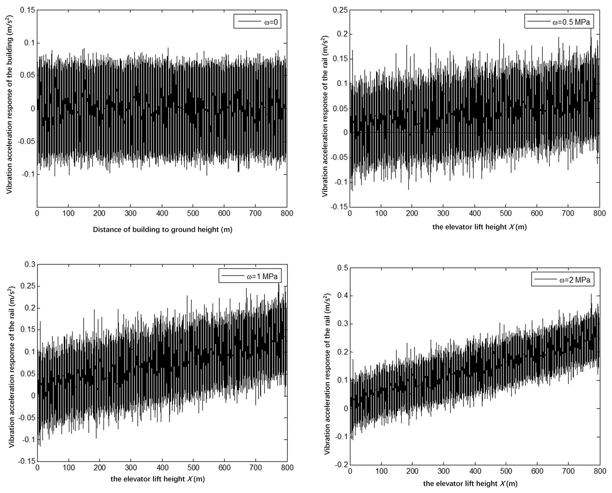
Figure 4Vibration acceleration curve of the guide rail under different basic wind pressure conditions.
4.2.3 Influence of the building height on the vibration response of the guide rail
Figure 5 shows the following scenarios:
-
The comparison of the vibration curve of the guide rail under various building heights (i.e., 500, 800, 1200, and 1500 m) shows that the maximum vibration acceleration of the rail appears near the highest point of the lifting height.
-
As can be seen from Fig. 5, the vibration acceleration of the guide rail tends to increase with an increase in the lifting height. This trend is particularly evident at the building height of 1500 m. The vibration acceleration increased by 4.5 times from the vibration acceleration peak of 0.1 m s−2 for the guide rail at the bottom of the building to that of 0.45 m s−2 for the guide rail at top of the building.
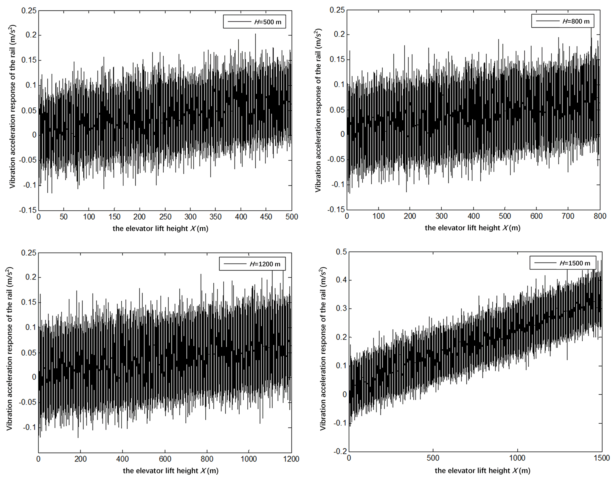
Figure 5Vibration acceleration curve of the elevator guide rail under different building heights.
4.2.4 Influence of wind pressure and building height on passenger comfort
The whole process of the car operation is selected as the research object, and the vibration dose value (VDV) is used to detect the passenger comfort (British Standard Guide, 1987). The VDV is defined as follows:
where T is the duration of the vibration signal, and is the acceleration of the vibration signal after the weighting of the frequency meter. The VDVs of the elevator under different wind pressure and building height are calculated, respectively, as shown in Table 2.
Table 2The VDVs of elevator under situations with different wind pressure and building height.
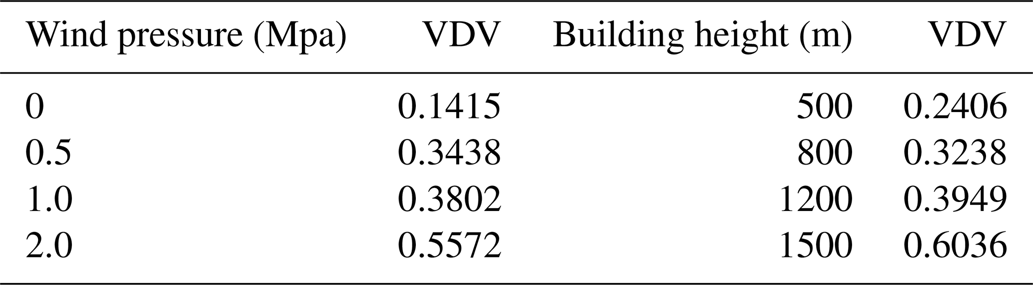
As can be seen from the Table 2, the VDVs increase with the increase in wind pressure and building height, respectively. When the wind pressure reaches 2 Mpa, the VDVs suddenly increase from 0.3802 to 0.5572, which is an increase of 46.55 %. When the building height reaches 1500 m, the VDVs suddenly increase from 0.3949 to 0.6036, which is an increase of 52.85 %. This shows that excessive wind pressure and building height will greatly reduce the comfort of passengers.
This study started from the two aspects of wind pressure and super-high-rise building height and expounded the effect of a super-high-rise building wind-induced effect on the vibration of the ultra-high-speed elevator guide rail. The following conclusions are drawn:
-
The vibration acceleration of the guide rail is positively correlated with the wind pressure of the building. Under certain other conditions, with the increase in the wind pressure, the change rate of the vibration acceleration of the guide rail increases gradually during the whole process of the car operation. Therefore, the local climate factors should be considered in the installation of an ultra-high-speed elevator.
-
The vibration acceleration of the guide rail is positively correlated with the lifting height. When the building height reaches a certain value, the flexibility of the building increases, the sensitivity to wind becomes considerably prominent, and the change rate of the vibration acceleration of the guide rail becomes larger.
-
The VDVs increase with the increase in wind pressure and building height, respectively. Excessive wind pressure and building height will have a severe impact on passenger comfort.
The results showed that the effect of the wind load on the vibration of an ultra-high-speed elevator can no longer be disregarded. For the first time, the influence of the wind load on a super-high-rise building in the field of a building structure is introduced into the vibration of an ultra-high-speed elevator coupling system. The simulation results verify the vibration characteristics of super-high-rise buildings as wind sensitive structures and provide a theoretical reference for the consideration of the wind-induced vibration of super-high-rise buildings during the design and installation processes.
All data included in this study are available upon request from the corresponding author. Please note that some of the data and codes are confidential (and fall under the umbrella of the protection of trade secrets) and cannot be made publicly available.
GQ conceived the idea, developed the method, performed experiments and simulations, and wrote the majority of the paper. SZ and HJ supervised and structured the paper. SZ edited the paper, and HJ corrected the paper.
The contact author has declared that neither they nor their co-authors have any competing interests.
Publisher's note: Copernicus Publications remains neutral with regard to jurisdictional claims in published maps and institutional affiliations.
This paper was edited by Dario Richiedei and reviewed by Xabier Arrasate and one anonymous referee.
Bashor, R., Bobby, S., and Kijewskj, C. T.: Full-scale performance evaluation of tall buildings under wind, J. Wind Eng. Ind. Aerod., 104, 88–97, 2012.
British Standard Guide: BS 6841, Measurement and evaluation of human exposure to whole-body mechanical vibration and repeated shock, BSI, London, 1987.
Chen, F.: Theoretical analysis and software development of wind-induced responses on buildings and structures, Institute of Building Structures China Academy of Building Research, Beijing, 2007.
Chen, J.: Performance Analysis of Horizontal Vibration in High-speed Elevator and Design Optimization of Guidance System and its Application, Zhejiang University, Zhejiang, 2016.
Chao, Y. T. and Zhu, B. Y.: Generalized Multi-step Explicit Integral Algorithm in Structural Dynamics, Journal of Southwest Jiao Tong University, 1, 133–140, 2017.
Chinese Standard: GB50009-2012, Load code for the design of building structures, CN-GB, 2012.
Deng, T., Yu, X. F., and Xie, Z. N.: Aerodynamic measurements of across-wind loads and responses of tapered super high-rise buildings, Wind Struct., 21, 331–352, 2015.
Feng, R. Q., Yan, G. R., and Ge, J. M.: Effects of high modes on the wind-induced response of super high-rise buildings, Earthq. Eng. Eng. Vib., 11, 427–434, 2012.
Feng, Y. H.: The Modeling and Simulation of Horizontal Vibrations for High-speed Elevator, Journal of Shanghai Jiaotong University, 41, 557–560, 2007.
Fu, J. Y., Li, Q. S., and Wu, J. R.: Field measurements of boundary layer wind characteristics and wind induced responses of super-tall buildings, Eng. Struct., 96, 1332–1358, 2008.
Fu, J. Y., Wu, J. R., and Xu, A.: Full-scale measurements of wind effects on Guangzhou West Tower, Eng. Struct., 35, 120–139, 2012.
Fu, W. J. and Zhu, C. M.: Horizontal vibration modeling and dynamic response analysis of high speed elevator, Machine Design & Research., 19, 65–67, 2003.
Guo, K. J.: Research on Vibration Modeling and dynamics simulation of sliding guidance system, Journal of Vibration and Shock, 28, 70–73, 2011.
Huang, D. M., Zhu, L. D., and Ding, Q. S.: Aeroelastic and aerodynamic interference effects on a high-rise building, J. Fluid. Struct., 3, 355–381, 2017.
Huang, D. M., Zhu, L. D., and Ding, Q. S.: On a cascade of autoresonances in an elevator cable system, Nonlinear Dynam., 6, 1613–1630, 2015.
Kijewski, C. T. and Prinia, J. D.: Dynamic behavior of tall buildings under wind: insights from full-scale monitoring, Struct. Des. Tall Spec., 16, 471–486, 2007.
Li, D. D.: High frequency vibration analysis of wheel rail coupling in elevator, Shanghai international industry exposition, the third Shanghai engineering and vibration science and Technology Forum, November 2005, Shanghai, 2005.
Li, L. J., Li, X. F., Zhang, G. X., and Li, Z.: Horizontal vibration model of elevator car, Hoisting and Conveying Machinery, 5, 3–5, 2002.
Li, Q. S., Xiao, Y. Q., and Fu, J. Y.: Full-scale measurements of wind effects on the Jin Mao building, J. Wind Eng. Ind. Aerod., 95, 445–466, 2007.
Luis, F., Paullo, M., and Deane, R.: Continuation method with combined restrictions for nonlinear STRUCTURE Analysis, Finite Elem. Anal. Des., 130, 53–64, 2017.
Mei, D. Q.: Vibration Analysis of High-speed Traction Elevator Based on Guide Roller-rail Contact Model, J. Mech. Eng., 45, 265–270, 2009.
Mohammad, R. P. and Hossein, E.: Mixing dynamic relaxation method with load factor and is placement increments, Comput. Struct., 168, 78–91, 2016.
Rao, Y.: Study and Application on Multi-directional Coupling Vibration Modeling and Design of Vibration Reduction of High-speed Elevator Traction System, Zhejiang University, Zhejiang, 2016.
Xu, Z. N., Xie, M., and Gu, J. R.: A new method for dynamic parameters identification of a model-balance system in high-frequency force-balance wind tunnel test, J. Vibroeng., 17, 2609–2623, 2015.
Yin, J. C. and Rui, Y. N.: Research on horizontal dynamic characteristics and Simulation of highspeed elevator with multi degree of freedom, Journal of Machine Design, 28, 70–73, 2011.
Yokota, S. and Liu, J. N., Huang, B.: Vibration analysis of elevator system, Hoistign and Conveying Machinery, 8, 57–62, 1987.
Zhi, L. H., Yu, P., and Tu, J. W.: A Kalman filter based algorithm for wind load estimation on high-rise buildings, Struct. Eng. Mech., 64, 449–459, 2017.
Zhu, M., Zhang, P., Zhu, C., and Jin, C.: Seismic response of elevator and rail coupled system, Earthq. Eng. Eng. Vib., 4, 183–188, 2013.