the Creative Commons Attribution 4.0 License.
the Creative Commons Attribution 4.0 License.
 | 24 Nov 2021
Analysis and compensation control of passive rotation on a 6-DOF electrically driven Stewart platform
Qitao Huang
Peng Wang
Bowen Li
Qingjun Yang
With the development of motor control technology, the electrically driven Stewart platform (EDSP), equipped with a ball screw or lead screw, is being widely used as a motion simulator, end effector, and vibration isolator. The motor drives the lead screw on each driven branch chain to realize 6-DOF motion of the moving platform. The control loop of the EDSP adopts the rotor position as a feedback signal from the encoder or resolver on the motor. When the moving platform of the EDSP performs translational or rotational motion, the lead screw on each driven branch chain passively generates a relative rotation between its screw and nut in addition to its original sliding motion. This type of passive rotation (PR) of the lead screw does not disturb the motor; hence, it cannot be detected by the position sensor attached to the corresponding motor. Thus, the driven branch chains cause unexpected length changes because of PR. As a result, the PR generates posture errors on the moving platform during operation. In our research, the PR on the EDSP was modeled and analyzed according to the geometry configuration of EDSP. Then, a control method to compensate for the posture errors caused by the PR was proposed. Finally, the effectiveness of the analysis process and compensation control method were validated; the improvement in pose accuracy was confirmed both by simulation and experiments.
- Article
(7496 KB) - Full-text XML
- BibTeX
- EndNote


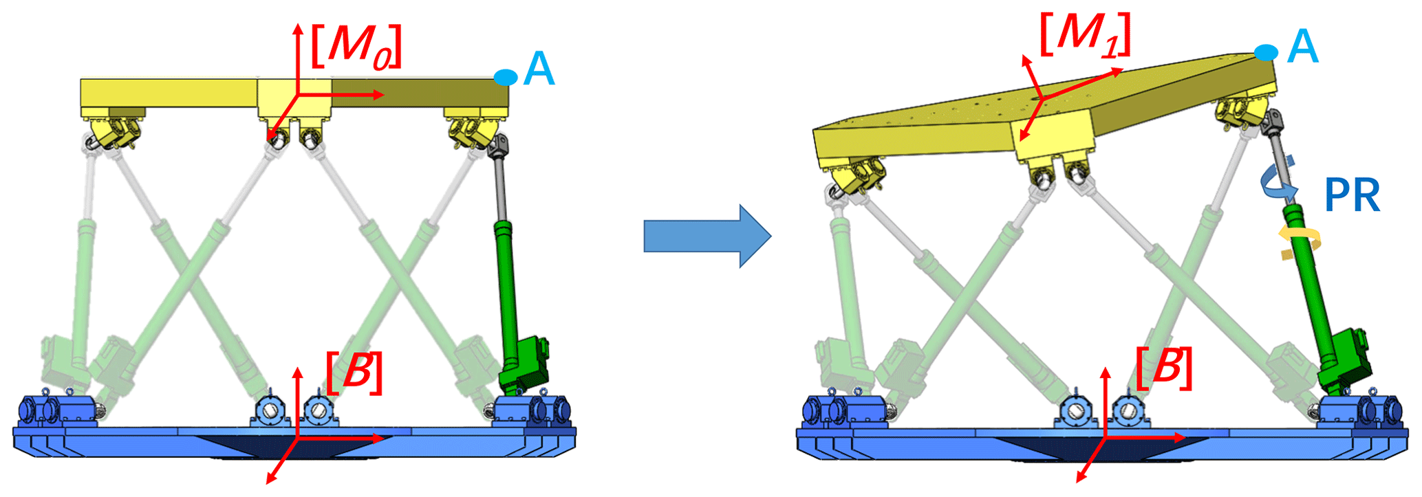
Owing to their advantages of high load capacity and accuracy, parallel manipulators are widely used in applications such as motion simulators, end effectors, and vibration isolators (Huang et al., 2005; Li et al., 2018; Kim et al., 2017). With the advancements in drive motor technology, the electrically driven Stewart platform (EDSP), equipped with a motor and ball screw or lead screw as the drive unit, has attracted growing attention. In the EDSP, each Hooke's joint with 2 degrees of freedom (DOF) connects each driven branch chain to the base platform and moving platform. Each driven branch chain contains one lead screw, which provides translational motion along its axis to drive the moving platform with 6-DOF motion. In addition to the linear motion, the lead screw can also rotate around the axis between the screw and the nut. This 2-DOF motion capability makes the lead screw perform like a cylindrical pair on the driven branch. However, owing to the mechanical structure of the lead screw, its linear displacement is directly proportional to the angle of rotation. In the EDSP, when the moving platform is driven by the lead screw, it passively rotates relative to the nut under the action of the moving platform's carrier motion, through the Hooke's joint. This PR would cause unexpected linear motion on the lead screw and would generate a posture error related to the moving platform, reducing the motion accuracy of the EDSP. Furthermore, this PR occurs only on the lead screw and is not detected by the encoder on the motor. Thus, the posture error caused by the PR will be completely ignored in the control system. The inaccuracy caused by the PR has restricted the use of EDSP in high-precision cases. Thus, this type of motion error on the EDSP must be analyzed and compensated for to achieve higher accuracy.
The improvement in the accuracy of the Stewart platform has been a research area of high interest. Zhang et al. (2019) provided a simple and flexible method for the calibration of parallel manipulators to improve the position accuracy using a backpropagation (BP) neural network. An indoor GPS system has also been applied to assess the actual pose of the moving platform and perform online correction of pose error (Porath et al., 2020; Liu, 2016). Ding et al. (2013) proposed a novel active preload control method to satisfy the requirement of high precision. Jáuregui-Correa et al. (2015) analyzed the origin of errors due to manufacturing and assembling processes, which affect the pose accuracy of a robot. They presented two methods for assessing pose accuracy in parallel manipulators and applied them to estimate the accuracy of a high-precision Stewart platform. Wu et al. (2019) used the piecewise integral reset PI (proportion–integration) controller as a position loop controller to ensure the precision of trajectory tracking and to speed up the stabilization of the system. Li et al. (2018) proposed a dual quaternion approach to derive the dimensionally homogeneous Jacobian matrix of a Stewart platform. This matrix was then used in the optimal design of a six-axis vibration isolator to achieve minimum kinematic coupling in its working configuration.
Compensation is a common method used in control strategy to improve motion performance. Garagi and Srinivasan (2002) designed two robust adaptive control algorithms for friction compensation in high-performance parallel manipulator tools. Similarly, Ahmad et al. (2013) evaluated different friction models and compared their friction compensation effects on the Stewart platform. Wu et al. (2009) proposed a novel adaptive fuzzy trajectory tracking algorithm for a Stewart platform-based motion platform to compensate for path deviation and controller performance degradation because of the actuator torque limit. In the research field of medical robots, Kim et al. (2017) used impedance and admittance control algorithms to compensate for respiratory motion during robotic needle insertion. Hernandez et al. (2014) presented numerical results regarding the beneficial effects of error compensation in the legs, as well as in the end effector. In the same study, a numerical methodology was introduced for error compensation modeling and numerical simulation of its effects. An iterative approach was used in the inverse kinematic solution to compensate for the offset error (Chen et al., 2002). Du et al. (2019a) analyzed the calculation of passive rotation in different kinds of joints with 2-DOF in rotation. In addition to this, Du et al. (2016, 2019b) also calculated the angle of passive rotation caused by rotational joints in the parallel manipulator. However, their research still stays in the analysis stage and lacks the support of simulation and experiments.
In this study, precise modeling of PR in EDSP and a compensation control strategy are provided. The calculation and analysis of PR are presented in Sect. 2. A control strategy with a compensation function is described in Sect. 3. Section 4 presents the details of simulation with two control strategies. Section 5 covers the design of experiment and its implementation. The simulation and experimental results verify the correctness of analysis of PR and the effective pose accuracy improvement, as provided by the compensation control.
2.1 Electrically driven Stewart platform (EDSP)
An EDSP consists of a moving platform, a base platform, six driven branch chains, and 12 spherical joints or Hooke's joints connecting each chain to the two platforms, as shown in Fig. 1. Compared to spherical joints, Hooke's joints have a relatively larger workspace and higher payload capacity. Consequently, in most situations, Hooke's joints are assembled on the EDSP. In this study, Hooke's joint was chosen for the experiments. Each branch chain includes a motor, a gearbox, and a lead screw, acting as an actuator of the EDSP.
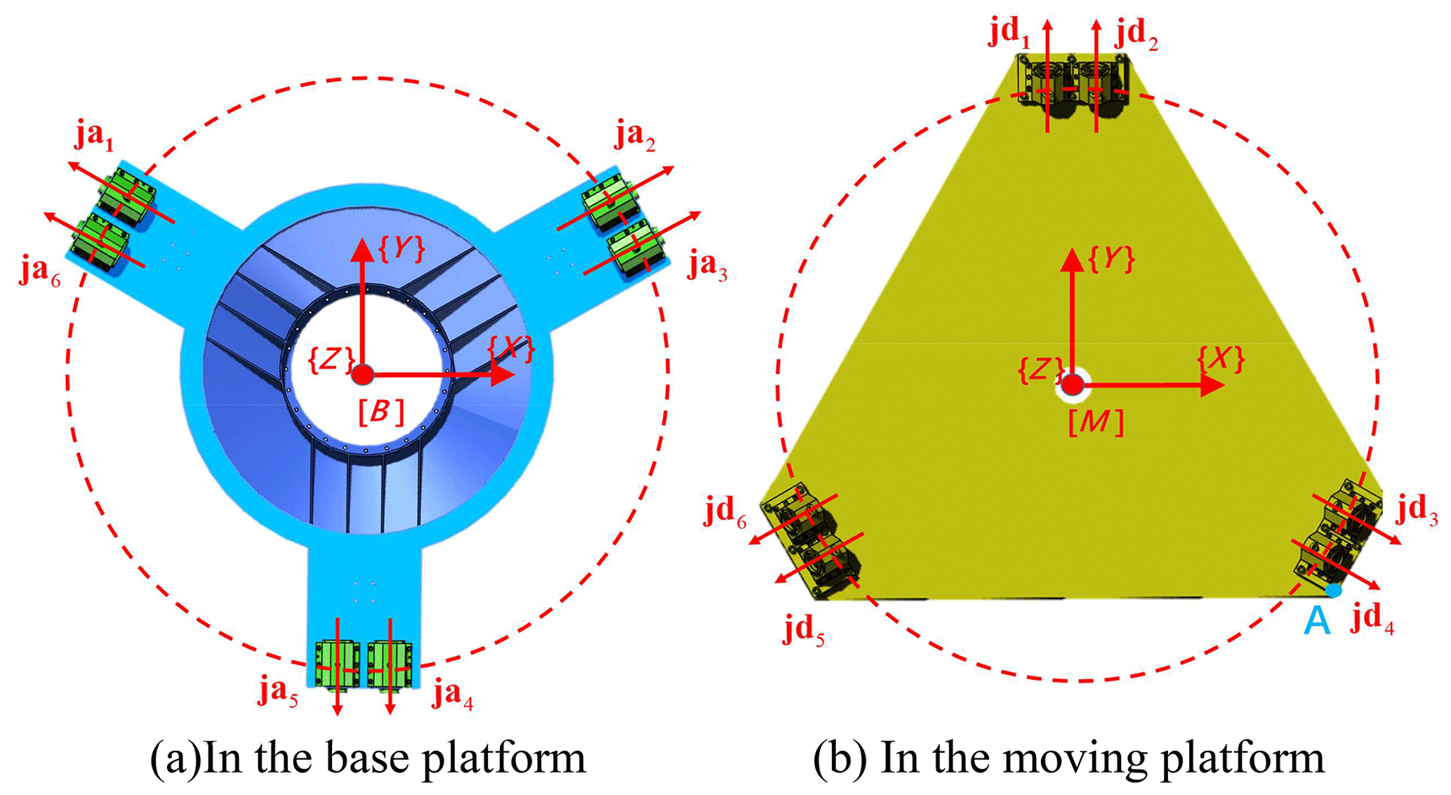
In the study of the kinematic and dynamic performance of the EDSP, two Cartesian coordinate systems need to be built on the EDSP. System {B} is fixed at the center of the base platform as the reference coordinate system. System {M} is located at the center of the moving platform and follows its movement. {A1}3×6 and {A2}3×6 are the center position matrices of the Hooke's joints connected to the moving and base platforms, respectively. The 3-DOF linear motions and 3-DOF rotational motions constitute the 6-DOF motion of the moving platform. The linear motions are denoted as surge (q1), sway (q2), and heave (q3), representing motion along the xB-, yB-, and zB axes, respectively. The rotational motions include roll (q4), pitch (q5), and yaw (q6), representing rotation around the xB-, yB-, and zB axes, respectively. In other words, expresses the 6-DOF motion of the EDSP.
2.2 Inverse kinematics
The inverse kinematics solution of the system indicates the mapping of each chain's length to the position and attitude of the moving platform. The position vector of the branch chain can be expressed as the vector from one Hooke's joint on the base platform to the corresponding one on the moving platform.
where L3×6 is the matrix of the position vector of six branch chains, and c3×6 is the combined matrix of linear motion on the moving platform.
The rotation matrix expresses the rotational motion of the moving platform with respect to the base; this matrix transfers the coordinate values of {A1}, from {M} to {B} in Eq. (1).
where C and S are short forms for cos and sin functions.
By computing the 2-norm of each column vector L in Eq. (1), the length of each driven branch chain can be obtained.
Inverse kinematics could be applied in control strategy, as indicated in Sect. 3.
2.3 Calculation of passive rotation and length error of driven branch chain
The driven branch chain and the axle of the connecting joint are shown in Fig. 2. Li is the direction vector of the ith driven branch chain, which is expressed by Eq. (1). Each Hooke's joint has 2 DOFs of rotation. The axes of rotation of the Hooke's joints (Fig. 2) are jai, jbi, jei, and jdi. For each Hooke's joint, another axis, indicating the direction of the connected driven branch chain in Fig. 2, can be defined to support our understanding of PR in the following, such as jci and jfi parallel to LEGi (Fig. 2). It should be noted that the Hooke's joint does not provide a rotational DOF on this axis. According to Gruebler's formula (Norton, 1999), to realize 6-DOF motion on a moving platform, each driven branch chain should have 6-DOF mobility. Thus, the driven branch chains applied in EDSP could have the structures of 2-1-3 (U-P-S) or 2-2-2 (U-C-U) DOF. When equipped with a Hooke's joint, the branch chain on EDSP has 2-2-2 DOF mobility. Except for the 2 degrees of rotational freedom offered by each Hooke's joint, each lead screw has 1 degree of rotational freedom and 1 degree of translational freedom, and these 2 DOFs have a linear interaction with each other. When the moving platform experiences a relative rotation of the base platform, the two Hooke's joints on one branch chain will have a related rotation around jci (jfi). However, these Hooke's joints do not provide rotational DOFs for jci and jfi. Thus, this type of PR can occur only on the lead screw, because the lead screw can provide extra rotational freedom on its axis Li. The PR will cause undesired linear motion on the lead screw, and it will not be considered by the control system. This accompanying linear motion has an effect on pose accuracy. To understand the error from the source of the PR and improve the pose accuracy, the PR angle must be calculated. The generated length shift must also be compensated for.
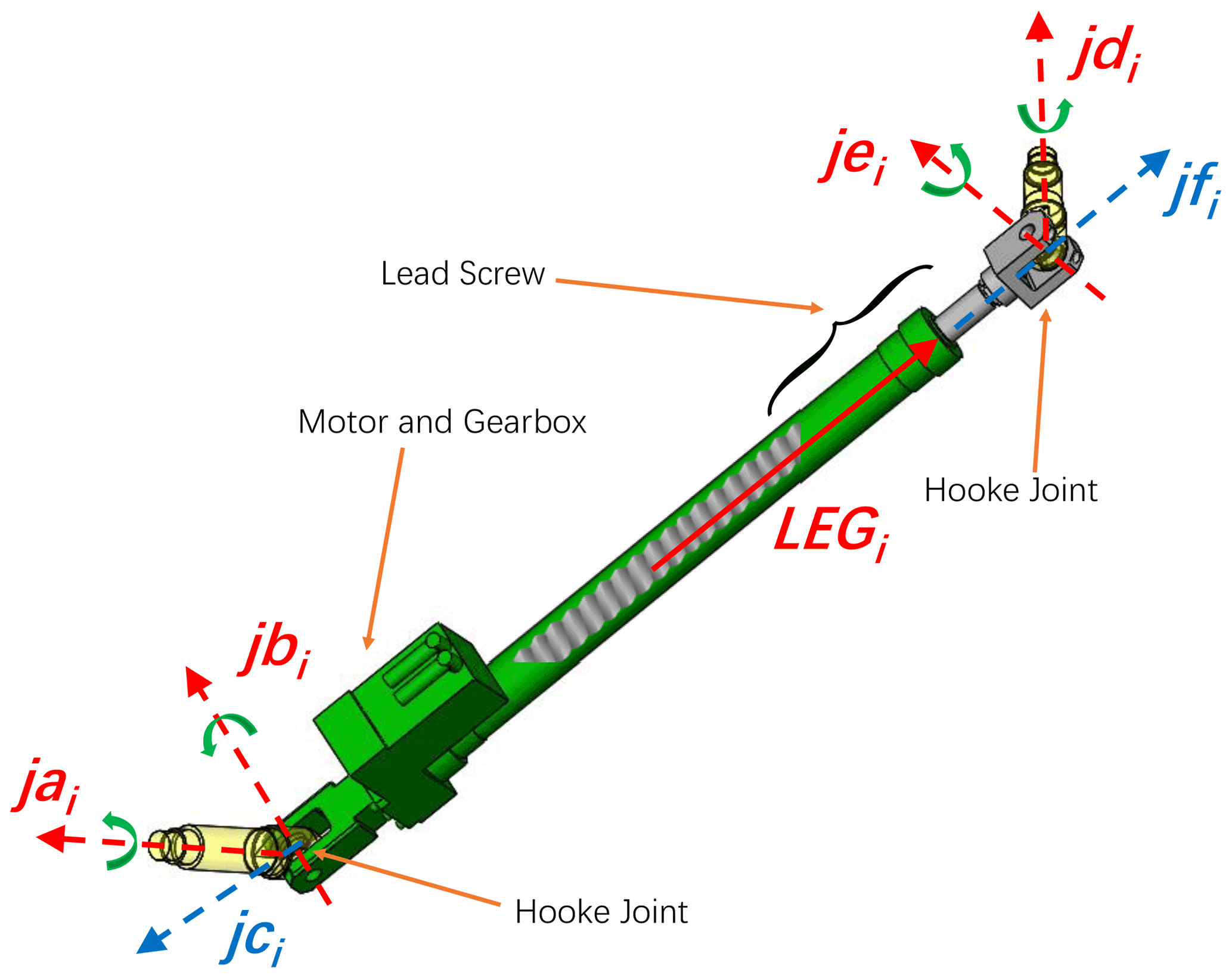
In the following equation, jai and jdi are the unit vectors on the axis of the Hooke's joint connecting the base and moving platforms, respectively (Figs. 2 and 3), as described in the reference coordinate system {B} (Fig. 3).
In the following equation, jbi and jei represent unit vectors of the axes of the universal joints on the side of the branch chain. The variation in angle between jbi and jei can be regarded as the angle of PR during operation. Based on the configuration of the EDSP and characteristics of the Hooke's joint, the aforementioned vectors will have interrelation as given below.
Based on Eq. (7), jbi and jei can be expressed by the vector cross product as follows.
The angle between jbi and jei is
Thus, the length error of the ith driven branch chain caused by PR is
where Ph is the lead of screw.
The length error of the actuators cannot be measured by the sensor located on the motors. Thus, the length error caused by PR cannot be compensated for by the control system, which is based on the motor feedback signal.
To minimize the effect of PR, the length error of the respective chains should be modeled and considered in the control strategy. As mentioned in Sect. 2, the length error can be calculated using the EDSP configuration, target position, and posture of the moving platform. Thus, it is possible to compensate for the error by considering the PR in the control loop to achieve a higher pose accuracy.
In the control strategy of the EDSP, marked within the blue dotted frame shown in Fig. 4, the target displacement of each branch chain, Δleni in Eq. (11), can be calculated by the inverse kinematic unit based on the input command of the target position and posture of the moving platform. The encoder on the motor records the feedback signal of the rotor position as a feedback signal in the control loop, which can be used to deduce the real-time length of the driven branch chain. The difference between the feedback length and the target length of the driven branch chain Δlen is provided as the input to the controller. Then, the controller outputs the control signals to drive each motor and branch chain. In most cases, PID (proportion integration differentiation) has been chosen because of its simple principle and reliable properties. Finally, the motor drives the lead screw to reach the target position and posture of the moving platform.
A brief and simple strategy to avoid the effect of PR is to reverse the length shift caused by PR to the commanded length as a component of the control input. Thus, the corrected length lenCi of the driven branch chain can be corrected for the error to reach an ideal value that can be used to achieve the target position and posture.
To eliminate the effect of PR, additional units need to be added to the general control loop to correct the command length of the driven branch chains. Based on the input of the structure's parameters and target position and posture, the PR angle and length error on each driven branch chain can be precisely calculated using Eqs. (1)–(8). The length error caused by PR should be considered for the control system. The target length pluses its length error to correct the length of each branch chain. Thus, the target length, compensating length, and feedback length of the driven branch chains consist of the input to the controller with the compensate function.

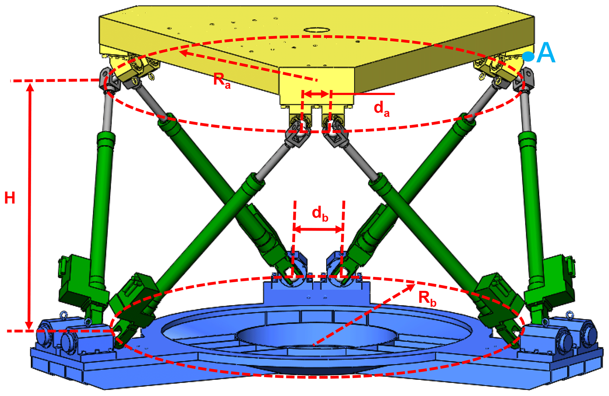
To demonstrate the effectiveness of PR compensation, a simulation model was built, which includes an inverse solution and length error. The EDSP chosen here is considered on a large scale, which shows a heavy payload capacity. The configuration parameters are as follows: Ra=1.2, Rb=1.5, da=0.2, db=0.3, and H=1.511 (units: m), as shown in Fig. 5.
4.1 Schematic design and evaluation index
Considering the 6-DOF movement abilities of the EDSP, both linear and rotational motions are included in the virtual test. Considering the lead screw motion range and the possibility of interference with other components, the movement range of the EDSP is limited to ±0.5 m (for linear motion) and ±30∘ (for rotational motion). In view of its 6-DOF movement ability and symmetrical structure, rotational motion around the y and z directions (Ry and Rz) and linear motion along the x and z directions (Lx and Lz) were selected for testing during simulation.
To verify the pose accuracy, an observation point was chosen to represent the moving platform's position and posture. It is well known that the point has the furthest distance to the center of {M} on the edge of a moving object will exhibit the highest error and fluctuation during motion. The furthest point that has a worst performance in motion accuracy because the distance would amplify the error. For example, if the moving platform has a posture error in angle α, point p in the moving platform has the position error . A longer distance dp would bring a larger position error Ep. Thus, the observation point was set at the edge of the moving platform (marked as point A in Figs. 1–5). For each test, the actual position of the observation point was compared to its ideal position. The distance between them is regarded as the pose error to evaluate the movement accuracy.
4.2 Simulation result and analysis
In this section, the simulation results are analyzed to demonstrate the influence of PR and the improvement in accuracy by using a compensation control strategy.
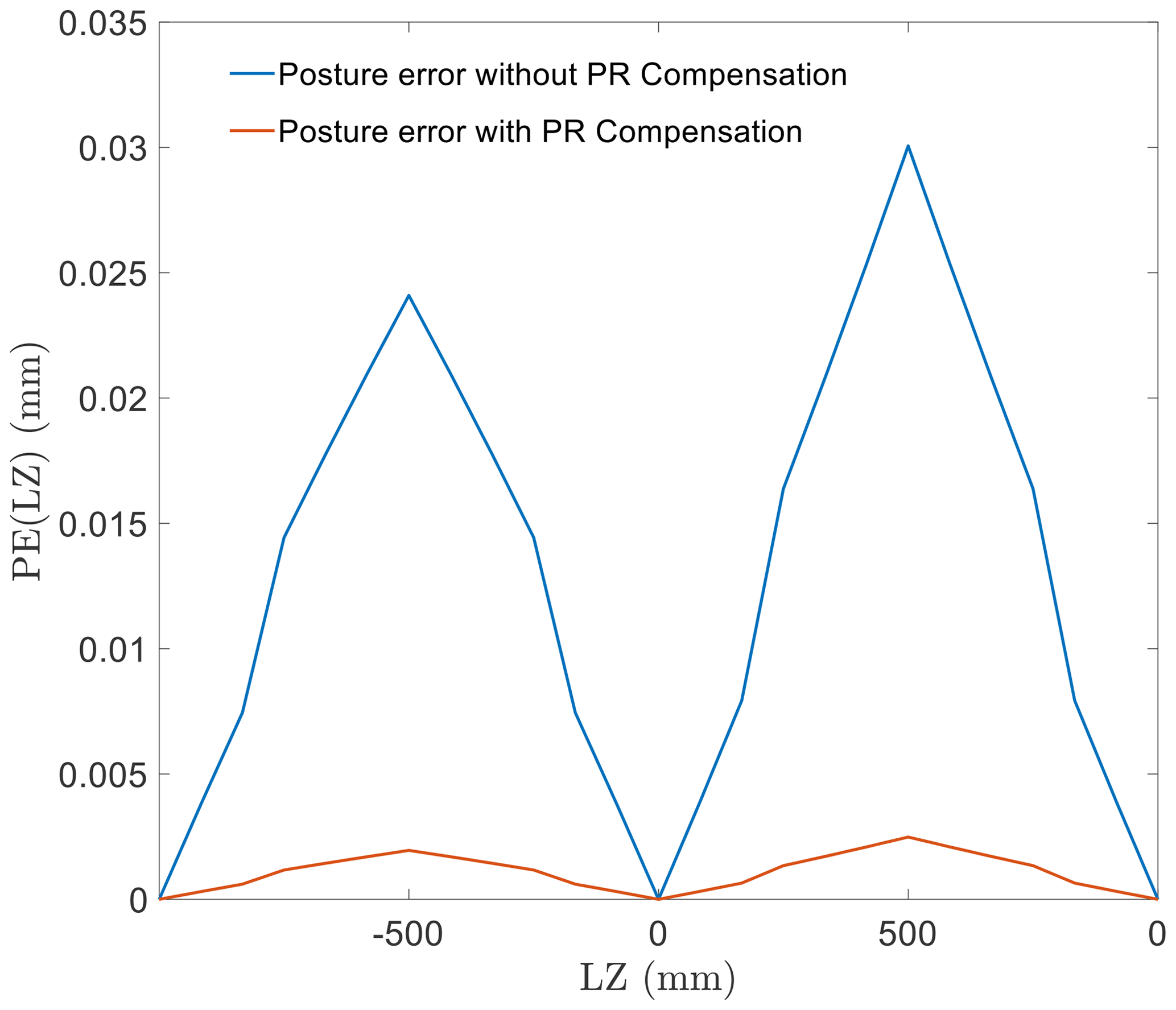
Figure 6 shows the pose error in linear motion along the z direction. First, as the displacement in the z direction advances further, the pose error caused by the PR gradually accumulates and grows. After compensating for the length shift, as it is changed by the PR, the motion accuracy shows a significant improvement.
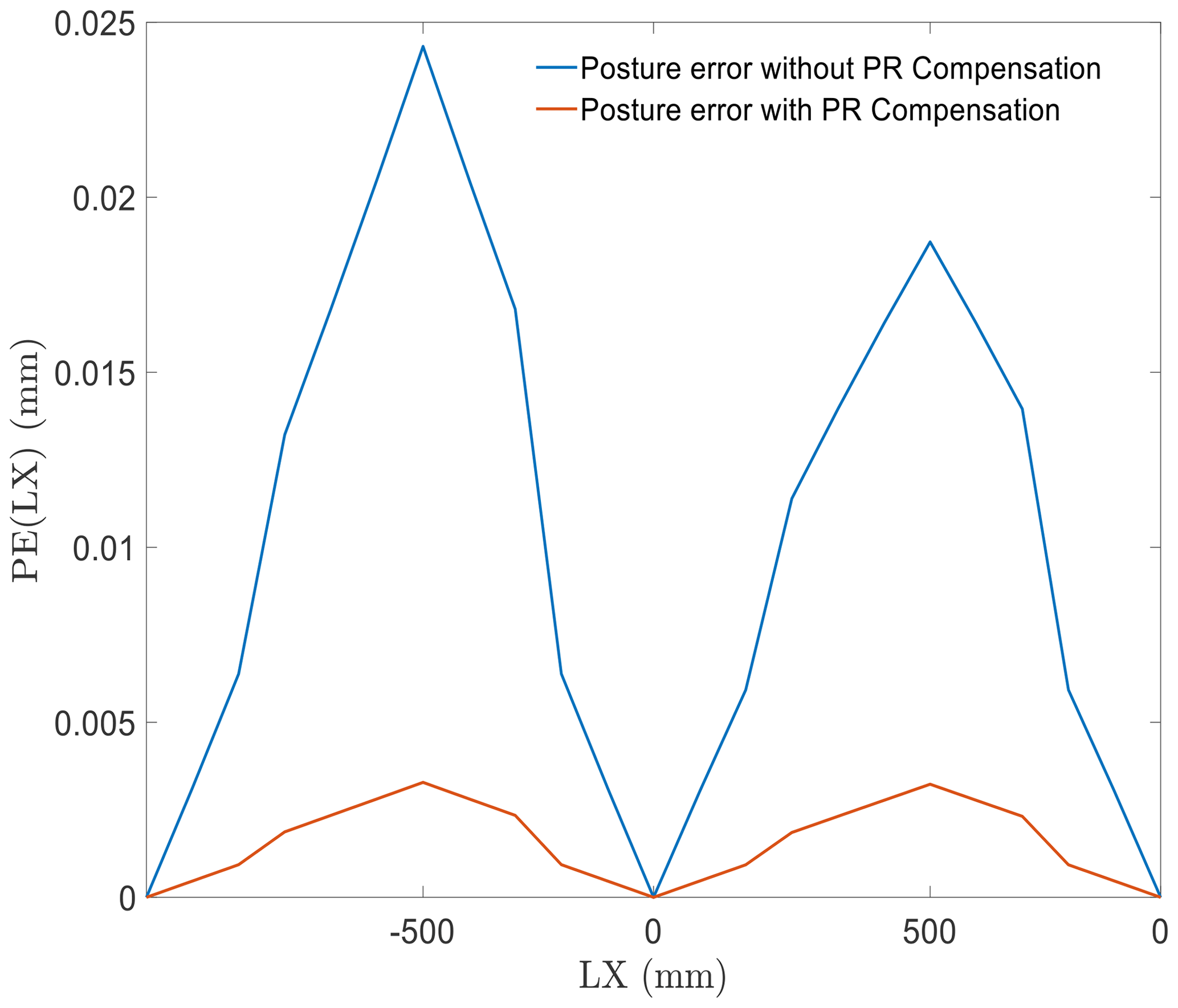
The error in linear translation along the x direction is shown in Fig. 7. This error in linear motion shows a trend very similar to that along the z direction, with error accumulation as well as with optimization effect from the compensation control scheme. The compensation function works well to improve the pose accuracy by reducing the PR-induced error.
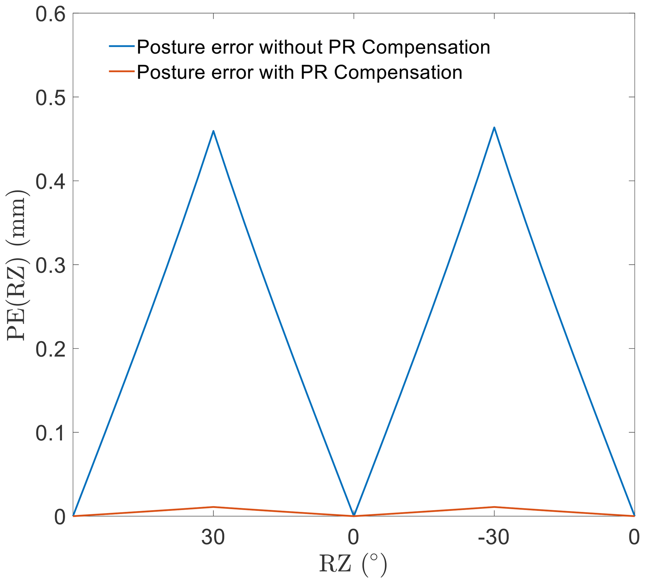
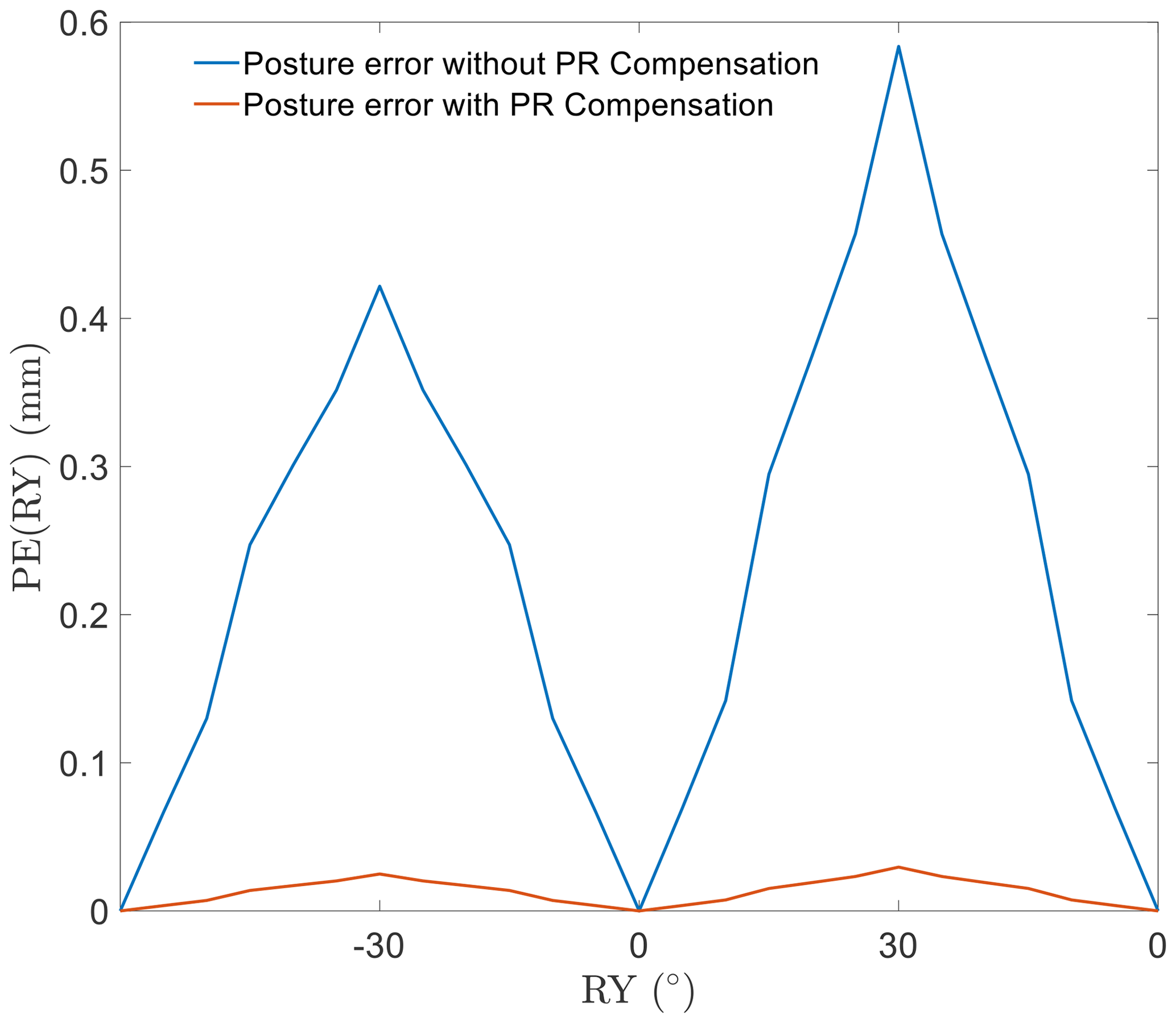
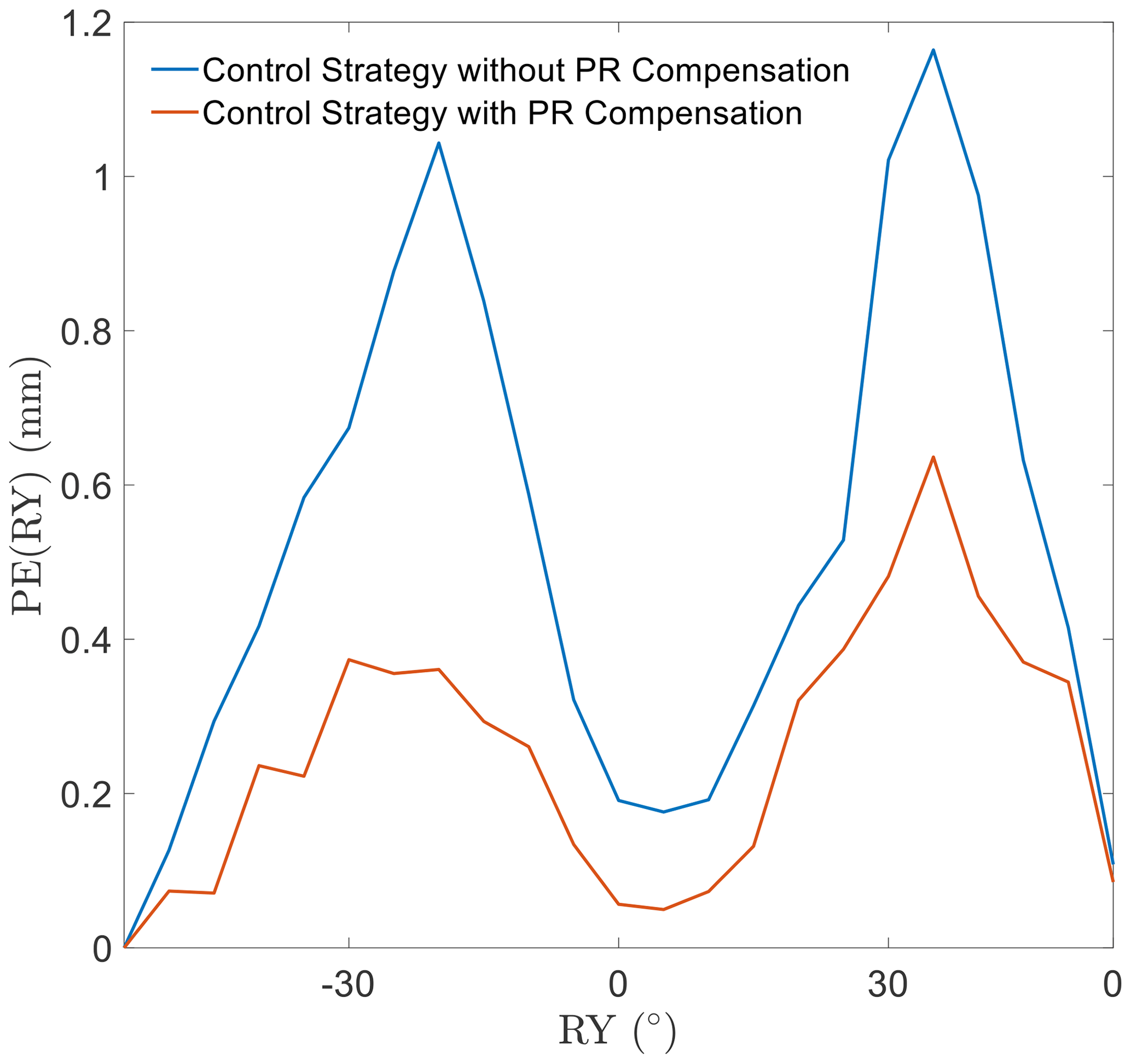
A similar situation for rotational motion is shown in Figs. 8 and 9. The regularity of the rotational error and the effectiveness of the optimization are consistent with those of the linear motion.
Considering the simulation results, excluding the abovementioned performance, PR shows different effects along different directions. It is important to realize that the motion in different directions causes PR on different scales. Further movement would result in a more severe inaccuracy, affected by PR. The movement accuracy of the EDSP shows a significant improvement after compensating for the length error of the driven branch chain caused by PR.
In this section, the motion performances of the two aforementioned control strategies are evaluated experimentally. The results are analyzed and compared with the simulation results.
5.1 Design of the experiment
The EDSP chosen for the experiment had the same configuration parameters as the simulation model. Almost all the components were made of stainless steel. The encoders attached to the motor side are regarded as the feedback elements of the control system. The large size parameters and the stainless-steel structure imply a heavy, moving platform load, which will have a significant effect on the control effect and movement performance, such as a relatively observable overshoot.
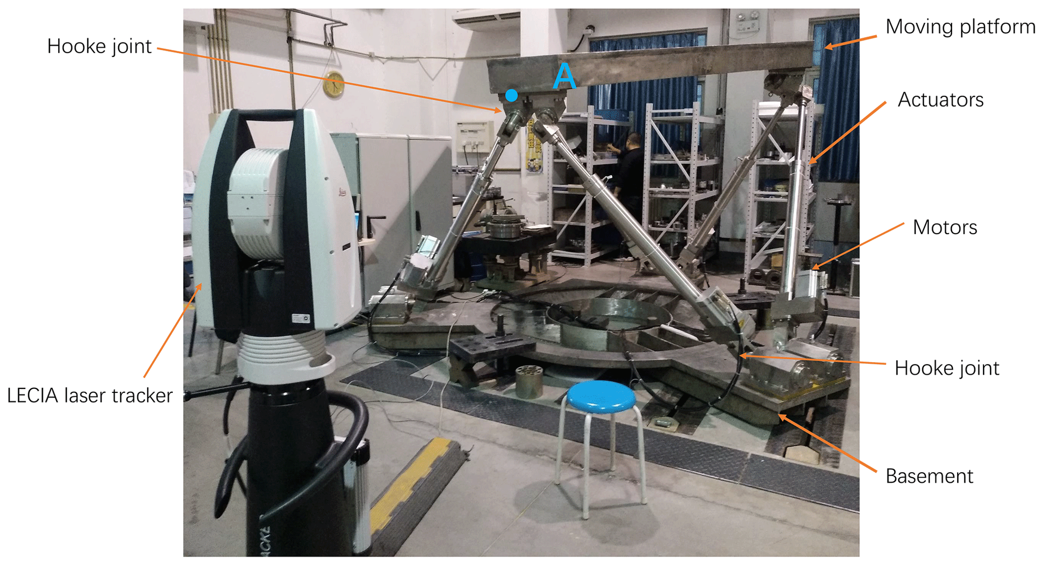
The experiment was designed using the same process as in the case of the simulation mentioned in Sect. 4. First, an observation point is set at the edge of the moving platform, similar to the observation point in the simulation. The position of the observation point was recorded by the LECIA laser tracker AT960 during each motion. However, in position measurement, the laser tracker has a higher measuring accuracy when the target gets closer to the lens (Conte et al., 2014). Thus, in our work, we set the observation point near to the LECIA laser tracker AT960. The experimental setup of the electrically driven Stewart platform and laser tracker is shown in Fig. 10. All the position data were recorded in the SpatialAnalyzer software and then processed using the same program as the one used in the simulation. Finally, the experimental results of the two control strategies are presented and compared.
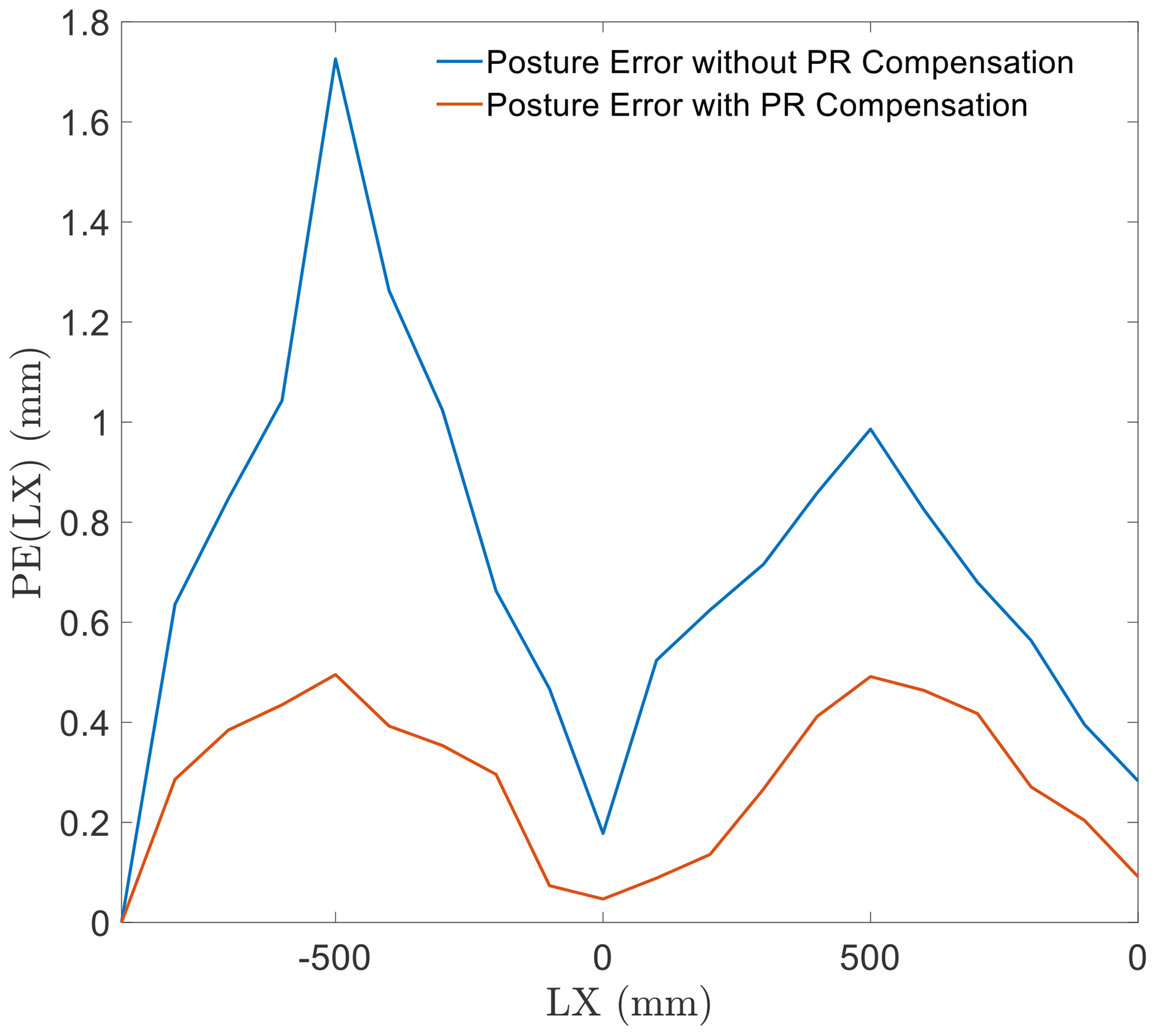
Table 1Comparison of maximum error in simulation and experiment (unit: mm).

5.2 Experiment results and discussion
The experimental results are presented in Figs. 11–14. In this section, all the results are analyzed and compared with the simulation results.
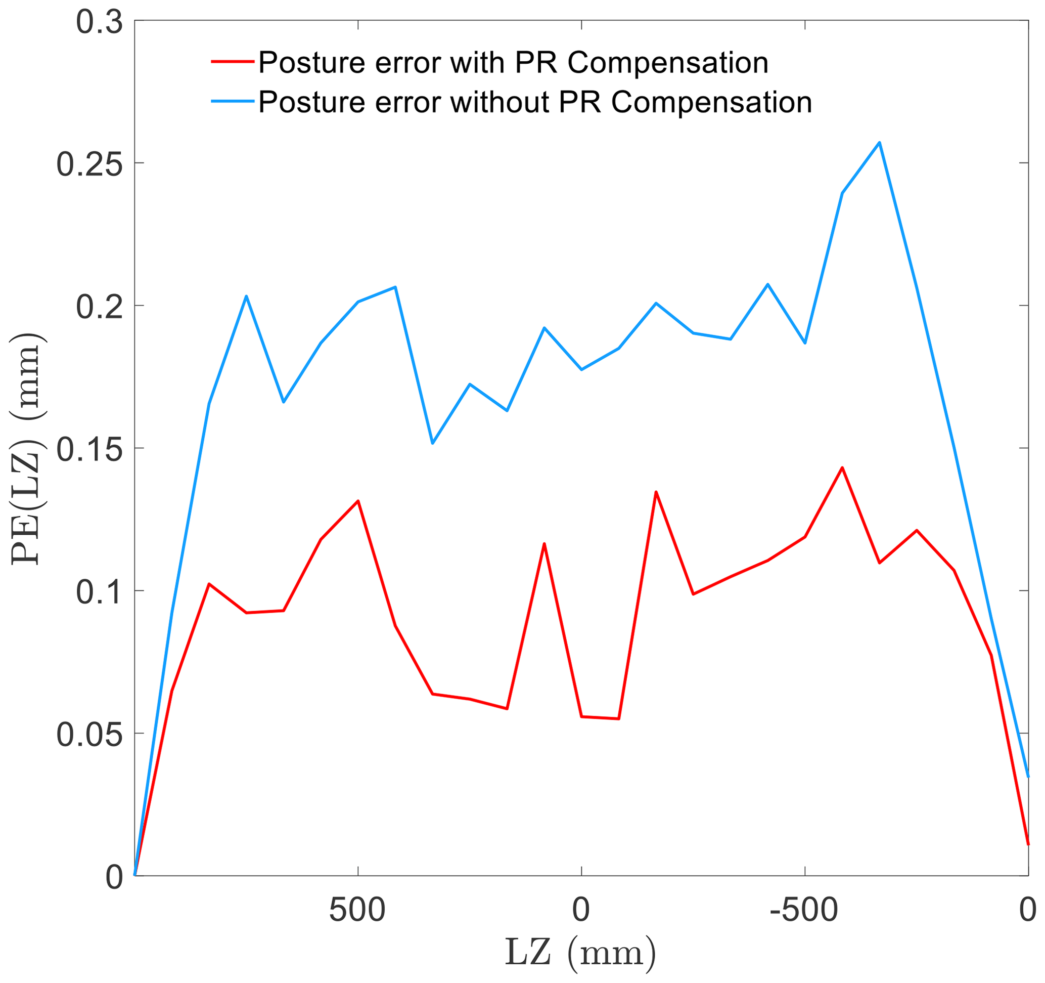
The pose error in linear motion in the z direction is shown in Fig. 11. Based on the result, the compensation function in the control system was proven to provide a significant improvement in the pose accuracy. Compared to other motions in the experiment, the linear motion in the z direction exhibits a relatively smaller pose error. However, its performance does not exhibit regularity, unlike in the case of simulation.
Regarding the linear motion in the x direction, the experiment yielded a curve similar to that obtained in the simulation. In addition, as in the simulation, the error increases with an increase in distance from the starting point. In addition, the pose accuracy improves significantly after compensating for the effect of PR.
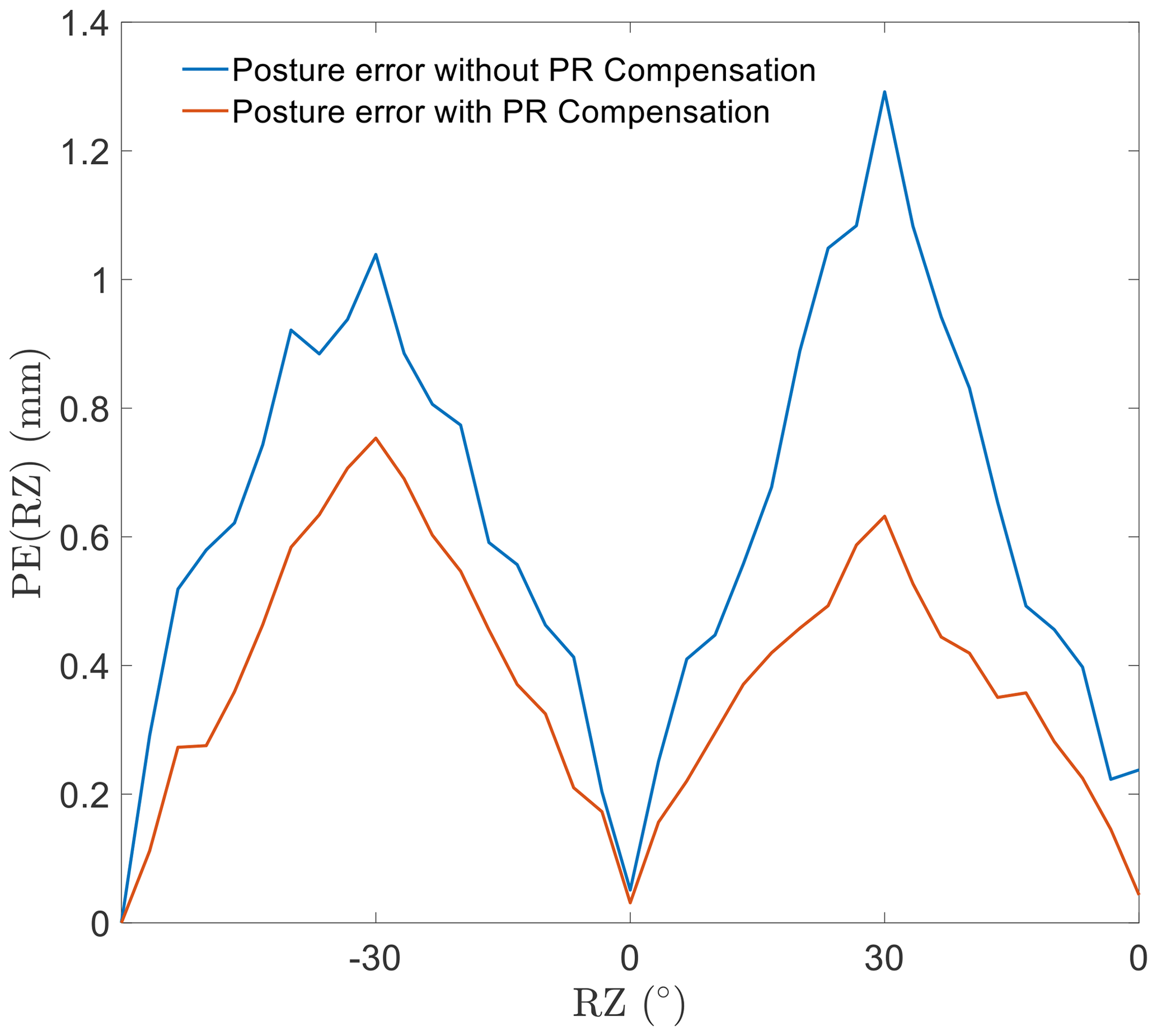
In the case of rotational motion, the performance observed in the experiments matches with that in the simulation. In the rotational motion around the z and y axes, the compensation control strategy improves the pose accuracy.
In conclusion, the experimental results demonstrate that the effect of PR is the same as that deduced by calculation. The pose error in the experiments, caused by PR, matches the movement performance obtained in the simulations. The PR compensation control works well in the pose accuracy improvement of the EDSP. In addition, the EDSP showed better pose accuracy in linear motion along the z direction.
A control method to compensate for posture errors caused by PR for one type of 6-DOF EDSP is presented. The calculation of the PR angle was based on the inverse kinematics and configuration parameters. A general PR compensation control strategy was designed to avoid the effects on pose accuracy. The calculation and control strategies were verified in the simulation, where linear and rotational motions were designed for the comparison of control strategies. The results of the simulation were compared for different motions and their performance before and after compensation. Finally, experiments were designed based on the simulation conditions to test the effectiveness of the compensation. Based on the discussion on the results of the simulation and experiment, the PR shows a certain regularity in some types of motion, whereas the compensation function demonstrates effectiveness in reducing the influence of PR on the movement performance of the 6-DOF EDSP.
In the next step, a more precise dynamic model could be set up to realize a closer simulation with the physical test platform. At the same time, the friction and inertia of the structure would be included in simulation.
The raw model (code) required to reproduce these findings cannot be shared at this time as the data also form part of an ongoing study.
All the data used to support the findings of this study are included within in the relevant figures and tables in the article.
PW developed the model code and performed the simulations. QH and PW designed the experiments, and all authors carried them out together. PW prepared the article with contributions from all co-authors.
The contact author has declared that neither they nor their co-authors have any competing interests.
Publisher's note: Copernicus Publications remains neutral with regard to jurisdictional claims in published maps and institutional affiliations.
This work was supported by the National Natural Science Foundation of China (grant no. 51105094), National Key R&D Program of China (grant no. 2020YFB2009701), and the Science Foundation for Post Doctorate Research of Heilongjiang Province.
This paper was edited by Daniel Condurache and reviewed by three anonymous referees.
Ahmad, A., Andersson, K., Sellgren, U., and Boegli, M.: Evaluation of Friction Models for Haptic Devices, DSCC 2013 ASME Dynamic Systems and Control Conference, 21–23 October 2013, Stanford university, Munger Centre, Palo Alto, CA, USA, 2013.
Chen, X. S., Chen, Z. L., Kong, M. X., and Xie, T.: An accurate solution for forward kinematics of 6-SPS Stewart platform based on neural network, Journal of Harbin Institute of Technology, 2002, 120–124, 2002
Conte, J., Santolaria, J., Majarena, A. C., Brau, A., and Aguilar Martín, J. J.: Laser Tracker Error Modeling and Kinematic Calibration Strategy, Key Eng. Mat., 615, 63–69, https://doi.org/10.4028/www.scientific.net/kem.615.63, 2014.
Ding, B., Cazzolato, B. S., Grainger, S., Stanley, R. M., and Costi, J. J.: Active Preload Control of a Redundantly Actuated Stewart Platform for Backlash Prevention, in: IEEE International Conference on Robotics & Automation, Karlsruhe, Germany, 6–10 May 2013, 1908–1915, https://doi.org/10.1109/ICRA.2013.6630830, 2013.
Du, S., Schlattmann, J., Schulz, S., and Seibel, A.: Passive Rotation Compensation in Parallel Kinematics Using Quaternions, P. Appl. Math. Mech., 16.1, 51–52, https://doi.org/10.1002/pamm.201610014, 2016.
Du, S., Schlattmann, J., Schulz, S., and Seibel, A.: Passive Rotation of Rotational Joints and Its Computation Method, Springer, Cham, Vol. 73, https://doi.org/10.1007/978-3-030-20131-9_36, 2019a.
Du, S., Schlattmann, J., Schulz, S., and Seibel, A.: On the origin of passive rotation in rotational 40 joints, and how to calculate it, P. Appl. Math. Mech., 19, e201900298, https://doi.org/10.1002/pamm.201900298, 2019b.
Garagi, D. and Srinivasan, K.: Adaptive Friction Compensation for Stewart Platform Machine Tool Structures, IFAC Proceedings Volumes, 35, 555–562, 2002.
Hernandez, E., Valdez, S. I., and Sanchez, E.: On the Numerical Modelling and Error Compensation for General Gough-Stewart Platform, Int. J. Adv. Robotic Syst., 11, 1680–1681, 2014.
Huang, Q., Jiang, H., Zhang, S., and Han, J.: Spacecraft docking simulation using hardware-in-the-loop simulator with stewart platform, Chin. J. Mech. Eng., 18, 415–418, https://doi.org/10.3901/CJME.2005.03.415, 2005.
Jáuregui-Correa, J. C., López-Cajún, C. S., García-Arredondo, A., Hernández-Martínez, E. E., and Ceccarelli, M.: Validation Process of Pose Accuracy Estimation in Parallel Robots, J. Dyn. Syst.-T. ASME, 137, 064503, https://doi.org/10.1115/1.4029346, 2015.
Kim, Y. J., Seo, J. H., Kim, H. R., and Kim, K. G.: Impedance and admittance control for respiratory-motion compensation during robotic needle insertion – a preliminary test, Int. J. Med. Robot. Comp., 13, https://doi.org/10.1002/rcs.1795, 2017.
Li, Y., Yang, X. L., Wu, H. T., and Chen, B.: Optimal design of a six-axis vibration isolator via Stewart platform by using homogeneous Jacobian matrix formulation based on dual quaternions, J. Mech. Sci. Technol., 32, 11–19, https://doi.org/10.1007/s12206-017-1202-1, 2018.
Liu, Y.: Applying Indoor GPS System to Measure the Attitude and Position of the Stewart Platform, MS thesis, National Chiao Tung University, China, 2016.
Norton, R. L.: Design of Machinery, 2nd Edn., WCB McGraw-Hill, Boston, 1999.
Porath, M., Bortoni, L., Simoni, R., and Eger, J. S.: Offline and online strategies to improve pose accuracy of a Stewart Platform using indoor-GPS, Precis. Eng., 63, 83–93, https://doi.org/10.1108/IR-12-2018-0248, 2020.
Wu, D., Gu, H., and Li, P.: Adaptive Fuzzy Control of Stewart Platform under Actuator Saturation, World Academy of Science, Engineering & Technology, 36, 680–685, 2009.
Wu, X., Zhou, F., and Wang, Y.: Design of high precision Stewart platform motion control system, Transducer and Microsystem Technologies, https://doi.org/10.13873/J.1000-9787(2019)09-0070-04, 2019.
Zhang, D., Zhang, G., and Li, L.: Calibration of a six-axis parallel manipulator based on BP neural network, Ind. Robot, 46, 692–698, https://doi.org/10.1108/IR-12-2018-0248, 2019.
- Abstract
- Introduction
- Modeling and analysis of passive rotation
- Compensation for the effect of PR
- System simulation
- Experiments and measurement equipment
- Conclusion
- Future work
- Code availability
- Data availability
- Author contributions
- Competing interests
- Disclaimer
- Financial support
- Review statement
- References