the Creative Commons Attribution 4.0 License.
the Creative Commons Attribution 4.0 License.
 | 19 Nov 2020
Mechanism analysis of ancient Chinese crossbows
Jie Dong
Yang Zhang
Tenigeer
Yan'An Yao
In ancient China, people integrated the original bow, the bowstring, and a cam mechanism to develop a powerful weapon which was named the crossbow. It was one of the most frequently used weapons during the 5th century BC to the 18th century AD. Because it used the elasticity of the bow and the bowstring to shoot arrows, it was used for long-distance attacks. After the 4th century BC, the technology of producing crossbows was very sophisticated. Since the topological structure of the crossbow has a different configuration during the shooting process, it is defined as a reconfigurable mechanism. This paper uses the topological matrix to present the topological structures of the original crossbow and the Chu State repeating crossbow. A brief history of the development of the crossbow in ancient China is given. The Mongolian traditional bow is provided as an example to describe the manufacturing process of the bow. Then, topological structures of the original crossbow and Chu State repeating crossbow are derived. The degrees of freedom of two crossbows are proposed to check the constrained motion. Finally, 3D computer graphics of two crossbows are presented to illustrate the shooting processes.
- Article
(4240 KB) - Full-text XML
- BibTeX
- EndNote


The original crossbow evolved from the traditional bow. In ruins, stone arrowheads have been unearthed, dating from 1.7 million years ago to 10 000 years ago. In addition, in ruins dating back to the Neolithic Age, many arrowheads have been excavated which are made from stones or animal bones. Therefore, it is widely believed that prehistoric people's behavior progressed from throwing stones to using bows and arrows in hunting. People's interest in hunting implements continued to develop over the next few thousand years, and this influenced the development of human projectile weapons (Lu, 2003).
In ancient times, an original crossbow was called a “nu”. This could be described as a developed weapon which used the delayed force of the bow's bowstring to shoot arrows. It was developed by adding the frame and a trigger mechanism onto a traditional bow. When the trigger mechanism tightened the bowstring, it facilitated the aiming and shooting of arrows. This development improved the bowstring which previously had to be pulled by human force, thus remedying the two issues of people being unable to aim for long periods of time and being inaccurate in shooting (Zhang et al., 2004; Hsiao and Yan, 2014). The crossbow is fundamentally an implement of warfare of Eurasia, and more Asian than European. It had little spread in South Asia until the 8th century AD. Around the 16th century AD, it spread to Africa and the Americas. The characteristics of Chinese crossbows are that the parts are easy to re-assemble and are exchangeable. Western crossbows are often complex, and several moving parts must have been fabricated.
In the Spring–Autumn Period (770–476 BC), the original crossbow had been widely used. There are a lot of ancient documents which recorded information about the original crossbow. In the Warring States Period (475–221 BC), it played an important part in wars. The oldest surviving text which records the original crossbow is The Art of War dated from 498 BC (Needham, 1954). The earliest unearthed trigger mechanism was found in Qufu in Shandong Province, and it can be dated back to the 6th century BC (Zhong, 2008). In view of the structures, the development of the original crossbow can be divided into two stages (Lu et al., 2000). Before the Han Dynasty (206 BC–AD 220), the trigger mechanism has no bronze casing and is fixed in the wooden frame directly. After the Han Dynasty, there are two modified designs in the original crossbow. One is to increase the bronze casing and the other is to carve a scale table with a shooting range onto the trigger mechanism. The parts of the trigger mechanism installed in the bronze casing can provide higher tension than installed in the wooden frame. In consequence, the shooting range has increased greatly. Adding a scale table to the trigger mechanism helps the archer to shoot the target more accurately. With the continuous improvement of the crossbow in later generations, the structure and shape of the crossbow had become complicated. According to the size of the crossbow, it can be divided into two categories: large mechanical crossbow and small handheld crossbow. The large mechanical crossbow usually combined several crossbows and used mechanical devices to enhance the power and stability of the crossbow (Liu, 1962). Compared with the large mechanical crossbow, the small handheld crossbow was less powerful but more flexible. Until the Qing Dynasty (1644–1911 AD), the crossbow was still used and was the essential implement of warfare. The core technology of a crossbow is the trigger mechanism that is made of bronze. Its function is to stretch the bowstring and keep the elastic energy within the bow and the bowstring. More than 2000 years later, the structure of the crossbow is similar, making it one of the longest-lived arms in ancient China.
In addition, there was a type of crossbow that had the capability of shooting repeatedly, which is called a repeating crossbow. This was a further development of the crossbow. According to archeological findings, the earliest repeating crossbow was excavated in Jiangling, Hubei, China. It can be dated back to the 4th century BC (Jingzhou Museum, 2014). As it was unearthed in the territory of the Chu State in the Warring States Period, it was named the Chu State repeating crossbow. Its magazine was attached to the frame, which could hold 20 arrows and shoot 2 arrows per shot. However, the historical archives have never recorded such an ingenious invention. Since the crossbows are reconfigurable mechanisms, the topological structures change during operation and are not easy to describe in each shooting process. Therefore, the aim of this paper is to analyze the structures of ancient Chinese crossbows. The manufacturing process of the traditional bow is presented. Then, a brief history of the crossbow is given. The topological structures of the original crossbow and the Chu State repeating crossbow are represented by displaying a topological matrix. Finally, the shooting processes of the original crossbow and the Chu State repeating crossbow are illustrated.
Using elastic force to be able to shoot long distances was an important technology in ancient times. Therefore, the traditional bow was designed and appeared. When classifying bows according to the materials and manufacturing methods, they can be classified into three types. First, when a bow is made from one single piece of wood, it is named a “self-bow”. Second, when a bow is made from several layers or pieces of the same or a similar material, it can be called a “reinforced” or “compound” bow. Third, when a number of pieces or different materials are applied and combined to generate the body of a bow, it can be named a “composite” bow. Furthermore, when considering the shapes of bows, they can be divided into three types: “regular”, “semi-reflex”, and “reflex” bows (Needham, 1954). From the available data, the Chinese bow was a composite reflex bow and can be traced back to the 10th century BC.
The Mongolian people are well-known for their fine horse riding and good shooting skills. A Mongolian traditional bow is an important part of many Mongolian people's lives. According to the authors' research, production of the Mongolian traditional bow usually has four steps: material selection, material extraction, processing, and combination into a bow. The material selection of the bow is extremely important because it forms the basis for making a good bow. The raw materials include horns, beef tendons, bamboo, elm wood, birch wood, and other materials which have good elasticity. These raw materials are processed by craftsmen to make important parts of the bow and are then bonded and packaged with animal glue. It takes time and effort to make a bow and generally involves more than 100 procedures. The major procedures include the inner material of the bow, which is the bamboo that has been air-dried for more than 1 year, as shown in Fig. 1a. The most suitable tendon is derived from the buffalo's back. After air-drying, wetting, smashing, and drawing, the beef tendons become filaments; each one is about 5 cm long. The most favorable horns come from the buffalo and each horn slice is about 5 cm long. The inside of the bow (facing the shooter) is attached with horn slices, and the outside is stuck with beef tendons. The bow is tied with tendons, and the tendons are used for strapping and should also be glued together. Each end side of the bow is made of elm wood, which needs to be processed into a suitable shape with special tools and then bonded with the bamboo to complete the main part of the bow. Then, the birch bark needs to be covered to prevent moisture from settling on it. The outer layer of the bow is wrapped in snakeskin. This is for decorative purposes. Figure 1b shows a type of Mongolian traditional bow and arrow.
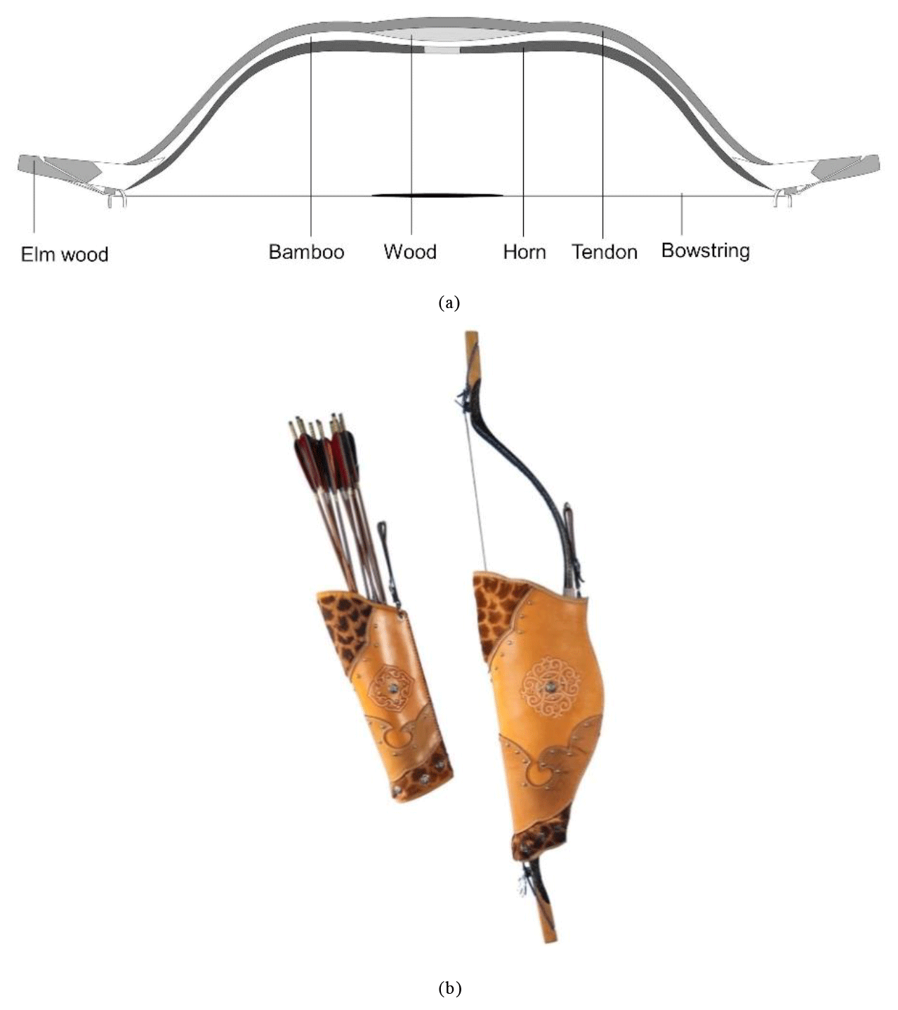
Figure 1Mongolian traditional bow (provided by Nuo Min, Wang).
3.1 Structural analysis
The topological structure of a mechanical device is distinguished by its types and numbers of links and joints and the incidences between them (Yan, 1998). A mechanical device that meets some changes in its topological structure during operation is called a reconfigurable mechanism (Yan and Kuo, 2006; Shi et al., 2017, 2020). Since crossbows have different topological structures in the shooting process, they are reconfigurable mechanisms. The topology matrix is a useful tool to represent the topological structures of reconfigurable mechanisms. It can be used to describe the variation process of crossbows. If the number of links of a crossbow is N, it is an N×N matrix. The diagonal element nii represents the type of the mechanical member i. The upper off-diagonal element nij represents the type of the joint incident to members i and j. The lower off-diagonal element nji denotes the sequence number of the connection between the members. If the number is 1, it means these two corresponding members are connected at the earliest possible time when the crossbow is being operated. If two numbers are the same, it means they are connected at the same time. If members i and j are not adjacent, .
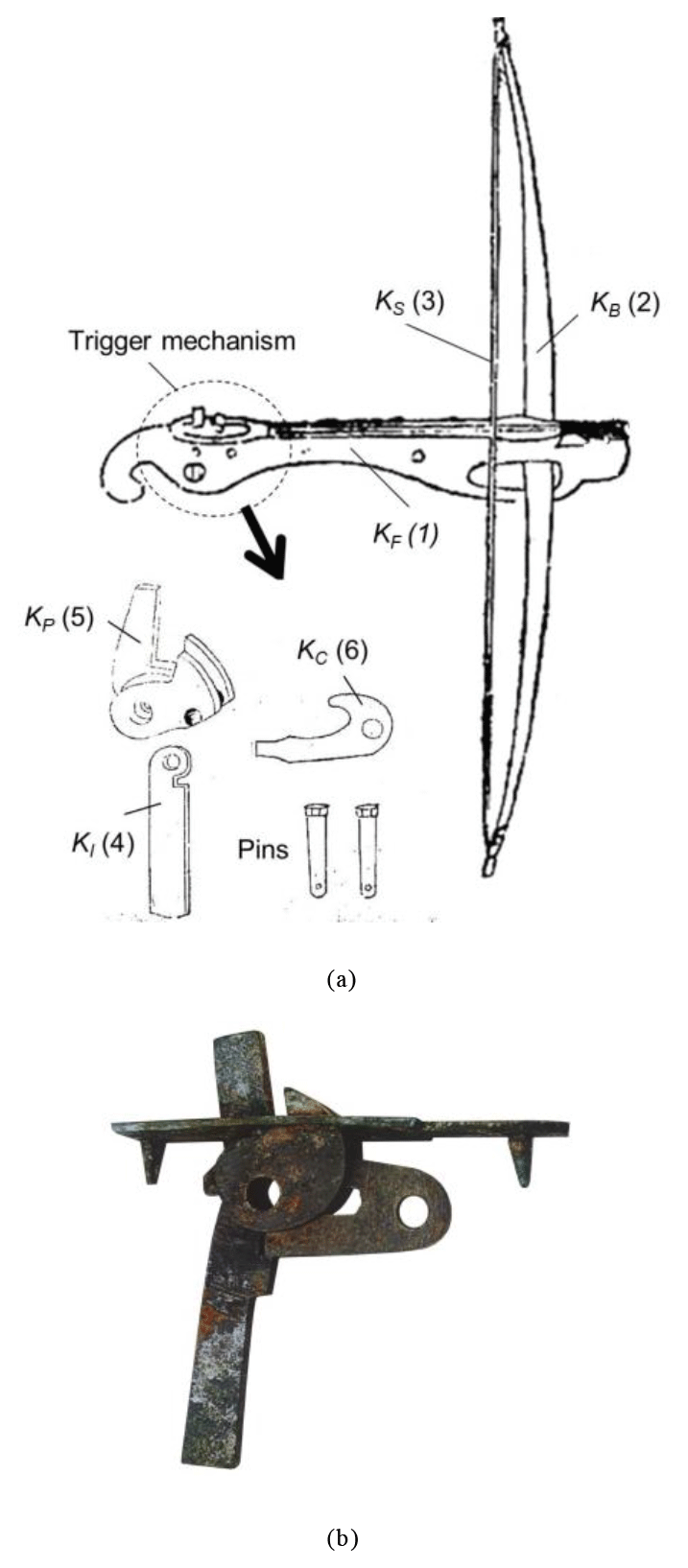
The original crossbow is a long-distance weapon that uses projectile force to shoot arrows. It consists of a frame, a bow, a bowstring, and a trigger mechanism, as shown in Fig. 2a (Mao, 2001). The frame is made of hard wood with holes drilled in it. The trigger mechanism, bow, and arrows are mounted on the opening and groove. The bow is a composite one, assembled with a few pieces of different woods, horns, bones, and sinew. Paint is applied to protect the wood from rotting. In addition, there are also some magnificent bronze and jade ornaments. Its strength is much greater than traditional handheld bows. The bowstring is made up of a few animal sinews, silk ropes, and guts. In order to enhance the elasticity, two or four single bowstrings can be twisted and combined into a strong bowstring.
The trigger mechanism installed on the frame is a kind of cam mechanism, which is the core part of a crossbow. Figure 2b shows a trigger mechanism that has been traced back to the 2nd century BC (Xu, 2007). It functions to hold the bowstring tight, consisting of an input link, a percussion link, a connecting link, and two pins. Most of the parts are made with bronze, and the sizes of the parts are accurate. Therefore, the original crossbow is a reconfigurable mechanism with six members, including the frame (member 1, KF), a bow (member 2, KB), a bowstring (member 3, KS), an input link (member 4, KI), a percussion link (member 5, KP), and a connecting link (member 6, KC) (Hsiao, 2013). The bow is connected to the frame and the bowstring is tied to the bow directly. The bow has elasticity and returns to the previous position after shooting. The joint incident to the bow and the frame can be considered a bow joint and denoted as JB. The kinematic characteristic of a bow joint is the same as a revolute joint. The relative motion between two incident members is the rotation about an axis. The degree of freedom of a bow joint is 1. The joint incident to the bowstring and the bow can be considered a bowstring joint and denoted as JBS. The feature of a bowstring joint is similar to a revolute joint. The degree of freedom of a bowstring joint can be considered to be 1.
3.2 Shooting process
To shoot an arrow, five steps must be undertaken: adjusting the trigger mechanism, stretching the bowstring, putting the arrow on the crossbow, releasing the bowstring, and shooting the arrow. The degree of freedom of the original crossbow is proposed to check whether the motion is constrained in the shooting process. Each step is described as follows.
3.2.1 Adjusting the trigger mechanism
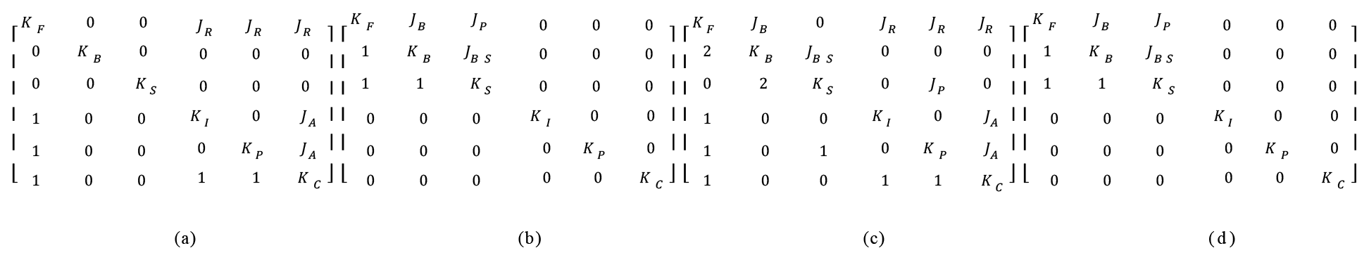
The first step of the shooting process is to adjust the trigger mechanism. The bow and the bowstring are temporarily immovable, as shown in Fig. 3a. Then, the input link, the percussion link, and the connecting link are adjusted so that the bowstring can be properly stretched, as shown in Fig. 3b. In this step, the input link is adjacent to the frame and the connecting link with a revolute joint JR and a cam joint JA, respectively. The percussion link is adjacent to the frame and the connecting link with a revolute joint JR and a cam joint JA, respectively. The connecting link is adjacent to the frame with a revolute joint JR. The corresponding topology matrix is shown in Fig. 4a.
The operation of this step consists of four members, three revolute joints, and two cam joints. Therefore, NL=4, CpR=2, NJR=3, CpA=1, and NJA=2. Based on Grubler–Kutzbach criteria (Yan, 1998), the number of degrees of freedom, Fp, of this step is
Therefore, the motion of this step is constrained.
3.2.2 Stretching the bowstring
Since the trigger mechanism has been adjusted to prepare for shooting, the parts of the trigger mechanism can be treated as being incorporated into the frame. The bowstring is stretched by the shooter, as shown in Fig. 3c. The bowstring is pulled by hand and is adjacent to the frame with a prismatic joint JP. The bow is adjacent to the frame and the bowstring with a bow joint JB and a bowstring joint JBS, respectively. The corresponding topology matrix is shown in Fig. 4b. When the bowstring has had sufficient stretching, as shown in Fig. 3d, the next step can begin.
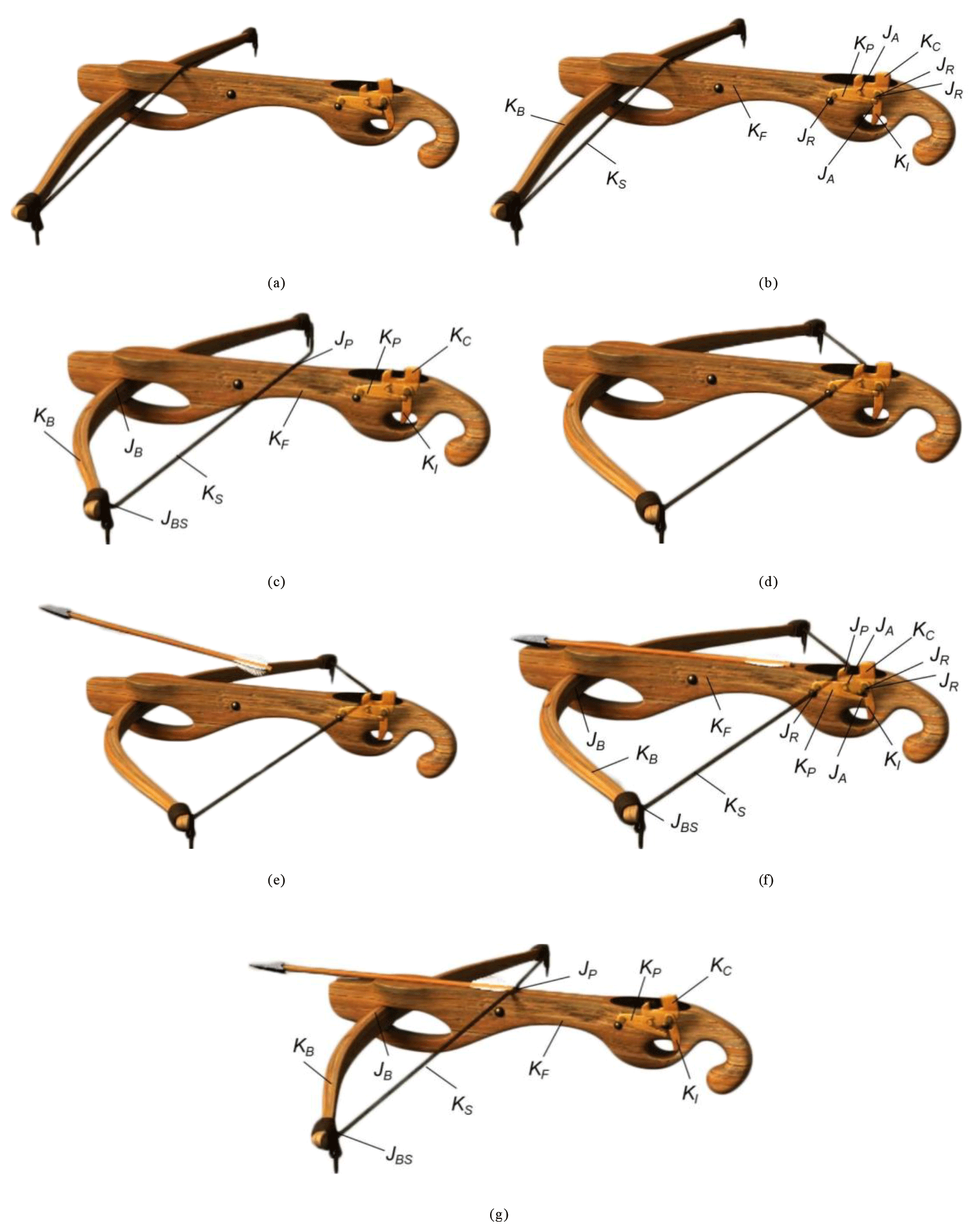
3.2.3 Putting the arrow on the crossbow
When the bowstring is connected to the percussion link, the shooter can put the arrow on the crossbow, as shown in Fig. 3e. In this step, there is no relative motion among all six members.
3.2.4 Releasing the bowstring
When the arrow is ready, the shooter can aim at the target and hopefully achieve precise shooting, as shown in Fig. 3f. When pressing the input link, the input link is adjacent to the frame and the connecting link with a revolute joint JR and a cam joint JA, respectively. The percussion link is adjacent to the frame and the connecting link with a revolute joint JR and a cam joint JA, respectively. The connecting link is adjacent to the frame with a revolute joint JR. The bowstring is attached to the percussion link. The relative motion between two incident members is the translation along an axis. Therefore, the joint incident to the bowstring and the percussion link can be considered a prismatic joint JP. The bow is adjacent to the frame and the bowstring with a bow joint JB and a bowstring joint JBS, respectively. The corresponding topology matrix is shown in Fig. 4c. When the bowstring has been released, the operation enters the final step.
The operation of this step consists of six members, three revolute joints, one bow joint, one bowstring joint, one prismatic joint, and two cam joints. Therefore, NL=6, CpR=2, NJR=3, CpB=2, NJB=1, CpBS=2, NJBS=1, CpP=2, NJP=1, CpA=1, and NJA=2. The number of degrees of freedom, Fp, of this step is
Therefore, the motion of this step is constrained.
3.2.5 Shooting the arrow
At this step, through the elasticity of the bow and the bowstring, the arrow starts to be forced. Until the arrow is shot, the bow and the bowstring return to the former position and the function cycle will be periodically continued. In addition, the input link, the percussion link, and the connecting link can be treated as being incorporated into the frame, as shown in Fig. 3g. The bow is adjacent to the frame and the bowstring with a bow joint JB and a bowstring joint JBS, respectively. The bowstring is adjacent to the frame with a prismatic joint JP. The corresponding topology matrix is shown in Fig. 4d.
The trigger mechanism uses the perfect geometric and kinetic relations of the frame, the input link, the percussion link, and the connecting link to hook the bowstring and keep the elasticity of the bowstring, facilitating the archer's accuracy. This result is that it maximizes the accuracy of this weapon.

4.1 Structural analysis
With these improvements in accuracy, people then attempted to increase the efficiency of arrow shooting. It is believed that the repeating crossbow dates back to 400 BC because a repeating crossbow was excavated in Jiangling, Hubei, dating back to this time. Because the region where it was unearthed was the territory of the Chu State in the Warring States Period, it was named the Chu State repeating crossbow. This crossbow is shown in Fig. 5. It is a reconfigurable mechanism with six members (Hsiao and Yan, 2012), including the frame (member 1, KF), a bow (member 2, KB), a bowstring (member 3, KS), an input link (member 4, KI), a percussion link (member 5, KP), and a connecting link (member 6, KC). The magazine is fixed on the top of the frame, holding 20 arrows, which are placed in order on the two barrels. There is a channel in the frame so that the trigger mechanism can slide on the channel. The trigger mechanism consists of an input link, a percussion link, and a connecting link. There is a switch point at the back limit of the channel. When the input link is pulled and the percussion link touches the switch point, the arrows can be shot. The Chu State repeating crossbow is a small handheld weapon which is less than 30 cm long. Its bow is composed of a short piece of wood on both sides. Therefore, its projectile force depends mainly on the stretchy bowstring. Arrows are shot with the elasticity of the bowstring. It is deducible that the Chu State repeating crossbow is not very powerful. It can only shoot arrows to a distance of 20 to 25 m, which is why it is regarded as a handheld weapon used for game and bird shooting.
Although the Chu State repeating crossbow is not an actual weapon, its design is very ingenious, with many clever features. Regarding its mechanism, by simply pushing the input link (which is at the rear part of it) back and forth, the arrows in the magazine drop in order to allow the shooting of 20 arrows in 10 shots. As the arrows are shot, one just needs to push the input link forward, and the connecting link hooks the bowstring in front of the frame. Then, the percussion link's head will lift to balance its own weight, positioning itself in the groove of the connecting link again. As it is pulled back, the preparation for the next shot is complete. With this mechanical structure, the Chu State repeating crossbow can shoot arrows repeatedly. Nevertheless, there is no historic document that writes about the Chu State repeating crossbow.
4.2 Shooting process
The Chu State repeating crossbow can finish all shooting processes by handling the input link. Since its arrows are affected by gravity, the shooting process includes four steps: preparing to hook the bowstring, stretching the bowstring, releasing the bowstring, and shooting the arrow. Each step is described as follows.
4.2.1 Preparation in order to hook the bowstring
The first step in the shooting process is to prepare to hook the bowstring. The frame, the bow, and the bowstring are temporarily immovable. The input link is pushed forward and is adjacent to the connecting link with a revolute joint JR. The percussion link is adjacent to the input link and the connecting link with a revolute joint JR and a cam joint JA, respectively. The corresponding 3D model and topology matrix are shown in Figs. 6a and 7a, respectively. When the bowstring is hooked, as shown in Fig. 6b, the operation enters the second step.
The operation of this step consists of three members, two revolute joints, and one cam joint. Therefore, NL=3, CpR=2, NJR=2, CpA=1, and NJA=1. The number of degrees of freedom, Fp, of this step is
Therefore, the motion of this step is constrained.
4.2.2 Stretching the bowstring
When the input link reaches the front limit of the channel, the bowstring is caught by the connecting link in order to be stretched. Then, the input link is pulled backward and is adjacent to the frame with a prismatic joint JP. The bow is adjacent to the frame and the bowstring with a bow joint JB and a bowstring joint JBS, respectively. The bowstring is stretched by the connecting link directly. There is no relative motion between them. Therefore, the joint incident to the bowstring and the connecting link can be considered a direct contact JD. In the meantime, the input link, the percussion link, and the connecting link have no relative motion and are integrated into the same member. The corresponding 3D model and topology matrix are shown in Figs. 6c and 7b, respectively.
4.2.3 Releasing the bowstring
When the input is at the back limit of the channel, the percussion link touches the switch point and starts to release the bowstring, as shown in Fig. 6d. Since the percussion link is an irregular shape like a cam, the joint incident to the percussion and the frame (switch point) can be considered a cam joint JA. The input link is adjacent to the frame and the connecting link with a prismatic joint JP and a revolute joint JR, respectively. The percussion link is adjacent to the input link and the connecting link with a revolute joint JR and a cam joint JA, respectively. The bowstring is attached to the connecting link. The relative motion between two incident members is the translation along an axis. Therefore, the joint incident to the bowstring and the connecting link can be considered a prismatic joint JP. The bow is adjacent to the frame and the bowstring with a bow joint JB and a bowstring joint JBS, respectively. The corresponding 3D model and topology matrix are shown in Figs. 6e and 7c, respectively.
The operation of this step consists of six members, two revolute joints, one bow joint, one bowstring joint, two prismatic joints, and two cam joints. Therefore, NL=6, CpR=2, NJR=2, CpB=2, NJB=1, CpBS=2, NJBS=1, CpP=2, NJP=2, CpA=1, and NJA=2. The number of degrees of freedom, Fp, of this step is
Therefore, the motion of this step is constrained.
4.2.4 Shooting the arrow
When the bowstring has separated from the connecting link, two arrows are shot by the elasticity of the bow and the bowstring. In this step, the input link, the percussion link, and the connecting link have no function and wait for the next shot. The bow is adjacent to the frame and the bowstring with a bow joint JB and a bowstring joint JBS, respectively. The bowstring is adjacent to the frame with a prismatic joint JP. The corresponding 3D model and topology matrix are shown in Figs. 6f and 7d, respectively.
Crossbows were important weapons and evolved from the traditional bow in ancient China. Since the topological structures change during the shooting process, crossbows are reconfigurable mechanisms. It is not easy to realize clearly the structural variations in the operation. This paper analyzed two different kinds of crossbows: the original crossbow and the Chu State repeating crossbow. The original crossbow was used in very early times, covering a very wide terrain. It was also found among many excavated relics and mentioned in many historical documents. The Chu State repeating crossbow was the earliest repeating crossbow in China. However, it has not been mentioned in any historical documents. Rather, it is deduced to be a toy of personal invention. Applying the concept of the topological matrix, the topological variabilities of crossbows have been described. The degrees of freedom of crossbows are discussed and the motion is constrained during operation. In addition, the shooting process of crossbows is illustrated with 3D computer graphics to explain the movements of its topological structure.
The data are available upon request from the corresponding author.
JD was the lead author and provided the material of the Mongolian traditional bow. KS directed the analysis of the model represented in the paper. YZ structured the paper. T made contributions to presentation approaches for the mechanisms. YAY provided reviews of the paper.
The authors declare that they have no conflict of interest.
The authors are grateful to the Inner Mongolia Autonomous Region Grassland Elite (Hohhot, China) under grant CYYC5027 for the financial support of this work.
This research has been supported by the Inner Mongolia Autonomous Region Grassland Elite (grant no. CYYC5027).
This paper was edited by Daniel Condurache and reviewed by three anonymous referees.
Hsiao, K. H.: Structural Synthesis of Ancient Chinese Original Crossbow, T. Can. Soc. Mech. Eng., 37, 259–271, https://doi.org/10.1139/tcsme-2013-0016, 2013.
Hsiao, K. H. and Yan, H. S.: Structural Synthesis of Ancient Chinese Chu State Repeating Crossbow, Advances in Reconfigurable Mechanisms and Robots I, 749–758, https://doi.org/10.1007/978-1-4471-4141-9_67, 2012.
Hsiao, K. H. and Yan, H. S.: Mechanisms in Ancient Chinese Books with Illustrations, 1st Edn., Springer, Switzerland, 2014.
Jingzhou Museum: Important Archaeological Discoveries, Cultural Relics Press, Beijing, 2009.
Liu, X. Z.: History of Inventions in Chinese Mechanical Engineering, 1st Edn., Science Press, Beijing, 1962 (in Chinese).
Lu, J. Y.: History of Chinese Machinery, 1st Edn., Ancient Chinese Machinery Cultural Foundation, Beijing, 2003 (in Chinese).
Lu, J. Y. and Hua, J. M.: A History of Science and Technology in China, Volume of Mechanical Engineering, Science Press, Tainan, 2000 (in Chinese).
Mao, T. Y.: Treatise on Armament, 1st Edn., Hainan Press, Hainan, 2001 (in Chinese).
Needham, J.: Science and Civilisation in China, Vol. 5, Part 6, Cambridge University Press, Cambridge, 1954.
Shi, K., Zhang, Y., Lin, J. L., and Hsiao, K. H.: Ancient Chinese Maze Locks, T. Can. Soc. Mech. Eng., 41, 433–441, https://doi.org/10.1139/tcsme-2017-0030, 2017.
Shi, K., Hsiao, K. H., Zhao, Y., Huang, C. F., and Xiong, W. Y.: Structural Analysis of Ancient Chinese Wooden Locks, Mech. Mach. Theory., 146, 1–13, https://doi.org/10.1016/j.mechmachtheory.2019.103741, 2020.
Xu, Z. Y.: Trigger Mechanism, 1st Edn., Hebei Fine Arts Publishing House, Hebei, 2007 (in Chinese).
Yan, H. S.: Creative Design of Mechanical Devices, 1st Edn., Springer, Beijing, 1998.
Yan, H. S. and Kuo, C. H.: Representations and identifications of structural and motion state characteristics of mechanisms with variable topologies, T. Can. Soc. Mech. Eng., 30, 19–40, https://doi.org/10.1117/12.716354, 2006.
Zhang, C. H., You, Z. H., Wu, Z. Z., and Liu, Y. L.: History of Inventions in Chinese Mechanical Engineering, 2nd Edn., Tsinghua University Press, Beijing, 2004 (in Chinese).
Zhong, S. Y.: History of Military Affairs and Engineering Technology in Ancient China, Shanxi Education Publishing House, Shanxi, 2008 (in Chinese).