the Creative Commons Attribution 4.0 License.
the Creative Commons Attribution 4.0 License.
 | 28 Oct 2020
Thickness-utilizing deployable hard stops for origami-based design applications
David W. Andrews
Spencer P. Magleby
Larry L. Howell
This work develops and presents design concepts and models of thickness-utilizing deployable hard stops (ThUDS) which can be incorporated into origami-based design applications to provide stability in specific fold states. A ThUDS, like a lamina-emergent mechanism, emerges from a flat state and can reside within a sheet. A variety of planar and spherical ThUDS configurations are developed and presented, using diagrams, equations, and prototypes. Examples of ThUDS applications are given and attributes are discussed. Considerations for the design of a ThUDS are discussed. This work outlines how a ThUDS can maintain foldability while improving stability and utilizing thickness. Parameter values for prototypes are also given for reader reproduction.
- Article
(22198 KB) - Full-text XML
- BibTeX
- EndNote


Origami has found uses in numerous engineering and design applications such as small soft robots (Banerjee et al., 2018), DNA mechanisms (Su et al., 2017), transformable metamaterials (Yang and You, 2018), energy absorbers (Ma et al., 2019), and an optimized jumping mechanism (Sadeghi et al., 2019). In many applications, such as those seen in current origami-based products on the market, it is necessary to block motion and provide stability in a desired configuration (Avila et al., 2019).
Greenwood et al. (2020) developed a method for determining which techniques could be used to stabilize an origami pattern or origami-inspired device. Suggested techniques include using strain energy (Yasuda et al., 2016), compliant mechanisms (Zhang et al., 2019), and heating (Deng and Chen, 2015). Yasuda et al. (2019) recently proposed programmable structures for obtaining stability under a load. Multiple different methods were suggested by Yellowhorse and Howell (2018) for providing stiffness in origami-inspired designs. Other stiffness-based methods include using coupled origami tubes (Filipov et al., 2015, 2019), stacking origami patterns (Fang et al., 2018), and origami-tube interleaving (Cheung et al., 2014). Generally, these methods act at the joints or add increased complexity to the system.
In previous work, the authors developed two categories of deployable transcrease hard stop models that block the motion of an origami pattern in a desired fold state while maintaining the original crease locations (Andrews et al., 2019). Transcrease refers to the hard stops lying across the crease. Deployable transcrease hard stops implement cuts into the origami, making it kirigami (sometimes referred to as “pop-up origami”; Bernard et al., 2018). Since these models were developed for origami, they are based on the zero-thickness assumption of paper. Therefore, they cannot be directly implemented in origami-based applications without accommodating for thickness.
Various thickness-accommodation techniques have been developed for adapting origami designs to thicker materials (Morgan et al., 2016; Lang et al., 2018). Tachi (2011) developed an early technique that allowed for foldability while maintaining the kinematics of the original origami pattern. Chen et al. (2015) outlined equations for calculating panel thicknesses based on spherical linkages. Ku and Demaine (2016) developed algorithms to aid in developing folding patterns in thick materials. Later, Ku (2017) developed a technique that strategically removes material on both sides of a crease, allowing panels to fold to a specified angle. A technique using linkages at the joints was also recently created (Lang et al., 2020). Butler et al. (2020) developed a technique that incorporates compliant sheets. These techniques usually involve the strategic removal or arrangement of material to enable folding.
The developments presented in this paper represent a transition from accommodating thickness to utilizing thickness. Ku (2017) started down this path by developing a technique that blocks motion at dihedral angles less than 90∘ through adjusting the removal of material near the joint. This paper continues to utilize thickness by illustrating thickness-utilizing deployable hard stops (ThUDS), which allow motion to be blocked at any angle and obtain stability. Two categories of ThUDS are outlined that block motion of a moving joint at a specified angle. A general form is given for each category, followed by special cases and adaptations. Diagrams and physical examples are given for each category. Finally, examples are given to show applications for ThUDS.
Thickness-utilizing deployable hard stops (ThUDS) are mechanisms that are designed to block motion at a desired angle using self-interference. ThUDS utilize the thickness of the material to assist with motion blocking and stability within folded systems. This primarily occurs through surface contact between contacting links, which can occur in multiple directions. Similar to lamina-emergent mechanisms (LEMs; Jacobsen et al., 2010), ThUDS originate in a flat, planar state and are deployed to be a functional, 3D structure. Because of this, ThUDS have direct applications in origami-based systems, with the ability to add necessary stability while allowing for folding.
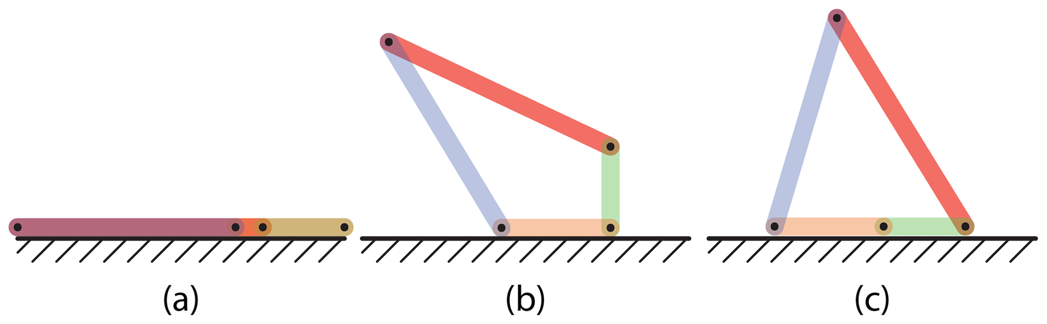
Figure 1Theoretical diagram of ThUDS in (a) flat, (b) deploying, and (c) blocked deployed states.
Figure 1 depicts how this works. Figure 1a shows the mechanism in its flat, initial state, Fig. 1b shows the ThUDS deploying, and Fig. 1c shows the mechanism in its final, blocked state. The colors of each link refer to a specific portion of the mechanism, as follows:
-
orange – ground link
-
blue – blocked link
-
red – stabilizing link
-
green – interfering link.
In practice, the ground link is extended beyond the joint, such that the green interfering link comes in contact with it at the end of its motion (typically 180∘). Other angles could be used but would require additional material thickness to accommodate the decreased interference angle.
ThUDS can be separated into two categories, namely deploying strut and sector panel. The deploying strut ThUDS category has two subcategories, namely planar and spherical. They are developed from the general planar transcrease hard stop (PTHS) model for zero-thickness deployable transcrease hard stops (Andrews et al., 2019). A sector panel ThUDS is similar to self-blocking degree-4 origami vertices (Foschi and Tachi, 2018) with panels (like origami facets) rather than discrete links. They are developed from the general spherical transcrease hard stop (STHS) model for zero-thickness deployable transcrease hard stops (Andrews et al., 2019).
In the following sections the general form of each category is outlined using diagrams and examples. Examples were 3D printed and assembled with tape joints. Special cases and adaptations for each are also presented. Special cases refer to adjusting the general equations, such as for obtaining flat foldability, whereas adaptations refer to changing the general definition for various reasons, such as inverting motion.
Planar and spherical deploying strut ThUDS are illustrated using diagrams, equations, and examples. Parameter values for the examples are given in Appendix A in Tables A1 (planar) and A2 (spherical).
3.1 Planar deploying strut ThUDS
A planar deploying strut ThUDS is a self-interfering four-bar mechanism that blocks motion in a desired state and is defined by the following:
where ρd is the dihedral angle, θ is the strut angle, L1−L4 are link lengths, d1−d6 are joint offsets (positive directions shown), and P1−P4 are joint reference planes. Dimensions and reference planes (dashed lines) are depicted in Fig. 2. Joints are denoted as J12, J23, J34, and J41, which are shown in Fig. 3 for 3D reference. Each joint offset relates a joint to a joint reference plane, with J41 constrained to be located on P1 to reduce the number of joint offset parameters from 8 to 6. It can be helpful, but not necessary, to use external surfaces as joint reference planes (see Fig. 2b).

Figure 2General diagram for a planar deploying strut ThUDS with key parameters shown. Showing side views in the (a) deployed and (b) flat states. Dashed lines designate joint reference planes. Joint offset (d) arrows denote the parameter's (P) positive direction.

Figure 3Example of a planar deploying strut ThUDS with joints J34 and J41 on the top surface and joints J12 and J23 on the bottom surface. Shown in flat and deployed states. Joint names shown for reference.
Equation (2) is derived using a complex vector loop beginning at J41 and moving clockwise. This single equation results in two solvable equations by employing Euler's formula (; Howell, 2001).
In practice, one would select values for the dihedral angle, two of the link lengths, and all joint offsets while the values for the two remaining link lengths and strut angle are calculated.
Any joint offset value may be used. This can result in links 3 and 4 not being parallel to links 1 and 2 in the flat state (see Fig. 2b). Figure 4 shows an example of a 0.5 in. (12.7 mm) thick planar deploying strut ThUDS with joint offset values arbitrarily selected, such that J34 protrudes beyond the upper surface in the flat state.

Figure 4Planar deploying strut ThUDS with arbitrary joint offsets. Shown in flat and deployed states.
For all links to be parallel in the flat state and reside completely within the thickness, as shown in Fig. 3, the joint offset values must form a closed loop, such that the following applies:
This would also result in parallel joint reference frames.
Joint offset values can be selected to allow for loads to be carried though the links and thus bypass the joints using the isolation principle (Guérinot et al., 2005). In this way, the material thickness is being utilized by creating surface contact between links. An example of this is shown in Fig. 3, where joints J12 and J23 are placed on the bottom surface and joints J34 and J41 are placed on the top surface. This allows link L4 to rotate 180∘ before interfering with link L1, while also allowing for contact between all other pairs of adjacent links.
3.2 Spherical deploying strut ThUDS
A curved version of a planar deploying strut ThUDS, Fig. 5 diagrams a general spherical deploying strut ThUDS, which is defined by Eq. (3) and the following:
where ρd is the dihedral angle, α1−α4 are the link sector angles, β is the total ground sector angle, and d1−d6 are joint offsets. Intermediate variables ϕ2, ϕβ, ξ2, ξ3, and ξbeta used in Eq. (6) are defined by the following:
where ϕ2 and ϕβ represent joint offset angles, and ξ2, ξ3, and ξβ represent equivalent link sector angles. Joint reference planes are defined in the same way as in the planar subcategory (see Fig. 2b). Joints are denoted in Fig. 6 for 3D reference.

Figure 5General diagram for a spherical deploying strut ThUDS with key parameters shown. Showing (a) the projection of the outer surface (isometric view) in the deployed state and (b) the flat state from above. Dashed lines in (b) show the position of link 4 in the deployed state. Joints rotate about O.
The joint offset values are defined on the surface of a cylinder of radius, r, within which the spherical deploying strut ThUDS is defined (see Fig. 5b). It is important to note that the joint axis for each joint must pass through a single point (O) at the center of this cylinder, thus maintaining the spherical deploying strut ThUDS as a spherical mechanism.

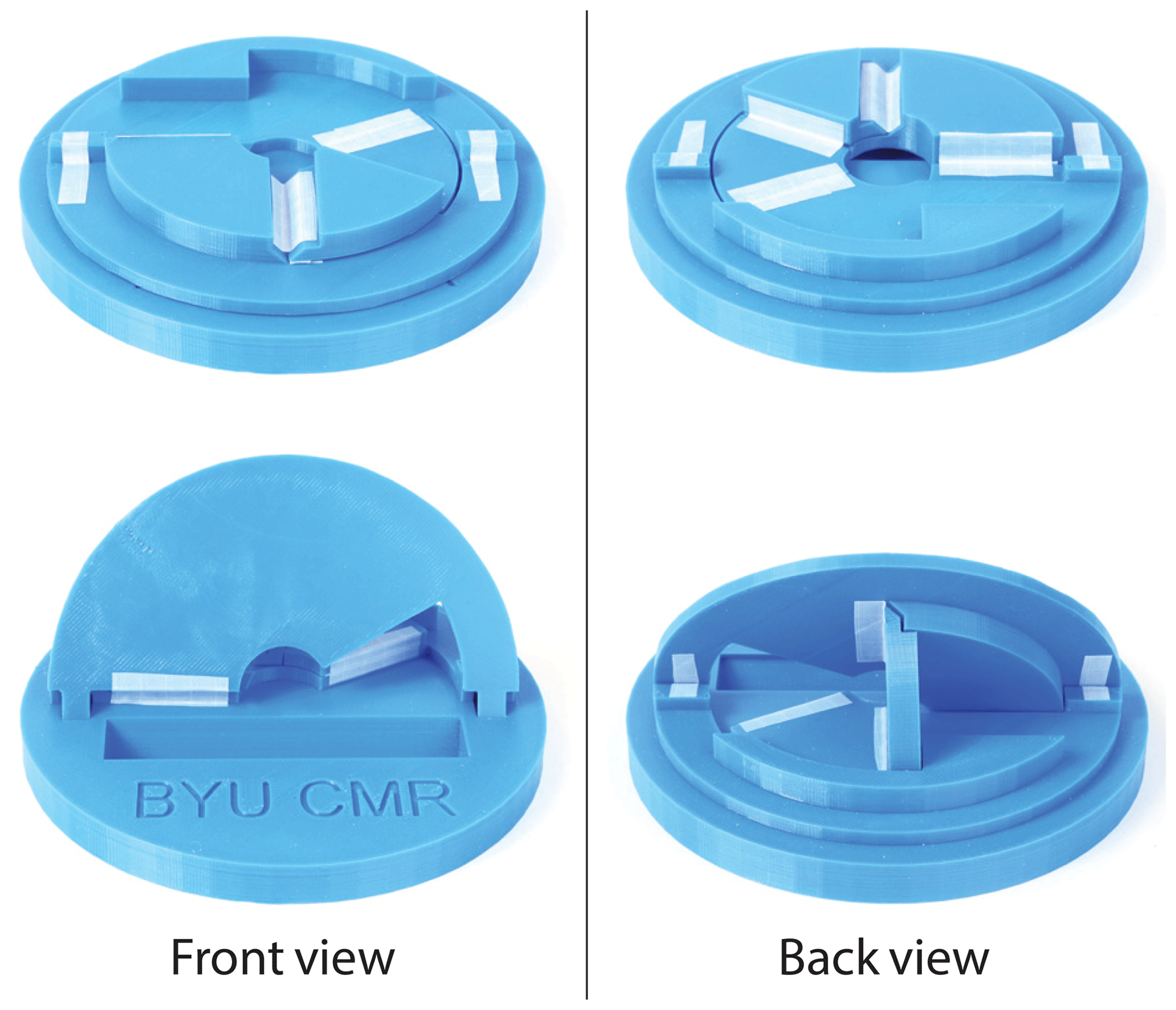
Figure 6Example of a spherical deploying strut ThUDS. Shown in flat and deployed states. Joint names shown for reference.
Figure 6 shows a general example of a spherical deploying strut ThUDS. Joints J12 and J23 lie on the base surface, and joints J34 and J41 lie on the upper surface, which is at an angle with respect to the base surface. Contact is created between each pair of adjacent links (compare to Fig. 3).
In practice, one would select values for the dihedral angle, two of the sector angles (α1−α4, β), and all joint offsets while the values for the three remaining sector angles are calculated along with the five intermediate angles. A nonlinear solver may be required.
3.3 Special case: thickened PTHS model
In some instances it is desirable to simplify a deploying strut ThUDS, such as for faster prototyping or simpler manufacturing. By placing all the joints on the same plane (setting d1 through d6 to be 0), Eq. (2) becomes the following:
and Eq. (6), for the spherical case, reduces to the following:
with no intermediate variables needing to be calculated.
This simplification creates this special case, which is simply a thickened version of the PTHS model (Andrews et al., 2019), with link lengths or sector angles measured on the model joint plane.
Figure 7 shows a physical example of a thickened PTHS model planar deploying strut ThUDS, which is based on the general PTHS model. A similar spherical example is shown in Fig. 8. Both examples have the same dihedral angle of 60∘. In these examples, thickness is added in a single direction. Thickness can be utilized by adding material both above and beneath the joint plane, creating additional surface contact between the links.

Figure 7A simplified planar deploying strut ThUDS based on the general PTHS model (Andrews et al., 2019). Shown in flat and deployed states.
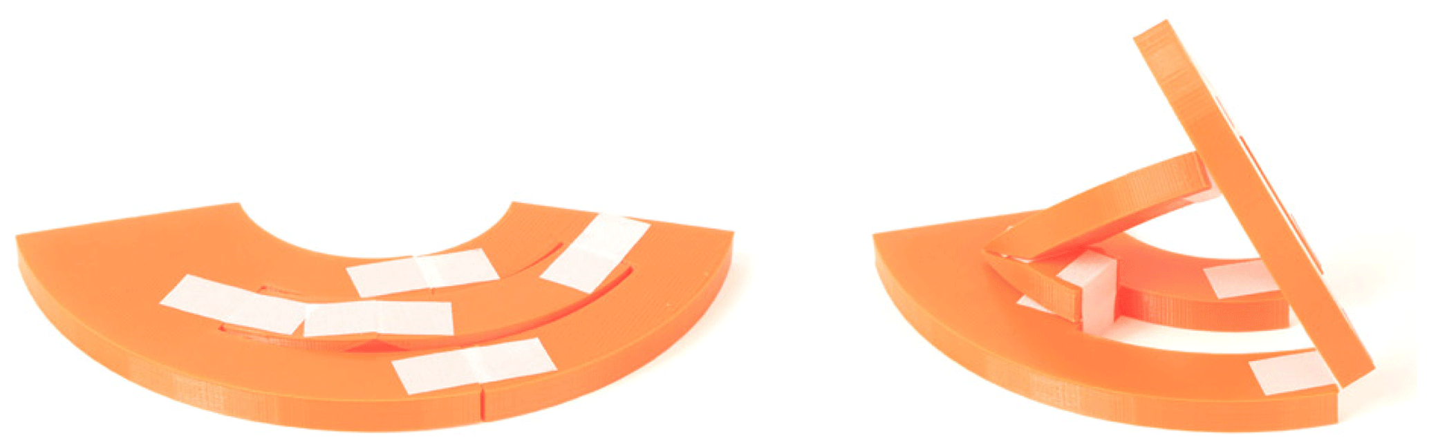
Figure 8A simplified spherical deploying strut ThUDS based on the general PTHS model (Andrews et al., 2019). Shown in flat and deployed states.
3.4 Special case: flat-foldable, deploying strut ThUDS
In origami, a crease is flat foldable if it can obtain a fold angle of ±π (Lang et al., 2018). For a deploying strut ThUDS, flat foldability is possible when a set of collinear joints exist on an exterior surface, requiring that Eq. (3) be satisfied.
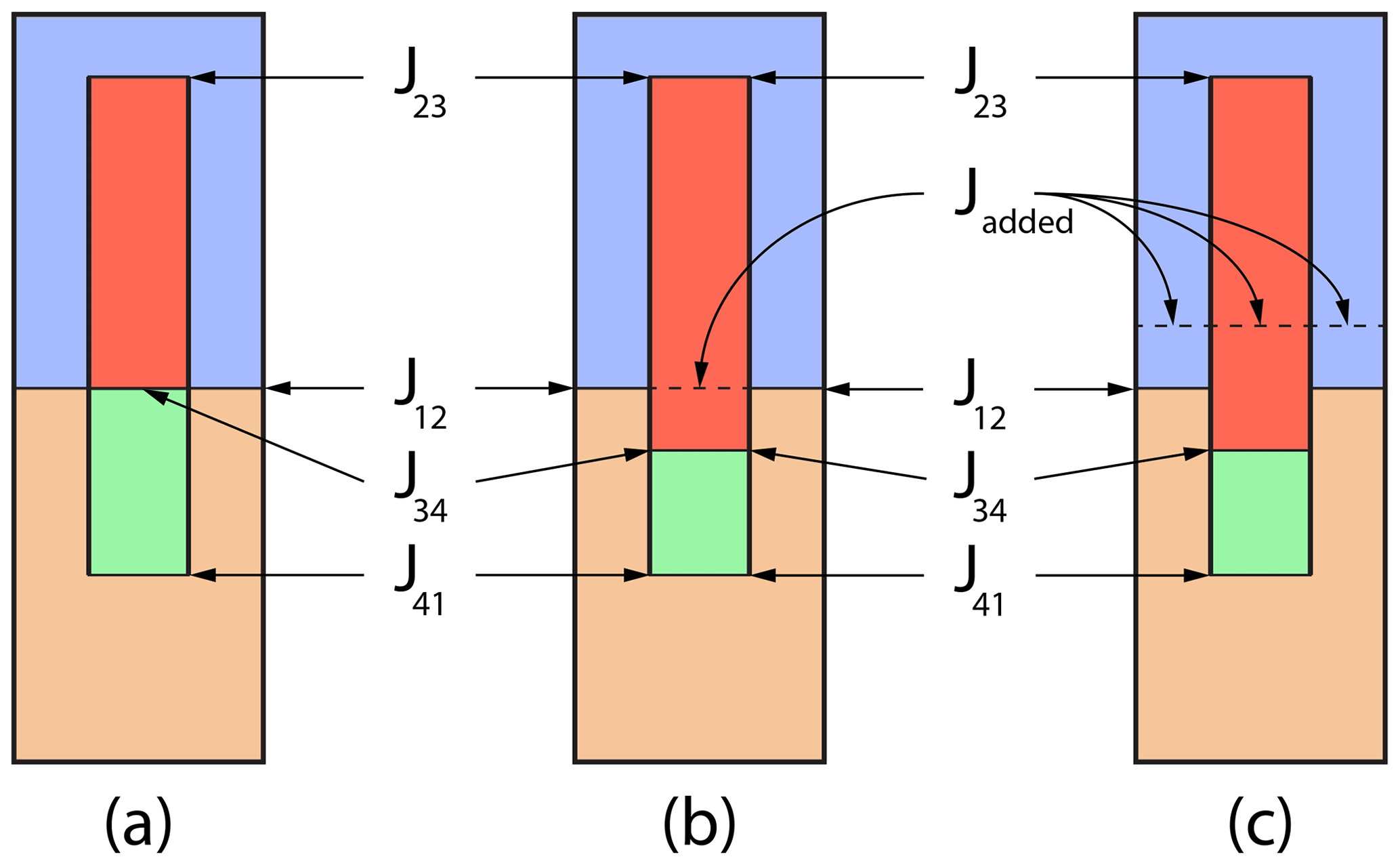
This special case is important because of the three particular states that are possible, namely flat folded, flat, and deployed. Three techniques for achieving these states are outlined below and illustrated in Fig. 9, with Jadded referring to added joints. A spherical example is only given for the first technique, though the other techniques can be similarly applied.
3.4.1 Joint alignment
The simplest way of achieving flat foldability is aligning joints J12 and J34 (see Fig. 9a). For the planar subcategory, this means that L1=L4 and L2=L3. For the spherical subcategory, this means that α1=α4 and α2=α3. These joints can be aligned on either outer surface. A planar example of this flat-foldable technique is shown in Fig. 10, where the collinear joints lie on the bottom surface and flat foldability is in the opposite direction as deployment.

Figure 10Flat-foldable planar deploying strut ThUDS with increased surface contact to improve load carrying. Shown in flat-folded, flat, and deployed states.
Two examples of flat-foldable spherical deploying strut ThUDS using joint alignment are shown in Fig. 11. Fig. 11a gives a simple version with all joints on the same plane, whereas Fig. 11b shows a more complex example with the joints offset, similar to that shown in Fig. 10, allowing for increased surface contact between the links. Flat foldability is in the same direction as deployment for Fig. 11a and opposite deployment for Fig. 11b.
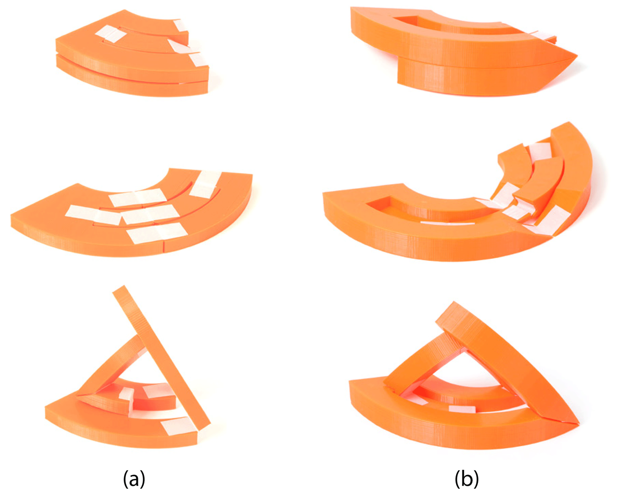
Figure 11Flat-foldable spherical deploying strut ThUDS; (a) a simple example and (b) a more complex example with surface contact. Shown in flat-folded, flat, and deployed states.
This approach is similar to the flat-foldable planar transcrease hard stop (FF-PTHS) model developed previously (Andrews et al., 2019), which works for dihedral angles less than 90∘. By utilizing the material thickness, flat foldability can be obtained with dihedral angles of 90∘ or more. This is accomplished by offsetting joints J23 and J41, thus changing the deploying strut ThUDS kinematics.
F,or example, joint J41 in Figs. 10 and 11b is offset from the bottom surface, whereas the other joints are all on the bottom surface. Additionally, these examples highlight strategically locating the joints and the material thickness to increase surface contact, thus increasing ThUDS stability.
3.4.2 Split strut
By splitting the strut and introducing an additional joint collinear with J12 (see Fig. 9b), dihedral angles of ≥90∘ can be easily obtained. The primary trade-off of this technique is the addition of a degree of freedom and, thus, reduced stability. By strategically placing the joints, the material thickness can be utilized to return some stability.
Figures 12 and 13 show examples of this technique using a planar deploying strut ThUDS. The first has collinear joints on the bottom surface, a dihedral angle of 120∘, and folds flat opposite the direction of deployment. The second has collinear joints on the top surface, a dihedral angle of 90∘, and folds flat in the same direction as deployment.
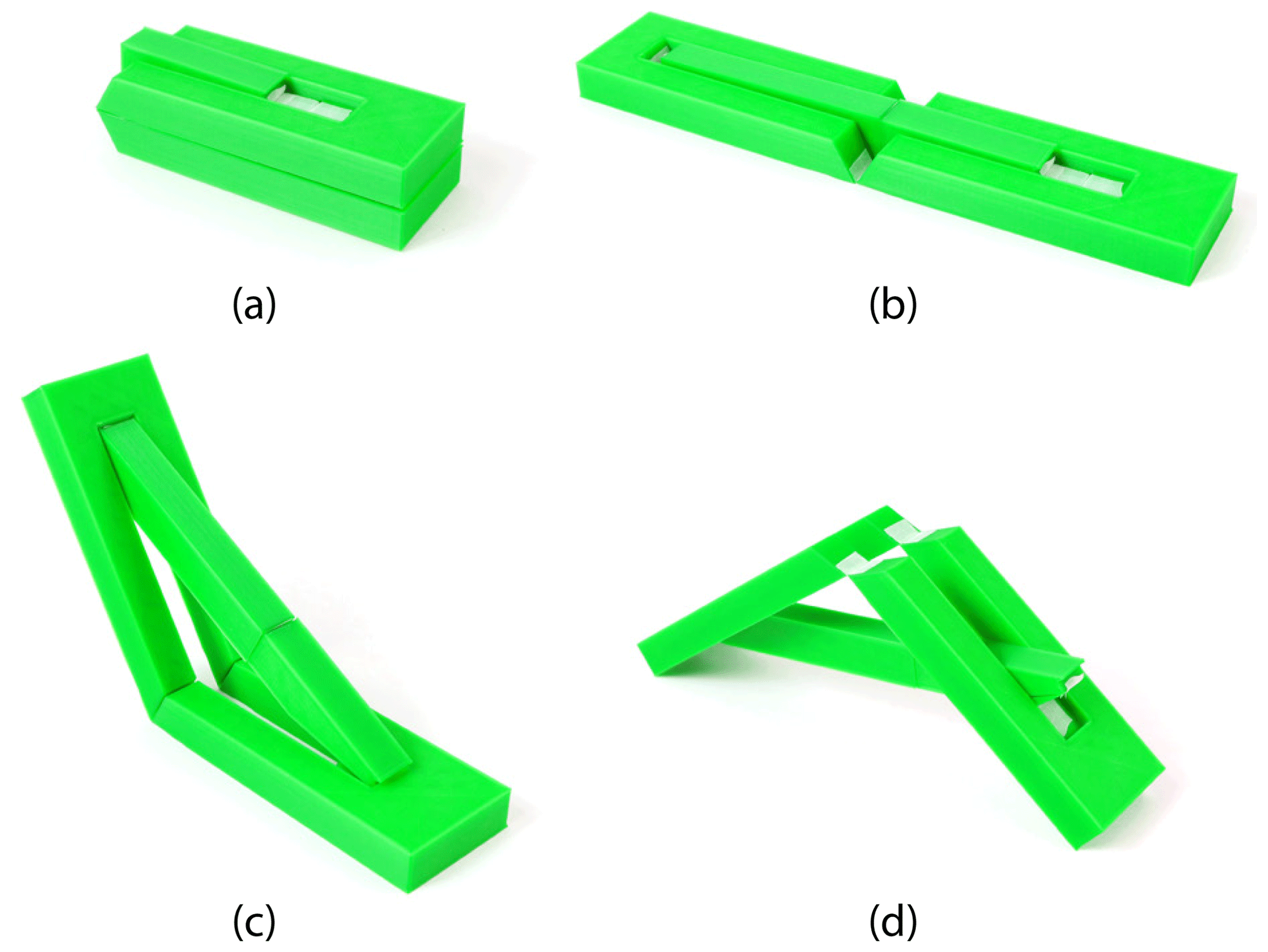
Figure 12Flat-foldable planar deploying strut ThUDS with strut (link 3) split. Shown as (a) flat folded, (b) flat, (c) deployed, and (d) in an undesired state due to the added degree of freedom.
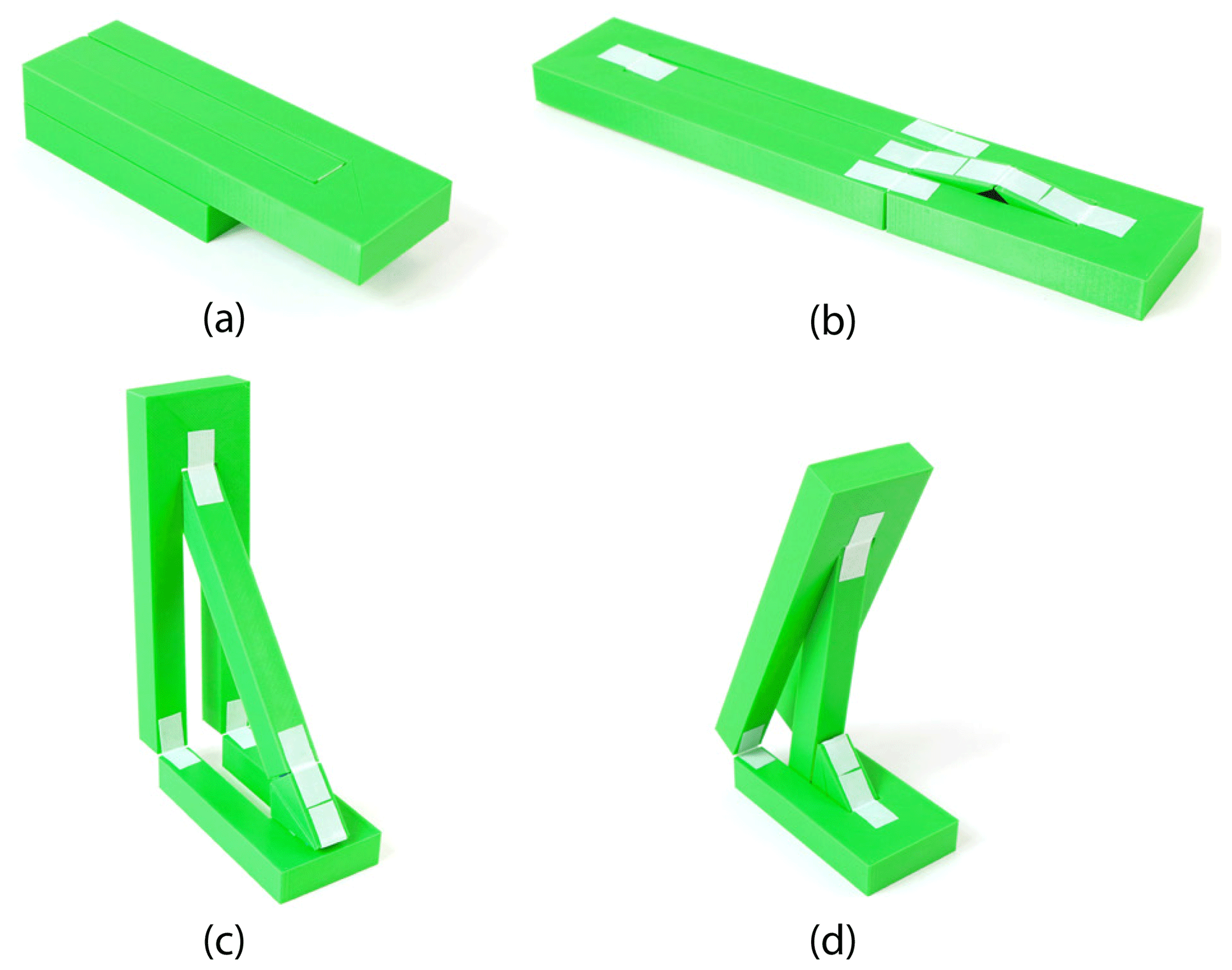
Figure 13Flat-foldable planar deploying strut ThUDS with strut (link 3) split. Shown as (a) flat folded, (b) flat, (c) deployed, and (d) in an undesired state due to the added degree of freedom.
3.4.3 Double-split link
The third technique for obtaining flat foldability is to add two collinear joints by splitting links L2 and L3. This technique is limited by the addition of multiple degrees of freedom. Stability is further reduced from the split-strut technique. As before, material thickness can be utilized to aid with locking at the additional joint.
An example of this technique is depicted in Fig. 14. Here the collinear joints lie on the bottom surface, the dihedral angle is 60∘, and the prototype folds flat opposite the direction of deployment.
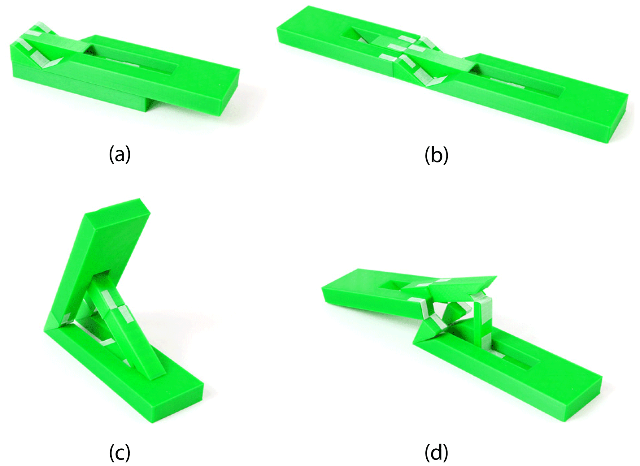
Figure 14Flat-foldable planar deploying strut ThUDS with links 2 and 3 split. Shown (a) flat folded, (b) flat, (c) deployed, and (d) in an undesired state due to the added degrees of freedom.
3.5 Adaptation: addition of offset crease joint
As outlined in Sect. 2, the interfering link (link 4) is constrained to rotate 180∘. For some types of joints, it is infeasible to obtain full 180∘ rotation. This challenge can be overcome by replacing joint J41 with two joints and a link. This is referred to as an offset crease joint (Ku and Demaine, 2016).
Figure 15 diagrams the addition of an offset crease joint to a planar deploying strut ThUDS. Equations (1) and (2) must be adapted to account for this extra joint, which gives the following:
and the updated loop-closure equation is as follows:
where d7 and d8 are joint offsets accounting for the offset crease, and joints J1C and J4C refer to the two joints of the offset crease joint. Joint reference planes are defined in the same way as in Fig. 2b. The material of the link portion of the offset crease joint further helps with blocking the motion.
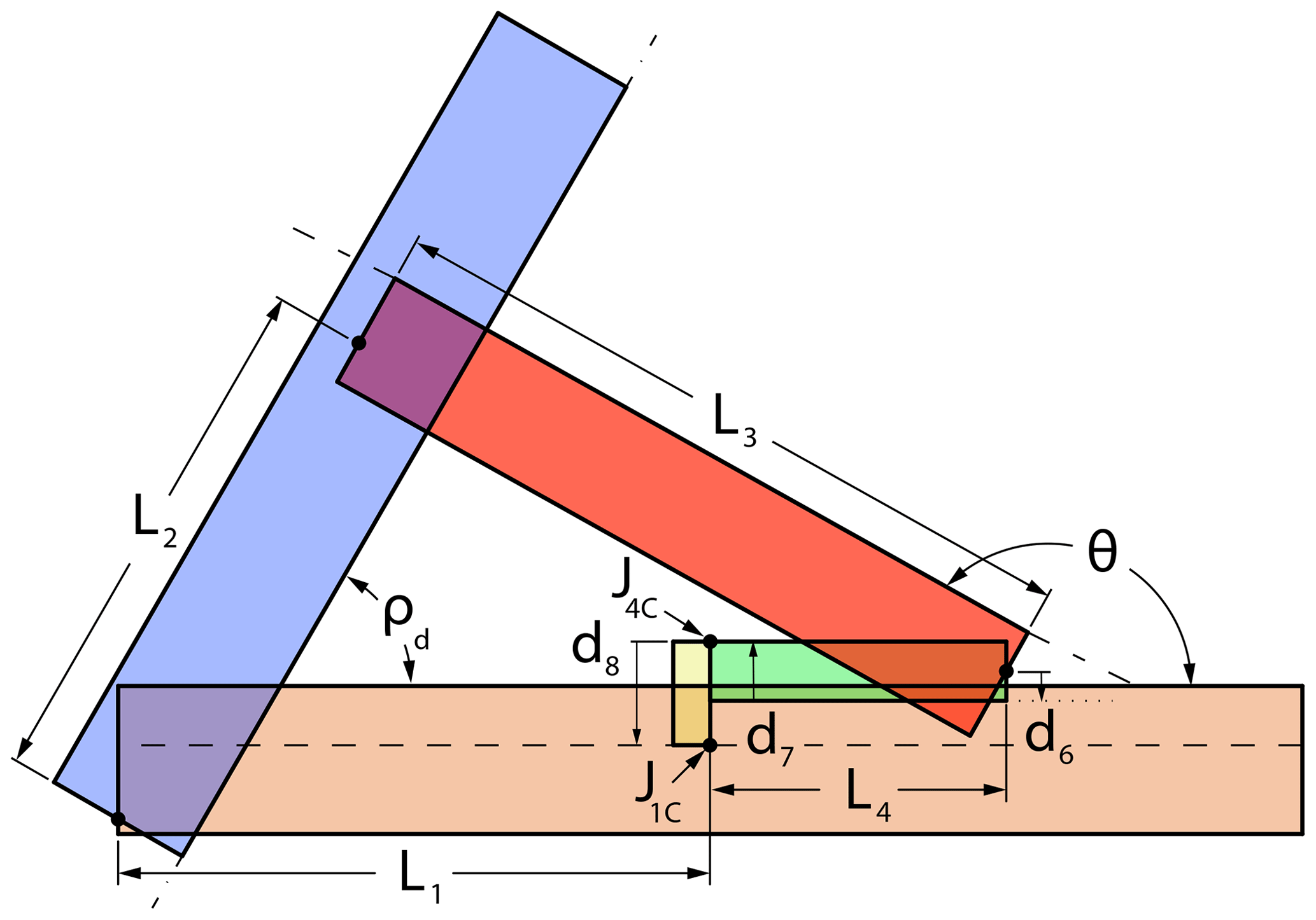
Figure 15Diagram of a planar deploying strut ThUDS with offset crease joint added to depict key parameters, excluding d1−d5 (see Fig. 2). Dashed lines designate joint reference planes.
Figure 16 shows a planar deploying strut ThUDS with an incorporated offset crease joint. In this example, all joints lie on the same plane, parallel to the exterior surfaces, for easier assembly. Adding the offset crease joint allows for surface contact between each pair of connected links, while maintaining simplicity.
Figure 16Planar deploying strut ThUDS with offset crease joint. All joints lie on the center plane. Shown in flat and deployed states.
Following the principles in Sect. 3.4, a deploying strut ThUDS with an offset crease joint can be flat foldable. Figure 17 depicts a flat-foldable ThUDS with an offset crease joint with joint alignment.
Figure 17Flat-foldable planar deploying strut ThUDS with offset crease joint. Flat foldability is in the opposite direction of deployment. All joints lie on the bottom plane. Shown in flat-folded, flat, and deployed states.
3.6 Adaptation: inverted motion
A deploying strut ThUDS is designed to move from a flat, unfolded state to block motion before reaching a flat-folded state. Motion can be inverted such that a deploying strut ThUDS deploys from a flat-foldable state rather than a flat state. For the planar subcategory, this is done by replacing Eqs. (1) and (2) with the following:
and the adjusted loop-closure equation as follows:
with parameters depicted in Fig. 18. Unlike the general case, only four joint offset values are used. This is because the upper surface of link 2 is established as the corresponding joint reference plane, P2 (see Fig. 2b), helping to allow the inverted ThUDS to be flat folded.
Figure 18General diagram for a deploying strut ThUDS with inverted motion depicting key parameters. Dashed lines designate joint reference planes (see names in Fig. 2b).
The design of a deploying strut ThUDS with inverted motion follows the principles outlined earlier. An example of an inverted planar deploying strut ThUDS with surface contact is shown in Fig. 19. Notice that surface contact between L1 and L2 was not established to allow for the desired motion. Contact can be added by extending both links beyond joint J12.
Figure 19Inverted planar deploying strut ThUDS. Flat foldability is in the same direction as deployment. Joint offset values are adjusted to increase surface contact. Shown in flat-folded and deployed states.
A benefit of inverted motion is the ability to be bistable, with flat-folded and deployed stable states. This feature is utilized in the example given in Sect. 5.4.
A sector panel ThUDS is a spherical linkage that utilizes thickness, allowing self-interference to block motion at a specified angle. These are developed from the spherical transcrease hard stop (STHS) model for zero thickness deployable transcrease hard stops (Andrews et al., 2019). See Table A3 in Appendix A for prototype parameters.
The sector panel ThUDS is defined by the following:
where ρd is the dihedral angle, θ1−θ4 are the panel sector angles, and θ12 is the ground sector angle of the spherical triangle when in the deployed state (see Fig. 20).
In practice, one would select values for the dihedral angle and two of the sector angles (θ1−θ4, θ12), while the values for the three remaining sector angles are calculated.
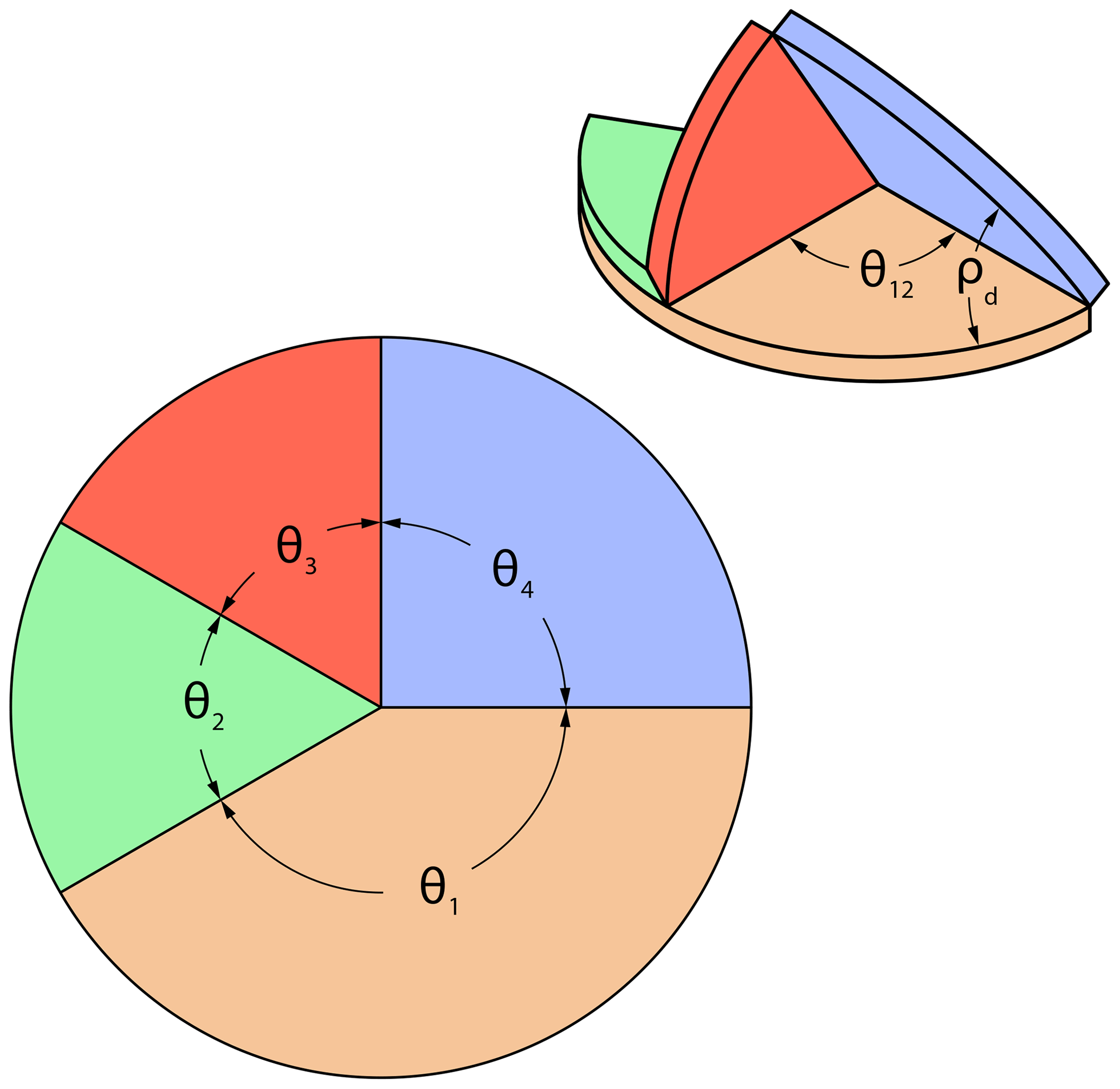
As discussed in Sect. 2, a sector panel ThUDS is like a degree-4 origami vertex, which is a spherical mechanism with all the joints lying on a plane. If the joints are offset, a spherical mechanism becomes a spatial mechanism. The only single degree of freedom four-bar spatial linkage is a Bennett linkage, which has both a flat-foldable and a planar-developable state (Chen et al., 2015). Because a sector panel ThUDS is meant to stop at a desired angle, only one of these two states can be achieved. Therefore, all joints in a sector panel ThUDS must reside on the same plane, though material can be placed on either side of this joint plane.
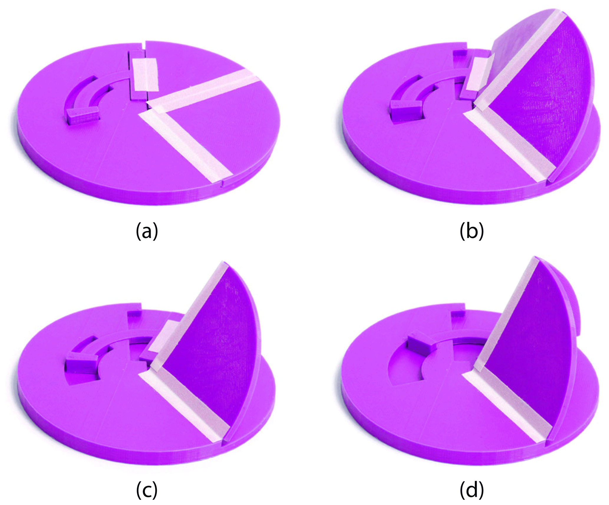
Figure 21 shows two general examples of a sector panel ThUDS, both with the same parameters. The first, Fig. 21a, has thickness added only beneath the joint plane. This example resembles others' work on self-blocking degree-4 vertices (Foschi and Tachi, 2018). The second, Fig. 21b, has thickness added beneath the joint plane, to create panels 1 and 2, and above the joint plane, for panels 3 and 4. This latter case allows for increased surface contact between all pairs of adjacent panels.
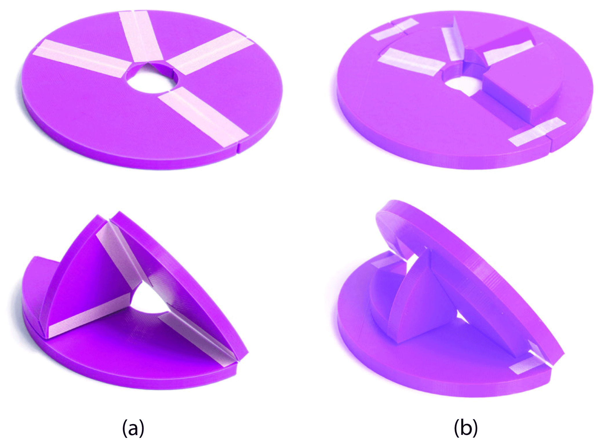
Figure 21Sector panel ThUDS examples with (a) thickness added only beneath the joint plane and (b) thickness added both above and beneath the joint plane. Shown in flat and deployed states.
4.1 Adaptation: tabbed sector panel ThUDS
For a sector panel ThUDS, motion is blocked by self-inference between panels 1 and 3 (see Fig. 20). This requires that panel 2 is able to rotate 180∘ around joint J12, specifying that J12 must reside on the upper surface of panels 1 and 2. This constraint reduces the possible surface contact within the system by constraining the possible positions of the remaining joints.
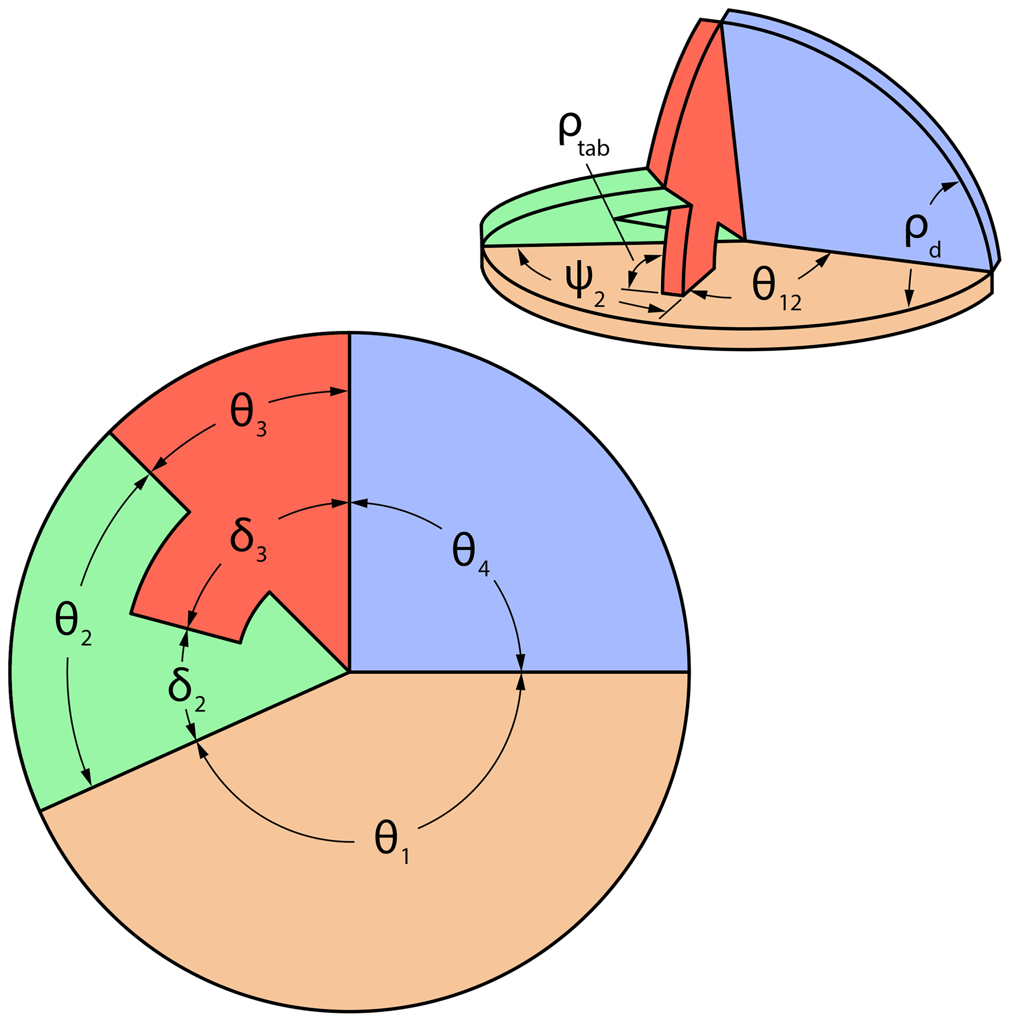
A tabbed sector panel ThUDS alters panels 2 and 3, removing the 180∘ constraint on panel 2 by adding a tab to panel 3, as shown in Fig. 22. The governing equations for this adaptation are Eq. (18) as follows:
where ψ2 is the projection of panel 2 on panel 1, δ3 is the overall stiffener sector angle, δ2 is the tab offset from joint J12, and ρtab is the stiffener angle (see Fig. 22). Other parameters are the same as those defined above. The tabs here are cut along a radial line for convenience, though this does not need to be the case; any shape could be used, as long as the point where δ3 is defined stops parallel to the ground panel plane.
Figure 23 shows an example of a tabbed sector panel ThUDS with a dihedral angle of 60∘, which matches that of the examples in Fig. 21. Material is trimmed on either side of joints J12 and J34 to allow for increased surface contact. Additionally, panel 2 is thinner than the other panels since it is not load-bearing. A notch was added in panel 1 to lock the ThUDS in the blocked state.

Figure 23Tabbed sector panel ThUDS with tab lock groove and panel contact. Shown in flat and deployed states.
Because of solving nonlinearity, the examples shown in Figs. 23 and 24 were designed such that ∘. To aid in design, spherical kinematic equations, such as those given by McCarthy and Soh (2011), can be used in conjunction with the z-direction coupler point equation from Bowen et al. (2014) to determine at what angle the tab will interfere with panel 1.
4.1.1 Special case: flat-foldable sector panel ThUDS
As with a deployable strut ThUDS, flat foldability can be achieved for a sector panel ThUDS if, and only if, a pair of collinear joints exist on an exterior surface. This can be stated symbolically as follows:
In general, this can only occur for a dihedral angle of 90∘ with , thus allowing either θ1, θ2, or θ12 to be selected and the other two calculated.
Unlike the general case, which can only be flat foldability for one dihedral angle, a tabbed sector panel ThUDS can achieve flat foldability for a wider range of dihedral angles, specifically 90∘ ∘. This is possible because the support panel's sector angle is based on δ3 instead of θ3 and δ3>θ3. Figure 24 shows an example of a flat-foldable tabbed sector panel ThUDS with a dihedral angle of 120∘.
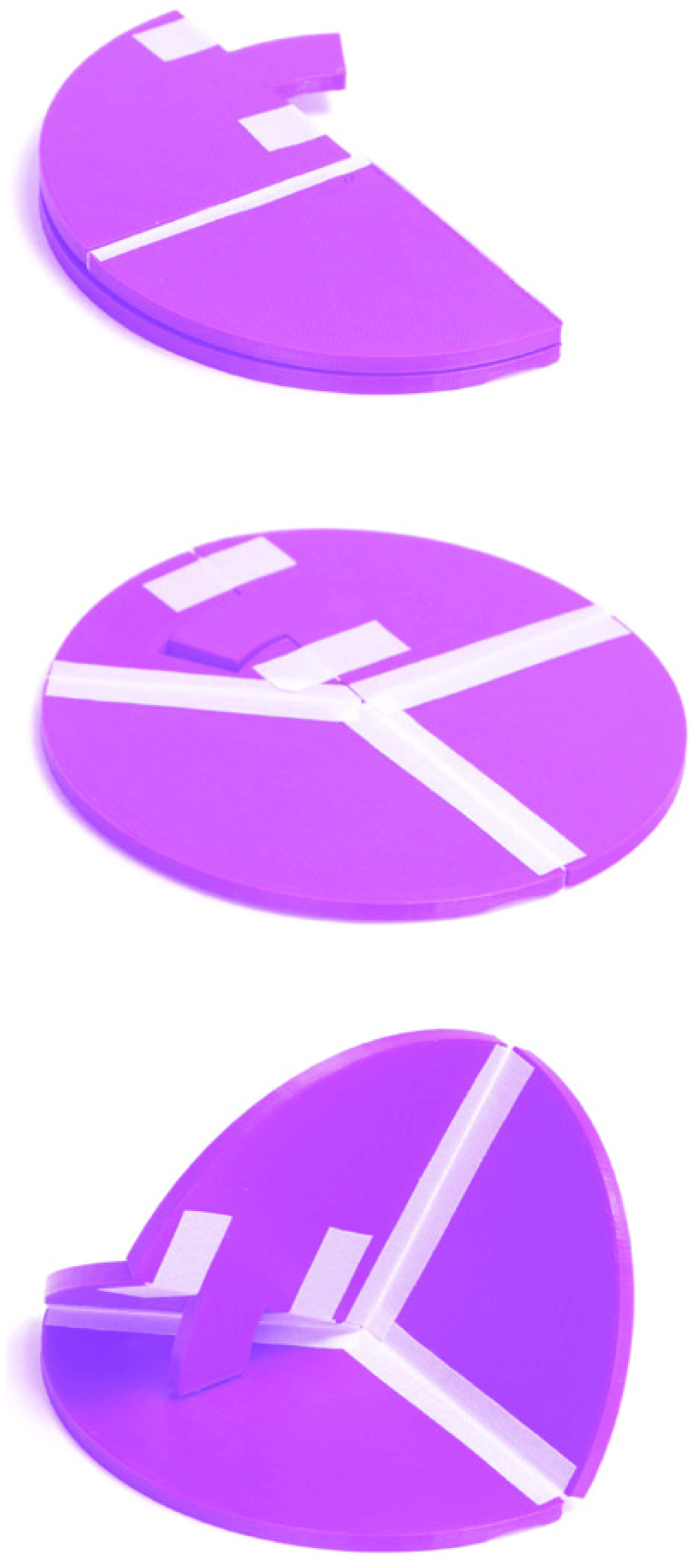
Figure 24Flat-foldable sector panel ThUDS with flat foldability in the same direction as deployment. Shown in flat-folded, flat, and deployed states.
4.2 Adaptation: slider sector panel ThUDS
Another adaptation of the sector panel ThUDS is replacing panel 2 with a sliding joint. This can be defined using Eq. (18) and the following:
where θ2 is the slider angle and θ12 is measured opposite θ1 rather than along θ1. Other parameters are the same as defined above. The slider angle tracks an angle of θ2 (such that ). An example of this is shown in Fig. 25 in various states, with a slider larger than θ2 to allow for constrained motion.
4.3 Adaptation: inverted motion
A sector panel ThUDS is designed from a flat, unfolded state to block motion before reaching a flat-foldable state. Motion can be inverted such that a sector panel ThUDS deploys from a nondevelopable, flat-foldable state instead of a flat, developable state. This is done by replacing Eqs. (18) through (20) with the following:
and replacing Eq. (27) with the parameters depicted in Fig. 26. Note that for this adaptation θ12 is also opposite θ1 instead of along θ1, as specified for the slider adaptation above.
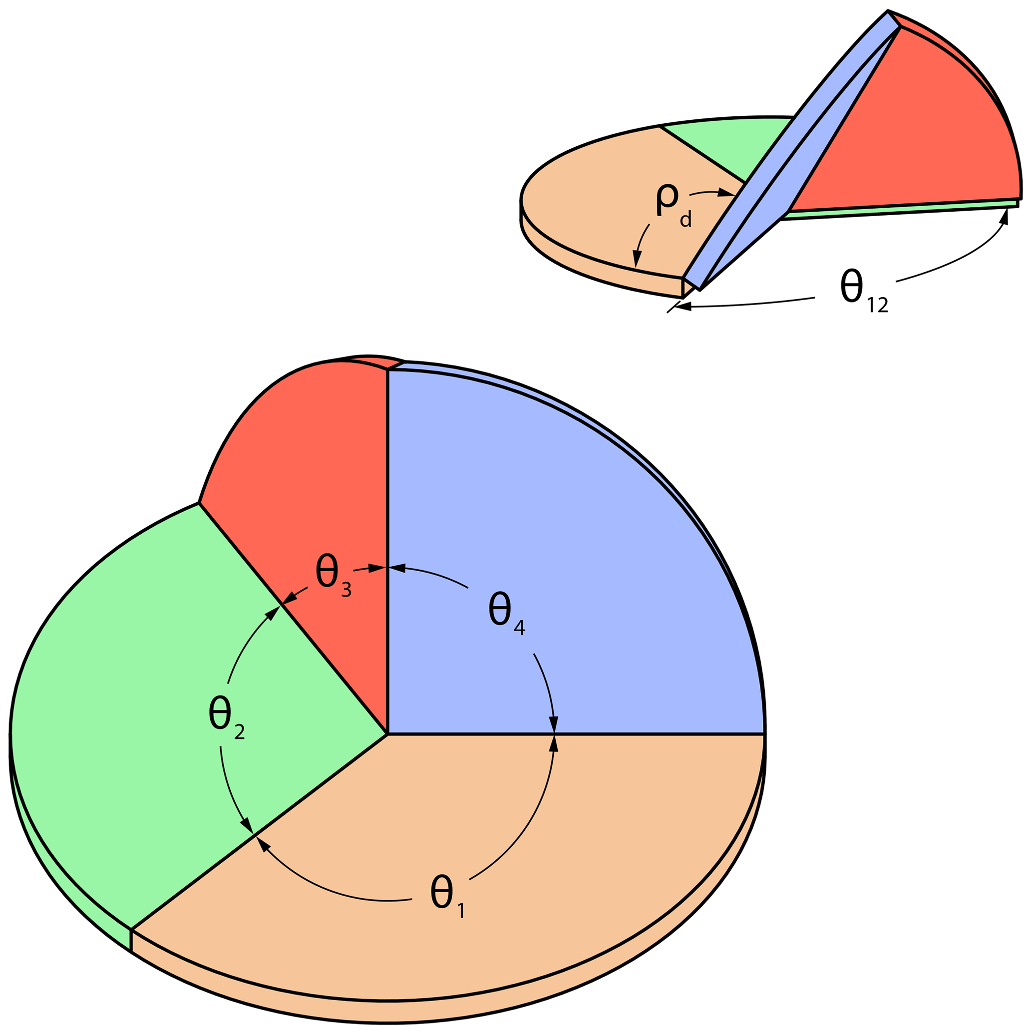
Figure 26General diagram for a sector panel ThUDS with inverted motion depicting key parameters.
Figure 27 is a physical example of this adaption. Each panel is shifted as needed, using the offset panel technique for thickness accommodation to allow for flat foldability (Lang et al., 2018).
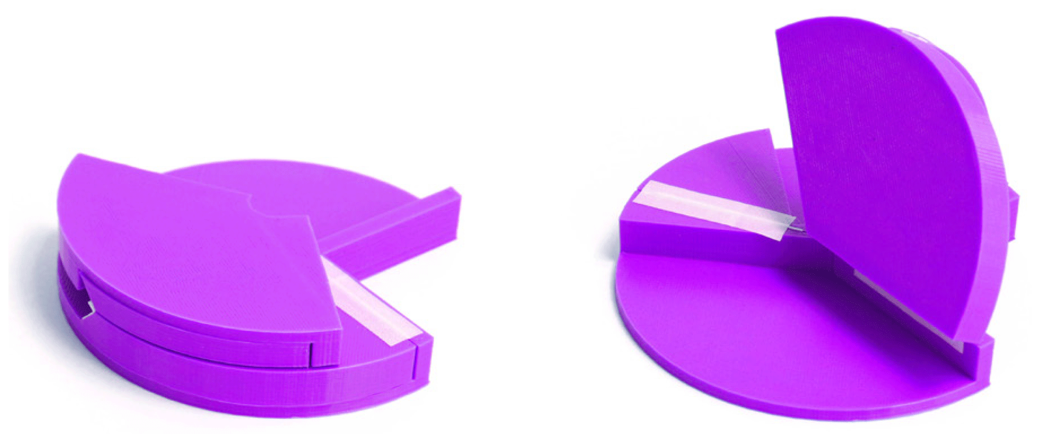
Figure 27Inverted sector panel ThUDS with thickness added and removed to allow for flat foldability. Shown in flat-folded and deployed states.
ThUDS were implemented in origami-based designs to demonstrate their benefit in products and systems. Several of these were selected and are shown with increasing levels of complexity.
5.1 Collapsible bookend
Bookends are often difficult to store due to their shape. By making them collapsible, they can be easily stored, while being able to maintain their function when deployed.
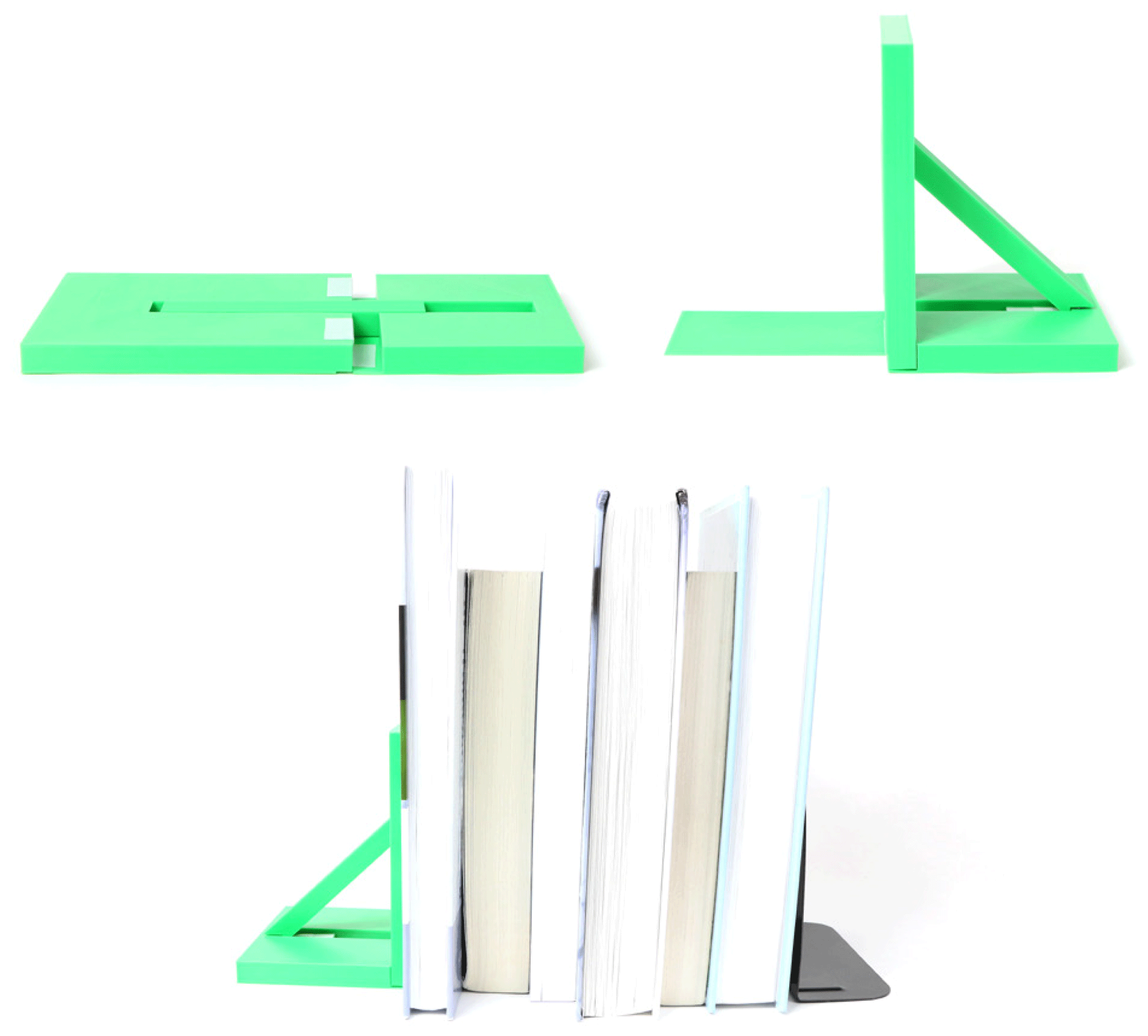
Figure 28Collapsible bookend with planar deploying strut ThUDS. Shown in flat state, deployed state, and in functional use.
By implementing a 90∘ planar deploying strut ThUDS, the collapsible bookend shown in Fig. 28 was developed, which closely resembles a typical metal bookend. The bookend has a flat state, such that it can be stored in a box or even on the bookshelf between books. Then, it can be quickly deployed for use and maintain stability with books resting against it. See Table A1 in Appendix A for parameter values.
Additionally, the thickness of the links is utilized by design to create surface contact, placing the strut link in compression when in use. This allows loads to be transmitted through the strut and ground links to the shelf, while still allowing for folding.
5.2 Desk mobile phone holder
An origami-based desk mobile phone holder, shown in Fig. 29, was designed using a sector panel ThUDS. It has a flat state for easy storage and can be deployed for holding a mobile phone. A dihedral angle of 60∘ was selected for simplicity but could be designed for other angles.
This design utilizes the material thickness in multiple ways. Tabs and corresponding slots were added to isolate loads from the joints. A ridge was also added to help lock panels 2 and 3 in place, further removing the load from the joints. Additionally, a groove was designed in panel 1 for panel 2 to sit in. Together, these features constrain the motion of the ThUDS and improve stability, while maintaining desired functionality and foldability.
5.3 Side table
Furniture is often cumbersome and bulky, thus being difficult to move and store. Folding allows for easier movement and reduces the required storage space. An origami-based foldable side table was created by replacing joints between the legs and table top with flat-foldable planar deploying strut ThUDS, as shown in Fig. 30. The equations in Sect. 3.1 were used to determine the ThUDS dimensions (see Table A1 in Appendix A).
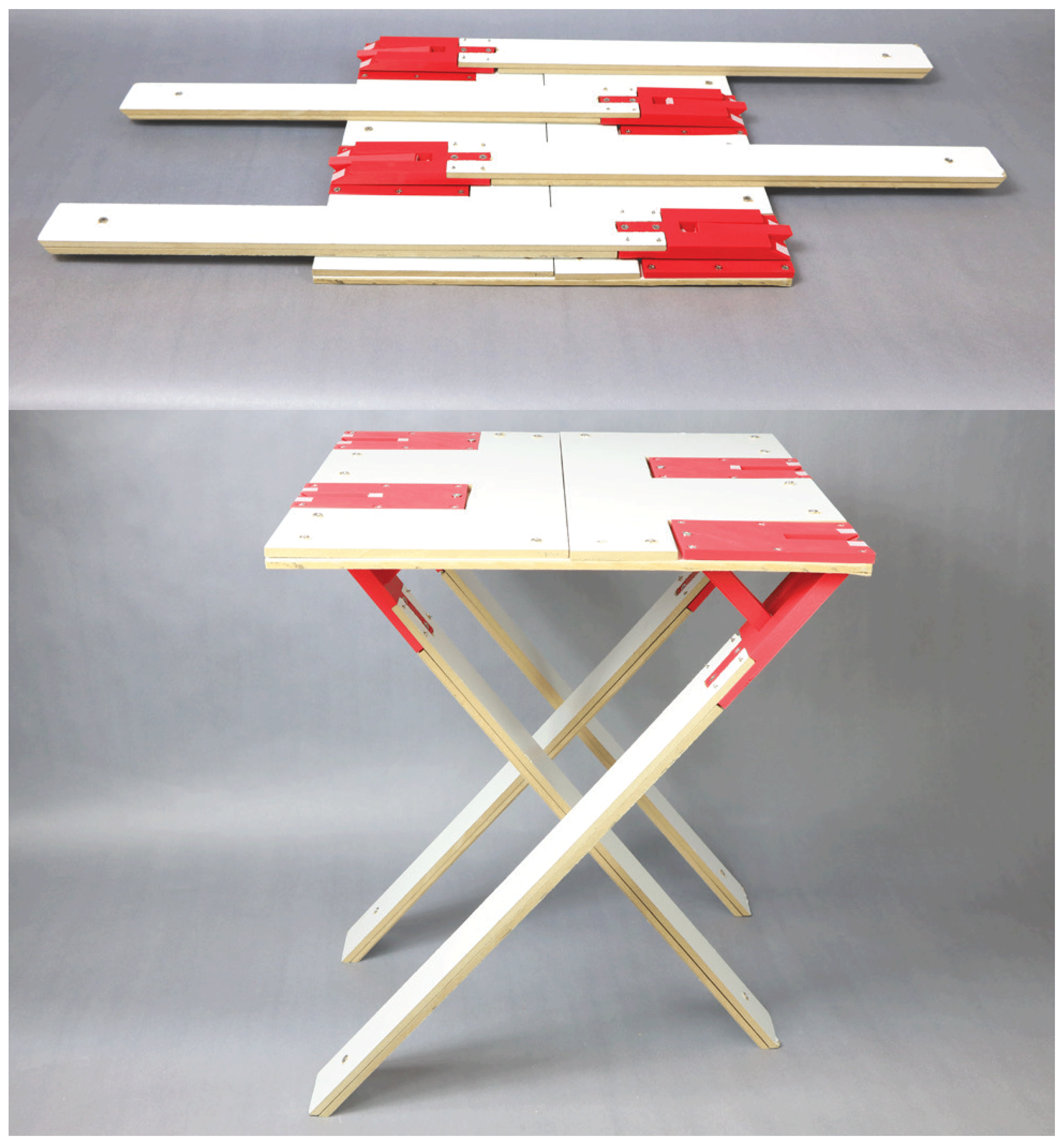
Figure 30Flat-foldable side table example. The planar deploying strut ThUDS used are similar to those shown in Fig. 10.
Because flat-foldable ThUDS were used, the side table is able to collapse to a completely flat position, as shown in Fig. 30. Thus, stowability is increased while functionality is maintained. Joints were offset to utilize the link thickness to create surface contact, helping to remove loads from the joints.
5.4 Flat-foldable unit cell
Square or rectangular structures are common in a variety of origami-based applications. With this in mind, a square unit cell was created that is able to be folded flat, then deployed, and locked in a square stable state. Figure 31 shows the unit cell in its flat, deployed, and locked states. This unit cell can be used as a building block for other applications.
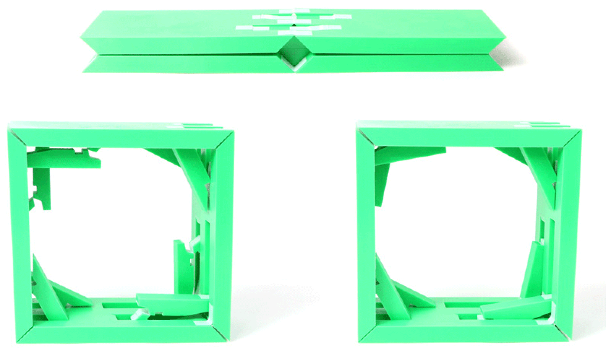
This design was created by placing a pair of planar deploying strut ThUDS in two opposing corners and a pair of inverted planar deploying strut ThUDS in the other two opposing corners. Each has a dihedral angle of 90∘. Locking is enabled through the motion-blocking capability of ThUDS and the bistable nature of inverted planar deploying strut ThUDS.
Additionally, this configuration transfers loads through a ThUDS, rather than a joint via the strut link, through link contact with the sides. This adds to the stability of the system and potential load-carrying capacity.
When selecting and designing a ThUDS configuration for a particular application, it is important to address the trade-offs tied to the type used and parameters chosen. The strategic utilization of material thickness to allow for surface contact and increased stability comes with increased complexity. On the other hand, the simpler the design, the less the material thickness can be utilized for functionality, such as reducing loading on the joints.
One key benefit of a ThUDS is the ability to adapt them to nearly any material, and thus, they can be used in a wide variety of applications. By assuming near-zero thickness, ThUDS simplify to transcrease hard stops and can be directly incorporated within an origami pattern (Andrews et al., 2019). When applied to thick materials, surface contact can be used for increased stability and load-bearing.
The examples herein show the possibility of using flexible joints, such as tape or fabric, when contact is exhibited between links. This is because loads are able to pass predominately through the links, reducing the stress on the joints. These examples also show that ThUDS can become degenerate in their flat states. Remedies for this include adding material beneath the joint plane (see Fig. 16) and residing on a thickened plane (see Figs. 25 and 27).
Furthermore, ThUDS can be embedded in any system built from a flat sheet, whether this is an origami pattern or a thick folding system. For example, the origami-based folding side table shown in Fig. 30 has 3D-printed polylactic acid (PLA) ThUDS embedded in a wooden structure.
Finally, ThUDS can be used in series, parallel, or a combination of both. The examples in Sect. 5.1 and 5.2 exhibit only a single ThUDS. The side table has four ThUDS in series (see Fig. 30), and the flat-foldable unit cell shown in Fig. 31 has a series of four pairs of parallel ThUDS.
This work has focused on methods for blocking motion and incorporating stability in origami-based systems through the development of thickness-utilizing deployable hard stops (ThUDS), which have both flat and deployed states. Methods used to design the ThUDS were presented using diagrams, equations, and examples. These were separated into two categories, namely deploying strut ThUDS and sector panel ThUDS. Special cases, such as obtaining flat foldability and adaptations, such as inverted motion, were presented for each.
Four origami-based examples were also shown, all of which have flat storage states and stable, functional deployed states. Through these examples, it has been shown that a ThUDS can be applied in functional ways to items with practical use. How a ThUDS utilizes thickness is also illustrated and discussed. Thickness-utilizing deployable hard stops maintain foldability and improve stability, while utilizing thickness, and are able to be completely contained within the thickness of a design.
Table A1Parameter values for planar deploying strut ThUDS examples. Lengths are in inches (millimeters). Parameters marked “–” are not part of the technique used to create that prototype. Whether flat foldability (FF) is possible is denoted in the last column.
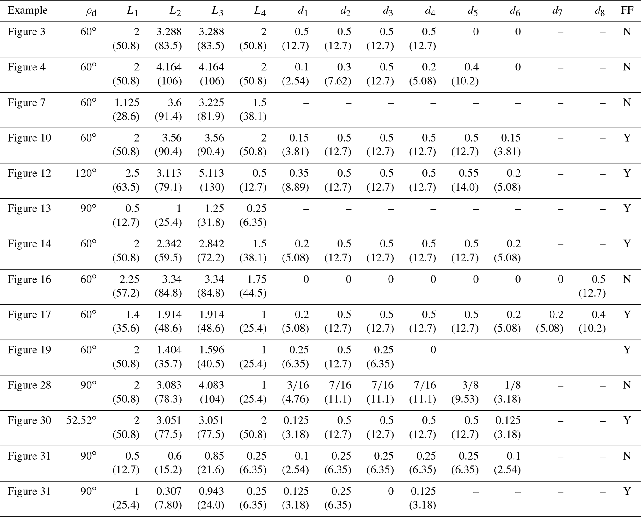
Table A2Parameter values for spherical deploying strut ThUDS examples. Lengths are in inches (millimeters). Parameters marked “–” are not part of the technique used to create that prototype. Whether flat foldability (FF) is possible is denoted in the last column.
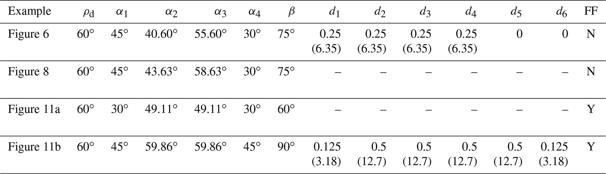
Table A3Parameter values for sector panel ThUDS examples. Parameters marked “–” are not part of the technique used to create that prototype. Whether flat foldability (FF) is possible is denoted in the last column.

All of the pertinent data are provided in the text of the publication.
DWA was the lead author and performed or directed the modeling and prototyping represented in the paper. SPM initially structured the paper, guided the direction of the research presented, and provided editorial input. LLH guided the direction of the research, made contributions on presentation approaches for the mechanisms, and provided reviews of the paper.
The authors declare that they have no conflict of interest.
The authors acknowledge the support of Bethany Parkinson, Brooklyn Clark, and Lais Oliveira in the fabrication of prototypes, and the National Science Foundation, through NSF (grant no. 1663345), and the Air Force Office of Scientific Research, through Florida International University (grant no. FA9550-19-1-0290).
This research has been supported by the National Science Foundation (grant no. 1663345) and the Air Force Office of Scientific Research (grant no. FA9550-19-1-0290).
This paper was edited by Guowu Wei and reviewed by Jason Ku and one anonymous referee.
Andrews, D. W., Avila, A., Butler, J., Magleby, S. P., and Howell, L. L.: Kirigami-based deployable transcrease hard stop models usable in origami patterns, in: Proceedings of the ASME Design Engineering Technical Conference, ASME, Anaheim, CA, USA, Vol. 5B-2019, 1–9, https://doi.org/10.1115/DETC2019-98056, 2019. a, b, c, d, e, f, g, h, i
Avila, A., Magleby, S. P., Lang, R. J., and Howell, L. L.: Origami fold states: concept and design tool, Mech. Sci., 10, 91–105, https://doi.org/10.5194/ms-10-91-2019, 2019. a
Banerjee, H., Pusalkar, N., and Ren, H.: Single-motor controlled tendon-driven peristaltic soft origami robot, J. Mech. Robot., 10, 8–12, https://doi.org/10.1115/1.4041200, 2018. a
Bernard, A., Aguiar, C. D., Green, K. E., and Member, S.: Model for a Rigid, 3D Mechanism Inspired by Pop-Up Origami, and its Application to a Re-configurable, Physical Environment, 2018 IEEE 14th International Conference on Automation Science and Engineering (CASE), 1146–1151, 2018. a
Bowen, L. A., Baxter, W. L., Magleby, S. P., and Howell, L. L.: A Position Analysis of Coupled Spherical Mechanisms Found in Action Origami, Mech. Mach. Theory, 77, 13–24, https://doi.org/10.1016/j.mechmachtheory.2014.02.006, 2014. a
Butler, J., Pehrson, N., and Magleby, S.: Folding of Thick Origami Through Regionally Sandwiched Compliant Sheets, J. Mech. Robot., 12, 1–9, https://doi.org/10.1115/1.4045248, 2020. a
Chen, Y., Peng, R., and You, Z.: Origami of thick panels, Science, 349, 396–400, https://doi.org/10.1126/science.aab2870, 2015. a, b
Cheung, K. C., Tachi, T., Calisch, S., and Miura, K.: Origami interleaved tube cellular materials, Smart Mater. Struct., 23, 094012, https://doi.org/10.1088/0964-1726/23/9/094012, 2014. a
Deng, D. and Chen, Y.: Origami-Based Self-Folding Structure Design and Fabrication Using Projection Based Stereolithography, J. Mech. Des.-T. ASME, 137, 1–12, https://doi.org/10.1115/1.4029066, 2015. a
Fang, H., Chu, S. C. A., Xia, Y., and Wang, K. W.: Programmable Self-Locking Origami Mechanical Metamaterials, Adv. Mater., 30, 1–9, https://doi.org/10.1002/adma.201706311, 2018. a
Filipov, E. T., Tachi, T., and Paulino, G. H.: Origami tubes assembled into stiff, yet reconfigurable structures and metamaterials, P. Natl. Acad. Sci. USA, 112, 12321–12326, https://doi.org/10.1073/pnas.1509465112, 2015. a
Filipov, E. T., Paulino, G. H., and Tachi, T.: Deployable Sandwich Surfaces with High Out-of-Plane Stiffness, J. Struct. Eng., 145, 1–15, https://doi.org/10.1061/(ASCE)ST.1943-541X.0002240, 2019. a
Foschi, R. and Tachi, T.: Designing Self-Blocking Systems With Non-Flat-Foldable Degree-4 Vertices, in: Origami 7: The proceedings from the 7th international Meeting on Origami in Science, Mathmatics, and Education, 795–809, Tarquin, Oxford, UK, 2018. a, b
Greenwood, J., Avila, A., Howell, L. L., and Magleby, S. P.: Conceptualizing Stable States in Origami-Based Devices Using an Energy Visualization Approach, J. Mech. Design, 142, 093302, https://doi.org/10.1115/1.4046437, 2020. a
Guérinot, A. E., Magleby, S. P., Howell, L. L., and Todd, R. H.: Compliant Joint Design Principles for High Compressive Load Situations, J. Mech. Design, 127, 774, https://doi.org/10.1115/1.1862677, 2005. a
Howell, L. L.: Compliant Mechanisms, John Wiley & Sons, New York, NY, USA, 2001. a
Jacobsen, J. O., Winder, B. G., Howell, L. L., and Magleby, S. P.: Lamina emergent mechanisms and their basic elements, J. Mech. Robot., 2, 1–9, https://doi.org/10.1115/1.4000523, 2010. a
Ku, J. S.: Folding Thick Materials Using Axially Varying Volume Trimming, in: Volume 5B: 41st Mechanisms and Robotics Conference, ASME, Cleveland, OH, USA, V05BT08A044, https://doi.org/10.1115/DETC2017-67577, 2017. a, b
Ku, J. S. and Demaine, E. D.: Folding flat crease patterns with thick materials, J. Mech. Robot., 8, 031003, https://doi.org/10.1115/1.4031954, 2016. a, b
Lang, R. J., Tolman, K. A., Crampton, E. B., Magleby, S. P., and Howell, L. L.: A Review of Thickness-Accommodation Techniques in Origami-Inspired Engineering, Appl. Mech. Rev., 70, 010805, https://doi.org/10.1115/1.4039314, 2018. a, b, c
Lang, R. J., Brown, N., Ignaut, B., Magleby, S., and Howell, L.: Rigidly Foldable Thick Origami Using Designed-Offset Linkages, J. Mech. Robot., 12, 1–13, https://doi.org/10.1115/1.4045940, 2020. a
Ma, J., Dai, H., Shi, M., Yuan, L., Chen, Y., and You, Z.: Quasi-static axial crushing of hexagonal origami crash boxes as energy absorption devices, Mech. Sci., 10, 133–143, https://doi.org/10.5194/ms-10-133-2019, 2019. a
McCarthy, J. M. and Soh, G. S.: Analysis of Spherical Linkages, in: Geometric Design of Linkages, 2nd Edn., Springer, New York, NY, USA, 155–178, https://doi.org/10.1007/978-1-4419-7892-9_7, 2011. a
Morgan, M. R., Lang, R. J., Magleby, S. P., and Howell, L. L.: Towards developing product applications of thick origami using the offset panel technique, Mech. Sci., 7, 69–77, https://doi.org/10.5194/ms-7-69-2016, 2016. a
Sadeghi, S., Betsill, B. D., and Li, S.: Design and optimization of an origami-inspired jumping mechanism with nonlinear stiffness properties, Proceedings of the ASME Design Engineering Technical Conference, 8, 1–8, https://doi.org/10.1115/DETC2019-97706, 2019. a
Su, H. J., Castro, C. E., Marras, A. E., and Zhou, L.: The Kinematic Principle for Designing Deoxyribose Nucleic Acid Origami Mechanisms: Challenges and Opportunities1, J. Mech. Des.-T. ASME, 139, 1–9, https://doi.org/10.1115/1.4036216, 2017. a
Tachi, T.: Rigid Foldable Thick Origami, in: Origami 5: Fifth International Meeting of Origami Science, Mathematics, and Education, CRC Press, Boca Raton, FL, USA, 2011. a
Yang, Y. and You, Z.: Geometry of transformable metamaterials inspired by modular origami, J. Mech. Robot., 10, 1–10, https://doi.org/10.1115/1.4038969, 2018. a
Yasuda, H., Chen, Z., and Yang, J.: Multitransformable leaf-out origami with bistable behavior, J. Mech. Robot., 8, 1–6, https://doi.org/10.1115/1.4031809, 2016. a
Yasuda, H., Gopalarethinam, B., Kunimine, T., Tachi, T., and Yang, J.: Origami-Based Cellular Structures with In Situ Transition between Collapsible and Load-Bearing Configurations, Adv. Eng. Mater., 21, 1–8, https://doi.org/10.1002/adem.201900562, 2019. a
Yellowhorse, A. and Howell, L. L.: Three Approaches for Managing Stiffness in Origami-inspired Mechanisms, in: Proceedings of the ASME 2018 International Design Engineering Technical Conferences and Computers and Information in Engineering Conference, Vol. 5B-2018, Quebec City, Quebec, Canada, https://doi.org/10.1115/DETC2018-85450, 2018. a
Zhang, H., Zhu, B., and Zhang, X.: Origami kaleidocycle-inspired symmetric multistable compliant mechanisms, J. Mech. Robot., 11, 1–9, https://doi.org/10.1115/1.4041586, 2019. a