the Creative Commons Attribution 4.0 License.
the Creative Commons Attribution 4.0 License.
 | 20 Oct 2020
A new hand rehabilitation system based on the cable-driven mechanism and dielectric elastomer actuator
Heba Amin
Samy F. M. Assal
Hiroyasu Iwata
The increasing number of patients with hand disabilities after strokes or peripheral nerve injuries necessitates the continuous development of rehabilitation system devices to accelerate muscle recovery and to help patients regain the motor functions of their hands. This paper introduces the design of a hand rehabilitation system for patients who have a solitary impairment of their hand extension. The system was designed to be portable, simple, and cheap. Using a system based on a cable-driven mechanism instead of traditional rigid links reduces the degrees of freedom of the finger to one. The dielectric elastomer actuator was designed and fabricated as a smart actuator for the system, which supports the low cost of the system. A kinematic analysis of the cable-driven mechanism has been done. Parameters of the actuator were optimized to reach the required output. In order to characterize the performance of the actuator, a uniaxial tension test, isotonic test, and isometric test have been implemented.
- Article
(1672 KB) - Full-text XML
- BibTeX
- EndNote


The hand is a vital, multifunctional organ for humans that plays an important role in physical activities and in the development of fine and gross motor skills. Any disease disrupting the hand function will lead to disability and, consequently, worsen the quality of human life. The need to develop hand rehabilitation strategies became a vital issue with an increase in the number of patients (and old people in particular) who suffer from impairments in their hand motor function after strokes and injuries. The strategies for hand rehabilitation depend on maintaining the muscles' ability and preventing their atrophy by doing repetitive hand exercises (Brewer et al., 2012). As traditional, human-assisted therapy is challenging and expensive, many hand rehabilitation devices or robot-assisted therapies were recently introduced and achieved excellent results by enhancing the motor function of the muscles. Those devices offer a new kind of physiotherapy; in this way, patients practice moving their muscles by following or withstanding the robot's force. Recently, there have been significant developments with the advances in robotic technology, such as the exoskeleton and bioengineering, that have become a significant addition to physiotherapy methods.
As a result of the variety of hand rehabilitation protocols, different robots have been designed to run alternative therapies. The rehabilitation clinics have different types of stationary hand rehabilitation devices which are set up in the clinics and have acquired good results, especially with the computer interface assistance that increases the patients' motivation (Dovat et al., 2008; Schabowsky et al., 2010). The availability of these devices is still insufficient for the majority of patients, due to the long time required for motor recovery training and the expensive fees for using the equipment. Also, these devices do not help them directly in their daily life activities.
Portable devices introduce an alternative to avoid some of these issues as the patients can train themselves at home. The bulky exoskeleton device is the most common type of portable assistive system which supplies highly accurate motion. It is a mechanism of rigid links fixed onto the palm side of the hand and controls the hand–finger motion (Ranman and Al-Jumaily, 2012; Iqbal et al., 2014; Agarwal et al., 2015; Jo and Bae, 2015, 2016; Allotta et al., 2017; Jo et al., 2019). Despite its excellent results, the bulky size and complicated structure present a burden for the patient and limit its workspace area. Also, the rigid structures of some of these devices are impeding the therapeutic potential of robotics by reducing their biomimetic qualities, and the motion in non-actuated directions, such as finger abduction, could include having rigid axes of rotation that become misaligned with the finger's anatomic axis during motion (Chu and Patterson, 2018).
In contrast, soft rehabilitation devices, which are simple and lightweight, solve this problem by using the natural exoskeleton of the hand and wearable gloves to control hand motion. These devices have been fabricated from easily deformable materials such as fluids, gels, and soft polymers that have better biomimetic qualities, due to their increased compliance and inconstancy, while complying with the contours of the human body. The lack of rigid components removes constraints on non-actuated degrees of freedom and reduces joint alignment issues, which could prevent joint damage. The main problem of this type of device is its actuation system, as most of them are actuated by the pneumatic system, which has a large complex volume and low accuracy (Polygerinos et al., 2013; Zhang et al., 2015; Low et al., 2015; Jo and Bae, 2016; Chu and Patterson, 2018). Recently, a soft glove for hand rehabilitation with a cable-driven mechanism was introduced (Yamaura et al., 2009). Another trial was made by (Park et al., 2016), who proposed a cable-driven structure of the hand exoskeleton system for virtual reality purposes. Cherian et al. (2018) introduced the Exo-Glove, the most popular one, which is suitable for the extension and flexion of the finger. However, tendon-driven systems have a major limitation in that they induce significant joint reaction forces. In and Cho (2013) indicated that, since the tendons are attached further away with a larger moment arm compared to the actual human tendons, these forces should not be a problem unless the spasticity of the patient's fingers is very high.
Several types of actuators are used in hand rehabilitation systems. The electric motors are the standard type due to their availability, reliability, and easy torque control with high precision, but the rigid structure may affect safety. Although the pneumatic actuator has fewer requirements for maintenance and might be stopped under a load without causing damages, the difficulty in controlling it and the air storage bulk size limits its use. Also, the hydraulic actuator has the same problem as the size of its parts; however, it may supply higher actuated torque and can be controlled with high precision, as reported by Yue et al. (2017). There are some trials for using smart actuators in hand rehabilitation systems to decrease the disadvantage of the previous actuators; for example, Tang et al. (2013) designed an exoskeleton system to assist hand rehabilitation exercises based on a shape memory alloy actuator. While it offered a light and straightforward structure, its temperature-dependent nature makes precise control difficult.
Using dielectric elastomer materials (DEMs) as a smart actuator for the system might be a remedy for the common defects of actuation methods. The dielectric elastomer material has the closest material properties for natural muscles, particularly in the stress and strain levels. As mentioned by Pelrine et al. (2002) and Madden (2008), its strain is between 10 % and 100 %, which is similar to or higher than in muscle. Also, the stress is 0.1–8 MPa. Work density in the muscle may reach 40 kJ m−3, compared to between 10 and 150 kJ m−3 in silicone and VHB-based elastomers, respectively. The continuous power output of dielectric elastomers also matches or exceeds that of our skeletal muscle, with human muscle producing about 50 W kg−1 compared to about 400 W kg−1 in the elastomers. In addition, it does not have a temperature-dependent response like the shape memory alloys so that it can work in different environments.
As the design of the hand rehabilitation robotics is different from the traditional design of robots because it involves humans, the safety and availability of the device are essential requirements for the rehabilitation system. This research aims to design a bio-mimic, soft hand rehabilitation system that must be portable, simple, and cheap. A cable-driven mechanism is proposed to work instead of the rigid links and be actuated by the dielectric elastomer actuator. This design mimics the natural procedure of finger motion as the cable-driven and the dielectric elastomer actuator (DEA) represent, instead, the natural tendon and muscle, respectively. While there are a variety of hand rehabilitation devices for the patients whose therapy needs are different to others, the target patients for this rehabilitation system are those who have a solitary impairment of their hand extension, as in peripheral radial nerve compression or injury. Nicholls and Furness (2019) indicated that most patients respond well to conservative therapy. They are considering relative rest from offending muscle activity, such as limiting repetitive pronation, supination, wrist flexion, and ulnar deviation. If symptoms are not resolved with the cessation of activity and rest, then splinting is considered.
The rest of the paper is organized as follows. The kinematic and dynamic analysis of the natural hand is given in Sect. 2. The proposed design of the cable system is presented in Sect. 3. The development and fabrication of the DEA are presented in Sect. 4, while Sect. 5 presents the performance characterization of the DEA. The conclusion and future work are presented in Sects. 6 and 7, respectively.
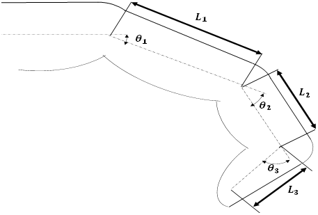
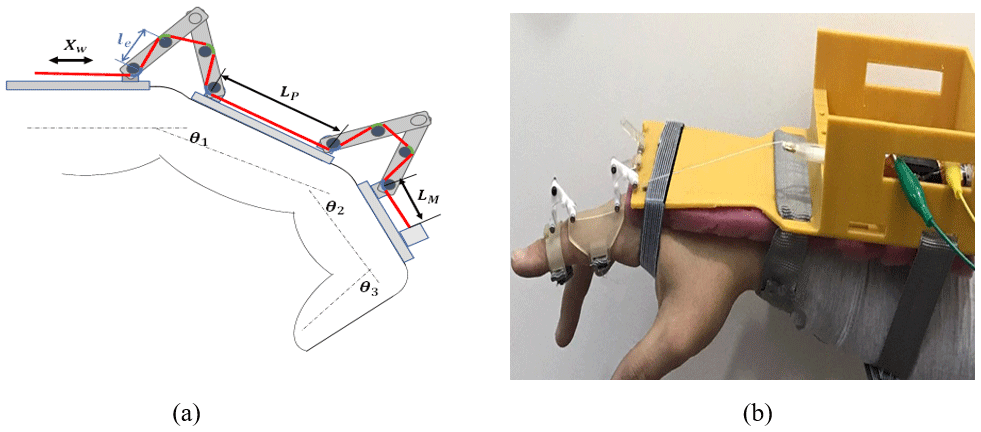
The natural hand is a complex combination of bones, muscles, and ligaments which determine the direction and range of motion. The natural hand has several kinds of motion such as flexion and extension and adduction and abduction for each finger and opposing movements between the thumb and other fingers, which present 27 DOF, as mentioned in Agur and Lee (1999). This large degree of freedom (DOF) makes the rehabilitation of all simultaneous motion challenging. For this research, we focus on the patients who have problems in their hand extension motion, so the other types of motion are being neglected, and each finger will be represented as a planar 3R mechanism. The patients will control their hand's flexion motion while the wiring systems will control the hand extension, as shown in Fig. 1. The fingertip pose Pi for each finger can be defined as a function of joint coordinates and described by the following equations:

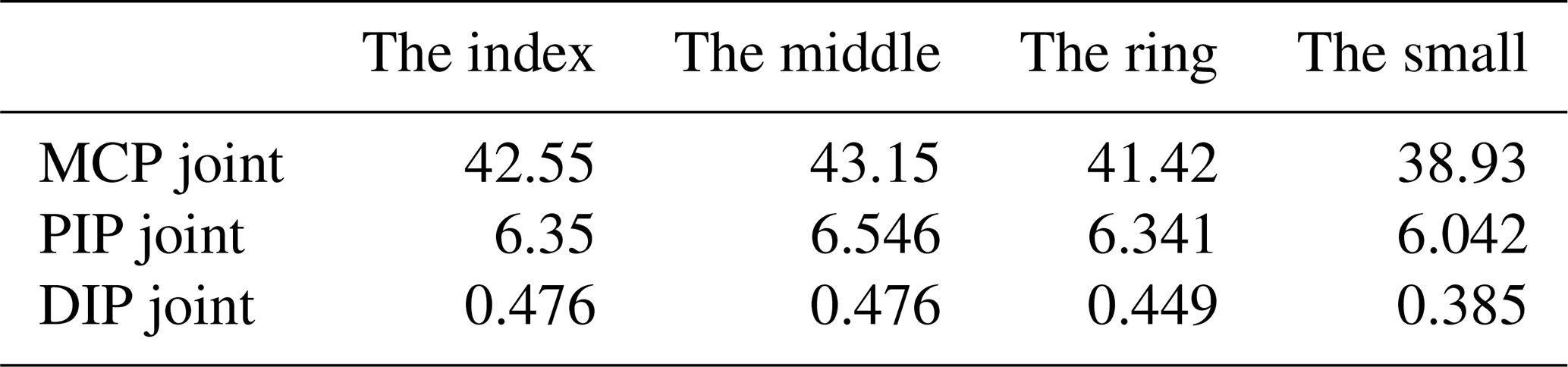
where i is the number of fingers () excluding the thumb, Px and Py are the position of fingertip position in x and y direction, , , are the proximal, middle, and distal phalanges lengths, respectively, and θ1, θ2, and θ3 are the angular displacement around the z axis for the three revolute joints. Table 1 shows the average dimension of the human hand finger which was reported by Serbest et al. (2018). According to the Lagrangian form, the equation of motion of each finger can be defined as follows:
where M(θ), , and g are the joint inertia matrix, the matrix of the centrifugal and Coriolis torques, and the gravity vector, respectively. τ is the required joint torque to move the finger, and it can be described as the difference between τa, the active joint torque (from active muscle or the external actuator), and τP, the passive resistance torque (from the natural elasticity and damping of human joints), as follows:
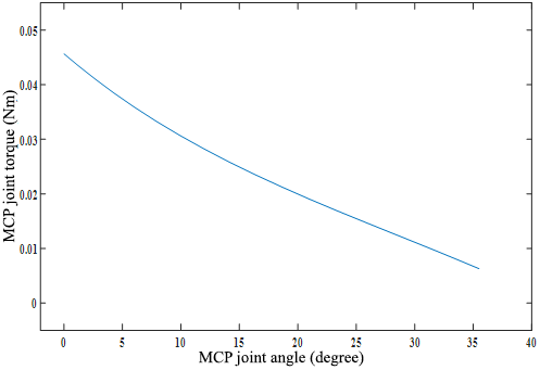
By using biomechanical models, as reported in Kuo and Deshpande (2012) and Agarwal et al. (2013), a passive joint torque for the various joints of the finger was calculated. To estimate the actuator's power requirements for the fingers' extension, a rigid dynamic model of the natural hand is developed by using ANSYS workbench software. In this model, rigid bodies to model the hand parts, such as the lower arm, the palm, and the phalanges, have been assumed. The links between the phalanges are described by rotational joints having fixed positions and fixed revolute axes. The thumb movements and both the abduction and adduction movements of the fingers are neglected. The wrist is fixed. The joint orientation was the input, and the joint torque τ was the output. The required joint torques from the actuator to extend the fingers joints from the relaxation state in (N mm) are presented in Table 2. Figure 2 shows the active metacarpal phalangeal (MCP) joint torque for the index finger to extend the finger from the relaxed position () to ().
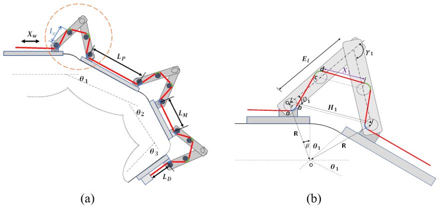
The proposed hand rehabilitation mechanism is physically connected to the natural hand exoskeleton, so it has a direct correspondence with the human joints and limbs. The device has been designed to exercise the extension motion for each finger, excluding the thumb. Using the cable-driven system instead of rigid links decreases the number of DOF from three to one as the linear motion of the cable wire moves the three revolute joints of the finger instantly. The system structure has been designed independently for each finger phalanx, as shown in Fig. 3a. A pair of small plastic links with pulleys are used to define a specific cable path around each finger joint. These links save the cable wire tension and prevent injuries due to the contact between the finger skin and the wire. These pairs of links are related to other fixed links built above the finger to support the system and are fabricated from Teflon to decrease the friction losses. To make the system more compact, the actuator will be on the hand's dorsal side. The kinematic model of the cable-driven system (CDS) was analysed to refer to the relationships between the cable lengths and the motion of the finger.
3.1 The kinematic model for the wiring system
Cable kinematics represent the relation between cable lengths and the fingertip end pose. The length of the force transmission cable should be calculated in terms of the angles of the finger joints. As shown in Fig. 3a, the linear displacement of the wire on one finger depends on the angular displacement of each joint as follows:
where Lw is the wire length, LP, LM, and le are constant values, and the values of , and X2 are functions of the finger joint. From Fig. 3b, we can calculate the values of the previous parameter as follows:
ρ1 is the length of the arc(ab) with blue colour,
ξ1 is the length of the arc(dc) with green colour,
where El, r, R1, and β1 are constant. By substituting with the same sequence for the other two pairs of links, we can find the values of ξ2, ξ3, ρ2, ρ3, X2, and X3 as functions of finger joint angles.
To decrease the power-transmitted losses due to the cable wire friction, the cable system has been modified depending on the robust correlation between the motion of a proximal interphalangeal joint (PIP) and distal interphalangeal joint (DIP), as reported by Rijpkema and Girard (1991) and Kamper et al. (2003). Jo et al. (2019) experimented to determine this correlation and indicated the following relation:
The modified system is shown in Fig. 4a, and the following equation can enable the maximum displacement of the wire for each finger:
by calculating the difference in the wire length in both cases of the full extension and full flexion of the finger. The maximum displacement of the wires is presented in Table 3.
Table 3The required cable length (in millimetres) for each finger.

3.2 The cable tension force calculation
Weir (2003) indicated that the natural hand could exert an average of 95.6 N forces at its fingertips during the power grasp motion. In this system, the desired exerted force is only for the extension motion of the fingers from the relaxed state, which needs much less than this value. The cable tension force at the end of the cable system wire Tw can be calculated by using inverse kinematics as follows:
where τ is the joint torque, and J is the Jacobian matrix of the cable wire, which represents the cable wire motion related to the finger joint motion as follows:
where , and
To avoid the redundancy of the mechanism, as the hand finger is a planar 3R mechanism, the cable tension force will be calculated from the following:
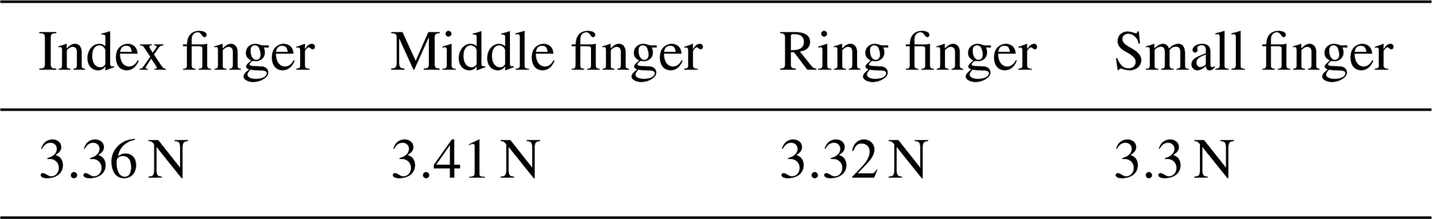
where J∗ is pseudo-inverse. Table 4 shows the required cable tension force to extend each finger from the relaxed state to a fully extended state. The friction force must be considered when we calculate the required tension force as the cable is routed through multiple segments. The friction transmission losses between the wire cable and the system parts model by the efficiency factor ξ is calculated as follows:
where μ is the coefficient of friction of the cable (μteflon=0.04), and σ is the bending angle along with the transmission. Table 5 represents the required cable tension force in each finger to make a full extension. The proposed prototype of a hand exoskeleton system was fabricated and assembled by using a 3D printer. Figure 4 shows the prototype for the index finger with the actuator that can be easily worn on the human hand.

To supply the required tension force for the cable-driven mechanism, a dielectric elastomer (DE) actuator has been designed and fabricated. The spring-rolled DE actuator is a linear actuator that extracts under the application of a high voltage and then returns to its original length after releasing the voltage. So, for this application, the actuator motion is inversely proportional to the hand finger motion, as the actuator will be activated for fingers' flexion and deactivated for fingers' extension.
A DE actuator is basically a compliant capacitor, where a soft, thin (µm) elastomer film is sandwiched between two compliant electrodes. When applying an electric voltage between the electrodes, plus charges on one electrode attract minus charges on the other. Then, electrostatic forces are the result and cause polymer stretching. The electrostatic pressure Pe depends on the applied voltage V and the thickness of the DE film t, according to the following relation:
where ε0 is the free space permittivity (8.85×10⁻¹² As Vm−1), and εr is the relative dielectric constant of the elastomer. However, the DEAs require a high voltage to work, and the supplied current is very low and with a magnitude in micro-amperes, so there is no fear of danger in using the high voltage as reported by Pourazadi et al. (2017).
Kofod (2008) indicated that the pre-strain of the DE material has a good impact on the actuator performance and enhances the breakdown strength. Due to the need to balance the pre-stretch of DE material and sustain the reaction force, Kovacs et al. (2008) proposed different methods to maintain the required pre-stretch. The spring roll actuator represents a common solution for this problem and achieves a large activation force with DE material. Since the force resulting from one layer of rolled DE material is not enough, several layers should be stacked together and warped around an elastic compressed spring core to increase the resulting force. The balance of the forces' reactions between the compressed spring and the pre-strained DE material is extremely vital in preventing the failure of the actuator.
4.1 Design of the DEA
Amin and Assal (2018) mentioned that the suitable design DEA consists of the main three steps. First, estimating the initial dimensions of the actuator that can produce the target output. Second, calculating the DE materials' pre-stretch force. Finally, selecting a suitable compression spring that can sustain this pre-stretch force.
4.1.1 Determine the initial dimension of the actuator
By using ANSYS Multiphysics Software, a numerical simulation for the DE actuator layers has been done to estimate the suitable dimensions of the actuator. There are several assumptions that might be taken into consideration while carrying out the electro-elastic analysis for the actuator. Mainly, the roll elastomer layers are cylindrical layers that shrink inside each other, the electrodes have no thickness and the electrode is equally distributed over all areas, except at the edges, and the electrodes are not adding any stiffness to the actuator. Several actuators with a different number of layers are being simulated under various loads. In the beginning, roll elastomers of one layer with different thicknesses and under the same activation voltage are analysed to determine the suitable thickness of the DE layer to enable the target axial displacement. The DEA with 76 µm thickness can obtain a 35 % axial strain under a 6.5 Kv activation load. With this thickness, the number of layers is gradually increased to achieve 4.5 N at 20 layers, with a 5 mm initial radius.
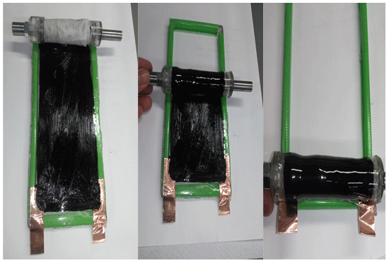
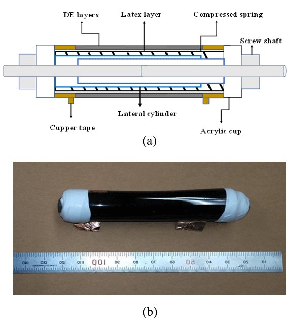
Figure 6(a) The schematic design of the spring roll DE actuator, and (b) the fabricated DE actuator.
4.1.2 Calculate the pre-stretch force of the DE material
By using Cauchy stress in the Cartesian coordinates, as reported by Kovacs et al. (2007), the stresses in the pre-stretch stage are analysed by assuming that the thickness of the pre-stretched film is very small compared to the radius of the coil spring core and the same previous assumptions. The wrapped elastomer film is treated as N cylindrical layers wound around a spring core. For , the Cauchy stresses in the deactivated stage could be calculated from the derivative of the strain energy potential W, considering the stretch ratio λ as follows:
where σr,n, σφ,n, and σz,n are stresses of layer n in radial, circumferential, and axial directions, respectively, and P is a hydrostatic pressure, given in Eq. (22) as follows:
According to the Yeoh form, the terms of strain energy W are related to the first invariant of the so-called left Cauchy–Green deformation tensor I, as follows:
where C10, C20, and C30 are the material parameters, and the first invariant I is given by the following:
The following recursive equation may show that the hydrostatic pressure on the layers increases based on the accumulated number of layers and the equilibrium condition for one layer.
where n is the layer number, and R is the radius of the layer, while t is the film thickness. In the activation stage, the electrostatic pressure Pe is added in the radial direction; so, it follows that:
Therefore, the Cauchy stresses in the activation stage can be given as follows:
From Eqs. (22) and (23), the hydrostatic pressure in the activation stage is given as follows:
A similar recursive equation of the hydrostatic pressure (Eq. 25) could be applied in this activation stage. By using the previous Eqs. (26)–(30), we can calculate the pre-stretch axial force in the material.
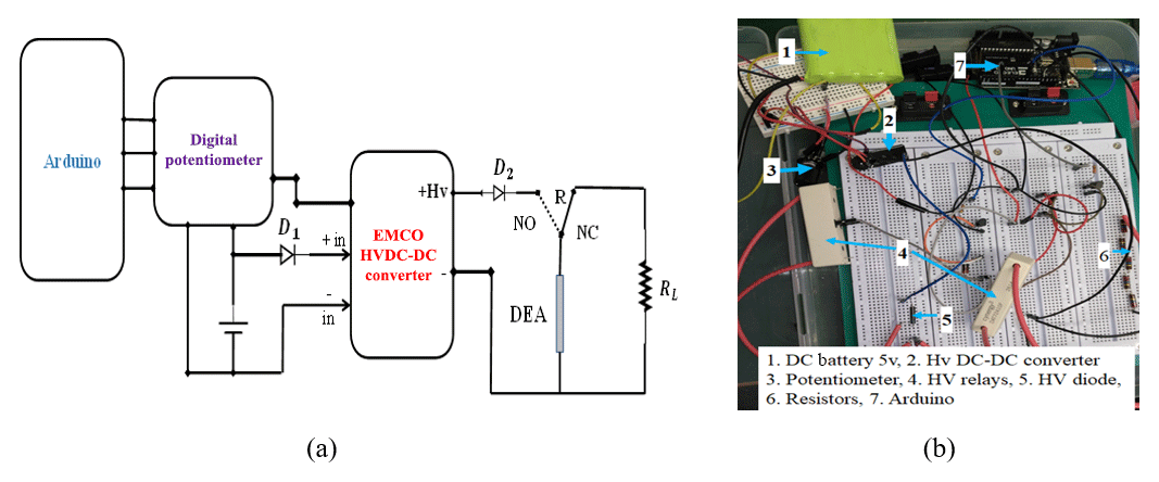
Figure 7The electric circuit of the DE actuator. (a) The schematic diagram. (b) A photo of the electric circuit.

Figure 8The DE actuator measurements. (a) The uniaxial tension test. (b) The isometric test.
4.1.3 Design spring core
Selecting a suitable compression spring is a very complicated step as the spring should not only sustain the pre-stretch force of the DE materials in the deactivation stage but also allow the actuator to extend freely in the activation stage. In the deactivation stage, the equilibrium force equation is as follows:
where Fd is the axial DE material force under the deactivation stage that equals to the pre-stretch force, k is the spring constant, and x1 is the initially compressed displacement of spring. The equilibrium equation in the activation stage is as follows:
where the Fa is the activation force, x and a are the axial displacement and acceleration, respectively, and x2 is the displacement under the fully activated voltage.
Table 6The constructional parameters of the spring roll DE actuator.

4.2 Fabrication of the DEA
The fabrication process of the spring roll dielectric elastomer actuator was done manually and consisted of three main processes:
-
Acrylic films of VHB 4910 (1 mm) are used since they are commercially available and offer a strong adhesiveness, which simplifies the manufacturing of actuators. As the pre-strain of DE materials is an essential step, due to enhancing the electric breakdown strength of the material, two layers of a commercial DEMs (3M VHB 4910 tape) were biaxially stretched and fixed on the acrylic frame until the the electrode layer was added.
-
A conductive carbon grease was introduced as the electrode material. It is characterized by low tensile stiffness and electrical conductivity, and it allows continuous contact with the adjacent film layers. The electrode layers are manually put on to both sides of one pre-stretch DE layer, as shown in Fig. 5. The copper conductive tape was used to connect the electricity to the two electrodes. After adding the electrode layers, the two pre-stretch layers are stacked together and fixed onto the frame.
-
By using plastic caps with a telescopic cylinder and screw hub, the spring core is compressed. A thin latex layer covers the spring outside surface to prevent contact with the electrode layer. Then wrapped manually around a compressed spring as shown in Fig. 5.
Figure 6 shows a schematic configuration and a fabricated prototype of the DE actuator. Table 6 lists the specifications of the required DEA for the hand rehabilitation system. As the actuator works under high-voltage activation, there are several points that must be taken into consideration. The EMCO high voltage (HV) DC–DC converter has been used to supply the high voltage. This converter is characterized by a lower output current (167 µA), which guarantees the safety of the user. It was controlled by using a digital potentiometer and Arduino software, as shown in Fig. 7. While the actuator is basically a capacitor, a dissipation circuit with 100 MΩ resistance and high-voltage relays (to avoid sparks) is used. A high-voltage diode was connected to the output of the HV DC converter to prevent current reversal.
In order to determine the actuator performance, uniaxial tension tests in the deactivated stage and isotonic and isometric tests in the activated stage have been carried out. The isotonic test gives the relative change in the actuator's length vs. the voltage under a constant load. The isometric test measures the resulting force vs. the voltage, while the actuator's length remains constant.
5.1 Measurement setup
During the uniaxial tensile force, the actuator is hung from a rigid support, and weights are attached at the lower end to keep the initial pre-stretch, as shown in Fig. 8a. The weight load gradually increased by steps equal to 50 g, and the displacement was measured by using a digital Vernier caliper with a 0.01 mm resolution. In this way, the actuator does not move until the axial load equals the pre-stretch force of the material. For this research, the compressed spring must sustain the pre-stretch force so that the actuator moves under applied loads.
With the same technique, the axial displacement due to the activation voltage in the isotonic test has been measured by applying voltage incrementally. An isometric test was done to measure the resulting axial force of the actuator under an activation voltage with blocked strain. The actuator was fixed axially, and the axial force was measured by increasing the applied voltage by using force sensors attached to one end of the actuator, as shown in Fig. 8b. The actuator was blocked in its deactivated length by applying a linear increased DC voltage from 0 to 6.5 Kv, and the compression blocked force was measured.
5.2 Measurement results and discussion
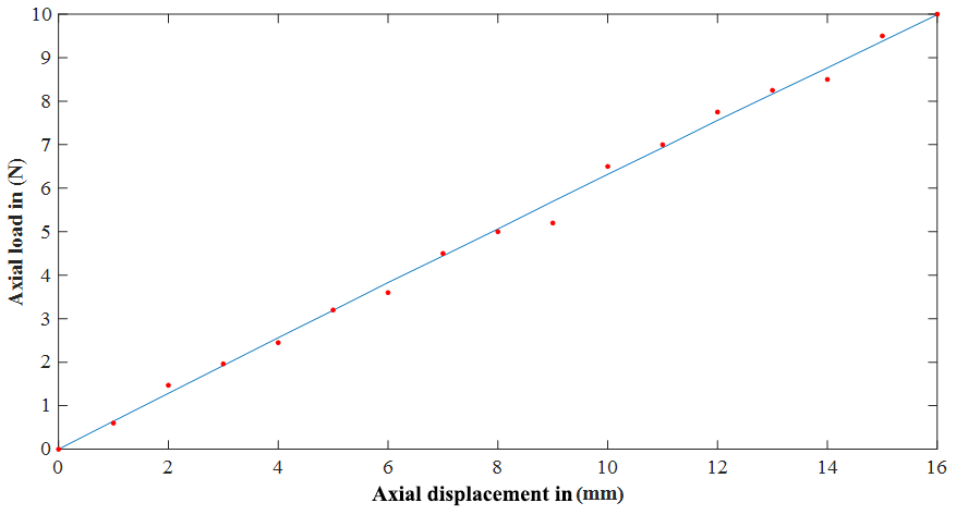
Several spring roll DE actuators in different groups were fabricated and tested. The relation between the applied force and displacement seemed to be a quasi-linear relation, as shown in Fig. 9. For the uniaxial test, the displacement increased linearly to achieve 2 cm at 12.5 N. The stiffness of the actuator equalled 610 N m−1.
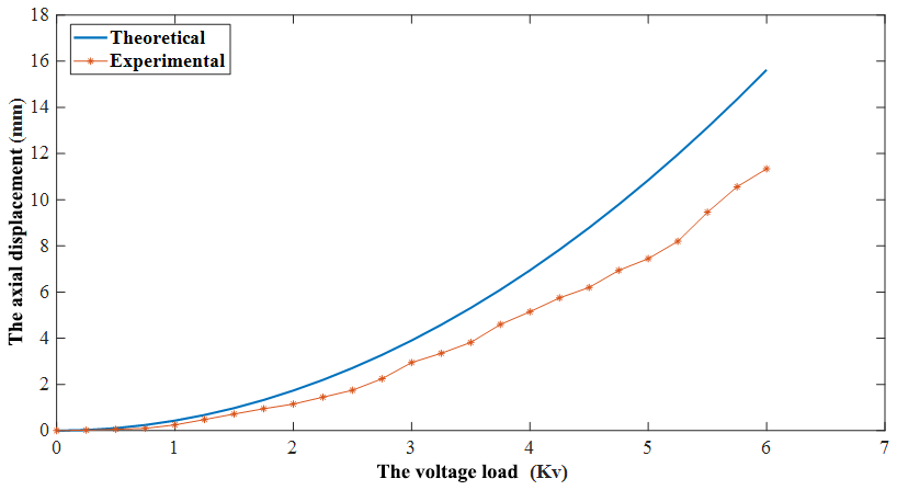
When applied to the high voltage in the DEA, the axial displacement increases gradually with the voltage. The actuator raises to its maximum displacement, equal to 11.3 mm, when 6.5 Kv voltage is applied. As shown in Fig. 10, the experimental and numerical results are approximately the same.
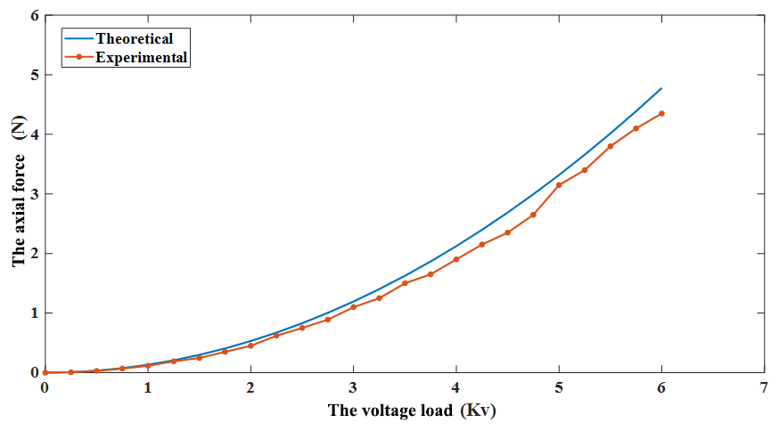
Figure 11 shows that the actuator achieved its maximum compressive blocking force of 4.35 N at its passive equilibrium length of 9 cm. When the displacement reached a displacement of 11.3 mm, this blocking force decreased to 0 N. This displacement of 11.3 mm represented the maximum displacement of the actuator.
While the DEA achieved the target requirement output, some points must be taken into consideration. First, it is highly recommended that one uses a fully automated fabrication process to limit damage during the fabrication process. Also, using dielectric elastomer material, which is prepared and fabricated for actuator purposes, will provide a positive result and decrease the probability of material damage.
The design of a soft hand rehabilitation system, based on a cable-driven mechanism, to exercise the fingers' extension movements was proposed. A kinematic and dynamic analysis of the human hand was obtained to determine the required torque to extend the fingers. The cable-driven design was analysed, and a prototype of the system was fabricated and assembled. The dielectric elastomer actuator was introduced as a smart actuator for the system. Theoretical analysis of the actuator was done to choose its suitable parameter. Several DE actuators were fabricated manually. Uniaxial, isotonic, and isometric tests for DE actuator were done to characterize the actuator's performance. A spring roll dielectric elastomer actuator with maximum axial displacement (11.3 mm) and maximum axial force (4.35 N) was produced. The number of the required DE actuators for the hand rehabilitation system is four, as each actuator can only move one finger.
Future work will focus on evaluating the performance of the cable-driven system on several patients. The evaluation will include its efficacy, safety, and comfort.
The data in this study can be requested from the corresponding author.
HA did all of the work for this research under the supervision of SFMA and HI.
The authors declare that they have no conflict of interest.
This paper was edited by Chin-Hsing Kuo and reviewed by two anonymous referees.
Agarwal, P., Hechanova, A., and Deshpande, A.: Kinamatics and dynamics of a biologically inspired index finger exoskeleton, ASME 2013 Dynamic Systems and Control Conference, California, USA, 21–23 October 2013, 3893, 2013.
Agarwal, P., Fox, J., Yun, Y., O'Malley, M. K., and Deshpande, A. D.: An index finger exoskeleton with series elastic actuation for rehabilitation: Design, control and performance characterization, Int. J. Robot. Res., 34, 1747–1772, 2015. a
Agur, A. M. R. and Lee, M. J.: Grant's Atlas of Anatomy, 10th edn., Lippincott Williams and Wilkins, Baltimore, chap. 2, 180–186, 1999.
Allotta, B., Conti, R., Meli, E., and Ridolfi, A.: Development, design and validation of an assistive device for hand disabilities based on an innovative mechanism, Robotica, 35, 892–906, https://doi.org/10.1017/S0263574715000879, 2017. a
Amin, H. and Assal, S. F.: Design Methodology of a Spring Roll Dielectric Elastomer-Based Actuator for a Hand Rehabilitation System, IEEE International Conference on Mechatronics and Automation (ICMA), Changchun, August 2018, 997–1002, 2018.
Brewer, L., Horgan, F., Hickey, A., and Wiliams, D.: Stroke rehabilitation: recent advances and future therapies: QJM-Int. J. Med., 106, 11–25, https://doi.org/10.1093/qjmed/hcs174, 2012. a
Cherian, B., Dominic, C., Vysakh, G., and Vishakh, K. R.: Exo-Glove: A Soft Wearable Robotic Hand for Stroke Survivors, Int. Res. J. Eng. Tech., 5, 3358–3364, 2018.
Chu, C.-Y. and Patterson, R. M.: Soft robotic devices for hand rehabilitation and assistance: a narrative review, J. Neuroeng. Rehabil., 15, 1–14, https://doi.org/10.1186/s12984-018-0350-6, 2018. a, b
Dovat, L., Lambercy, O., Gassert, R., Maeder, T., Milner, T., and Leong, C. T.: HandCARE: A cable-Actuated Rehabilitation System to train hand function after stroke, IEEE T. Neur. Sys. Reh., 16, 582–591, https://doi.org/10.1109/TNSRE.2008.2010347, 2008. a
In, H. and Cho, K. J.: Analysis of the Forces on the Finger Joints by a Joint-Less Wearable Robotic Hand, SNU Exo-Glove, in: Converging Clinical and Engineering Research on Neurorehabilitation, Biosystems and Biorobotics, vol 1, edited by: Pons, J., Torricelli, D., and Pajaro, M., Springer, Berlin, Heidelberg, 93–97, https://doi.org/10.1007/978-3-642-34546-3_15, 2013.
Iqbal, J., Khan, H., and Tsagarakis, N. G.: A novel exoskeleton robotic system for hand rehabilitation-Conceptualization to prototyping, Biocybern. Biomed. Eng., 1, 79–89, https://doi.org/10.1016/j.bbe.2014.01.003, 2014. a
Jo, I. and Bae, J.: Design and control of a wearable hand exoskeleton with force-controllable and compact actuator modules, IEEE International Conference In Robotics and Automation (ICRA), May 2015, 5596–5601, 2015. a
Jo, I. and Bae, J.: Design and control of wearable and force-controllable hand exoskeleton system, Mechatronics, 41, 90–101, https://doi.org/10.1016/j.mechatronics.2016.12.001, 2016. a, b
Jo, I., Park, Y., Lee, J., and Bae, J.: A portable and spring-guided hand exoskeleton for exercising flexion/extension of the fingers, Mech. Mach. Theory, 135, 176–191, https://doi.org/10.1016/j.mechmachtheory.2019.02.004, 2019. a
Kamper, D. G., Cruz, E. G., and Siegel, M. P.: Stereotypical fingertip trajectories during grasp, J. Neurophysiol, 90, 3702–3710, https://doi.org/10.1152/jn.00546.2003, 2003.
Kofod, G.: The Static Actuator of Dielectric Elastomer Actuators: How does pre-stretch improve actuation, J. Phys. D Appl. Phys., 41, 21, https://doi.org/10.1088/0022-3727/41/21/215405, 2008.
Kovacs, G., Lochmatter, P., and Wissler, M.: An Arm Wrestling Robot Driven by Dielectric Elastomer Actuators, Smart Mater. Struct., 16, 306–317, https://doi.org/10.1088/0964-1726/16/2/S16, 2007.
Kuo, P. H. and Deshpande, A.: Muscle-Tendon Units Provide Limited Contributions to the Passive Stiffness of the Index Finger Metacarpophalangeal Joint, J. Biomech., 45, 2531–2538, 2012.
Low, J.-H., Ang, M. H. Jr., and Yeow, C.-H.: Customizable Soft Pnumatic Finger Actuators for Hand Orthotic and Prosthetic Application, IEEE International Conference on Rehabilitation Robotics, Singapore, 11–14 August 2015, 380–385, 2015. a
Madden, J. D. W.: Dielectric Elastomers as High performance electroactive polymer: Dielectric Elastomers as Electromechanical Transedures, 1st edn., edited by: Carpi, F., de Rossi, D., Kornbluh, R. Pelrine, R., and Sommer-Larsen, P., Elsivier, 7–22, 2008.
Nicholls, K. and Furness, N. D.: Peripheral nerve compression syndromes of the upper limb, Surgery, 37, 288–293, https://doi.org/10.1016/j.mpsur.2019.02.011, 2019.
Park, Y., Jo, I., and Bae, J.: Development of a Dual-Cable Hand Exoskeleton System for vartual reality, IEEE/RSJ International Conference on Intelligent Robots and Systems, Daejeon, Korea, 9–14 October 2016, 2016. a
Pelrine, R., Kornbluh, R., Pei, Q., Stanford, S., Oh, S., Eckerle, J., and Meijer, K.: Dielectric Elastomer Artificial Muscle Actuators: Toward Biomimetic Motion, Smart Mater. Struct., 4695, 126–137, 2002.
Polygerinos, P., Lyne, S., Wang, Z., Nicolini, L. F., Mosadegh. B., Whitesides, G. M., and Walsh, C. J.: Towards a Soft Pneumatic Glove for Hand Rehabilitation, IEEE/RSJ International Conference on Intelligent Robotics, Tokyo, Japan, 3–7 November 2013, 1512–1517, 2013. a
Pourazadi, S., Shagerdmootaab, A., Chan, H., Moallem, M., and Menon, C.: On the electrical safety of dielectric elastomer actuators in proximity to the human body, Smart Mater. Struct., 26, 115007, https://doi.org/10.1088/1361-665X/aa89b1, 2017.
Ranman, Md. A. and Al-Jumaily, A.: Design and development of a hand exoskeleton for rehabilitation following stroke, Procedia Engineer., 41, 1028–1034, https://doi.org/10.1016/j.proeng.2012.07.279, 2012. a
Rijpkema, H. and Girard, M.: Computer Animation of Knowledge-Based Human Grasping: Computer graphics and interactive techniques, ACM SIGGRAPH Computer Graphics, New York, USA, 339–347, 1991.
Schabowsky, C. N., Godfrey, S. B., Holley, R. J., and Lum, P. S.: Development and pilot testing of HEXORR: hand EXOskeleton, J. Neuroeng. Rehabil., 7, 36, https://doi.org/10.1186/1743-0003-7-36, 2010. a
Serbest, K., Cilli, M., and Eldogan, O.: A Dynamic Virtual Hand Model For Estimating Joint Torques During The Wrist and Finger Movement, J. Eng. Sci. Technol., 13, 1665–1676, 2018.
Tang, T., Zhang, D., Xie, T., and Zhu, X.: An exoskeleton system for hand rehabilitation driven by shape memory alloy, IEEE International Conference on Robotics and biomimetics, Shenzhen, China, 12–14 December 2013, 756–761, 2013.
Weir, R. F.: Design of Artificial Arms and Hands for Prosthetic Applications: Standard Handbook of Biomedical Engineering and Design, Myer Kutz, McGraw-Hill, New York, 2003.
Yamaura, H., Matsushita, K., Kato, R., and Yokoi, H. Y.: Development of Hand Rehabilitation System Using Wire-Driven Link Mechanism for Paralysis Patients, International Conference on Robotics and Biomimetics, Guilin, China, 19–23 December 2009, 2009. a
Yue, Z., Zhang, X., and Wang, J.: Hand Rehabilitation Robotics on Poststroke Motor Recovery, Behav. Neurol., 2017, 3908135, https://doi.org/10.1155/2017/3908135, 2017.
Zhang, J., Wang, H., Tang, J., Guo, H., and Hong, J.: Modeling and Design of A Soft Pnumatic Finger for Hand, International Conference of Information and Automation, Lijiang, China, 8–10 August 2015, 2460–2465, 2015. a