the Creative Commons Attribution 4.0 License.
the Creative Commons Attribution 4.0 License.
 | 07 Feb 2020
On the analysis and design of a fully compliant large stroke slider-crank (rocker) mechanism
Çağıl Merve Tanık
Yiğit Yazıcıoğlu
Volkan Parlaktaş
In the literature, authors have made contributions in the area of partially compliant slider-crank (rocker) mechanisms possessing rigid joints that may cause backlash inherently. On contrary, fully compliant mechanisms offer no backlash which is a valuable property for the cases where high precision is required. In this paper, we proposed a fully compliant slider-crank mechanism that performs large stroke. Kinematic performance of the mechanism is investigated analytically. Dimensions of the mechanism are optimized to obtain maximum translational output, while keeping deflections of flexible hinges equal to each other and as small as possible. A design table displaying stroke, axis drift of the output segment, and critical stresses of compliant segments are presented. As an example, a compliant mechanism is designed by using rigid body replacement technique. Then, via nonlinear finite element analysis technique, analytical results are verified. Finally, a prototype is built to compare output stroke and axis drift with analytical approaches. The results of experiments verified that the theoretical approaches are consistent.
- Article
(1530 KB) - Full-text XML
- BibTeX
- EndNote


Compliant mechanisms are flexible mechanisms that transfer some or all of their motion through deformation of elastic segments. They are divided into two main categories; partially or fully compliant mechanism. Partially compliant mechanisms have at least one traditional (rigid) joint that may cause backlash inherently. By definition, a fully compliant mechanism does not possess a conventional rigid joint. Thus, fully compliant mechanisms obtain all their motion from deflection of compliant segments (Howell, 2001). This property is advantageous for the cases where precision is crucial. Compliant mechanisms have further advantages such as low cost, reduced number of parts, no need for lubrication, less wear and noise. Additionally, stored elastic energy due to deformation of compliant members brings mechanism to its original position. Pseudo-rigid-body model (PRBM) is used to simplify analysis of systems that undergo large, nonlinear deflections (Howell and Midha, 1996). Yu et al. (2016) proposed a new three degree-of-freedom (DOF) model based on PRBM for large deflection beams. In Liu and Yan's (2017) study modified pseudo-rigid- body modelling approach for compliant mechanisms with fixed guided beam flexurals was examined.
Rigid joints allow specific DOF between connected parts. However, rigid joints suffer from backlash and wear because of clearance between mating parts. Trease et al. (2005) proposed a revolute and translational compliant joint. Another novel three dimensional compliant translational joint with large stiffness ratio and small axis drift was presented (Yang et al., 2016).
Four link mechanisms (e.g. four-bar and slider-crank) have significant importance in the industry. Slider-crank mechanisms have numerous applications especially when kinematic inversions are considered. Researches on compliant slider-crank (rocker) mechanisms are limited in the literature. Hao et al. (2018) proposed a multi-mode compliant gripper. There is a fully compliant slider-crank mechanism available in their gripper. In Parlaktaş and Tanık's (2014) study the “single piece” compliant spatial slider-crank mechanism was introduced. In this study, deflections of the multiple axis flexural hinges were determined separately as bending and twist. Erkaya et al. (2016) investigated dynamics of the partially compliant slider-crank mechanism. In Alqasimi et al.'s (2016) study, a new model for a bistable compliant mechanism that is based on crank-slider mechanism was presented. In this study the slider is rigid thus the mechanism is partially compliant. In Pardeshi et al.'s (2017) study, monolithic compliant slider-crank mechanism with a rigid slider for motion amplification was proposed. Dao and Huang (2014) proposed an optimal design of a partially compliant slider-crank mechanism with circular cross-section flexure hinges.
Furthermore, there are some studies based on compliant linear-motion mechanisms which can not be categorized as slider-crank mechanism: Pavlović and Pavlović (2009) introduced compliant parallel-guiding mechanism's design procedure. A new compliant mechanism which is capable to realize axial translation of the link was presented. An inherent parasitic motion of the compliant parallel four-bar mechanism was compensated by exploiting center shift of a generalized cross-spring pivot in Hongzhe et al.'s (2012) study. Zhao, et al. (2017) designed a stiffness-adjustable compliant linear-motion mechanism.
Partially compliant mechanisms possess rigid prismatic joints (slider) in their structure. Prismatic joints inherently have disadvantages due to backlash and friction problems. An approach for optimum link proportions of the rigid body equivalent is proposed. The optimization objective is to maximize the translational motion of the slider equivalent while minimizing the relative link rotations. Minimization of link rotations is essential to keep maximum stresses in an acceptable range. Input–output motion relationships of the mechanism are determined. Resultant stresses at flexural hinges are obtained analytically. A design table is prepared for generalization of the dimensions that will be beneficial for other researchers. As a design example, an optimum mechanism is analyzed via finite element analysis (FEA) method and analytical results are verified. A prototype is manufactured and experiments are conducted. Also, it is ensured that the results of experiments are consistent with the theoretical approaches.
Note that, for the cases where crank of a slider-crank mechanism does not fully rotate, the mechanism may be called as slider-rocker mechanism. However, this makes an ambiguity for the identity of the mechanism. In this study, we prefer to name the mechanism as slider-crank disregarding the link proportions.
In Fig. 1a, a partially compliant slider-crank mechanism that possesses a prismatic joint between the slider and ground is presented. In our design, we replaced the prismatic joint by two identical and parallel compliant segments and a rigid segment as shown in Fig. 1b. By this way, if properly designed, translational motion for the output which acts as a slider can be achieved. Alternatively, compliant version of Roberts or Watt (Shigley and Uicker, 1980) type four bar mechanisms can be implemented for slider replacement. Specific points on coupler link of these mechanisms trace approximate straight lines. However, their coupler link performs rotation as well as translation. In our case, the output link performs no rotation but only translation (curvilinear translation). In the literature, paired double parallelogram mechanisms are used as sliders (Trease et al., 2005; Li et al., 2018). The advantage of this structure is straight line motion with no rotation. However, there is a big major disadvantage; if PRBM of this type is constructed, it can be calculated that DOF < 0. This case yields a locking mechanism. However, compliant version of this mechanism moves with axial deformation of compliant segments as well as bending. This property increases the stresses, therefore decreases stroke of the mechanism dramatically. Our major concern in this study is to increase the stroke as high as possible while keeping the stresses in an acceptable range.
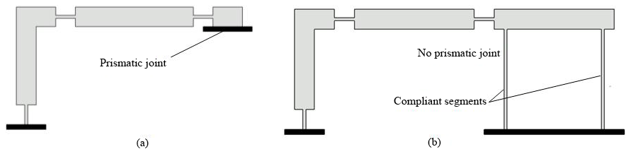
Figure 1(a) Partially compliant slider-crank with prismatic joint and (b) proposed fully compliant slider-crank.
In Fig. 2a, PRBM of the fully compliant slider-crank mechanism is displayed. This PRBM is essentially a six-link mechanism, where two of the links are connected to a parallelogram four-bar mechanism. The coupler link of this parallelogram four-bar acts as a slider, if the fixed guided segments 1 and 2 are long enough and rigid segment 4 stays parallel to its initial position (Fig. 2b). These fixed guided segments must be identical, initially straight, and parallel to each other. By this way, we obtain a compliant parallel-guiding mechanism (Howell, 2001) where rigid segment 4 performs curvilinear translation. In the case of an extreme vertical load, fixed guided segments may buckle thus, rigid segment 4 becomes nonparallel to its initial position.
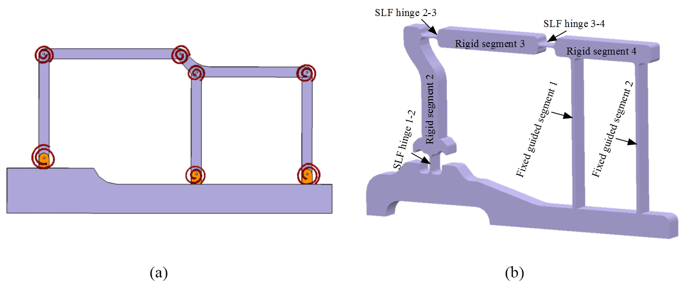
Figure 2(a) PRBM (b) isometric view of the mechanism whose slider is composed of fixed guided compliant segments.
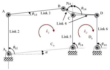
Initially, kinematic analysis of the PRBM which is essentially a rigid cascade parallelogram four-bar mechanisms is performed. The PRBM (Fig. 3) is formed as follows: input (link 2) and connecting rod (link 3) of the mechanism are combined with a parallelogram four-bar mechanism whose coupler link (link 4) acts as a slider of the fully compliant slider-crank mechanism (Fig. 2b).
Kutzbach criterion (Shigley and Uicker, 1980) for DOF of a planar mechanism is where j1 refers to the number of single DOF joints and j2 refers to the number of two DOF joints. The PRBM has six links and seven revolute joints. Thus, according to Kutzbach criterion, DOF of the mechanism is calculated as N=1.
Referring to Fig. 3, the revolute joints at A0, C0, and D0 are pivoted to the ground. Length of r1 is A0C0, length of link 2 is r2=A0A, length of link 3 is r3=AB. Link 4 that is formed by BCD is single piece and r8=BC, r4=CD, length of links 5 and 6 is . The horizontal distance between the revolute joints of the parallelogram four-bar is . θij are position variables measured counter-clockwise (in the right handed sense) from the horizontal axis. α is a constant angle between the horizontal axis and A0C0. γ54 is a variable angle between links 4 and 5 measured counter-clockwise from the vertical axis. Note that, γ54+θ14 is a constant angle.
The main objective of the position analysis is to derive closed form equations according to the position variables as a function of input angle θ12 and the structure parameters. There are two independent loops L1 and L2 as shown in Fig. 3. The relationship between the position variables, the structure parameters, and the input angle is obtained in Eq. (1) by substituting trigonometric identities into the loop closure equations.
However, obtaining a closed form relationship between θ12 and θ14 is very hard if not impossible. In the next section, we proposed an alternative method to obtain a closed form solution.
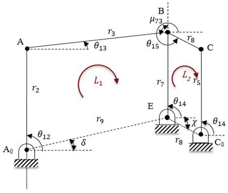
It is clear that link 4 performs curvilinear translation motion due to the parallelogram structure of the four-bar mechanism. Thus, any point on the coupler link moves on congruent curves. Points C and D performs fixed axis rotation about C0 and D0 respectively with a radius of curvature of r5. This brings us a very useful property for the analysis of the mechanism described as follows: let an imaginary link 7 is drawn parallel to link 5 between points BE (E is pivoted to the ground with a revolute joint) as shown in Fig. 4. The length of imaginary link 7; r7 is equal to r5 that is also equal to the radius of curvature. Furthermore, an imaginary link 9 is formed between points A0E with length of r9. Finally, an imaginary link 8 is drawn between points C0E with length of r8. Thus, an additional imaginary parallelogram four-bar mechanism is formed consisting links 4, 5, 7, and 8. Link 8 is parallel to CB and CB=r8. Referring to Fig. 3, δ and χ are constant angles between the horizontal axis and A0E, C0E respectively. μ73 can be called as the transmission angle between links 3 and 7. By this way, the new PRBM transforms to the mechanism in Fig. 4. This mechanism can be analyzed as two cascade four-bar mechanisms.
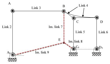
Initially, kinematic analysis of the first four-bar mechanism in Fig. 4, composed of links 9, 2, 3, and 7 is performed. θ14 is determined as a function of θ12 that is the input of the second four-bar mechanism. Next, kinematic analysis of the second mechanism (links 4, 5, 7, and 8) is performed. Now, all of the necessary position variables of the complete mechanism are determined in another way. Because, once the angle of link 7 w.r.t ground is found, the angles of the links 5 and 6 will be the same due to two coherent parallelograms; BEC0C and C0CDD0.
In order to obtain relationship between input θ12 and position variable θ14, the loop closure equation of the first four-bar mechanism can be written as:
Multiplying Eq. (2) by its complex conjugate, θ14 can be determined as a function of θ12.
where:
The coupler angle (θ13) of the first four-bar mechanism can be determined as
Considering the parallelogram shown in Fig. 5, θ15 can be determined as
Referring Fig. 3 input, output, and coupler link angles of the parallelogram mechanism are equal to each other (θ14). Therefore, after the kinematic analysis of the cascade four-bar mechanism, slider equivalent part of the mechanism can be readily analyzed.
During rigid body replacement synthesis, if the undeflected position of the compliant segment between rigid segments 3 and 4 is set to 180∘, the deflection of this compliant segment will be approximately same in both directions. In addition, μ73 is transmission angle of the PRBM, since the mechanism is equivalent to a slider-crank mechanism. If we define μ73=90∘ where the transmission angle is optimum, motion quality of the synthesized mechanism will be better. Note that for a compliant mechanism, compliance of flexural hinges may cause differences in transmission characteristics when compared to its rigid body counterpart (Tanık, 2011). However, it is verified that transmission characteristics of a compliant mechanism will be similar to those of its rigid body counterpart, if the output loading is large enough relative to the stiffness of compliant links (Tanık, 2011).
In this section, the design approach targets three main objectives. First objective is the minimization of the relative link rotations while maximizing the translational motion of coupler of the second four-bar mechanism. Because relative rotations of the links determine the deflection amount of the hinges of the compliant slider-crank mechanism. The second objective is to equate the relative rotation of links from a reference position. Because, it is well known that, equality of deflection in both directions minimizes deflection peaks in a compliant mechanism design. The third objective is to equate all relative rotations of the links to a specific value, if possible. By this way, all hinges of compliant slider-crank mechanism can be designed with same dimensions that yields a robust design. Generally, for compliant mechanisms, the dominant loading is due to bending. Bending stress is similar for the same hinges with same dimensions and deflections.
The design of the rigid body equivalence is performed considering these three objectives as follows: Initially, the first four-bar mechanism (A0ABE) is designed. This mechanism with input and output oscillations of Δβ (to obtain the same deflections) is synthesized by function generation for three precision points. The forward and fully withdrawn positions of the mechanism are presented in Fig. 6. Subscript f is used for the fully withdrawn positon that is represented with black lines, whereas subscript e is used for the forward positon that is represented by green lines in Fig. 6. Let the vertical position of links 2 and 7 corresponds to the undeflected position of the related flexural hinges. Also let the forward and fully withdrawn positions are achieved when links 2 and 7 move at an angle of Δβ∕2 from the vertical position.
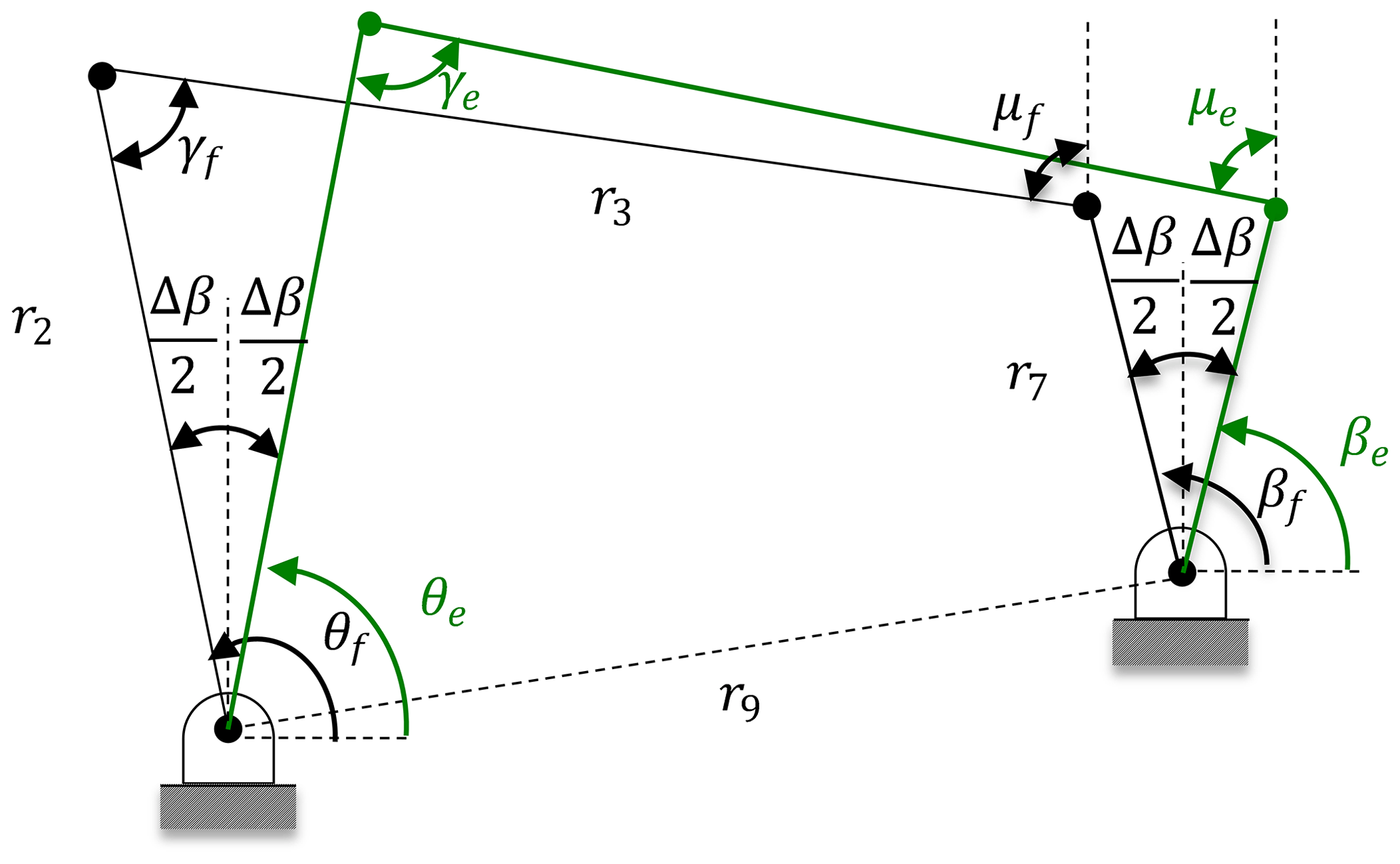
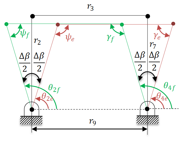
A parallelogram four bar mechanism as presented in Fig. 7 is a neat solution according to the requirements. Green, black, and red lines represent the fully withdrawn, undeflected, and forward positions of the mechanism respectively. With this approach, the angle between the extreme positions of links 2 and 7 is Δβ, and the undeflected position is exactly in the middle of these two positions. In other words, the extreme positions are symmetric with respect to the undeflected (vertical) position.
Considering the free design parameters, an infinite set of solution is available. However, in every solution it is determined that r2 and r7 are equal to each other that yields parallelogram four-bar mechanism. After function generation synthesis for three precision points, we obtained a solution where the complete mechanism is formed from two cascade parallelogram four-bar mechanisms. In Fig. 8 this mechanism is sketched in three positions that are undeflected, forward, and fully withdrawn positions. Remind that, r7 is equal to r5 that is obtained from the imaginary parallelogram four-bar mechanism. L can be chosen as a free design parameter as in Eq. (6).
Links 2, 3, 7, and 9 forms a parallelogram four-bar, therefore all of the compliant segments perform the same angular displacement between the forward and fully withdrawn positions of the mechanism as in Eq. (7).
Then, from parallelogram four-bar mechanism, the equality of r3 and r9 can be written as:
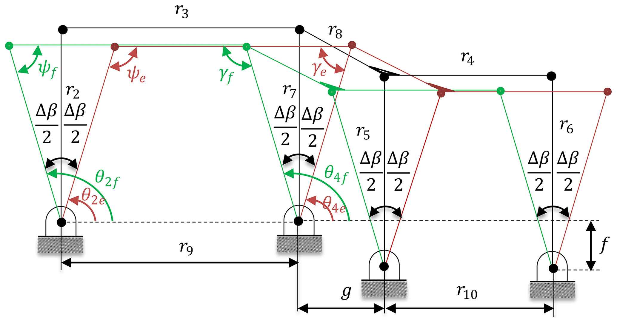
Figure 8Four-bar mechanism in three positions (forward-undeflected-fully withdrawn) with design parameters.
Kinematic analysis of the mechanism is simple due to the symmetrical link proportions: The stroke of the mechanism which is the horizontal motion of r4 is:
The axis drift of r4 can be defined as:
Generally, if deflections of flexural hinges are large, stresses of flexural hinges are also high. Thus, in practice, deflection values should be kept in a feasible range. By using the rigid body replacement method, the fully compliant slider-crank mechanism can be dimensioned as shown in Fig. 9.
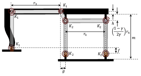
As shown in the PRBM, links 4–6 form a parallelogram four-bar mechanism where link 5 and 6 correspond to fixed guided beams. According to the length of the top and bottom parts of long compliant segments are equal to and length of the middle part is equal to γm which is also equal to r6; where γ is characteristic radius factor and it can be determined from reference (Howell, 2001) as: γ=0.852 for ∘. Rigid segments 3 and 4 are aligned. Thus, Eqs. (11) and (12) can be determined referring to Fig. 9 as:
where h is half thickness of upper rigid segment.
Note that, g, r3, and r4 are the free structure parameters. The value of the characteristic radius factor γ=0.8517 for n=0 and ϕ=90∘, with a parameterization limit of Θmax=64.3∘ for the flexible beam with a constant end angle and parametric angle coefficient cθ=0 (Howell, 2001). The moment, M0, that is required to maintain a constant end angle can be determined as:
Maximum stress occurs at both ends of the beam, where the maximum moment occurs and has a value of:
where, c is the distance from the neutral axis to the outer surface of the beam. The torsional spring constants, K1 and K2 for the springs are given in Eq. (15) as:
Maximum stress at complaint segments (Howell, 2001) CC0 and DD0 is:
The summary of the design procedure of the fully compliant slider-crank mechanism is presented in Table 1.
Table 1Design table of the fully compliant slider-crank mechanisms.
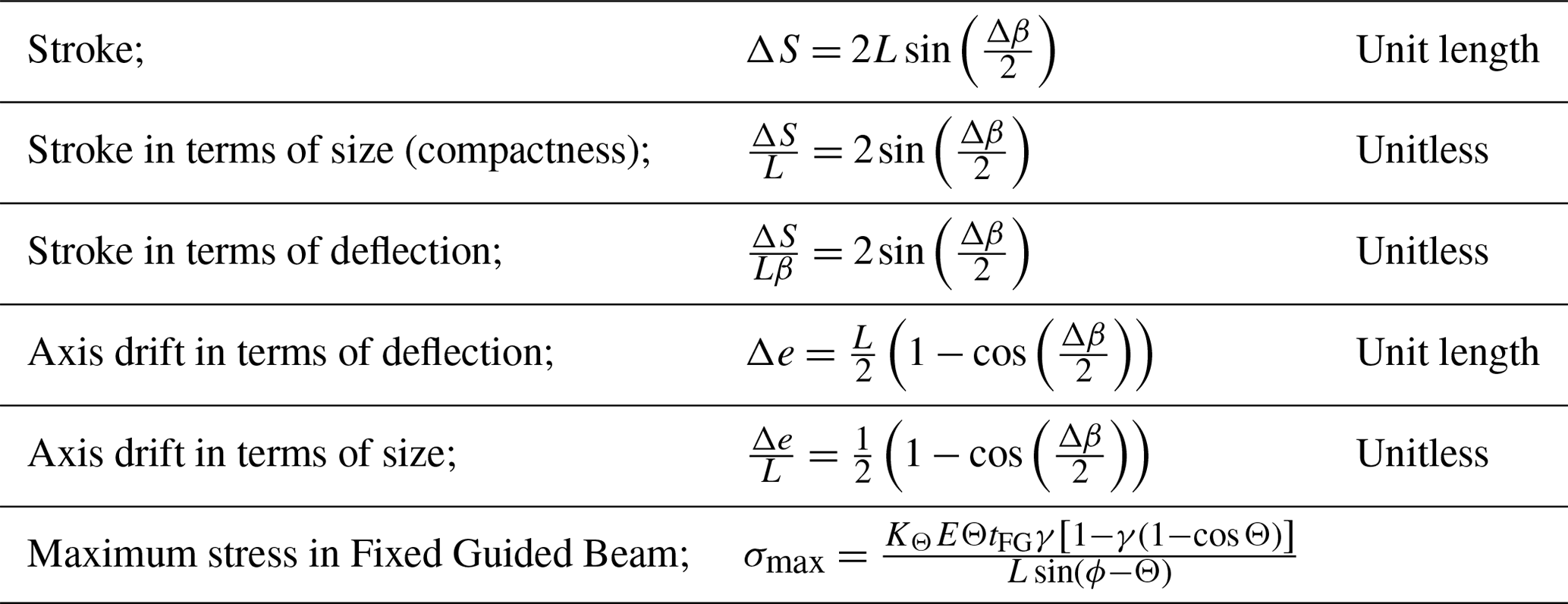
By using Table 1, numerous fully compliant slider crank mechanisms can be designed for different dimensions. This generalized design table will be beneficial during preliminary design stage satisfying very large slider strokes with acceptable stresses.
A fully compliant slider-crank mechanism is designed by using the method given in Sect. 6 and the equations in Table 1 as follows: let lengths of rigid segments 2, 4, and 6 be L=100 mm and Δβ=40∘. Material of the mechanism is selected as polypropylene which has modulus of elasticity E=1.5 GPa and yield strength of 40 MPa. The fixed guided beams are dimensioned as: thickness; tFG=2.85 mm, width; w=15 mm and length; m=117.4 mm, since L=100 mm and γ=0.8517. The stroke and axis drift of the slider are calculated analytically for Δβ∕2 from Eqs. (9) and (10). Stresses at the fixed guided beam are determined analytically from Eq. (16) as:
After the analytical design stage, by using rigid body replacement technique, a solid model of the mechanism is constructed. Then FEA method is employed to compare output stroke, axis drift of the slider, and resultant stresses at the flexural hinges. The fully compliant slider-crank mechanism is analyzed for different sets of input rotations (5, 10, 15, 20∘). For large rotations nonlinear analysis is selected. The resultant output stroke of the slider is presented in Fig. 10.
It is verified that, average of the output stroke and axis drift values of the slider are in close agreement with the analytical results. Resultant von-Mises stresses at the flexural hinges when the input rotation is set to its maximum value (20∘) are presented in Fig. 11. The analytical maximum stress value at compliant segments is determined as 34.4 MPa from Eq. (16), 32.9 MPa from FEA. The maximum stress value for the 20∘ input is smaller than the yield strength.
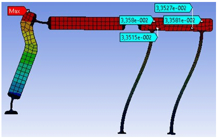
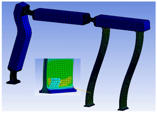
Figure 11Maximum stress values at compliant segments for fully compliant slider-crank mechanism.
A prototype of the mechanism is built for collecting experimental data. The mechanism is manufactured in one piece from polypropylene with a plate thickness of 15 mm. During the manufacturing process 3 axis CNC router is used setting 7.5 mm s−1 cutting rate, 1.5 mm depth of cut and 4500 rpm spindle speed. An experiment setup is established in order to measure the stroke and axis drift of the slider precisely as shown in Fig. 12. We compared the theoretical and experimental values as shown in Fig. 13. Note that position of the input is measured by a digital protractor and the output is measured by comparators.
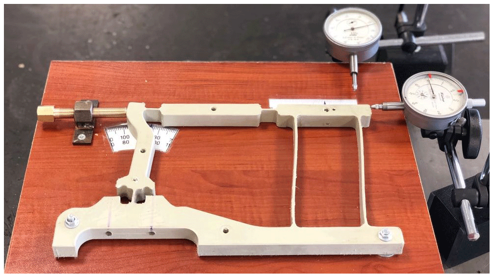
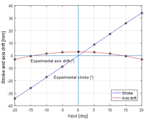
Figure 13Theoretical and experimental stroke and axis drift of the fully compliant slider-crank mechanism.
The datum point (zero axis drift position) is selected as follows: the datum axis is the mid-point of highest and lowest positions of the output. Note that, there are differences in error values for the left and right axis drifts. Because, fine manufacturing of the long compliant segments with classical machining process is very hard. The manufacturing error that deteriorates initial parallelism of the long compliant segments causes difference between theoretical and experimental results. If the prototype were produced by plastic injection molding with a metal mold as in a mass production case, we would be able to achieve smaller error values.
It is calculated that the mean absolute error of all data points for the stroke measurements is 0.13 mm. If this value is compared with the reference dimension L=100 mm, the error is 0.13 %. If this value is compared with stroke of the slider ΔS=68.4 mm, the error is 0.19 %. For the axis drift the mean absolute error of all data points is 0.09 mm. If this value is compared with the reference dimension L=100 mm, the error is 0.09 %. If this value is compared with the stroke ΔS=68.4 mm, the error is 0.13 %.
In the design of compliant mechanisms, there are always some errors due to roughness of PRBM approach. However, PRBM is not used for final dimensioning of a compliant mechanism. It is a tool which is used during the preliminary design stage. Precise dimensioning of compliant mechanism is generally finalized with finite element analysis tools. The design approach in this study is no exception to this issue.
Slider-crank is one of the most commonly used mechanisms in the industry and has numerous applications. In the literature, studies on “partially” compliant slider-crank mechanism can be found where the slider is a rigid joint. There are some fully compliant slider-crank mechanisms available however those are not optimized for large stroke and minimum link rotation. In this paper, a novel design procedure for a fully compliant slider-crank mechanism is proposed. In this design, the prismatic joint is replaced with a compliant parallel-guiding mechanism. The compliant parallel-guiding mechanism is the output of the system that performs curvilinear translation provided that the output is not loaded with large forces. The novelty of this design approach is the slider's large stroke capacity. It is achieved by maximizing the translational motion of the slider while minimizing the relative link rotations thus stresses in compliant links.
A design approach for optimum link proportions of the PRBM of the fully compliant slider-crank mechanism is proposed. Input-output motion relationship of the mechanism and analytical stress values at flexural hinges are determined. In order to generalize the design approach, a procedure is employed and finally a design table that can be used for various tasks is presented. This table will be very beneficial for compliant slider crank designers.
As an example, a mechanism is synthesized using the design table. This mechanism is analyzed with FEA method to verify analytical results. It is shown that the results of the proposed theoretical model and FEA model are consistent. Finally, a single piece prototype is manufactured from polypropylene; thus, it has the advantage of ease of manufacturing when compared with the partially compliant mechanisms. Experimental setup is employed for stroke and axis drift measurements. It is observed that the output displacement and axis drift in the mathematical and the prototype are almost the same. Thus, it is verified that the proposed methods are consistent.
As a result, validity of the design approach is ensured by two ways. It is remarkable that the maximum error between the theoretical model and prototype is less than 0.2 % (for slider stroke). This is a negligible error for a mechanism designed via PRBM approach where generally noticeable errors take place.
We believe this fully compliant slider-crank mechanism design procedure will be beneficial for many designers and may find many applications especially where backlash free design is required.
Data can be made available upon reasonable request. Please contact Engin Tanık (etanik@hacettepe.edu.tr).
The video file of the prototype is available at https://www.youtube.com/watch?v=wtjVkuwpUMg (last access: 6 February 2020).
ET proposed the original design and defined the methodology. ÇMT applied the methodology, performed analytical solutions, employed FEA, and wrote the paper. VP studied on the theoretical model. YY supervised ÇMT during the study.
The authors declare that they have no conflict of interest.
This paper was edited by Lionel Birglen and reviewed by three anonymous referees.
Alqasimi, A., Lusk, C., and Chimento, J.: Design of a linear bistable compliant crank–slider mechanism, ASME J. Mech. Robot., 8, https://doi.org/10.1115/1.4032509, 2016.
Dao, T. P., and Huang, S. C.: Design and Analysis of Flexible Slider Crank Mechanism, Int. J. Aerosp. Mech. Eng., 8, 836–843, https://doi.org/10.5281/zenodo.1337163, 2014.
Erkaya, S., Doğan, E., and Şefkatlıoğlu, E.: Analysis of the joint clearence effects on a compliant spatial mechanism, Mech. Mach. Theory, 104, 255–273, 2016.
Hao, G., Li, H., Nayak, A., and Caro, S.: Design of a Compliant gripper with Multi-mode Jaws, J. Mech. Robot., 10, 031005, https://doi.org/10.1115/1.4039498, 2018.
Hongzhe, Z., Shusheng, B., and Jıngjun, Y.: A novel compliant linear-motion mechanism based on parasitic motion compensation, Mech. Mach. Theory, 50, 15–28, 2012.
Howell, L. L.: Compliant Mechanisms, John Wiley & Sons, Inc., New York, USA, 2001.
Howell, L. L. and Midha, A.: A loop-closure theory for the analysis and synthesis of compliant mechnasims, ASME J. Mech. Design, 118, 121–125, 1996.
Li, X. C., Li, Y., Ding, B. X., and Xu, H. Y.: An investigation on kinematics and dynamics performance of a novel 3-PRC-compliant parallel micromanipulator, Adv. Mech. Eng., 10, 1–9, https://doi.org/10.1177/1687814018789800, 2018.
Liu, P. and Yan, P.: A modified pseudo-rigid-body modeling approach for compliant mechanisms with fixed-guided beam flexures, Mech. Sci., 8, 359–368, https://doi.org/10.5194/ms-8-359-2017, 2017.
Pardeshi, S., Kandharkar, S., and Deshmukh, B.: Monolithic compliant slider crank mechanism for motion, Proc. Mater. Today, 4, 1677–1682, https://doi.org/10.1016/j.matpr.2017.02.007, 2017.
Parlaktaş, V. and Tanık, E.: Single piece compliant spatial slider-crank mechanism, Mech. Mach. Theory, 81, 1–10, 2014.
Pavlović, N. T. and Pavlović, N. D.: Compliant mechanism design for realizing of axial link translation, Mech. Mach. Theory, 44, 1082–1091, 2009.
Shigley, J. E. and Uicker, J. J.: Theory of Machines and Mechanisms, McGraw-Hill Book Co., New York, USA, 1980.
Tanık, E.: Transmission angle in compliant slider-crank mechanism, Mech. Mach. Theory, 46, 1623–1632, 2011.
Trease, B. P., Moon, Y., and Kota, S.: Design of large displacement compliant joints, ASME J. Mech. Design, 127, 788–798, 2005.
Yang, T. S., Shin, P. J., and Lee, L. L.: Design of a spatial compliant translational joint, Mech. Mach. Theory, 94–114, 2016.
Yu, Y. Q., Zhu, S. K., Xu, Q. P., and Zhou, P.: A novel model of large deflection beams with combined end loads in compliant mechanisms, Precis. Eng., 43, 395–405, https://doi.org/10.1016/j.precisioneng.2015.09.003, 2016.
Zhao, H., Han, Z., Zhang, L., and Shusheng, B.: Design of a stiffness-adjustable compliant linear-motion mechanism, Precis. Eng., 48, 305–314, 2017.
- Abstract
- Introduction
- The proposed fully compliant slider-crank mechanism
- Kinematic analysis of the cascade parallelogram four-bar mechanism
- A novel kinematic analysis approach for the PRBM
- Design approach of the rigid body equivalent of the compliant slider-crank mechanism
- Design of the fully compliant slider-crank mechanism
- A design example
- Discussion and conclusion
- Data availability
- Video supplement
- Author contributions
- Competing interests
- Review statement
- References