the Creative Commons Attribution 4.0 License.
the Creative Commons Attribution 4.0 License.
 | 06 Jul 2020
Spatial cellular robot in orbital truss collision-free path planning
Ye Dai
Zhaoxu Liu
Yunshan Qi
Hanbo Zhang
Bindi You
Yufei Gao
Aiming at the problem of moving path planning of a cellular robot on trusses in space station, a triangular prism truss is taken as the research object, and an optimized ant colony algorithm incorporating a gravitational search algorithm is proposed. The innovative use of the hierarchical search strategy which limits the exploration area, the use of gravity search algorithm to get the optimal solution of truss nodes, and further transform it into the initial value of pheromone in ant colony algorithm, can effectively prevent the algorithm from falling into the local optimal solution in the early stage, and make the optimization algorithm have a faster convergence speed. This paper proposes a heuristic function including the angle between the targets, which can effectively avoid blind search in the early stage and improve the ability of path search. The simulation results show that the path and planning time of the cellular robot can be effectively reduced when choosing truss path.
- Article
(5552 KB) - Full-text XML
-
Supplement
(236 KB) - BibTeX
- EndNote


With the rapid development of space technology and robotics, and the increasing demand for space resources exploration, the scale of the corresponding spatial structure and the level of on-orbit operations have also ballooned, such as solar space stations, large space mirrors, their size can reach the kilometers (Zhao and Han, 2018). Space exploration has become a focus of the future development of the aerospace field. Therefore, it is an important direction of research for the current space robot that draws on reconstruction robot technology and swarm robot technology and applies them to the construction of space facilities to improve its operating ability and adapt it to complex working environments (Wei and Li, 2011).
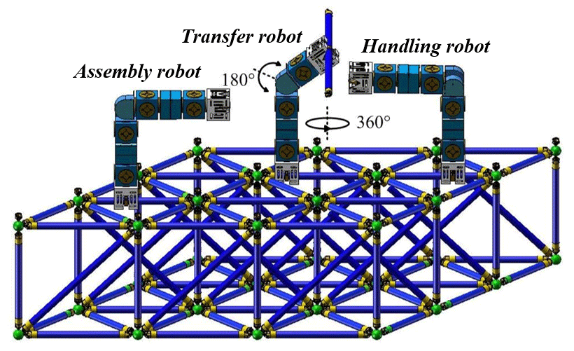
At present, the on-orbit construction of large-scale space facilities mainly depends on the simple assembly of space manipulator and transposition mechanism. The transfer and assembly of large-scale system of space manipulator on orbit has the disadvantages of poor structural rigidity, low precision and energy consumption, and its own structure and base mobility range seriously limit its operation range; the mechanical form of on orbit work is fixed, and the function is single, which can not meet the needs of multiple assembly tasks. Because the large space truss is difficult to launch in one time, it needs to be launched in modules and then assembled in orbit, so there will be assembly and path planning problems. As shown in Fig. 1, the modular space cellular robot can work in the space station and other space environments. Modular robot is considered to be an ideal substitute for high-rise truss related tasks. It can move flexibly on the complex three-dimensional truss, especially the ability to move quickly from the initial position to the target position, which is crucial to the efficiency of path planning.

The Spatial cellular robot mentioned in this paper is a multi-level self-reconfigurable modular robot with high reliability, variable configuration and easy function expansion. Self-reconfigurable modular robots are composed of a series of common modules, which can meet the needs of corresponding tasks according to the changes of the environment or tasks, relying on the separation, displacement and docking between modules. Research on it has become a hot spot in academic and industrial circles in recent years (Zhu et al., 2018).
After a long-term study, it is shown that there are many disadvantages in manned on orbit assembly technology. Due to the participation of astronauts, the operation cost of on orbit assembly is greatly increased, and space on orbit operation poses a threat to the safety of astronauts. Due to the special environment of space, the astronauts can not bear the heavy workload for a long time, so the development of unmanned on orbit assembly technology is particularly important. Unmanned on orbit assembly technology is a kind of on orbit assembly task which is operated by intelligent equipment such as space robot mechanical arm, remote control on the ground or autonomously. Unmanned on orbit operation avoids the astronauts' on orbit participation, effectively improves the safety and reliability, greatly reduces the operation cost, and is easier to achieve popularization. Based on the current hardware and software platform, self-reconfigurable modular robots can complete complex operational tasks in the future (Liu et al., 2018).
Figure 2 shows the space cell robot independently designed by the project, which is composed of four functional modules. The grabbing cell module can realize the grabbing of truss and the overall movement, the rotating cell module can realize the 180∘ rotation of the module, the interstitial cell module can connect different functional cells, and the rotating cell module can realize the 360∘ rotation of the module. It can be combined according to the task requirements to achieve multiple functions.

As shown in Fig. 3, the four cell function modules can be combined according to different task requirements, and can complete truss rod handling, collaborative assembly and other tasks in the assembly process of triangular truss. In the process of truss assembly, space cellular robot can achieve the following three functions: grabbing and carrying truss parts, assembling truss, and adjusting the relative installation position of truss. Specifically, it can make the robot have different degrees of freedom of operation and satisfy the operation function of the robot to the greatest extent by cooperating with three kinds of combined robots, namely, the handling robot, the transfer robot and the assembly robot, and fully considering the operation characteristics and requirements of the three kinds of robots. To ensure that the space cellular robot can form a truss assembly team, coordinate and orderly complete the space truss on orbit assembly work.
At present, the installation, inspection, maintenance and other work related to trusses highly depend on labor, and robots are an ideal substitute for performing these high-intensity tasks (Wei and Wang, 2010). By consulting the relevant literature, it is known that SM2 is designed for free execution of space station trusses and other daily tasks (Tan et al., 2018). Gu et al. (2018) proposed a path planning method for checking the reliability of truss nodes. Alberto et al. (2019) proposed a path planning algorithm to optimize the shortest distance problem of a moving robot on a truss. Chung and Xu (2013) proposed a new genetic operator using the concept of genetic modification, which solved the minimum energy problem required for mobile robots in climbing paths in space stations.
Obstacle avoidance is the basic problem of Spatial cellular robot path planning. Sun et al. (2019) proposed an improved artificial potential field method, considering the distance between robot and obstacle in path planning Liang and Lee (2015) proposed an efficient artificial bee colony algorithm (EABC) with obstacle avoidance strategy based on artificial bee colony to solve online path planning for multi-mobile devices. Qi et al. (2017) proposed a method based on probability theory for obstacle avoidance trajectory. By establishing a Gaussian motion model and using Gaussian motion prior probability estimation to get the optimal path trajectory. Although the path planning method based on the teaching programming mode is workable, it is difficult to get the best path in this way, and the path planning takes too long (Wang et al., 2017).
After the environment modeling is completed, an appropriate path search algorithm is needed to find the optimal path. Ant colony algorithm is a heuristic intelligent search algorithm, which is well applied in solving path planning problems (Wang et al., 2019). Because ant colony algorithm has the disadvantage of being easy to fall into local optimum and difficult to get rid of dead point, Jiang et al. (2019) proposed an improved ant colony optimization algorithm which improves the overall efficiency of the algorithm and the working efficiency of the mobile robot by improving the quality ant pheromone principle. Wei and Ren (2018) proposed a fast-exploration random tree (RRT) algorithm based on random sampling, which has the advantages of completeness of probability, complete expansion and rapid exploration speed, and it is used in dynamic high-dimensional path planning.
Because there are few studies on truss path planning at home and abroad, the above research has the following three characteristics: (1) There is no combination of path optimization and obstacle avoidance, which leads to the risk of collision or even damage in the path planning of robot, which has limitations. (2) The collision free path planning takes a long time, which leads to the repeated paths of the robot in the path planning, and the mobile efficiency is low. (3) The improved algorithm is relatively simple, and there is no fusion reference between different algorithms to optimize one of them.
The main research goal of this paper is to optimize the existing algorithms of space cellular robot under the premise of working environment of triangular truss, so that the cellular robot can find an optimal path to meet the requirements of the task according to the overall model of the truss built in advance, and carry out the global path planning, so as to improve the initial position of the cellular robot It can reduce the unnecessary moving distance, reduce the energy consumption of the robot, and ensure the robot to reach the designated working position efficiently and safely.
We organize the paper as follows. The first part introduces the important prospect of space cell robot and the practical application of path planning. In the second part, the truss path planning of cellular robot is studied and the spatial model is established. The third part divides the three-dimensional space of the whole truss into regions, and designs an optimized ant colony algorithm based on the ant colony search strategy and the universal gravitation search algorithm. By limiting the effective search range of the target, the search time and distance of the shortest path can be shortened. The fourth part carries on the path planning simulation experiment, compares the performance parameters of the traditional ant colony algorithm and the improved optimization algorithm, and analyzes the results. In the fifth part, on orbit assembly experiments are carried out to verify the rationality of on orbit assembly movement through virtual simulation. The sixth part is the conclusion of this paper.
Anh et al. (2018) proposed a new global path planning method based on A-star algorithm for self reconfigurable Tetris cleaning robot. This method aims at the largest coverage area and covers narrow space by generating path points to ensure excellent area coverage performance. Su et al. (2011) proposed a motion planning and coordination strategy suitable for different types of robots in different tasks. Experiments on robot path planning and mobile robot system coordination were carried out to verify the effectiveness and generality of the method. Hou et al. (2014) proposed a reconstruction path planning algorithm called MDCOP, which can find an approximate solution in polynomial time and generate the optimal reconstruction path planning based on graph.
2.1 Establish the truss space model
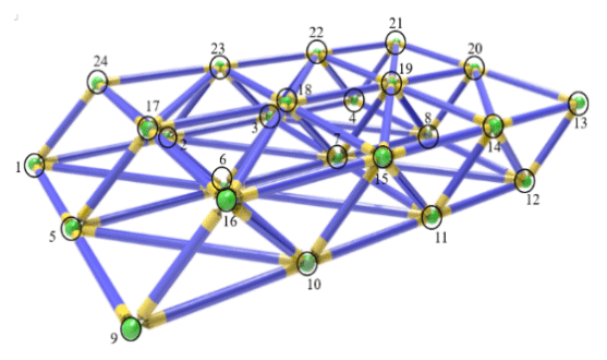
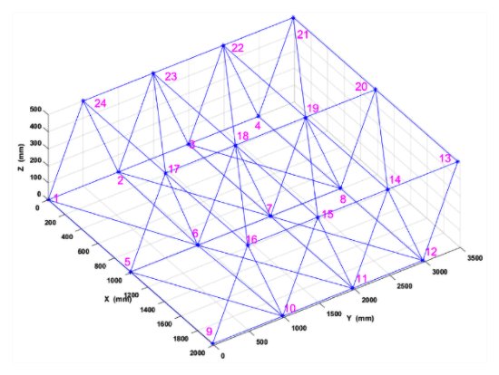
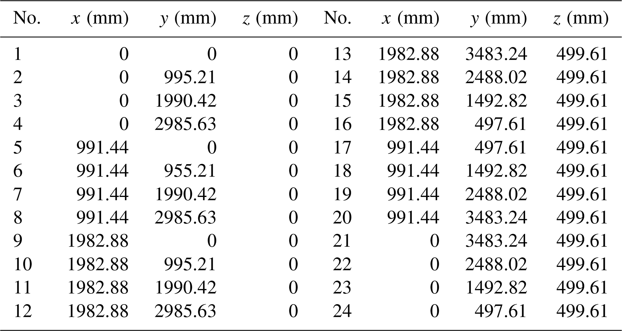
When constructing a single-layer triangular prism truss group, the Spatial cellular robot uses 24 truss ball heads as path nodes to plan the path. The coordinates of the truss ball head are got by “RobotStudio”. The center point of the green ball head in the figure is used as the coordinate of the space node, the workpiece coordinate system is established, and the coordinate data is imported into the “Matlab” environment to generate the space model. As shown in Fig. 4, this paper studies the path planning of the starting point 9 moving to the target point 21.
2.2 Space division in the orbital truss area
Extend two-dimensional space to three-dimensional space by grid methods: As shown in Fig. 6, the three-dimensional space model space ABCD-EFGH is established in the O-xyz coordinate system, where ABCD is a square with a side length of 2l. The coordinate system is established by using point A as the coordinate origin, so that the ABCD plane is in the xOz plane, AE is n-divided along the y-axis direction, AB is equally divided in the x-axis direction, and AD is equally divided along the z-axis direction. n planes can be obtained, and each plane is divided into m×l grids by grid division.
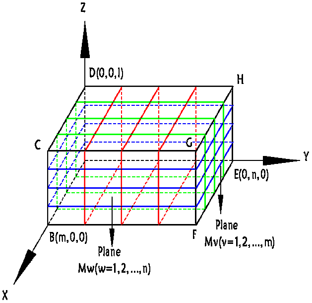
The space ABCD-EFGH is processed into cubes by grid method, and each small cube corresponds to the associated spatial discrete point coordinates and the position of each coordinate point is calculated by the formula, as shown in Eq. (1).
2.3 Truss three-dimensional path distance planning
According to the description of the three-dimensional model, the starting point of the space truss cell robot is Ps, and the target point is PE. Moving from the initial point to the target point needs to pass through the n-plane Mj, that is, to ensure that the ant has a reachable area when searching for the next node. First, the ant starts from the starting point Ps, searches for the feasible node in the first M1 plane, and then searches for the feasible node on the second M2 plane. The feasible nodes on each plane are selected, and finally the target point PE is reached, and an optimal path search is completed.
The distance between the nodes Pj and Pj+1 on any two adjacent planes Mj, Mj+1 is defined as:
Where is the distance between any two plane nodes.
According to the above path node distance definition, the three-dimensional optimal path planning problem is transformed into solving the shortest distance problem of the path node sequence from the starting point Ps to the target point PE.
Combine the Eq. (1) path distance to:
3.1 Designing a multivariate heuristic function
In this paper, the heuristic function in the ant colony algorithm is designed with the shortest path, algorithm convergence and obstacle avoidance as the optimization indicators. The heuristic information includes obstacle avoidance coefficient factors, distance factors, and the angle factors proposed in this paper to form a multivariate heuristic function.
3.1.1 Obstacle avoidance factor heuristic factor
In this paper, the obstacle avoidance coefficient model of discrete points is introduced. According to the traffic of discrete points divided by three-dimensional workspace, the feasibility of the discrete point set S of the searchable region of the point Pw in the planning space is feasible. Assignment, quantity statistics, calculation of feasibility factor weights.
In the formula (4), is the weight of the discrete points in the discrete point set S in the plane searchable region, and the pass point weight is otherwise 0.
where μ1 is the number of unobstructed discrete points in the plane Mw,v, and μ is the plane Mw,v to explore the number of discrete points in the area.
3.1.2 Gravitational coefficient heuristic factor
Here the gravitational factor in the idea of universal gravitation search is introduced. Based on the distance feature between the two nodes in the three-dimensional space, ant colony algorithm is given a preliminary guiding direction, and the attraction factor of the target point is selected. The rapid convergence, the establishment of the gravitational coefficient model Qw can greatly increase the time validity of the algorithm, reduce the convergence time of the algorithm, and ensure that the search direction of the shortest path follows the optimal direction of the shortest target.
where Q is the coefficient of gravity in the heuristic function.
3.1.3 Target angle heuristic factor
This paper proposes a heuristic factor for the angle of the target node. The path planning in the 3D workspace requires high space complexity. In this paper, the target clip consisting of the current point Pw, the starting point Ps and the target point Ps of the ant K is introduced. Angle θE, as shown in Fig. 7.

The specific definition of the angle θE is as follows:
In the formula, the included angle θE is defined as the angle between the vector PsPE and the vector PwPE, as shown in the figure, select within the searchable area Mw,v makes θE tend to the target angle. The angle φE is favorable for the path planning search direction to approach the target point PE. The target angle φE is defined as follows:
In the formula, ε is an angle adjustment parameter greater than zero, the purpose is to prevent φE from being too small to zero. Combining Eq. (9), the target angle heuristic factor is defined here as:
In the formula, ξ represents the angle factor, because the exploration area Mw,v can be farther away from the target point in the initial stage of the path planning, and the front stage is increased, avoiding the angle range being too large and causing blind search; the path planning is reduced later. Thereby enhancing the accuracy of path planning. The angle factor ξ is defined as follows
In the formula, ξ0 represents the initial value of the angle factor, Nc, Ncmax represents the number of iterations and the maximum number of iterations of the path planning algorithm.
3.1.4 Constructing a dynamic multi-heuristic function
Here, the multi-heuristic function is constructed by combining the formula (6), the formula (7), and the formula (10).
where H is the multivariate heuristic function.
3.2 Stratification can explore the ant colony search strategy in the region
Due to the expansion of the choice of three-dimensional space, the idea of two-dimensional spatial plane search cannot be continued. The hierarchical search mode of the discrete three-dimensional path planning space can be explored here.
3.2.1 Hierarchical Search Strategy
The stratified search dimension reduction strategy is used to transform the 3D path planning grid space problem into multiple 2D problems. The spatial layering is discrete into a 2D plane which reduces the complexity of the environment. Degree and optimization time can effectively solve the problems of program stuck and slow solution caused by blind group discrete search mode of ant colony.
3.2.2 Explore the node selection strategy in the area
The restricted searchable area strategy is adopted to make the discrete two-dimensional plane into several searchable areas Mw,v.
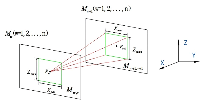
As shown in Fig. 8, the y-axis direction is defined in the 3D path planning space as the main direction of the path planning for bisector plane dispersion. When the ant K is the point Pw on the aliquot plane Mw, the maximum lateral movement grid number of the ant K in the x-axis direction is defined as xmax and the maximum moving grid number in the z-axis axis direction is Zmax; A searchable area with a grid number of xmax×zmax is formed on the plane such that the node selection of each ant k falls within the searchable area.
3.3 State probability transfer rules
In the process of ant colony algorithm path planning, when ant K is located at point on the Mw plane, then the searchable area located in the Mw+1 plane is selected according to the state probability transfer rule. (w+1, v+1) a point as the transfer node, here we combine the last section The constructed multi-heuristic function (12) obtains the state probability transfer rule for the three-dimensional path planning space:
where is the current pheromone content of the point Pw+1 corresponding to the searchable region , is a heuristic function, allow K is a collection of ants K to be visited. α reflects the importance of the previous ant colony's inspiration to the current ant, and β indicates the importance of the current local environment's inspiration to the ant.
3.4 Ant colony pheromone update based on gravity search
The universal gravitation search algorithm is to find the optimal solution by moving the gravitation among population particles in the search space. This paper proposes to use the strong global search ability and search speed of the gravity search algorithm to search the path of the entire region in order to get the optimal solution and transform the got result into the initial pheromone in the ant colony algorithm. This solves the problem that the original node pheromone distributed in the traditional ant colony algorithm is easy to fall into local optimum and search blindness, and accelerates the path planning search speed by the gravity search algorithm.
According to the law of universal gravitation, the positional update is performed by using the D-dimensional velocity and the position , and assign the pheromone value to the path node of the workspace and correspond to one pheromone value according to the coordinate value.
The gravitational heuristic factor Qw in the improved ant colony algorithm is introduced as the Euclidean distance between the particle i and the particle j in the equation, and ε is a tiny constant, and we set the parameter to prevent the denominator from being zero.
represents the force between particle i and particle j, Mi and Mj represent the inertia mass of particle i and particle j, worst (t) and best (t), respectively, taking the difference and optimal value of fiti(t). randi represents the random number between intervals [0,1], represents the position of particle i in d-dimensional space, represents the velocity of particle i in d-dimensional space, represents the acceleration of particle i in d-dimensional space.
The spatial optimal solution obtained by the gravitational search algorithm is transformed into the initial pheromone in the ant colony algorithm. When the ant k completes a search iteration, the pheromone content of the nodes on the better path in this iteration is selected for global update, and the ant k is transferred from the current point to a point before the current point. Perform real-time pheromone updates:
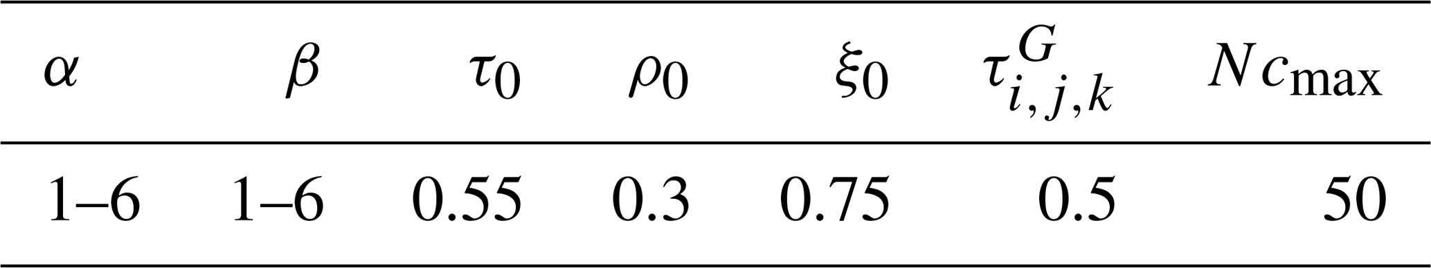
where is the pheromone content of the current point Pw, is the initial value of the pheromone content of each point, with a value of 0.5. ρ is the pheromone content attenuation coefficient, ρ0 information The initial value of the attenuation coefficient, with a value of 0.3. Nc represents the current number of iterations of the statistical algorithm; Ncmax is the maximum number of iterations of the algorithm, with a value of 50.
3.5 The overall flow of optimized ant colony algorithm for fusion gravity search
The Spatial cellular robot global path planning diagram is shown in Fig. 6. This algorithm is based on an optimized ant colony algorithm and integrates gravitational search operations. Its path planning is the food search process of ant colonies. Communication between ants is achieved by pheromones. The shortest path can be found through mutual cooperation between ant colonies. The corresponding flow chart of fusion algorithm for path planning is as shown in Fig. 9.

The collision-free path planning procedure based on the fusion universal gravitation search algorithm is as follows:
-
Step 1: Establish a three-dimensional environment model for the spatial cellular robot working environment, generate a three-dimensional spatial discrete node set .Initialization parameter, initial velocity of particle , initial acceleration , number of ants Ncmax, heuristic factors α and β, initial value of pheromone attenuation coefficient ρ0, initial value of angle coefficient ξ0.
-
Step 2: Select the starting point and the target point to facilitate the planning of the distance between nodes and the global map information in the path planning problem in the discrete grid space model.
-
Step 3: Calculate the particle fitness function fiti(t) and update the interparticle attraction .
-
Step 4: Perform a rough search and update the particle-related locations .
-
Step 5: If t>tmax, proceed to the next step, otherwise, let and go to step 3.
-
Step 6: Convert the optimal or suboptimal solution of the path plan obtained by the gravity search algorithm into the initial value of the pheromone and update the pheromone distribution.
-
Step 7: Use the stratification strategy to divide the 3D space model into planes and limit the searchable area of each aliquot plane . And define the maximum lateral distance xmax and the maximum longitudinal distance zmax of ants. According to the prior information of spatial model, the maximum number of layers wmax and the maximum number of explorable regions vmax are defined.
-
Step 8: Let w be assigned a value of 1.
-
Step 9: v is assigned a value of 1, Nc is assigned a value of 1.
-
Step 10: Place the ant k definition on the searchable area Mw,v in the plane Mw of Pw.
-
Step 11: Calculate the current point Pw corresponding to the multivariate heuristic function according to the formula.
-
Step 12: The ant Nc selects a point Pw+1 located in the searchable area in the plane Mw+1 according to the state probability transition probability rule, and the ant Nc The pheromone content of the current node Pw is updated in real time.
-
Step 13: If v>vmax, proceed to the next step; otherwise, let and jump to step ten
-
Step 14: If w>wmax, proceed to the next step; otherwise, let and go to step nine.
-
Step 15: Determine the better path Pathb and update the pheromone content of the node on the better path Pathb obtained by this iteration.
-
Step 16: If Nc>Ncmax, proceed to the next step; otherwise, let , and jump to step 12.
-
Step 17: Output the optimal path Pathb(Nc).
4.1 parameter selection of traditional ant colony algorithm and improved optimization algorithm
In order to verify the effectiveness and superiority of the improved optimization algorithm, matlab2018b simulation software is used to simulate the traditional ant colony algorithm and the improved optimization algorithm in this paper. The path planning process of space cell robot in three-dimensional truss working environment is simulated. Because the simulation process of ant colony algorithm uses roulette, each simulation result will have deviation, so in the simulation, each algorithm in the experiment is simulated many times, and the average value is taken to verify the effectiveness of the improved optimization algorithm. The computer CPU model is an Intel(R) Core(TM) 5 Quad CPU 9300H, and the internal storage capacity is 8 GB.
The selection of parameters of ant colony algorithm is usually based on the experience value, through the experiment comparison, get the better parameters. Mainly for the selection of parameters α and β, the value range of α and β is [1–6], the other parameters are compared according to experience and experimental simulation, and the value is shown in Table 2.
α represents the importance of the previous generation ant colony to inspire the current ant, and β represents the importance of the current local environment to inspire the ant. The value of β∕α is taken as independent variable, and the path evaluation index Im(n) is taken as dependent variable. In order to facilitate the experiment, set the value range of α and β as [1–6], each interval of 0.2 as a value point, and the formula is shown in Eq. (20).
In the formula, Im(n) represents the path evaluation index, as the evaluation standard of path planning length, the lower the value is, the shorter the path distance is. Lm(n) represents the path length of the m ant in the nth iteration. hm(n) represents the mean square deviation of grid space height. Tm(n) represents the turning times of nodes in path planning. i, j, k represent the adjustment coefficient of each factor. The value is taken according to the required path property, and the default value is 0.1. The results are shown in Fig. 10.
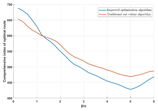
The results show that when the β∕α ratio is small, the empirical factors play a major role, and the probability of ants repeatedly passing through the path nodes is large, which weakens the effectiveness and accuracy of the search. When the ratio of β∕α is large, the deterministic factors play a major role. Ants tend to choose the minimum value of the path index, which makes the algorithm have a faster convergence speed. When the ratio of β∕α is about 5, the algorithm has a wide range of search and the path index obtained is the best Path. Therefore, when α=1 and β=5, both the traditional ant colony algorithm and the improved optimization algorithm can play the best performance.
4.2 space truss path planning simulation
In the MATLAB environment, the three-dimensional path of the Spatial cellular robot on the truss is simulated. According to the above steps, a single-layer triangular prism truss group is selected, and we set the mounting balls 9 and 21 as the starting point and the target point. The size of the robot is not considered in the simulation experiment, so the planning path almost coincides with the edge of the truss.The planning results of the traditional ant colony algorithm and the optimized ant colony algorithm path are shown in Fig. 11.
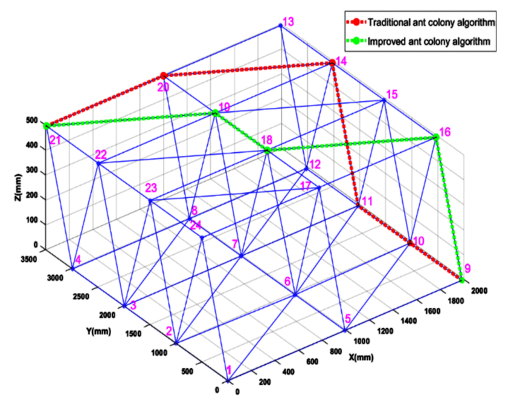
Through the above steps, the shortest collision-free moving path of the cellular robot that can be realized based on the traditional ant colony algorithm is: , and the optimal path length is 4795.000 mm. The shortest collision-free moving path based on gravity search-optimized ant colony fusion algorithm is: , and its optimal path length is 4502.546 mm. By comparison, we can clearly find it that the shortest path based on the optimization algorithm is better.

Figure 12Iterative comparison process between traditional ant colony algorithm and improved ant colony algorithm.
Figure 12 is a comparison of the convergence curves of the algorithm. Figure 12a and b are the convergence curves of the traditional ant colony algorithm and the optimized ant colony algorithm. It is obvious from the comparison that we show the convergence of the optimized ant colony algorithm. The speed is faster, and the shortest moving path of its spatial cellular robot is shorter than the path of the traditional ant colony algorithm. From the trend of convergence curve, the curve of the optimized ant colony algorithm is gentle and small, which shows that the convergence of the optimized ant colony algorithm is better. We can see it from Table 3 that the Spatial cellular robot based on the optimized ant colony algorithm is the best. The path is shorter and better than the traditional ant colony algorithm path; and the optimized ant colony algorithm is less than the traditional ant colony algorithm in the number of iterations, which proves the superiority of the improved algorithm.
As can be seen from Fig. 12, the previous iteration of traditional ant colony algorithm is unstable and prone to local optimization. Because of the improved search strategy and pheromone distribution rules, the overall iteration curve of this improved algorithm shows a downward trend. After the later stage is stable, the shortest path length obtained by the improved algorithm is also shorter, and the path evaluation index and iterative stability times of the algorithm in this paper are better than the traditional ant colony algorithm.
Select different iterations N and ant colony number Nc to verify the effectiveness of the optimized ant colony algorithm. The maximum value, minimum value, average value, path variance and response time of each condition are shown in Table 3.
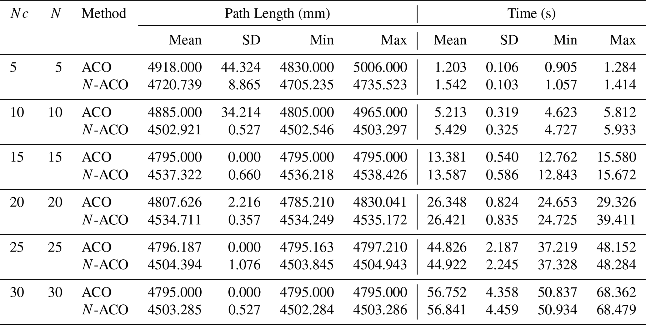
Further, through Table 3, When the iteration number N and population size NC of traditional ant colony algorithm (ACO) are 5, the local optimal path length is 4830.000 mm, the average path length is 4918.000 mm, the adjustment time is 0.905 s, the planning time is 1.203 s, and the operation efficiency of planning time is 75.2 %.
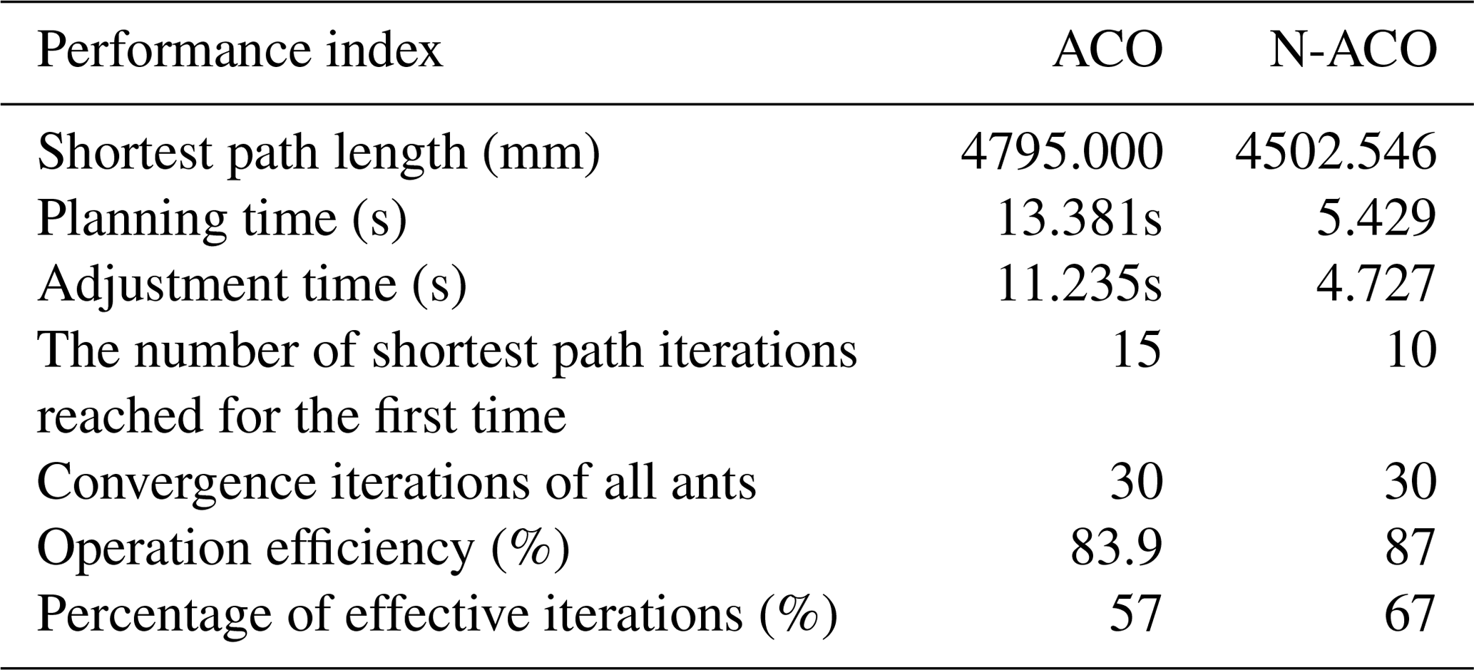
When the iteration number N and population size NC of traditional ant colony algorithm (ACO) are 15, the shortest path length of cellular robot on truss is 4795.000 mm, the average path length is 4795.000 mm, the adjustment time is 11.235 s, the planning time is 13.381 s, and the operation efficiency is 83.9 %. For the first time, the number of shortest path iterations is 15, the number of convergence iterations of all ants is 30, and the percentage of effective iterations is 50 %.
When the iteration number NC and population size N of Optimization of ant colony algorithm (N-ACO) are 10, the shortest path length of cellular robot on truss is 4502.546 mm, the average path length is 4502.921 mm, the adjustment time is 4.727 s, the planning time is 5.429 s, and the operation efficiency is 87 %. For the first time, the number of shortest path iterations is 10, the number of convergence iterations of all ants is 30, and the percentage of effective iterations is 67 %.
Compared with the traditional ant colony algorithm, the mobile path and planning time of the cell robot are reduced by 292.454 mm and 7.952 s respectively. Compared with the traditional ant colony algorithm, the improved algorithm has 33.3 % fewer iterations, 6.1 % less path length, 59.4 % less planning time and 3.6 % higher efficiency. Because of the improvement of heuristic function and pheromone rule, the shortest path length of the improved optimization algorithm is significantly shorter than that of the traditional ant colony algorithm, which makes the overall movement faster and more efficient. The comparison results are shown in Table 4.
Although the traditional ant colony algorithm has reduced the path length with the increase of the number of iterations and the number of populations, the optimized ant colony algorithm is superior to the traditional ant colony algorithm in performance parameters. Therefore, it can be concluded that the optimized ant colony algorithm can improve the performance of the algorithm and can optimize the on-orbit truss path of the actual cellular robot to get the shortest path with a few iterations and the number of groups.
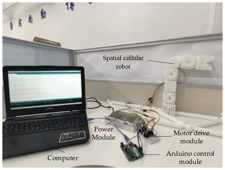
The space on-orbit cell assembly robot consists of multiple cell modules, each of which is controlled by a separate motor. The ground experiment platform assembled by robot truss is mainly composed of computer and relay unit. As shown in Fig. 13, the computer mainly carries out input, storage and communication of motor control variables. The relay unit is composed of 12 V power module, Arduino control module and motor drive module TMC2208. It mainly receives the drive control instructions issued by the computer, provides power for the motor in the revolute joint module, and drives the motor, so as to achieve specific movements of the robot.
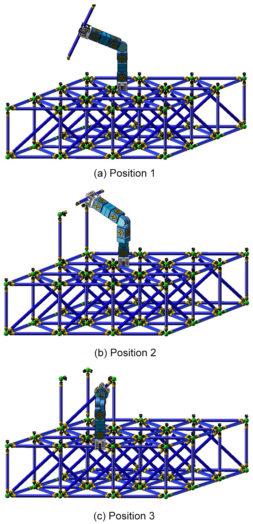
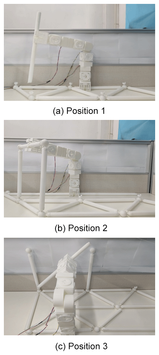
The on-orbit operation and assembly of the robot after it arrives at the designated position are simulated by the ground experimental platform. The ground equivalent experiment proves that the Spatial cellular robot can complete the truss assembly in three different positions. The special structure of the truss ball head has a certain guiding effect, which keeps the deviation of the experiment within the allowable range, so it can successfully complete the truss assembly task. The theoretical and experimental processes are shown in Figs. 14 and 15.
5.1 Kinematics simulation of robot based on ADAMS
5.1.1 Selection of simulation model parameters of space cell robot
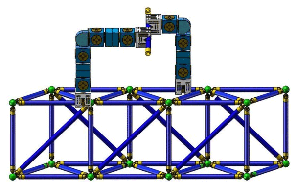
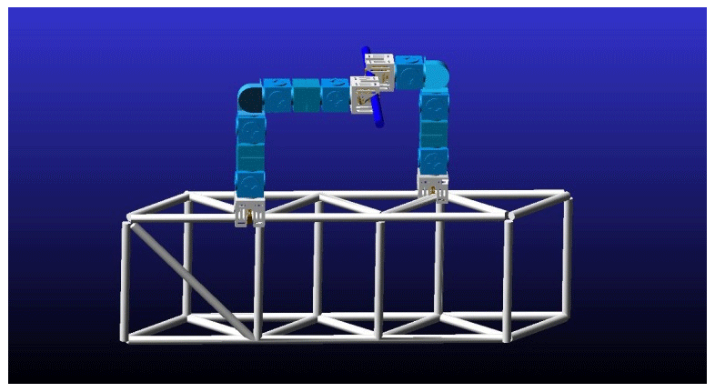
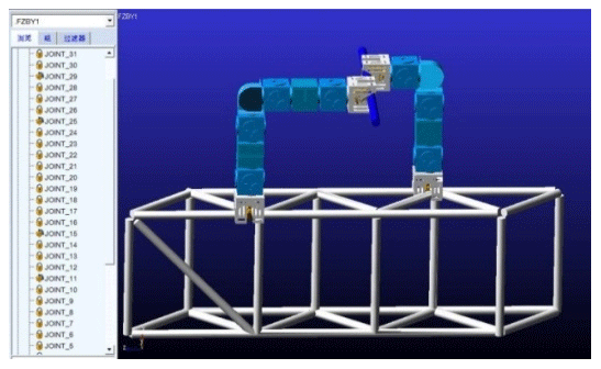
In order to verify the reliability and rationality of on orbit assembly process of space cell robot, ADAMS virtual prototyping technology is used to simulate the dynamic characteristics of on orbit assembly. After the model is imported, the material properties of the component modules and truss members of the robot are defined. Under the condition of ensuring the mechanical properties, space cell robot should also meet the requirements of lightweight. Therefore, the truss and grab manipulator are defined as 45 steel, the shell of cell module is aluminum alloy, and the material of internal parts is 40Cr. The solid model and simplified model of robot truss assembly are shown in Figs. 16 and 17.
After the model import and material definition are completed, it is necessary to redefine the relationship between each component and create relevant motion pairs to constrain the components. As shown in Figs. 4–6, create a motion pair for each component of the model. The model creates 5 rotation pairs, 2 moving pairs, and the rest are fixed pairs. The motion pairs between the specific components are shown in Fig. 18.
When the space cell robot is assembling the truss on orbit, it mainly depends on the cooperative rotation of the rotating joint to adjust the specific position of the truss, so that the truss can be assembled accurately at the designated position. Therefore, it is necessary to drive the rotary joint in the robot configuration. According to the design requirements, the 360∘ rotation joint and 180∘ rotation joint of the space truss on orbit assembly robot rotate 30∘ s−1, that is, the rotation angular velocity is 5π∕3 rad s−1. In order to make the robot rotate smoothly in the process of kinematics simulation, STEP function is used to drive the robot's rotating joint to move. The formula of STEP function is:
In the formula, X represents the independent variable, X0 represents the start value of the step function of the independent variable, X1 represents the end value of the step function of the independent variable, H0 represents the initial value of the step function, and H1 represents the end value of the step function.
According to the motion process of the transfer robot and the assembly robot, the 360∘ rotation joint module of the transfer robot, the second rotation joint module and the 180∘ rotation joint module of the assembly robot are driven and set, respectively, as motion1, motion2 and motion3. Motion1 mainly drives the transfer robot to make turning motion and transfer the truss rod to the assembly robot. Motion2 mainly drives the assembly robot to rotate the end clamping claw and adjust the assembly direction of truss bar. Motion3 mainly drives the assembly robot to move up and down the end clamping claw, so that the truss rod can be assembled in the exact position of the space truss. Step drive settings for specific joints are shown in Table 5 below.
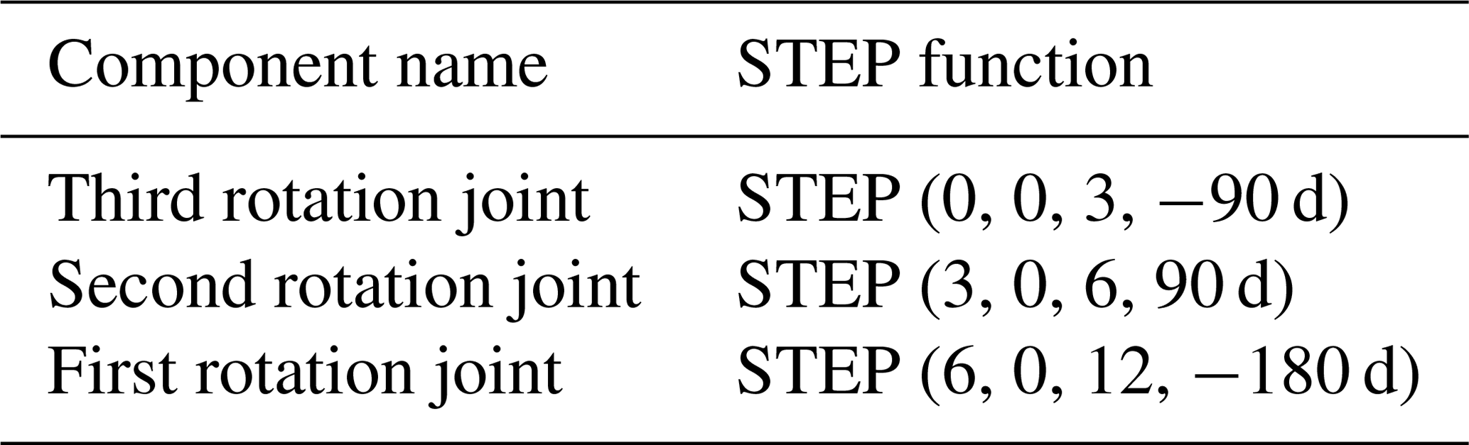
It can be seen from Tables 3–4 that the end gripper of the transfer robot is turned 90∘ within 0–3 s and separated from the truss rod. In 3–6 s, the end claw of the robot is rotated 90∘ to adjust the space position of the truss. In 6–12 s, the 180∘ rotating joint of the robot is rotated 180∘ so that the truss rod after adjusting the position can be installed on the truss accurately.
5.2 Simulation results and analysis of robot motion
By establishing kinematic model, defining material properties, imposing constraints and setting joint driving parameters for space truss on orbit assembly robot, the overall process of transfer robot and assembly robot collaborative truss assembly is simulated in ADAMS, and the cell unit module of the assembly robot is obtained under the condition of relevant constraints and driving, each joint drives the truss rod Change curve of position, speed, acceleration, etc. Because the whole truss assembly process is completed in space, the influence of gravity is ignored in the simulation process. Taking the assembly robot as the research object, the simulation results are analyzed and processed to verify the rationality of the on orbit assembly movement of the space truss of the assembly robot.
5.2.1 Simulation analysis of robot rotation
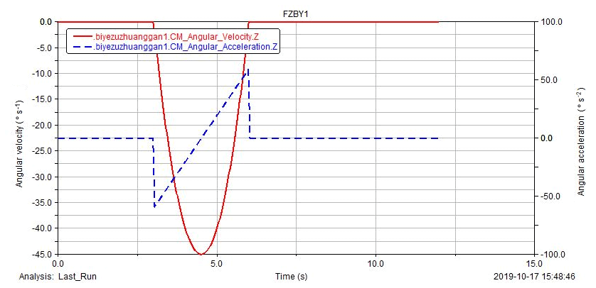
When assembling space trusses on orbit, the trusses assembly accuracy is determined by the trajectories of trusses clamped by the end claws. The purpose of the rotation movement of the assembly robot is to adjust the spatial position of the truss bar before assembly, and take the center point of the assembly truss bar as the marker point. Through the kinematic analysis of the truss bar clamped by the end claw of the assembly robot, the change curve of angular velocity and angular acceleration representing the rotation movement of the assembly robot is obtained, as shown in Fig. 19.
It can be seen from Figs. 4–7 that in the 3rd s, the truss rod starts to rotate along the z-axis direction driven by the second rotating joint of the assembly robot, and in the 6th s, the truss rod is adjusted to the corresponding space position, and in the 4th 5 s, the angular velocity reaches the maximum. From the result curve in the figure, it can be seen that if the curve of angular velocity and angular acceleration changes synchronously, the rotation of the truss rod is stable and in line with the motion law.
5.2.2 simulation analysis of robot assembly motion
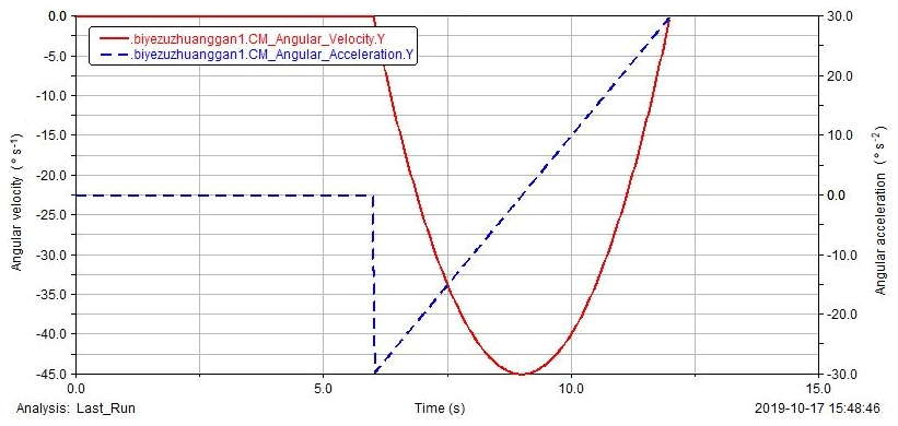
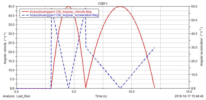
Robot assembly motion determines the accuracy of truss assembly, which is an important part of space truss on orbit assembly. The simulation analysis of robot assembly motion is the same as that described in Sect. 5.2.1. Take the center point of assembly truss as the marker point, through the kinematic analysis of truss rod clamped by the end claw of assembly robot, the change curve of angular velocity and angular acceleration representing assembly motion of assembly robot is obtained, as shown in Fig. 20.
It can be seen from Fig. 20 that the truss rod starts to rotate along the y-axis direction driven by the 180∘ rotating joint of the assembly robot in the 6th s, and it is assembled on the designated position of the truss in the 12th s, and the angular velocity reaches the maximum in the 9th s. It can be seen from the result curve in the figure that the curve of angular velocity and angular acceleration changes synchronously, and the assembly process of truss rod is stable, which conforms to the motion law of truss rod assembly.
5.2.3 overall motion simulation analysis of robot truss assembly
Through the analysis of the simulation results of the rotation and assembly motion of the space truss on orbit assembly robot by Adams, the change curves of the overall angular velocity and angular acceleration of the end claw grabbing truss rod movement and the change curves of the truss rod displacement and velocity are obtained, and the results are analyzed. The curve of angular velocity and acceleration of robot truss assembly is shown in Fig. 21.
It can be seen from Fig. 21 that the assembly robot is in standby state within 0–3 s. When the transfer robot completely disengages from the truss rod within 3∘ S, the assembly robot starts to move. In the third second, the truss rod rotates along the z-axis direction, in the sixth second, it rotates to the corresponding position, and there is no movement in other directions. In the 6th s, the truss rod rotates along the y-axis direction, in the 12th s, the truss rod reaches the designated position of the truss for assembly, and there is no movement in other directions.
From the result curve in Fig. 21, it can be seen that the overall motion of the robot truss assembly only includes the periodic rotation of the z-axis and x-axis, and the curves of the angular velocity and the angular acceleration change smoothly and the curves are synchronous. Therefore, the overall motion process of the robot truss assembly is stable and in line with the motion law.
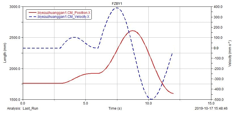
The assembly displacement and velocity curve of the robot truss is shown in Fig. 22. In 0–3∘ S, the truss is in standby state, and in 3–6 s, the truss is driven by the second rotating joint of the assembly robot to rotate. The maximum speed is reached at 4.5 s and the center point of the truss changes along the x-axis. In 6–12 s, the assembly robot starts to rotate through 180∘ rotation joint, and the truss rod is assembled to the designated position of the space truss. At this time, the center point of the truss rod changes in the x-axis direction with the rotation of the joint. In the 12th s, reach the exact assembly position and complete the truss installation.
From the result curve in Fig. 22, it can be seen that the displacement and speed of robot truss assembly change smoothly. In the 12th second, the truss rod reaches the assembly position accurately and the speed is reduced to 0, which avoids the collision during truss assembly and conforms to the robot assembly motion law.
Aiming at the problem of orbital truss path optimization for Spatial cellular robots, the triangular truss structure is taken as the research object, the shortest path length the optimization target, the obstacle avoidance rule is taken as the constraint condition, and the optimization algorithm is used to realize the collision avoidance of the space truss route plan.
- a.
This paper adopts a hierarchical search strategy to reduce the blind search in the early stage of ant colony by limiting the searchable area and improve the search efficiency. We propose a multivariate heuristic function with dynamic angle to make the improved algorithm have good convergence characteristics. The gravitational search operation is used to transform the optimal solution of the truss node into the initial value of the pheromone in the ant colony algorithm, which solves the problem that the prior averaging of the pheromone is easy to fall into the local optimum, and improves the search speed.
- b.
The truss on-orbit path planning is divided into two stages: pre-processing and path search. The pre-processing stage divides the area space by grid method, and imports the truss model into the Matlab environment to store the nodes in the free space. The path search innovation uses the gravity search-optimized ant colony fusion algorithm to simulate the spatial path. Compared with the improvement, the planning time is reduced by 7.592 s and the path is shortened by 272.079 mm. The results show that the algorithm is effective, simple and efficient. This method also applies to the path planning problem of other configuration trusses.
This paper focuses on the path planning of space cellular robots in triangular truss. In the future, it will focus on the Cooperative Path Planning of various space cellular robots and the dynamic obstacle avoidance in the process of robot movement. In the truss working environment, how to make the robot more flexible to avoid obstacles in the actual working environment is also the main research direction in the future. In the aspect of path planning, it will further improve the path planning algorithm, integrate a variety of algorithms, and absorb the advantages of each algorithm to solve the problem of multi robot cooperative path planning. Coordinate and cooperate according to the requirements of on orbit tasks and complete the problem of robot formation. In the future, the research of space on orbit multi robot cooperative operation is of great significance to the development of aerospace.
All the data in this paper are obtained by experimental measurement. The calculation results of the data are obtained through the experimental theoretical design.
The supplement related to this article is available online at: https://doi.org/10.5194/ms-11-233-2020-supplement.
This research work is a joint effort of the whole team. YD and ZL determined the research direction and experimental methods and wrote the whole paper. ZL completed the algorithm design and improvement. YQ assisted in the whole experimental verification. HZ assisted in the experimental simulation. YG checked the written language, and BY reviewed the paper.
The authors declare that they have no conflict of interest.
The authors wish to thank the support of the Natural Science Foundation of Heilongjiang Province of China (grant no. LH2019E062).
This research has been supported by the National Natural Science Foundation of China (grant no. E51505109), the University Nursing Programfor Young Scholars with Creative Talents in Heilongjiang Province (grant no. UNPYSCT-2017077), the Fundamental Research Foundation for Universities of Heilongjiang Province (grant no. LGYC2018JC040), the China Postdoctoral Science Foundation (grant no. 2016M591539), the Heilongjiang Postdoctoral Science Foundation (grant no. LBH-Z15102), and the Natural Science Foundation of Heilongjiang Province of China (grant no. LH2019E062).
This paper was edited by Daniel Condurache and reviewed by two anonymous referees.
Alberto, V., Dmitriy, S., and Luis, M.: Robotic active information gathering for spatial field reconstruction with rapidly-exploring random trees and online learning of gaussian processes, Sensors, 19, 1016–1040, https://doi.org/10.3390/s19051016, 2019.
Anh, V. L., Veerajagadheswar, P., and Vinu, S.: modified A-Star algorithm for efficient coverage path planning in tetris inspired self-reconfigurable robot with integrated laser sensor, Sensors, 18, 2585–2612, https://doi.org/10.3390/s18082585, 2018.
Chung, W. K. and Xu, Y. S.: Minimum energy demand locomotion on space station, J. Robotic. Syst., 15, 36–51, https://doi.org/10.1155/2013/723535, 2013.
Gu, S. C., Zhu, H. F., and Li, H.: Optimal collision-free grip planning for biped climbing robots in complex truss environment, Appl. Sci., 8, 2533–2555, https://doi.org/10.3390/app8122533, 2018.
Hou, F. L. and Shen, W. M.: Graph-based optimal reconfiguration planning for self-reconfigurable robots, Robotics and autonomous systems, Robotics and Autonomous Systems, 62, 1047–1059, https://doi.org/10.1016/j.robot.2013.06.014, 2014.
Jiang, M., Wang, F., Ge, Y., and Sun, L. L.: Research on path planning of mobile robot based on improved ant colony algorithm, Chin. J. Sci. Inst., 40, 113–122, https://doi.org/10.19650/j.cnki.cjsi.J1804429, 2019.
Liang, J. H. and Lee, C. H.: Efficient collision-free path-planning of multiple mobile robots system using efficient artificial bee colony algorithm, Adv. Eng. Softw., 79, 47–56, https://doi.org/10.1016/j.advengsoft.2014.09.006, 2015.
Liu, Y. J., Yu, W. J., Ye, Z. P., and Wang, C. G.: Path planning for self-reconfigurable modular robots: a survey (in Chinese), Sci. Sin. Inform., 48, 143–176, https://doi.org/10.1360/N112017-00154, 2018.
Qi, R. L., Zhou, W. J., Liu, J. G., Zhang, W., and Lei, X.: Obstacle avoidance trajectory planning for gaussian motion of robot based on probability theory, J. Mech. Eng., 53, 92–100, https://doi.org/10.3901/JME.2017.05.093, 2017.
Su, J. B. and Xie, W. L.: Motion planning and coordination for robot systems based on representation space, transactions on systems, IEEE Trans. Syst. Man Cyb., 41, 248–260, https://doi.org/10.1109/TSMCB.2010.2051025, 2011.
Sun, J. B., Liu, G. L., and Tian, G. H.: Smart obstacle avoidance using a danger index for a dynamic environment, Appl. Sci., 9, 1589–1603, https://doi.org/10.3390/app9081589, 2019.
Tan, W. S., Wei, H. X., and Yang, B.: SambotII: a new self-assembly modular robot platform based on sambot, Appl. Sci., 8, 1719–1739, https://doi.org/10.3390/app8101719, 2018.
Wang, L. F., Kan, J. M., Guo, J., and Wang, C.: 3D Path planning for the ground robot with improved ant colony optimization, Sensors, 19, 815–836, https://doi.org/10.3390/s19040815, 2019.
Wang, X. W., Xue, L. K., Yan, Y. X., and Gu, X. S.: Welding robot collision-free path optimization, Appl. Sci., 7, 89–100, https://doi.org/10.3390/app7020089, 2017.
Wei, H. X. and Li, H. Y.: A Swarm Self-assembly Modular Robot for Space Exploration, Spac. Eng., 20, 72–79, 2011.
Wei, H. X. and Wang, T. M.: Configuration analysis and self-assembly control for modular swarm robots, J. Mech. Eng., 7, 100–109, https://doi.org/10.3901/JME.2010.13.100, 2010.
Wei, K. and Ren, B. Y.: A method on dynamic path planning for robotic manipulator autonomous obstacle avoidance based on an improved RRT algorithm, Sensors, 18, 571–586, https://doi.org/10.3390/s18020571, 2018.
Zhu, H. F., Gu, S. C., and Li, H.: Transition analysis and its application to global path determination for a biped climbing robot, Appl. Sci., 8, 122–143, https://doi.org/10.3390/app8010122, 2018.
Zhao, J. D. and Han, J. G.: Gait Planning and Study of Climbing Robot with Three Branches for Space Station Truss, Manned. Spaceflight., 24, 14–20, https://doi.org/10.16329/j.cnki.zrht.2018.01.003, 2018.
- Abstract
- Introduction
- Environment modeling and analysis
- Fusion optimization algorithm based on truss path planning
- Simulation results and analysis of path planning
- In-orbit assembly simulation experiment
- Conclusions
- Data availability
- Author contributions
- Competing interests
- Acknowledgements
- Financial support
- Review statement
- References
- Supplement