the Creative Commons Attribution 4.0 License.
the Creative Commons Attribution 4.0 License.
 | 11 Jun 2019
Influence of grinding wheel parameters on the meshing performance of toroidal surface enveloping conical worm drive
Chongfei Huai
Yaping Zhao
A new type of toroidal surface enveloping conical worm gearing is proposed in our recent work (Chongfei and Yaping, 2019b). According to its forming principle, the geometrical shape of the generating surface has an important influence on the geometry characteristic of the enveloping worm pair. To explore the reasonable principles for selecting the geometrical parameters of the grinding wheel, some numerical study examples are performed. In this process, the methods for the tooth crest width are developed. Simple strategies for estimating the risk of the worm tooth surface being located in the invalid area and the risk of the curvature interference on the tooth surface are proposed. The numerical result shows that increasing the radius of the toroidal-generating surface and the nominal pressure angle of the grinding wheel are beneficial to improve the engagement behavior of the conical worm pair, but the tooth crest sharpening of the conical worm may happen if they are too large. For the nominal radius of the grinding wheel, it has a negligible effect on the meshing characteristics of this worm set. In addition, the selection principle of the parameters is also suggested.
- Article
(4945 KB) - Full-text XML
- BibTeX
- EndNote


The classical conical worm drive is composed of an Archimedean conical worm and a conical face gear (Litvin, 1997). In line with its forming mechanism, the screw helicoid of the Archimedean conical worm is a ruled surface and is arduous to grind precisely in line with the forming principle (Bohle, 1955; Nelson, 1961). Apparently, it is not conducive to the hardening of the tooth surface after it is shaped, and the further enhancement of the meshing behavior of the conical worm drive is thus limited (Yaping and Xiangwei, 2018).
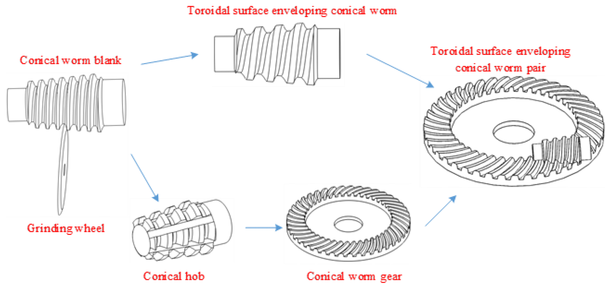
To overcome the shortcoming mentioned above, a new type of toroidal surface enveloping conical worm gearing is suggested in our recent work (Chongfei and Yaping, 2019b). As shown in Fig. 1, the helical surface of this new type of conical worm is ground by a grinding wheel with the toroidal-generating surface. Meanwhile, the coupled worm wheel is enveloped by a taper hob whose working surface is consistent with that of the obtained conical worm.
From the perspective of forming principles, the shape of the generating torus has an important influence on the geometry of the tooth surfaces of this new type of enveloping conical worm drive. As is well known, the shapes of the two tooth surfaces in the mesh usually have a very important influence on the meshing quality of the gear (Litvin, 2004). Besides, there is no relevant experience for this new type of conical worm drive. Therefore, it is indispensable to study the geometry of the grinding wheel for the sake of improving the meshing quality of the toroidal surface enveloping conical worm gearing and providing a reasonable principle of parameter selection for the production.
In this paper, a method to calculate the worm tooth crest width without solving the nonlinear equations is suggested, and new strategies for estimating the risk of the worm tooth surface being located in the invalid area and the risk of the curvature interference on the tooth surface are proposed. Based on this, the effects of geometrical parameters of the abrasion wheel, including the nominal radius of the abrasion wheel, the radius of the toroidal-generating surface, and the pressure angle of the grinding wheel, on the meshing performance of the toroidal surface enveloping conical worm drive are investigated.
For the numerical simulation study, some relevant theoretical background needs to be briefly introduced in this section.

2.1 Tooth surface equations
As drawn in Fig. 2, a moveable frame connected with the grinding wheel is established. For convenience, the basal vector id is parallel to the end plane of the grinding wheel and passes through the point B, and the unit vector kd is along the shaft axis of the abrasion wheel. Then, the vector jd can be determined by the cross product of id and kd.
The generating torus on the abrasion wheel intersects with the shaft section of the abrasion wheel along the arc. The projection distance of the points A and C in the radial direction of the grinding wheel is set as hf, which is the dedendum of the toroidal surface enveloping conical worm. In σd, the abscissa and ordinate of the center point of the arc, Og, can be severally represented as (−ρcos α, Rn−ρsin α). Therein, Rn denotes the distance between the original point Od and the point C and can be called the nominal radius of the abrasion wheel, ρ represents the radius of the arc, and α signifies the closed angle between the tangent line at the point C and the end plane of the grinding wheel, which can be called the pressure angle of the grinding-wheel-generating torus. Based on the above, the arc will be determined exclusively when the values of Rn, ρ, and α are given.
In accordance with the geometry site displayed in Fig. 2, the vector equation of the toroidal-generating surface, Σd, may be obtained in σd as
where , yd=[ρ , and . Therein, the angles θ and ϕ are the two curvilinear coordinate parameters of Σd. In theory, any point on Σd can be uniquely determined by a set of θ and ϕ.
By definition (Wardle, 2008), the unit normal vector of Σd in σd can be procured as
where nx=sin ϕcos θ, ny=sin ϕsin θ, and nz=cos ϕ.
As illustrated in the reference (Chongfei and Yaping, 2019b), during the process of grinding the work blank, the vector equation and the unit normal vector of Σd can be expressed in the moving frame σo1 as
where , , nox =nxcos (Sπ −γ), noy=sin ϕ sin θ, and .
The coefficient S is used to distinguish the two sides of the tooth of the conical worm. When S=0, Eq. (3) expresses the i flank of the conical worm. When S=1, Eq. (3) indicates the e flank of the conical worm.
Next, the tooth equation of the worm helical surface, , can be acquired in σ1 as
where , , and .
By the literature (Chongfei and Yaping, 2019b), the relative velocity vector of the abrasion wheel and the worm roughcast in σo1 can be calculated by
where , , and .
Based on Eqs. (4) and (6), the meshing function of the abrasion wheel and the conical worm roughcast in the process of the grinding engagement can be yielded as
where and .
In the process of mesh, the equation of the surface family, , and its unit normal vector can be deduced in as follows:
where , , , and .
In line with the method elaborated in the literature (Chongfei and Yaping, 2019b), the relative speed of the worm pair can be obtained in σo1 as
where , , and . Herein, Lw is the actual working length of the conical worm and zp is the axial mounting position of the conical worm.
Based on Eqs. (9) and (10), the mesh function of the toroidal surface enveloping conical worm gearing can be worked out as
where , , and C=nozVz.
Via the coordinate transformations, the equation of the conical worm wheel tooth surface can be acquired in σ2 as
where and .
Correspondingly, when S=0, Eq. (12) indicates the convexity ( of the worm wheel. When S=1, Eq. (12) expresses the concavity ( of the worm wheel.
2.2 Meshing characteristic parameters
On the basis of the classical differential geometry (Wardle, 2008), the coefficients of the first and second fundamental forms of Σd can be derived as
Owing to , the two principal curvatures along and can, respectively, be acquired as
The basal vectors g1 and g2 of the frame σM on Σd in σo1 can be obtained by the coordinate transformation as follows:
where , , cos (Sπ−γ), (Sπ −γ), , and sin (Sπ −γ).
Subsequently, the normal vector, Nd, of the line of contact in the grinding process can be worked out as
where and .
By definition (Litvin, 2004), the curvature interference limit function during the grinding mesh of the enveloping conical worm can be written as
On the basis of Eqs. (16) and (17), the two base vectors and of the moving orthogonal frame can be obtained as
and then the normal vector of the instantaneous contact line in the meshing process of the worm pair can be gained in σM as
where and .
By definition (Xuezhu, 1989), the meshing limit function of the worm pair can be represented as
On the basis of Eqs. (10), (21), (22), and (23), the curvature interference limit function of the conical worm pair can be acquired as
Based on the above calculated results, the induced normal curvature and the sliding angle θvt at the meshing point of the conical worm gearing can be derived as
Generally speaking, the smaller the value of , the better the local meshing characteristics (Johnson, 1985; Xiaolu and Zhongkai, 1992). The closer the value of θvt approaches 90∘, the better the forming condition of the EHL oil film is there (Xuezhu, 1989; Yaping and Xiangwei, 2018a; Chongfei, 2019).
3.1 Qualitative analysis of variation of parameters ρ, α and Rn
The geometric representation to display the effects of the radius of the generating toroidal surface on the worm tooth shape is given in Fig. 3a. Therein, . It is obvious that when ρ increases, the tooth crest width and tooth root width of the conical worm both decrease. In particular, ρlim denotes the minimum limiting value of the radius of the generating toroidal surface, and it can be derived as . This means that if the radius of the generating toroidal surface is less than ρlim when the parameters Rn and α are constant, the whole helicoid of the conical worm blank will be ground incompletely.

Figure 3Geometric representation of the variation of the grinding wheel geometry parameters.
Figure 3b is the geometric representation of the effects of the nominal pressure angle of the abrasion wheel on the worm tooth shape. Therein, . It indicates that the tooth crest width is decreasing while the tooth root width is increasing with the enlargement of α. In particular, αlim represents the limit value of the nominal pressure angle of the grinding wheel, and it can be derived as . It means that if the nominal pressure angle is less than αlim when the parameters Rn and ρ are constant, the helicoid of the conical worm blank cannot be ground completely.
As shown in Fig. 3c, it can be found that the variation of the nominal radius of the grinding wheel, Rn, has no effect on the geometrical shape of the conical worm tooth. But the value of Rn should be bigger than that of , where is the minimum limiting value of the nominal radius of the grinding wheel and .
3.2 Basic parameters
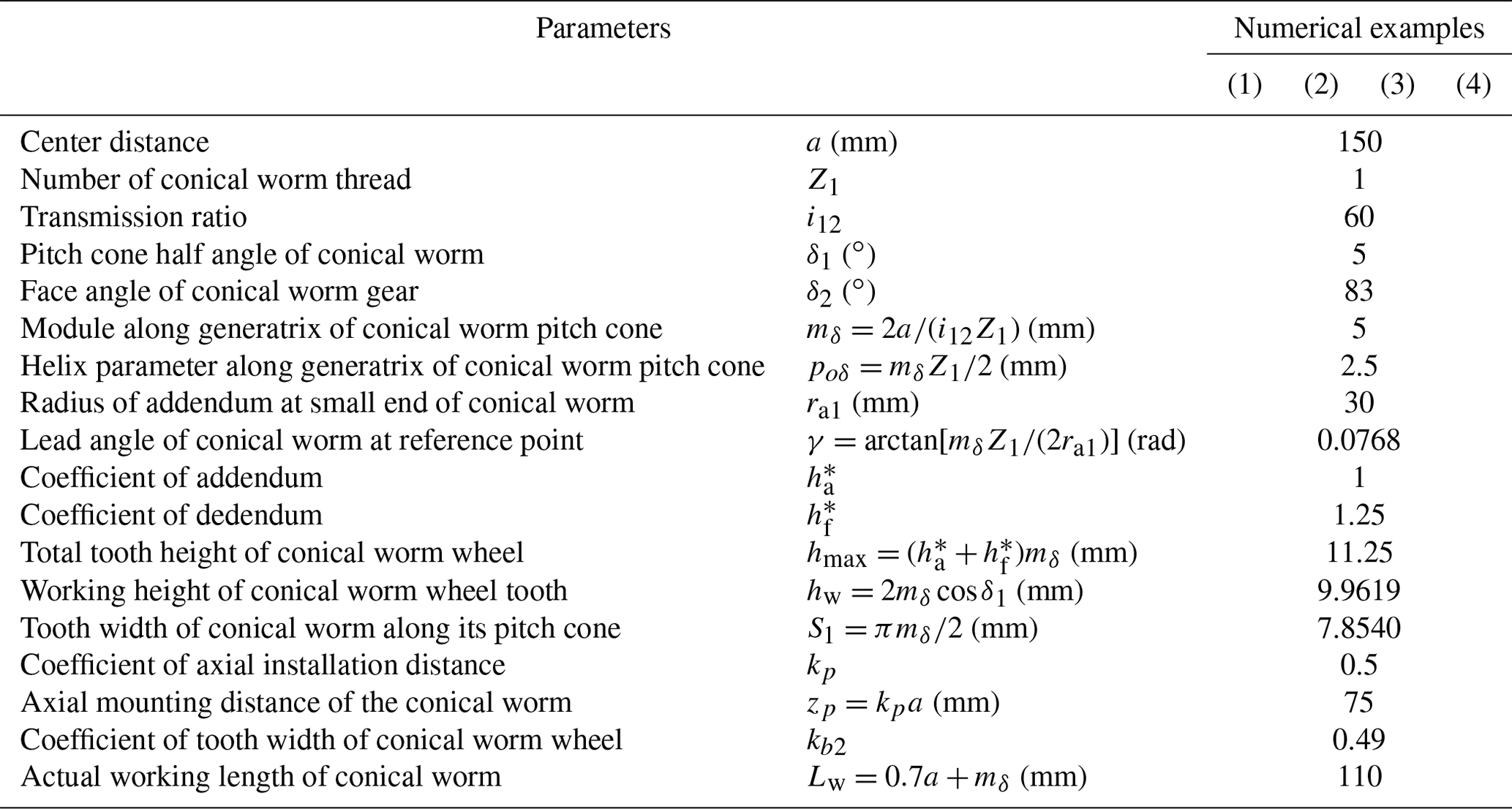
On the basis of the presented theoretical background in Sect. 2, four representative numerical examples labeled (1), (2), (3) and (4), respectively, are provided to investigate the influence of grinding wheel parameters on the meshing characteristics of the toroidal surface enveloping conical worm drive. Among them, Examples (1) and (4) are used to research the influence of the nominal pressure angle of the abrasion wheel, Examples (2) and (4) are used to study the effects of the nominal radius of the grinding wheel, and Examples (3) and (4) are used to research the influence of the radius of the toroidal-generating surface. The main parameters, which include the technical parameters of the toroidal surface enveloping conical worm pairs and the geometrical parameters of the abrasion wheel, are listed in Tables 1 and 2. In general, coefficients kp and kb2 should be selected as small as possible to reduce the size of the worm gear set.
Table 1Parameters of the conical worm drive in each numerical example.
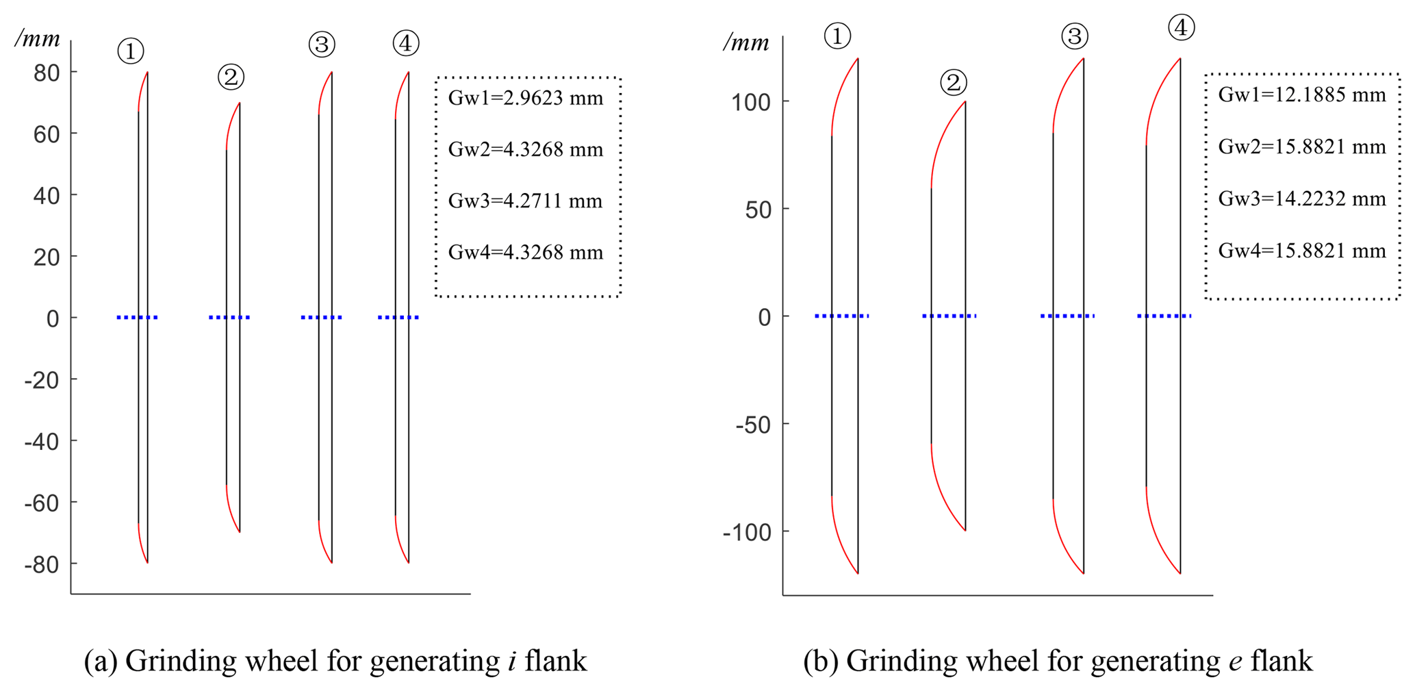
According to the geometric parameters provided in these tables, the skeleton maps of the grinding wheel in its shaft section are drawn in Fig. 4. In the picture, the symbol Gw represents the thickness of the grinding wheel. It indicates that increasing the parameters α and ρ results in an increase in the thickness of the abrasion wheel, while the increasing of the nominal radius of the grinding wheel has no influence on the thickness of the grinding wheel.
3.3 Influence of the grinding wheel parameters on tooth crest width of the toroidal surface enveloping conical worm
Generally speaking, the tooth crest width of the worm can be calculated by solving a series of nonlinear equations (Xuezhu, 1987). But objectively speaking, solving nonlinear equations is usually a cumbersome process. In this work, a method is used without solving the nonlinear equations and just according to the geometric relationship between the grinding wheels corresponding to the two sides of the conical worm tooth. According to the geometric positional relationship shown in Fig. 5, the tooth crest width of the toroidal surface enveloping conical worm, sb1, can be derived as
where , , , , , and .
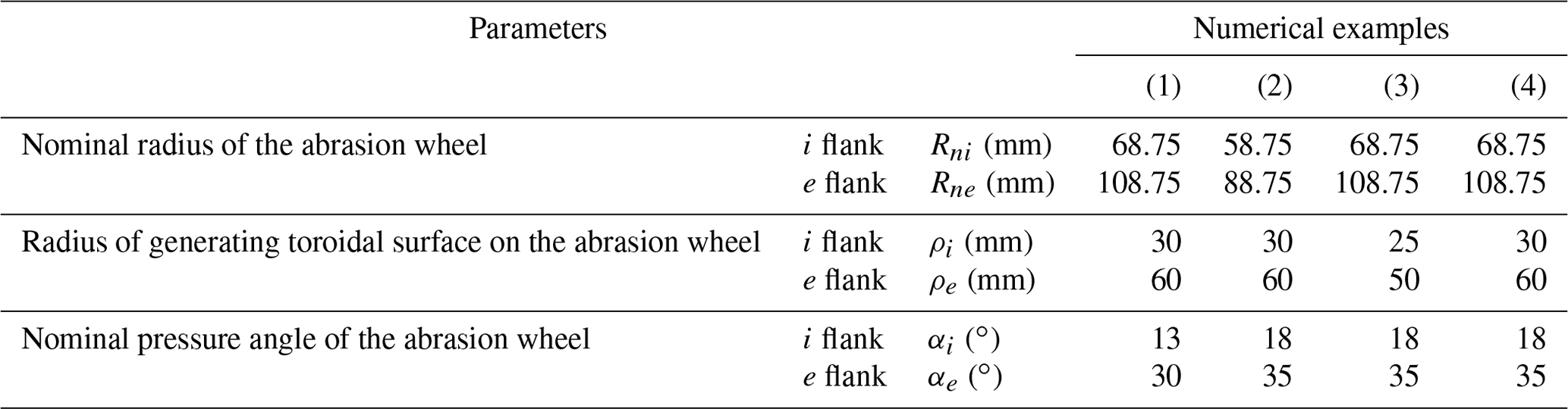
Table 2Geometric parameters of the abrasion wheel in each numerical example.

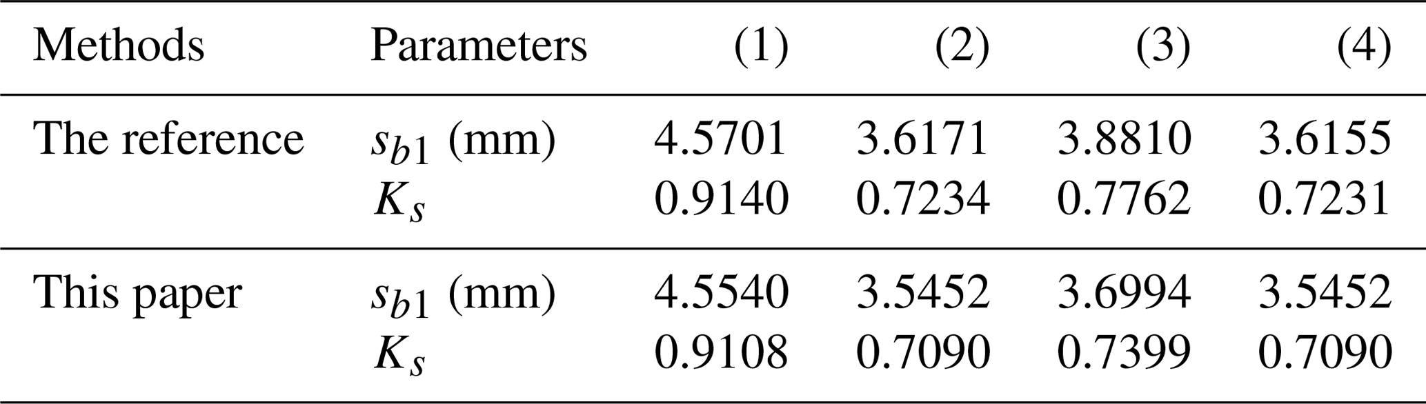
The values of sb1 and Ks calculated by the method illustrated in the reference (Chongfei and Yaping, 2019b) and by the method suggested above are all provided in Table 3. It is easy to know that the grinding wheel radius has a negligible influence on the tooth crest width of the toroidal surface enveloping conical worm. However, reducing the value of ρ and α can increase the crest thickness of the conical worm tooth. Obviously, these laws of influence are consistent with the trends reflected in Fig. 3. Besides, the error in the value of sb1 calculated by the two methods is minor, and it means that Eq. (26) is effective. The reason for the error is that the profile curves of the worm tooth and the grinding-wheel-generating surface are close but not identical in the axial section.
Table 3Numerical results of tooth profile parameters in the examples by different methods.
3.4 Effects of grinding wheel parameters on the distribution of the meshing limit line
In line with the meshing theory (Litvin, 2004; Xuezhu, 1989), the meshing limit line will divide the whole helical surface of the worm into an active zone and an inactive zone if it exists on the tooth surface. For the conical worm pair, the whole worm tooth surface has the risk of being in the inactive zone since the conical worm is offset to one side of the mating worm wheel. Therefore, it is of great significance to discover the influence of process parameters on the distribution of the meshing limit line.
Based on Eqs. (5), (7), (11), and (22), the meshing limit line on the tooth surface of the conical worm can be determined by the following equations:
Combining the third and fourth equations of Eq. (26) by eliminating the angle φ1 yields
In general, giving the abscissa of the points on the meshing limit line and based on Eq. (27), the parameters of these points can be acquired. Based on this, the meshing limit line can thus be determined, and then we can judge whether the meshing zone of the worm gearing is effective or not, while in fact the question of whether the conjugate area is effective actually is whether the angle φ1 has a real solution in this zone. If the real solution of φ1 exists, the meshing zone is valid; otherwise, it is invalid.
By letting Φ12=0, the analytical solution of the angle φ1 can be obtained as
in particular, φ0 is an aided angle, and it can be ascertained by and .
From Eq. (28), it can be found that the necessary condition for φ1 to have a real solution is . As is well known, on the meshing limit line, (Yaping et al., 2010, 2011, 2017). Therefore, the value of at any meshing point in the valid engagement zone should be in the interval of 0 to 1. For the sake of simplicity, we can define the predictive coefficient , which can be used to predict whether the related inspection point is within the engagement zone and to assess the degree of risk of the meshing limit line entering the meshing zone. Concretely, the closer the value of kML at the inspection point is to 1, the closer the point is to the meshing limit line. If the value of kML at the related inspection point is greater than 1, it can be predicted that this point is in the invalid area and thus cannot participate in meshing. A large number of trial results indicates that the meshing limit line only appears on the e flank of the conical worm tooth surface and does not enter the i flank of the worm tooth surface. For brevity, only the values of kML at the inspection points along the addendum of the e flank of the conical worm tooth surface are provided in Table 4.
Table 4Values of kML at the inspection points on the e flank of the conical worm.

As we can see, the values of kML listed in Table 4 show that the point on the tooth crest at the small end of the conical worm is closer to the meshing limit line than the other points on the addendum of the conical worm. Comparing Examples (1) and (4), it can be found that the increase in the nominal pressure angle of the grinding wheel can help the meshing limit line to move away from the conical worm tooth surface. According to the values of kML at the inspection points in Example (2), it is obvious that the variation of the nominal radius of the grinding wheel has an almost negligible impact on the distribution of the meshing limit line. For Example (3), it indicates that the related inspection points are closer to the meshing limit line compared to Example (4), with the increasing of the radius of the generating torus.
3.5 Effects of grinding wheel parameters on the distribution of the curvature interference limit line
From the meshing theory (Litvin, 2004; Xuezhu, 1989), it can be known that the curvature interference limit line may cause the undercutting when it exists on the tooth surface.
In this section, the influence of process parameters on the distribution of the curvature interference limit line in the grinding engagement of the worm will be investigated. Since the helical surface of the conical worm is the enveloping surface of the abrasion-wheel-generating surface, the curvature interference (undercutting) may occur on the conical worm helicoid.
By definition, the value of Ψd should be equal to 0 if the curvature interference limit line exists. When the parameters of the inspection point are determined, we can estimate the distance between this point and this limit line based on the value of Ψd. The closer the value of Ψd is to 0, the closer the point is to this limit line and the higher the risk is of the undercutting occurring on the conical worm helicoid. Based on Eq. (19), the value of Ψd can be worked out. Since the curvature interference usually does not occur on the i flank, only the numerical results of Ψd at the inspection points on the addendum of the worm e flank are provided in Table 5.
Table 5Value of Ψd at the inspection points on the e flank of the conical worm

From Table 5, it is clear that the curvature interference limit line is closest to the small end and tooth crest of the conical worm; that is to say, the risk of tooth undercutting is highest in there. As reflected by the data in Examples (1) and (4), increasing the nominal pressure angle of the abrasion wheel can drive the curvature interference limit line away from the conical worm tooth surface: this means that the risk of undercutting on the tooth surface of the worm can be reduced. Comparing Examples (2) and (4), we can find that increasing the nominal radius of the abrasion wheel can reduce the risk of curvature interference. The values of Ψd at the inspection points in Example (3) indicate that reducing the radius of the generating toroidal surface will cause the curvature interference limit line to approach the tooth surface of the conical worm compared with that in Example (4).
3.6 Effects of grinding wheel parameters on global meshing performance
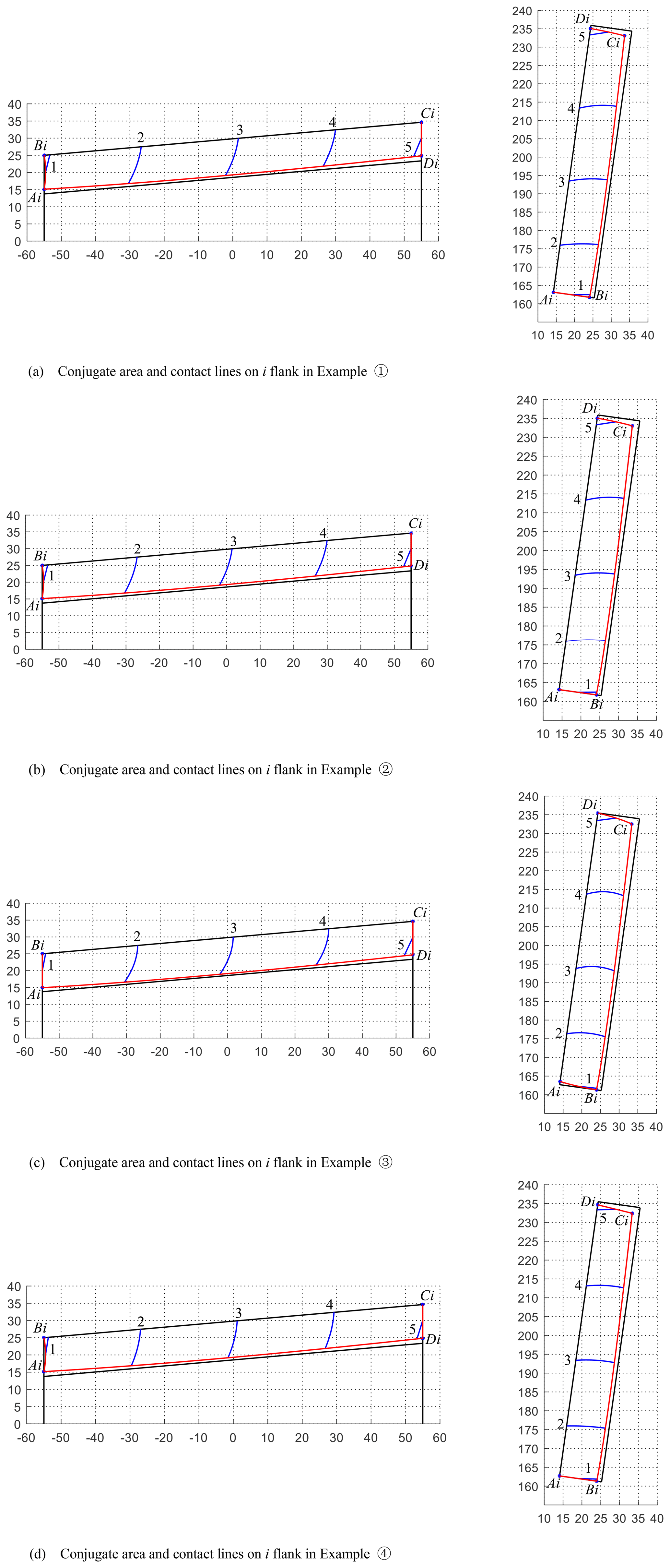
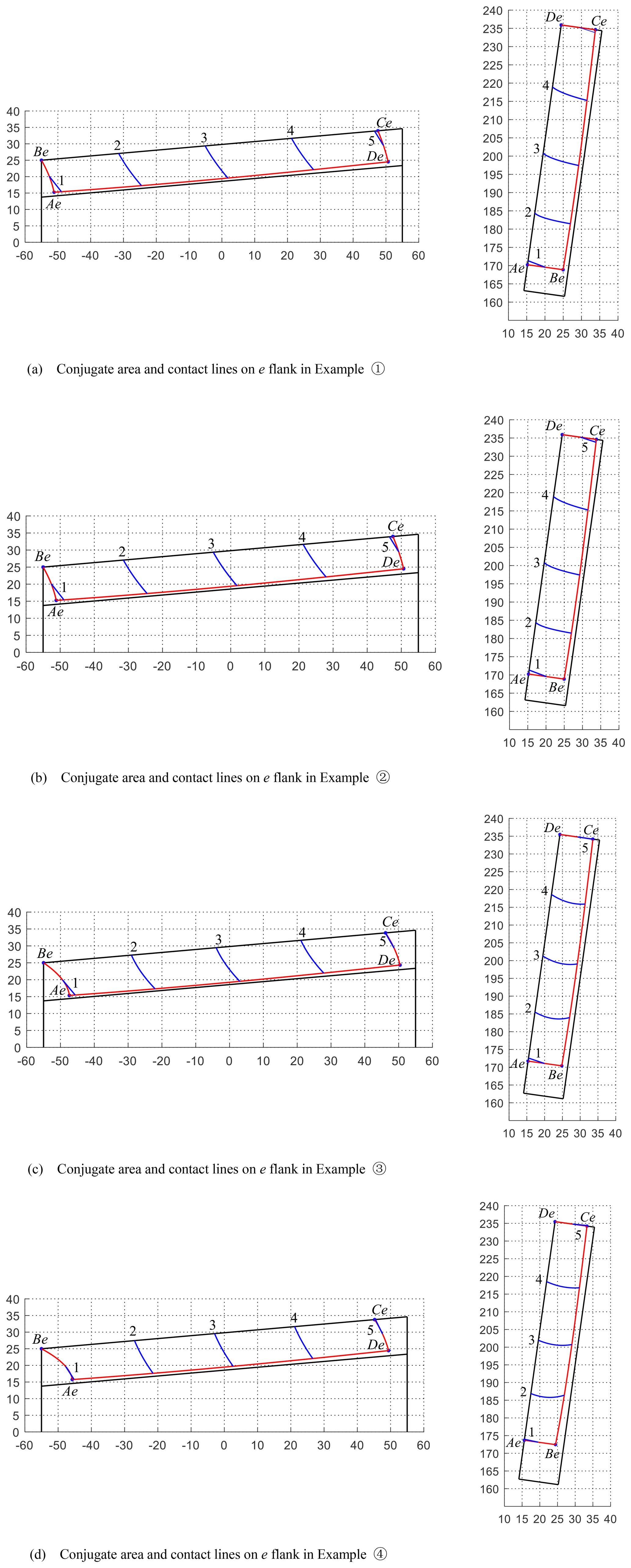
The meshing zones and the lines of contact on both the i flank and e flank in the numerical examples are displayed in Figs. 6 and 7, respectively. The meshing zones are tagged as AiBiCiDi and AeBeCeDe, and the instantaneous contact lines are numbered as 1, 2, 3, 4, and 5.
For Examples (1) and (3), their meshing areas on the i flank and e flank of the corresponding worm pairs are all reduced compared with Example (4); this phenomenon means that magnifying the parameters ρ and α can increase the global meshing behavior of the toroidal surface enveloping conical worm gearing. While the scale of the conjugate zones and the distribution of contact lines on both the i flank and e flank in Example (2) are severally similar to that in Example (4), it reflects that the vibration of the grinding wheel nominal radius Rn has an almost negligible effect on the global meshing quality of the worm drive.
3.7 Effects of process parameters on local meshing performance
To survey the influence of geometric parameters of a grinding wheel on the local meshing characteristic of conical worm gearing, six points on the tooth flank of a worm wheel are selected randomly as the inspection points. After ascertaining these points, the local meshing characteristic parameters, such as the induced principal curvature and the sliding angle θvt, can be calculated on the basis of Eq. (24). The line charts of the numerical variation of the two parameters are provided in Figs. 9 and 10.

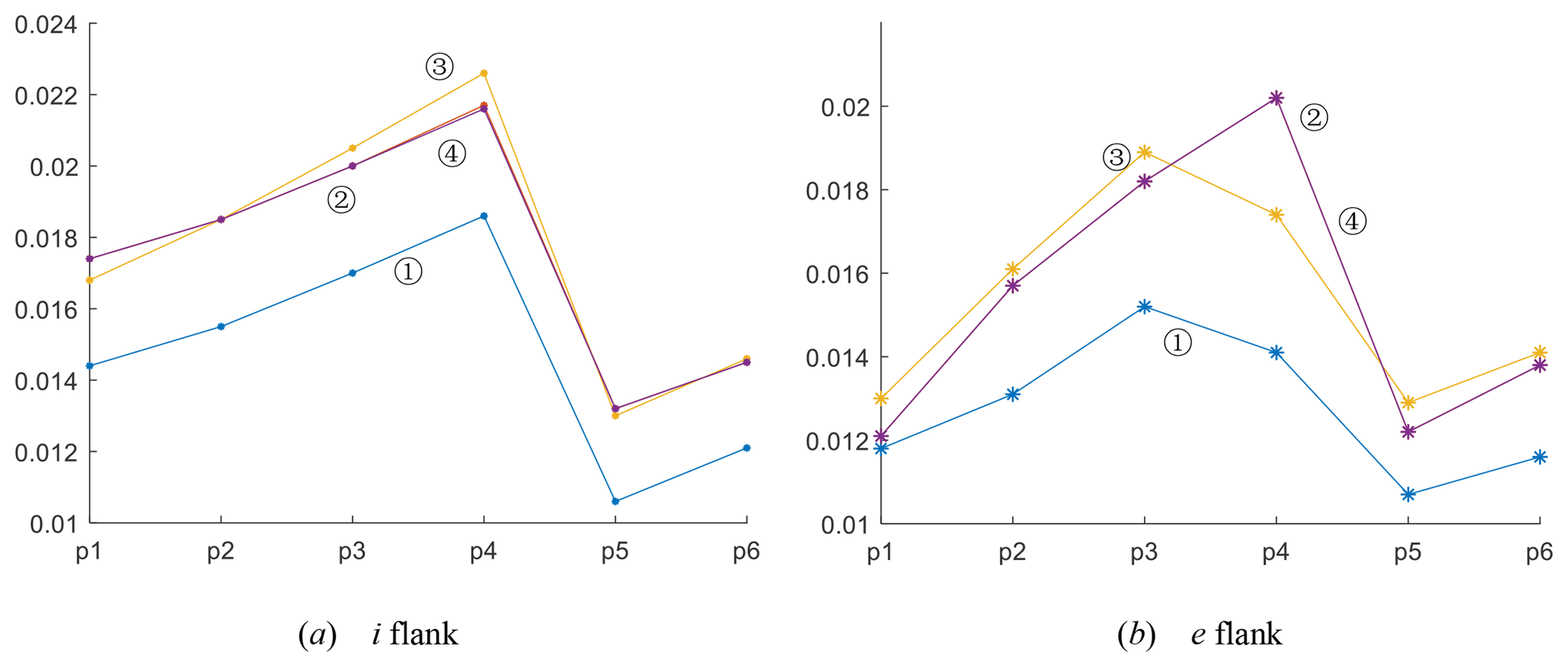

In line with the data in these tables, the values of and θvt, on both the i and e flanks of the worm pair, have not changed significantly with the variation of Rn. While the radius of the toroidal-generating surface, ρ, is increasing, the values of θvt will magnify at the inspection points, which will improve the lubrication performance of the worm gear to some extent. This rule is also applicable when the nominal pressure angle of the grinding wheel, α, is increasing.
The mathematical model is constructed for the meshing simulation of the toroidal surface enveloping conical worm gearing, whose conical worm helicoid is ground by an abrasion wheel with the toroidal-generating surface.
The qualitative analysis of the variation of grinding wheel parameters is performed. On the basis of the established mathematical model, the numerical simulations are implemented. In this process, the method to calculate the worm tooth crest width without solving the nonlinear equations is suggested. The simple strategies for estimating the risk of the worm tooth surface being located in the invalid area and the risk of the curvature interference on the tooth surface are proposed.
The results of the numerical examples study disclose the following.
-
The increase in the nominal pressure angle α of the abrasion wheel and the radius of generating surface ρ are helpful in reducing the risk of the worm surface being in the invalid zone and the curvature interference being on the worm helicoid. It is also helpful in improving the mesh behavior of the toroidal surface enveloping conical worm gearing. But the top thickness of the conical worm will be reduced with the increase in the two parameters. Therefore, the values of α and ρ should be limited in a certain scope. Based on a large number of trial results, is recommended for the i flank and for the e flank. Besides, the parameter ρ is suggested in the scope of 0.5 ra1 to 1.5 ra1.
-
Though the variation of the nominal radius of the grinding wheel Rn has almost no effects on the meshing performance of this worm drive, increasing its value can reduce the risk of curvature interference on the worm helicoid. However, in order to save the cost of manufacturing a grinding wheel, the parameter Rn should not be too large.
All the data used in this article can be made available upon reasonable request. Please contact the corresponding author (Yaping Zhao, zhyp_neu@163.com).
CH conducted theoretical calculation and example studies and wrote the manuscript under the guidance of YZ. YZ verified the results and supervised the whole work.
The authors declare that they have no conflict of interest.
The authors acknowledge the open fund of the key laboratory for metallurgical equipment and control of the Ministry of Education in Wuhan University of Science and Technology (2018B05) and the subsidy from the National Natural Science Foundation of China (51475083).
This research has been supported by the National Natural Science Foundation of China (grant no. 51475083), the Fundamental Research Funds for the Central Universities (grant no. N160304012), and the Chinese National Natural Science Foundation (grant no. U1708254).
This paper was edited by Bahman Azarhoushang and reviewed by two anonymous referees.
Bohle, F.: Conical worm Gears, Mach., 62, 155–161, 1955.
Chongfei, H. and Yaping, Z.: Variable height modification of TA worm drive, P. I. Mech. Eng. C-J. Mec., 233, 227–243, https://doi.org/10.1177/0954406218757269, 2019a.
Chongfei, H. and Yaping, Z.: Meshing theory and tooth profile geometry of toroidal surface enveloping conical worm drive, Mech. Mach. Theory, 134, 476–498, https://doi.org/10.1016/j.mechmachtheory.2019.01.006, 2019b.
Johnson, K. L.: Contact Mechanics, Cambridge University Press, UK, 1985.
Litvin, F. L.: Development of Gear Technology and Theory of Gearing, NASA Reference Publication, Cleveland, Ohio, 1997.
Litvin, F. L. and Alfonso, F.: Gear Geometry and Applied Theory, 2nd Edn., Cambridge University Press, UK, 2004.
Nelson, W. D.: Conical worm Gearing, Mach. Des., 33, 136–144, 1961.
Wardle, K. L.: Differential Geometry, Dover Publications INC, New York, 2008.
Xiaolu, Z. and Zhongkai, E.: Analysis of load capacity of gears, Higher Education Press, Beijing, 1992.
Xuezhu, D.: Design of Worm Drives, China Machine Press, Beijing, 1987.
Xuezhu, D.: Meshing Theory Foundation of Gearing, China Machine Press, Beijing, 1989.
Yaping, Z. and Xiangwei, K.: Meshing principle of conical surface enveloping conical worm drive, Mech. Mach. Theory, 123, 1–26, https://doi.org/10.1016/j.mechmachtheory.2018.01.012, 2018.
Yaping, Z., Daizhong, S., and Zhao, Z.: Meshing analysis and technological parameters selection of dual tori double-enveloping toroidal worm drive, Mech. Mach. Theory, 45, 1269–1285, https://doi.org/10.1016/j.mechmachtheory.2010.04.004, 2010.
Yaping, Z., Jianyi, K., Gongfa, L., and Tianchao, W.: Tooth flank modification theory of dual-torus double-enveloping hourglass worm drives, Comput. Aided Des., 43, 1535–1544, https://doi.org/10.1016/j.cad.2011.06.024, 2011.
Yaping, Z., Chongfei, H., and Yimin, Z.: Compound modification of globoidal worm drive with variable parameters, Appl. Math. Model., 50, 17–38, https://doi.org/10.1016/j.apm.2017.04.028, 2017.