the Creative Commons Attribution 4.0 License.
the Creative Commons Attribution 4.0 License.
 | 07 Jan 2019
Mechanism design and analysis of a proposed wheelchair-exoskeleton hybrid robot for assisting human movement
Chuanyin Tian
Jian S. Dai
As a conventional mobile assistance device, a wheelchair makes people suffer from skin injuries such as bed sores and ulcer, owing to sitting on a wheelchair for a long period. And the wheelchair is barely able to adapt to complex terrains, such as stairs. With the development of robotic technology, the rise of lower-limb exoskeleton robotics provides a new means of motion assistance, and provides training of motor ability. However, it can't support a user to compete long-distance movement because a user need consume much energy to keep balance. Considering the merits and demerits of wheelchairs and exoskeletons, we propose a novel hybrid motion assistant robot that combines both. The biggest challenge is the design of a mechanism that can transform the robot from a wheelchair into an exoskeleton, as well as the reverse transformation. To achieve this goal, the mechanism must be able to achieve three configurations: the wheelchair configuration, the support configuration, and the exoskeleton configuration. To reduce the weight of the robot and make it more compact, the linkages and actuators in the mechanism are designed to be reusable when the configuration changes. The mechanism is designed based on the analysis of functional requirements, and distributed synthesis of the mechanism is adopted. The kinematics and statics of every configuration are discussed in detail, to obtain the most reasonable dimensions using the particle swarm optimization algorithm. The mechanism performance is simulated and verified using ADAMS software. Finally, an experimental prototype is constructed for preliminary tests.
- Article
(1188 KB) - Full-text XML
- BibTeX
- EndNote


In China, the aged population increase continuously and up to one-fourth of the total population in 2050 (Mu and Zhang, 2011), which brings lots of medical issues, for example, strokes, cardiovascular diseases, and bone loss caused by aging typically lead to the impairment of limb motor functions. According to statistics, the number of physical disabilities in China exceeded 24 million in 2010 (Zhao, 2012). In addition, lower limb dysfunction affected the daily activities of people, due to limited mobility and a greater tendency toward pessimism, which also results in heavy burdens on their families. Thus, the improvement of mobility is very critical for them.
As conventional mobile assistant devices, wheelchairs have been used for a very long period in human history. Wheelchairs using wheels to move can assist users in moving over long distances, thus greatly conserving the energy of the users. However, people with lower-limb motor dysfunctions may suffer from skin injuries such as bed sores and anabrosis, owing to being seated on a wheelchair for long periods. Moreover, the wheelchair is unable to adapt to complex terrains, such as stairs. For a long time, the mechanism used in wheelchairs was developed gradually, and only the scissor mechanism was used to facilitate the motion of wheelchairs. Within the last twenty years, the functions of wheelchairs have been greatly expanded, from the initial single-function to multi-functions, such as lifting wheelchairs (Waldron and Haggstrom, 2004), collapsible wheelchairs (Gary, 1992), stair-climbing wheelchairs (Wu et al., 2010) based on the planetary gear train or crawler mechanisms and standing assist wheelchairs (D'Angelo et al., 2015) based on the Watt-II type six-bar mechanism. These achievements greatly improved the user mobility and motion range. Currently, requirements to adapt to complex terrains, such as stairs, still limit the mobility of wheelchairs. Moreover, even though certain wheelchairs have been designed to climb stairs, they have complex and bulky structures.
Owing to the advancement of robotic technology, an alternative method of assisting human mobility has been proposed, namely, the exoskeleton. In particular, lower limb exoskeletons are mainly used for military and medical rehabilitation applications, and many devices have been commercialized. Swiss HOCOMA Company and Balgrist Rehabilitation Center jointly launched the Lokomat (Colombo et al., 2000) gait rehabilitation robot, which is currently one of the most successful commercial exoskeleton robots. Lokomat has a body weight support system and can generate gait patterns according to the physiological characteristics of different people, to control the hip and knee movement, so as to ensure that the gait training of users follow a predetermined gait curve. HAL (Sankai, 2010) is another typical representative of the lower limb exoskeleton, developed by the University of Tsukuba in Japan. It weighs only 15 kg, and can easily drive users to walk at the speed of 4 m s−1. The University of California, Berkeley, developed BLEEX (Zoss et al., 2006). Using a hydraulic drive, and by equipping it with more than 40 sensors, it can alter the perceived weight of a 45.36 kg user to 2.27 kg. Developed by the ReWalk Robotics Company, ReWalk (Talaty et al., 2013) can also assist users in walking with a natural gait and in climbing stairs, using inertial sensors to detect subtle changes in the center of gravity of the user. The Massachusetts Institute of Technology developed an exoskeleton (Walsh et al., 2007) that does not rely on an external drive but uses flexible energy storage elements at its hip and ankle, and a variable damping device at the knee joint, to achieve energy storage and release during the walking of users according to their gait.
Lower limb exoskeletons offer much prospect to people with lower limb motor dysfunctions. However, until recently, the application of exoskeletons for lower limbs has been unsatisfactory. Apart from the large cost, there is an additional drawback in that they cannot support long distance movement due to limited battery and walking styles. Recently, battery life has improved and will be further extended in the future, due to the development of fuel cells. It is therefore possible to overcome the current limitations in the future. As far as walking style is concerned, most exoskeletons are unable to maintain self-balance, and users have to maintain balance by the use of a crutch on their upper limbs, which consumes much energy and limits the distance of movement of the user. Moreover, a user is required to stop and rest after walking for a while, and sometimes he/she has to take off the exoskeleton to sit down. It is not easy and convenient for a wheelchair user to frequently take off and put on the exoskeleton.
The method proposed in this paper is to combine the two devices and take advantage of both. This means that lower limb exoskeletons can assist patients in walking and keeping their lower limbs active and can even support them in the ascent and descent of stairs. During the process, patients also require crutches to maintain balance. When the patient feels fatigued, the robot can transform into a wheelchair and the user can sit down. The wheelchair can the transport users speedily and over long distances.
With respect to our investigation, a few studies have been carried out using similar methods. A concept for a detachable exoskeleton wheelchair – COMBO (Borisoff et al., 2013) was proposed by the rehabilitation engineering laboratory of the Columbia Institute of Technology. This equipment consists of two parts: a wheelchair and an exoskeleton, which can be disassembled and assembled under different conditions, and the tilt and height of the seat are adjustable. Unfortunately, COMBO is currently only a conceptual design, and the specific structural design does not seem feasible. Another wheelchair that integrated a lower limb rehabilitation system (Hwang and Doyoung, 2012) and has several capabilities, such as carrying and transporting users, assisting them with walking, gait training, body weight support, and stair-climbing, was developed by the Sogang University, South Korea. However, it is not designed in the style of an exoskeleton and is not compact. The Indian Institute of Technology designed a hybrid assistive wheelchair-exoskeleton robot, HyAWET (Shankar and Santosh, 2015), which has the feature of driving the coupled motion of the knee joint and the ankle joint using a ball screw mechanism. Given that the hip joint of the exoskeleton and the rear wheel of the wheelchair are driven by the same actuator, the number of actuators is reduced. However, the mechanism cannot guarantee the balance of the user during the two configuration switchings, due to the lack of supporting configurations. In our design, the support configuration can be completed, which means that the robot can maintain user balance during standing up and sitting down, without additional support. The requirements for every configuration are clearly different; thus, a reconfigurable mechanism is chosen to implement the transformation between configurations that have the requirements of varying degrees of freedom (DoF) seems a good choice to consider.
In this paper, based on the previous work in mechanisms and rehabilitation robotics (Dai et al., 2004; Saglia et al., 2008, 2009a, b), we propose a reconfigurable mechanism according to configuration synthesis, which is introduced in Sect. 2, and analyze its kinematics. In the following section, to obtain the dimension and structure of the mechanical structure, statics analysis and optimization are performed. The simulation is then carried out using the obtained parameters. Finally, a preliminary prototype was manufactured as an experimental platform.
2.1 Constraints of mechanism synthesis
According to the basic knowledge of human kinematics, one human lower limb can be considered as having up to 7 DoFs. Considering that the motion of human lower limbs on the sagittal plane plays a major role during human gait locomotion, we focus on the motion in the sagittal plane, which widely exists in many researches on lower limb exoskeletons, i.e., the robot needs to have 3 rotational DoFs of the ankle, knee, and hip in exoskeleton configurations. To design the mechanism of the hybrid robot, the mobility of both is analyzed, revealing that they have different DoFs. Reconfigurable mechanisms (Aimedee et al., 2016) are therefore, possible choices. Different from other relative researches, this work points out that the hybrid robot should achieve three configurations: the exoskeleton configuration, the wheelchair configuration, and the support configuration, which have their respective characteristics and design objectives, as follows:
-
Wheelchair configuration – the robot is of a fixed and stable structure, and there is no mobility, except for the wheels and footrest, i.e., the DoFs of the body of the wheelchair are zero.
-
Support configuration – the robot is able to provide users with sufficient support from user sitting to standing or from standing to sitting, during which the robot maintains user balance.
-
Exoskeleton configuration – similar to the morphology of the lower limb of the human body, which has two active DoFs (hip joint and knee joint) on each side and each joint is required to satisfy the normal motion range of human gait.
Apart from satisfying the above configurations, the mechanisms of the robot should be designed to be as light as possible. In fact, most exoskeletons can support a major portion of the weight through pedals contacting the ground during users' walking; thus, the users do not need to bear the whole weight of most exoskeletons (Strausser and Kazerooni, 2011; Sanz-Merodio et al., 2012; Ackerman, 2010). However, considering reducing the mass can reduce the dynamic consumption; thus, current researchers in this field tend to decrease the mass of the exoskeleton. It is clearly a greater challenge to design a light hybrid robot that combines exoskeleton and wheelchair technologies, than to design an exoskeleton alone. To make the hybrid robot as light as possible, this paper proposes reusable linkages and actuators in the reconfigurable mechanism, which suggests that the linkages and actuators should be reusable when the configuration changes, thus improving the utilization rate of the structure and the material, and reducing the weight.
2.2 Mechanism synthesis for multi-configuration of moving-assist robotics
Though mechanism synthesis have been researched by many researchers, including spatial parallel mechanisms and plane mechanisms, it is still difficult to adopt a universal algorithm to deduce such an available mechanism for the proposed hybrid robot, which should be designed considering variable DoFs, actuators arrangement and mechanics and so on. In this paper, we designed the mechanism based on the separate analysis of the requirements of the hybrid robot which is used commonly in engineering application. The design of a mechanism for the proposed hybrid robot consists of three main parts. Mutual linkage group is proposed to give the skeleton of mechanism. Analysis on the reused actuators arrangement according to the functionality of configurations. After confirming the mutual linkage group and arrangement of reused actuators, other links of mechanism are designed distributed such as knee joint and hip joint.
2.2.1 Mutual linkage group
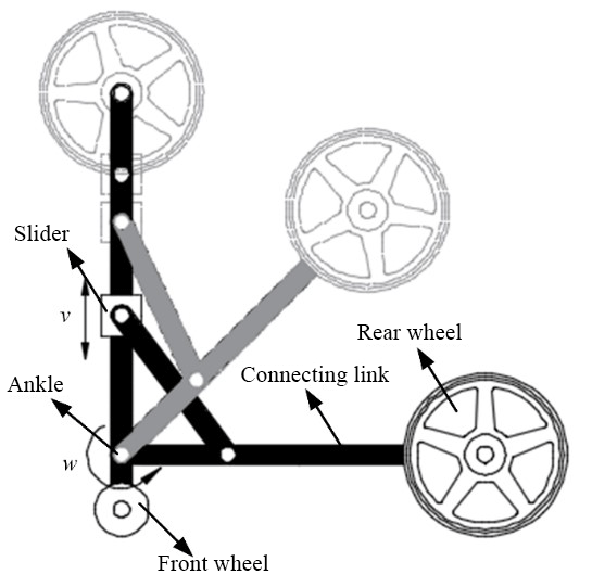
It is difficult to synthesize a reasonable mechanism to satisfy all the constraints of the hybrid robot using off-the-shelf methods. To implement three configurations with minimum linkages, the main mechanism should be designed with reference to the kinematics of the lower limbs, to determine the essential mechanism of a series chain (in deep black color), which is called a mutual linkage group (lateral side shown in Fig. 1). The development of the mechanism can therefore be transferred to design the rest linkages and pairs to link to the mutual linkage group, to implement the three configurations shown in Fig. 1. To simplify the description of the mechanism, only one side is discussed, owing to symmetry of the mechanism for both sides.

Figure 1(a) The skeleton derived from simplified basic components for a wheelchair. (b) Configuration of the mechanism transforming from the wheelchair type to the exoskeleton type while supporting the user from sit to stand. (c) Configuration of the mechanism assisting the walking in of the user in the exoskeleton type.
2.2.2 Arrangement strategy of reused actuators
For this type of robot, actuators contribute a considerable amount of weight because of the high power requirements. The arrangement strategy of actuators affects the synthesis of the mechanism. We therefore, briefly analyze the arrangement of actuators before the discussion on mechanism synthesis. The wheelchair requires one actuator to drive a wheel, so a rotational motor is the better choice than a linear motor; the support configuration requires at least one to support users while standing; and the exoskeleton requires a minimum of two actuators to drive the hip and knee joints independently (the ankle joint is a passive joint). To minimize the number of actuators, at least two actuators are necessary to implement three configurations. There are four sets of motion that should be actuated among three configurations: the rotation of wheels in the wheelchair; the standing or sitting in the support configuration; hip motion in the exoskeleton, and knee motion in the exoskeleton. The possible combination is that of one actuator to drive the wheel of the wheelchair and the knee motion in the exoskeleton, and the other actuator to drive the hip motion in the exoskeleton and standing or sitting in the support configuration. For separate motion of hip joint and sitting/standing, rotational motor and linear motor are both feasible, but coupling two motion, the linear motor is more available and it also improve the stiffness of mechanism because it is also a bar. Considering the property of motion in each configuration, the first actuator is a rotation motor with a certain gear reduction, and the other actuator is a linear motor.
2.2.3 Distributed synthesis of mechanisms
The synthesis of mechanisms is conducted according to the strategy of reused actuators, which means it is separated into two sets of combinations of motors.
First, for the mechanism of the wheelchair, the connection of the rear wheel to the mutual linkage group can be achieved using three simple connection methods, as shown in Fig. 1a (to decrease the linkages, the rear wheel is linked directly to the mutual linkage group). The choice a-III is the best because the motor used to drive the rear wheel can be used to drive the knee joint in the exoskeleton, and the rear wheel is capable of not being lifted in the support configuration. In contrast, the motor used to drive the rear wheel cannot be reused to drive the knee joint in choice a-II, and the rear wheel has to be lifted off the ground, which makes the standing and sitting unsafe. Considering the requirements of the support and exoskeleton configurations (more discussions on these will follow), the slider-crank mechanism is chosen to fold the rear wheel to the mutual linkage group, as shown in Fig. 2. Meanwhile, this mechanism also provides a mechanical interface with the mechanism of the knee joint, to couple the motion of folding the rear wheel with the motion in the knee joint and hip joint in the support and exoskeleton configurations.
Second, according to the strategy of the reused actuators in driving the hip rotation and providing support to stand and sit, the linear motor not only drives the hip motion but also the motion in the knee joint. A double slider mechanism is used in the knee joint where slider 2 in the slider-crank mechanism is mentioned above, and slider 1 on the thigh link is connected to the linear motor (Fig. 3). With respect to locking or unlocking the sliders, the support configuration and exoskeleton configuration can be implemented using the linear motor. A user can be pushed up from sitting to standing via the thigh link rotating around the knee joint, which is driven by the linear actuator when the hip joint is locked. The hip joint can be unlocked when it is needed during the standing up of the user. Thereafter, slider 2 is unlocked and pulled towards the knee joint by slider 1, by the shortening of the linear actuator. When the action of folding up the connecting link is complete, the exoskeleton configuration is achieved. In the exoskeleton configuration, as slider 2 is locked again, the connecting link and shank link are fixed to each other collinearly. The linear actuator drives slider 1 to move along the thigh link, and then induces the rotation of the hip joint. The knee joint is controlled by the motor driving the rear wheel.
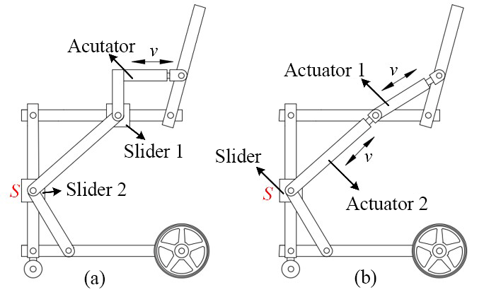
Figure 3Schematic diagram of the mechanism design satisfy the requirements of three concepts.
2.2.4 The reconfigurable mechanism
Based on the above analysis, the three configurations of the mechanism of the hybrid robot are proposed, as shown in Fig. 4, from which the mechanism is able to perform three configurations. The wheelchair is desired stable in structure, so its DoF should be zero except for that on the wheels. Support configuration is desired to support users to stand or sit, which allow the motion in knee joint and hip joint, namely 2 DoFs. Exoskeleton configuration is desired to provide users to walk and allow motion in knee and hip joints, namely 2 DoFs. According to the above mechanism, it has 3 DoFs in the wheelchair configuration and 2 DoFs in the exoskeleton configuration, owing to the folding of the connecting link into the shank link. Lock structures are added to slider 2 and the hip joint, according to the transformations between these configurations.
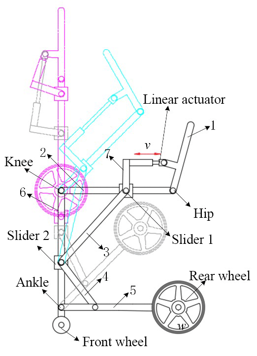
In the wheelchair configuration, the DoF of the mechanism is zero, irrespective of the motion of the footrest. The front wheels adopt omni-directional motion, and the rear wheels are ordinary driving wheels. The wheelchair can implement forward, backward, turning, and other motion by driving the rear wheels differentially, which is commonly adopted in the field of mobile robots (Chung et al., 2001; Klančar et al., 2011).
In addition, because no relative motion exists in the mechanism of the wheelchair, it is only necessary to analyze the kinematics of the mechanisms of the support and exoskeleton configurations. Furthermore, the ankle joint is designed only as a passive joint that can adapt to the motion of the feet of the user.
In the support configuration, the mechanism is completely driven by the linear actuator, which is located parallel to the thigh link. The motion of the mechanism in the support configuration therefore depends on that of the linear actuator, which means that the rotational angle of the knee joint can be described by the motion of the linear actuator.
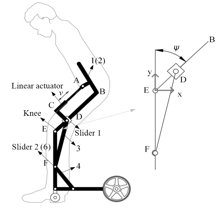
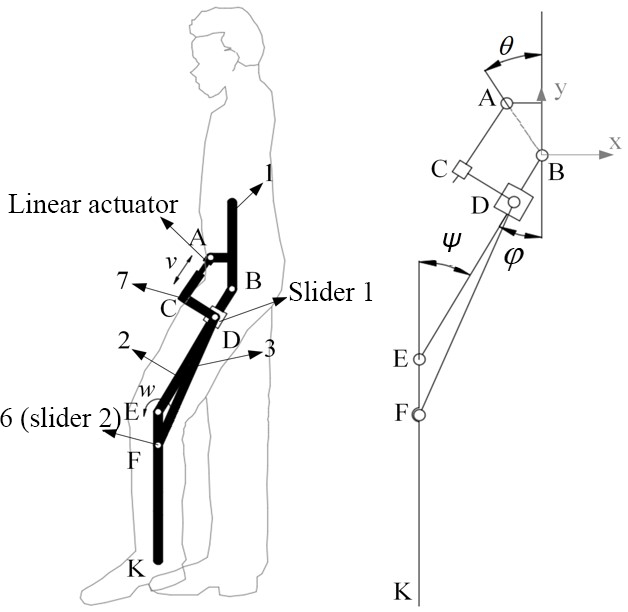
As shown in Fig. 5, a fixed coordinate is located at point E (the knee joint). Vectors , , and represent the vectors of points D, F, and B with respect to the origin in the fixed coordinate. Note that lBE, lEF, and lDF are constant, so we can obtain the following relation:
where lDE is a variable, and the constraint equation can be defined as
In triangle DEF, the following equation can be obtained:
where ψθ2 is the angle of the knee joint. Moreover, Δs is defined as the feed length of the linear actuator, which equals zero in the wheelchair, whereas ψ equals 90∘, and lBD can be denoted as
Solving Eqs. (1)–(4), the relationship between the rotational angle of the knee joint ψ and the feed length of the linear actuator can be obtained as
According to the Eq. (5), the rotation angle of the knee joint required in the supporting configuration can be obtained by controlling the linear actuator feed length. In addition, in the standing phase, although the hip joint is locked, given that the backrest is connected to the waist by a flexible belt, the trunk of users can still move forward, hence not affecting the normal standing style of the human body in this process.
To analyze the kinematics of the exoskeleton, the mechanism is simplified, as shown in Fig. 6, taking point B of the hip joint as the coordinate origin, the vertical direction as the x-axis, and the horizontal direction as the y-axis. The vectors are denoted as
The displacement coordinate of the ankle joint K is
Note that lBE, lEF, lAB, lCD and, lDF are constant values, so the following two equations can be obtained:
lAC and lDE are variables, and the constraint equations are defined as
According to the analysis in the previous sections, we can obtain the identical equations as
where θ – the angle between the line-AB and the backrest, lCD – the length of link 7, l3 – the distance between the ankle joint and the hinge joint of link 4 and link 5, l2 – the length of link 4, lAC – the length of the linear actuator.
Given that the rotational angle ψ of the knee joint is controlled directly by the rotary motor in the exoskeleton, the relationship between the hip angle φ, the length of each link, and the linear actuator needs to be determined for the kinematics of the exoskeleton. In the closed chain A–B–C–D, which has 2 DoFs and is composed of the linear actuator, thigh link, link 1, link 7, and slider 1, the rotational angle φ of the hip joint is determined by the length of the linear actuator and the position of slider 1.
The constraint equation can be obtained as
According to Eqs. (7)–(14), we can tune the angle of the hip joint by controlling the linear actuator and changing the position of slider 1, which is the basis of the implementation of normal gait in the hip joint, in the exoskeleton configuration.
To make the length of each link satisfy the basic demands of kinematics in three configurations, and to ensure that the required forces in all of the configurations are within the range of the nominal output of the linear actuator, it is necessary to optimize the dimensions of the proposed mechanisms.
4.1 Static analysis
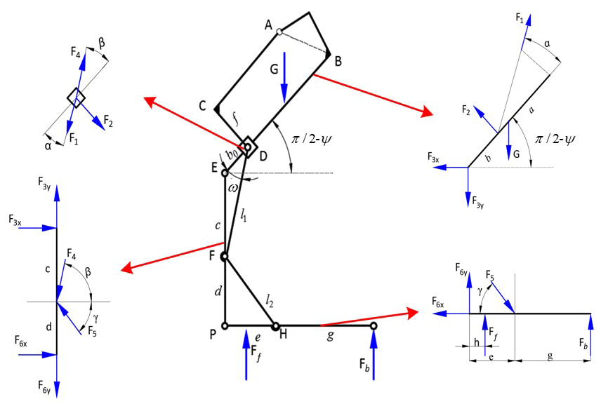
To assist the user in complete sitting and standing via the proposed robotic methods, the reliability of the robotics should be considered carefully, and the first consideration is the mechanical stability of the system, which can be analyzed by examining the statics of the proposed mechanism. In the exoskeleton, the weight of the human body and the robotic components is mainly supported by the footrests, and the swing force of the shank and thigh acting on the robot is negligible. Meanwhile, in the support configuration, the statics of the mechanism is variable with the angle of knee motion, and the wheelchair configuration is the initial status of the support configuration from wheelchair to exoskeleton. The statics of the mechanism in the support configuration is therefore analyzed.
The robot has completely symmetrical side structures; therefore, it is only necessary to consider one set of forces: the weight of the user is evenly distributed on the left and right sides of the robot. Assuming that the force on each side is G and simplifying the mechanism of the wheelchair, the external force and the internal force of the main links are shown in Fig. 7. Further, Ff and Fb denote the ground supporting forces to the front wheel and the rear wheel, respectively. To achieve equilibrium in the mechanism, the following equilibrium equations are derived:
where
Eqs. (15)–(26) can be expressed for short as follow
where
4.2 Stability of the proposed hybrid robot with wheels and legs
The stability of hybrid robot of wheels and legs should be considered, such as Beseron et al. (2006) and Bai and Low (2001). For our hybrid robot, it has two moving configurations, exoskeleton and wheelchair. So it is necessary to discuss its stability respectively. For exoskeleton configuration, users should use crutches to keep balance with wearing the exoskeleton, so it is not easy to give accurate quantitative results to calculate its CoG, when users changes their center of body mass. We can consider users can adjust their crutches and center of body mass to keep balance as most exoskeletons perform currently. For the configuration of wheelchair, users sit on the wheelchair with four wheels distrusting on the same plane. The external forces of the system are gravity and support vertical force derived from the ground. In the work of Beseron et al. (2006), control scheme is to keep the CoG away from the stability margin limit. In our work, though users can still change their center of mass within a small range, it is not difficult to guarantee its CoG within the reachable area of rectangle defined by four wheels according to the static of wheelchair system.
4.3 Linkage optimization based on the particle swarm optimization algorithm
As shown in Fig. 8, parameters of the proposed mechanism, which need to be optimized, are as follows:
- l3
-
– the distance between the ankle joint and the hinge point of link 4 on the connecting link, represented as e
- f
-
– the vertical distance between slider 1 and the linear actuator
- lDF
-
– the length of link 3, represented byl1
- lFH
-
– the length of link 4, represented byl2
- s
-
– the stroke of the linear actuator
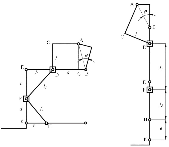
According to the human body size statistical data of Chinese adults, published by the State Bureau of Technical Supervision (CSBTS, 1988), set the length of thigh link lBE as 440 mm, and the length of shank link lEP as 400 mm. These parameters are also adjustable to enable the mechanism to match individual body size; however, to avoid confusion with respect to the kinematics and statics of the proposed mechanism, it is not discussed in this paper. According to the geometric relationships, other dimensions of linkages can be expressed as:
In the wheelchair configuration, the distance between the knee joint and slider 1 must be larger than the minimum installation distance ( mm) of the linear actuator.
During the transformation from the wheelchair configuration to the exoskeleton configuration, to ensure that slider 2 does not exceed the position of the knee joint, it is necessary to satisfy
Miranda-Linares et al. (2015) and Kralj and Tadej (1989) characterized the standing-up motion in normal subjects into four phases. Among them, the phase of ascending is the most critical phase of the process, and people with lower limb dysfunctions often fail to cope in this phase. To assist the user in standing up smoothly and safely, the linear actuator should be at least able to drive the human body to the ascending phase. Supporting devices should be able to drive the thigh link to rotate at least 45∘ around the knee joint Nango et al. (2010).
In the exoskeleton configuration, as shown in Fig. 9, the linear actuator forces the rotation of the thigh link around the hip joint by pushing slider 1, i.e., link AD drives the thigh link to rotate around point B. When the points A, B, and D are collinear, the mechanism is in the dead center position. The angle between the waist link and the line AB should therefore be greater than the maximum backward swing angle of the thigh link during walking. While in the normal gait, the swing range is −15 to 37∘; thus, the angle θ can be set as 30∘ to provide sufficient space for the backward swing. Moreover, the minimum length of the linear actuator should guarantee that the user can lift his/her thigh to ∘, and the maximum length should satisfy the swing of the user, at ∘.
where

In addition, considering ergonomics, when the human body is in a sitting posture, the most comfortable tilt angle of the backrest is 15∘ (Dong and Zhao, 2015); thus, the tilt angle of backrest in the wheelchair configuration is set as 15∘ (the angle of the backrest and vertical direction), and lAB and lBG can therefore be expressed as
The linear actuator plays a key role in the proposed robotics, and whether the supporting configuration can be implemented or not depends on its maximum output force. Therefore, it is a bottleneck for the proposed robotics to decrease the specification of the linear actuator, which can be solved by adjusting the dimensions of the mechanism. The minimum output force of the linear actuator is therefore set as the optimization goal. Meanwhile, the transmission angle decreases gradually with the increase angle of the knee joint during the standing phase, which results in the increase of the output force of actuator. However, the torque on the knee joint decreases during this phase, which results in the decrease of the output force. As a result, the maximum force provided by the linear actuator may exist at any position in the mechanism. The necessary force provided by the linear actuator should therefore be calculated theoretically during the whole process of the support configuration. According to the kinematic analysis, F0 can be represented as
Calculated from Eq. (26)
And
Thus, F0 can be expressed as
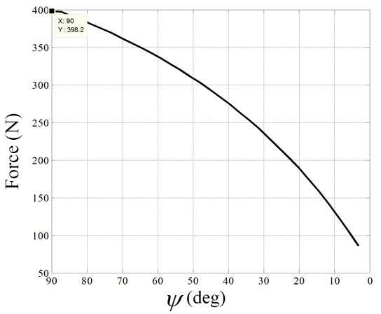
The necessary force provided by the linear actuator F0 is shown in Fig. 9 with respect to the angle of knee joint ψ. It can be found that the output force of the linear actuator decreases with the decrease of the knee joint angle in the support configuration, where the maximum force appears when the angle of the knee joint is 90∘, i.e. the initial point of the support configuration from wheelchair to exoskeleton. The optimization goal is therefore the minimization of the output force F0 in the wheelchair configuration.
In the wheelchair configuration, the relationships ψ=90∘, β=ω, , and are substituted into Eq. (39), and the optimization function can be described by Eq. (40), which has the objective of maximizing c, where c is the distance between the knee joint and slider 2 in the wheelchair configuration. The constraints of the optimization function are Eqs. (32)–(36)
To achieve optimization with nonlinear constraints, the particle swarm optimization algorithm (Kennedy, 2011) was used, and relevant theoretical calculations were performed using MATLAB tools. The results of the mechanism dimensions are shown in Table 1. According to the results, the output force of the linear actuator in the initial stage of the transferring process from the wheelchair configuration to the exoskeleton configuration is obtained as F0=398.19N.
Based on the optimization results, the maximum length of the linear actuator is 438.8 mm, whereas the minimum length is 269.4 mm. Moreover, the length of the linear actuator in different configurations can be obtained, as shown in Table 2, using Eqs. (5) and (14). It can be found that the length of the linear actuator satisfies the requirements of all the configurations of the robot.

To verify the accuracy of the optimization results of the output force of the linear actuator, a three-dimensional model of the proposed robot, established using the software SolidWorks, is imported into the simulation software ADAMS. Assuming that the user weighs 80 kg, a force of approximately 400N is applied to each side of the robot.
In the ascending phase, the output force of the linear actuator, shown in Fig. 10, decreases from the sitting to standing of the user, which is consistent with the shape of the result of the theoretical calculation, as shown in Fig. 9. The maximum force is 400N, and the profile of the force is smooth, which can ensure user comfort.
In the exoskeleton configuration, the robot needs to be able to assist the user in walking in accordance with the normal human gait; therefore, the rotation range of the hip and knee joints of the robot should meet the requirements of the range of hip and knee motion of the normal subjects, and the force exerted by the linear actuator to drive the swing of the thigh link should be within the nominal force range of the chosen actuator. Acceleration sensors (MMA7361, Freescale) were used to collect the data of the hip and knee joint angles during user walking, and the data of one gait cycle (period of 2 s) are shown in Fig. 11.
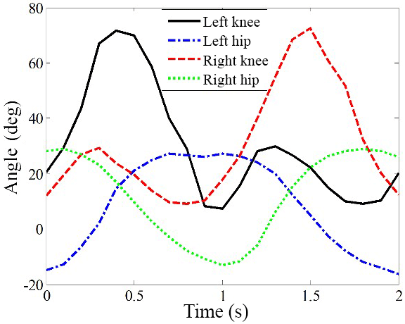
Substitute the data of the angle of the hip and knee joints into Eqs. (5) and (14), and the motion of the linear actuator in a normal gait cycle can be obtained, which is shown in Fig. 12. The calculated motion of the linear actuator and the measured rotation data of the knee joint by the acceleration sensors under the normal gait are adapted as inputs, and the motion of the exoskeleton robot can be simulated using ADAMS software. The resulting angular variation of the hip and knee joint is shown in Fig. 13. Compared with Fig. 11, it can be seen that the shape of the angle curves of the simulation results is consistent with that of normal human gait. Thus, the optimized dimensions of the links are satisfied, and the kinematics of the exoskeleton are proven effective.

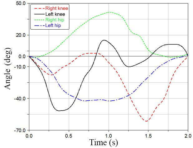
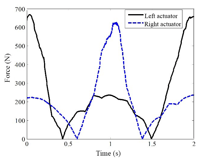
Figure 14 presents the profiles of the output force of the linear actuators on both sides during walking, when the hip joints are driven by linear actuators. The curves are not smooth, which is caused by the changing angles of the knee joint and hip joint within a gait cycle. Meanwhile, from Eq. (14), the angle of the hip joint is determined by both the linear actuator and the angle of the knee joint. Each curve has two zero points within a gait cycle, as shown in Fig. 14, i.e., the output force of the linear actuator is zero, because a special situation can exist in which the total torque due to the weight of the thigh and shank around the hip joint is zero. The peaks appear where the thigh link, driven by the linear actuator to swing backward, approaches the dead point, causing the force to increase quickly. Fortunately, it is still below the nominal force capacity of the linear actuator, and the maximum output force can be determined as less than 700N.
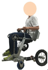
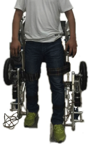
To evaluate the proposed mechanism, which aims at combining the wheelchair and exoskeleton for people with lower limb dysfunctions, a preliminary mechanical prototype was manufactured. The prototype is 29.4 kg, and its weight can be decreased via structure optimization. A healthy subject with a weight of 71 kg wore the prototype, and preliminary kinematic tests were performed on sitting, standing, and walking, without the activation of the motor. Figures 15 and 16 reveal that the system can bear the user and pass the motion, standing, sitting, and walking tests. The preliminary tests show the prototype can implement basic functions for wheelchair and exoskeleton. For security, the further test should be done including sensing, controlling of human robot interaction, as well as clinical evaluation.
Considering the poor adaptability of wheelchairs to complex terrains, there is an adverse effect on the motor recovery for lower limbs, the generation of sores and muscle atrophy induced by wheelchair sitting, and failure in long distance movements. This is due to the large consumption of energy by the upper limbs of the user walking using the exoskeleton. In this paper, a novel method is proposed, which combines an exoskeleton and a wheelchair via a reconfigurable mechanism that can overcome the individual limitations of the wheelchair and the exoskeleton. This method is challenging because the robot should be lightweight, as its function needs to be extended, when compared with that of other exoskeletons. A method of reused links and actuators is therefore proposed, which can be achieved from the perspective of a reconfigurable mechanism, thus solving the bottleneck related to weight.
Based on the analysis of the three configurations for the proposed robot, the mutual linkage group is abstracted, and three parts of the mechanisms are synthesized in distributed as well as connected means. This is achieved so that the combination of the three parts can move in a coordinated manner and perform the three configurations for human motion. The kinematics and statics are analyzed, and in conjunction with the simulation results, it can be concluded that the robot can be applied to carry and transport the user in the wheelchair configuration, support the user from changing from the sitting to standing position and finally, assist the user in walking with a normal gait in the exoskeleton configuration.
In the future, the control system for the robot will be developed, and force/torque sensors and other sensors will be installed for compliant interaction between the robot and the human body.
All the data used in this article can be obtained upon request from the corresponding author.
The manuscript was written through contributions of all authors.
The authors declare that they have no conflict of interest.
This research is supported by Tianjin Municipal
Science and Technology Department Program (Grant no. 17JCZDJC30300), the
Natural Science Foundation of China (Project No. 51475322, 51535008,
51775367, 51721003), and International Collaboration Programme (“111
Program”) (No. B16034).
Edited by: Guangbo Hao
Reviewed by: three anonymous referees
CSBTS (State Bureau of Technical Supervision): China Standards Press: 88: GB10000, Chinese adults body size [S]. Diss., 1988 (in Chinese).
Ackerman, E.: Berkeley bionics introduces eLEGS robotic exoskeleton, available at: http://spectrum.ieee.org/automation/robotics/medical-robots/berkeley-bionics-introduces-elegs-robotic-exoskeleton (last access: 26 Novemember 2014), 2010.
Aimedee, F., Gogu, G., Dai, J. S., Bouzgarrou, C., and Bouton, N: Systematization of morphing in reconfigurable mechanisms, Mech. Machine Theory, 96, 215–224, 2016
Bai, S. and Low, K.: Terrain evaluation and its application to path planning for walking machines, Adv. Robotics, 15, 729–748, 2001.
Besseron, G., Grand, C., Ben Amar, F., Plumet, F., and Bidaud, P.: Stability Control of an Hybrid Wheel-Legged Robot, in: Climbing and Walking Robots, edited by: Tokhi, M. O., Virk, G. S., and Hossain, M. A., Springer, Berlin, Heidelberg, 2006.
Borisoff, J. F., Mattie, J., and Rafer, V.: Concept proposal for a detachable exoskeleton-wheelchair to improve mobility and health, 2013 IEEE International Conference on Rehabilitation Robotics (ICORR), IEEE, University of WashingtonSeattle, WA, USA, 2013.
Chung, Y., Park, C., and Harashima, F.: A position control differential drive wheeled mobile robot, IEEE T. Ind. Electron., 48.4, 853–863, 2001.
Colombo, G., Joerg, M., Schreier, R., and Dietz, V.: Treadmill training of paraplegic patients using a robotic orthosis, J. Rehabil. Res. Dev., 37.6, 693, 2000.
Dai, J. S., Zhao, T., and Nester, C.: Sprained ankle physiotherapy based mechanism synthesis and stiffness analysis of rehabilitation robotic devices, Special Issue on Rehabilitation Robotics, Auton. Robot., 16, 207–218, 2004.
D'Angelo, L. T., Abdul-Sater, K., Pfluegl, F., and Lueth, T. C.: Wheelchair Models With Integrated Transfer Support Mechanisms and Passive Actuation, J. Med. Devices, 9.1, 011012, https://doi.org/10.1115/1.4029507, 2015.
Gary, J. M.: Wheelchair lifting device, U.S. Patent No. 5,105,915, filing date: 24 Dec, 1990, Application Number: 07/633140, 21 April 1992.
Kennedy, J.: Particle swarm optimization, Encyclopedia of machine learning, Springer, USA, 760–766, 2011.
Hwang, B. and Doyoung, J.: A wheelchair integrated lower limb exercise/rehabilitation system: Design and experimental results on the knee joint, 2012 IEEE/SICE International Symposium on System Integration (SII), IEEE, Centennial Hall Kyushu University School of MedicineFukuoka, Japan, 2012.
Kralj, A. R. and Tadej, B.: Functional electrical stimulation: standing and walking after spinal cord injury, CRC press, Boca Raton, Florida, USA, 1989.
Klančar, G., Matko, D., and Blažič, S.: A control strategy for platoons of differential drive wheeled mobile robot, Robot. Auton. Syst., 59.2, 57–64, 2011.
Liu, D and Zhao, Y.: Evaluation and Improvement of Man-Machine-Enviroment System Engineering about Old Desks and Chairs in College Teaching Building, Proceeding of the 10th Human-Machine-Environment System Engineering Conference, 2015.
Miranda-Linares, D., Alrezage, G., and Tokhi, M. O.: Control of lower limb exoskeleton for elderly assistance on basic mobility tasks, 2015 19th International Conference on System Theory, Control and Computing (ICSTCC), IEEE, Cheile Gradistei, Fundata ResortCheile Gradistei, University Dunarea de Jos of Galati, 2015.
Mu, G. and Zhang, T.: The Development Trend of Population Aging in China and Its Strategic, Journal of Huazhong Normal University: Humanities and Social Sciences Edition, 50.5, 29-36, 2011 (in Chinese).
Nango, J., Yoshizawa, H., and Liu, J.: Design of mechanism for assisting standing movement using planar linkage and gear train, J. Adv. Mech. Des. Syst., 4.2, 428–443, 2010.
Saglia, J., Dai, J. S., and Caldwell, D. G.: Geometry and kinematic analysis of a redundantly actuated parallel mechanism that eliminates singularity and improves dexterity, J. Mech. Des.-T. ASME, 130, 124501, https://doi.org/10.1115/1.2988472, 2008.
Saglia, J. A., Tsagarakis, N. G., Dai, J. S., and Caldwell, D. G.: Inverse-kinematics-based control of a redundantly actuated platform for rehabilitation, Journal of Systems and Control Engineering, P. I. Mech. Eng., 223, 53–70, 2009a.
Saglia, J. A., Tsagarakis, N. G., Dai, J. S., and Caldwell, D. G.: A high performance redundantly actuated parallel mechanism for ankle rehabilitation, Int. J. Robot. Res., 28, 1216–1227, 2009b.
Sankai, Y.: HAL: Hybrid assistive limb based on cybernics, Robotics Research, Springer, Berlin Heidelberg, 25–34, 2010.
Sanz-Merodio, D., Cestari, M., Carlos Arevalo, J., and Garcia, E.: A lower-limb exoskeleton for gait assistance in quadriplegia, 2012 IEEE International Conference on Robotics and Biomimetics (ROBIO), IEEE, Crowne Plaza Guangzhou City CentreGuangzhou, China, 2012.
Shankar, T. and Santosh, K. D.: A Hybrid Assistive Wheelchair-Exoskeleton, Proceedings of the international Convention on Rehabilitation Engineering & Assistive Technology, Singapore Therapeutic, Assistive & Rehabilitative Technologies (START) Centre, 2015.
Strausser, K. A. and Kazerooni, H.: The development and testing of a human machine interface for a mobile medical exoskeleton, 2011 IEEE/RSJ International Conference on Intelligent Robots and Systems (IROS), IEEE, Hilton San FranciscoSan Francisco, CA, USA, 2011.
Talaty, M., Esquenazi, A., and Briceno, J. E.: Differentiating ability in users of the ReWalk TM powered exoskeleton: An analysis of walking kinematics, 2013 IEEE International Conference on Rehabilitation Robotics (ICORR), IEEE, University of WashingtonSeattle, WA, USA, 2013.
Waldron, D. and Haggstrom, S.: Collapsible wheelchair, U.S. Patent No. 6,752,414, application No. 10/140,725. Family ID, 32467335, 22 June 2004.
Walsh, C. J., Endo, K., and Herr, H.: A quasi-passive leg exoskeleton for load-carrying augmentation, Int. J. Hum. Robot., 4.03, 487–506, 2007.
Wu, C., Jin, Q., and Zhao, Q.: Analysis on the obstacle traversing capability of climbing wheelchair with planetary wheel, Journal of Machine Design, 2010, 48–53, 2010 (in Chinese).
Zhao, Y.: China CDPF released the latest data on disabled population in China, Research on the disabled, A01, 11–11, 2012 (in Chinese).
Zoss, A. B., Kazerooni, H., and Chu, A.: Biomechanical design of the Berkeley lower extremity exoskeleton (BLEEX), IEEE/ASME T. Mech., 11.2, 128–138, 2006.
- Abstract
- Introduction
- Configuration synthesis of the mechanism of the hybrid human-movement-assist robot
- Kinematic analysis of the mechanism of the hybrid human-movement-assist robot
- Optimization of link length
- Simulation
- Prototype manufacture
- Conclusions and future work
- Data availability
- Author contributions
- Competing interests
- Acknowledgements
- References