the Creative Commons Attribution 4.0 License.
the Creative Commons Attribution 4.0 License.
 | 13 Mar 2019
Design of a robot-assisted exoskeleton for passive wrist and forearm rehabilitation
Mehmet Erkan Kütük
Lale Canan Dülger
Memik Taylan Daş
This paper presents a new exoskeleton design for wrist and forearm rehabilitation. The contribution of this study is to offer a methodology which shows how to adapt a serial manipulator that reduces the number of actuators used on exoskeleton design for the rehabilitation. The system offered is a combination of end-effector- and exoskeleton-based devices. The passive exoskeleton is attached to the end effector of the manipulator, which provides motion for the purpose of rehabilitation process. The Denso VP 6-Axis Articulated Robot is used to control motion of the exoskeleton during the rehabilitation process. The exoskeleton is designed to be used for both wrist and forearm motions. The desired moving capabilities of the exoskeleton are flexion–extension (FE) and adduction–abduction (AA) motions for the wrist and pronation–supination (PS) motion for the forearm. The anatomical structure of a human limb is taken as a constraint during the design. The joints on the exoskeleton can be locked or unlocked manually in order to restrict or enable the movements. The parts of the exoskeleton include mechanical stoppers to prevent the excessive motion. One passive degree of freedom (DOF) is added in order to prevent misalignment problems between the axes of FE and AA motions. Kinematic feedback of the experiments is performed by using a wireless motion tracker assembled on the exoskeleton. The results proved that motion transmission from robot to exoskeleton is satisfactorily achieved. Instead of different exoskeletons in which each axis is driven and controlled separately, one serial robot with adaptable passive exoskeletons is adequate to facilitate rehabilitation exercises.
- Article
(11242 KB) - Full-text XML
- BibTeX
- EndNote


Deficiencies in the upper extremities restrain a person's ability to go about daily life, consequently limiting one's independence. Therefore, robots are used to perform task-oriented repetitive movements in order to improve motor recovery, muscle strength and movement coordination. Stroke is one of the primary reasons for a decrease in motor function of the upper limbs of human beings. It restricts the daily, social and household activities of the patients. Therefore, rehabilitation therapy is required to recover some of the movement lost (Bayona et al., 2005; Bonita and Beaglehole, 1988; Cramer and Riley, 2008). This is accomplished by a long-term intensive and repetitive rehabilitation period. Traditional therapies not only require great effort but also require the manual assistance of physiotherapists. The one-to-one contact of the therapists with their patients leaves the therapists exhausted. Moreover, therapists have limited abilities with regard to speed, senses, strength, and repeatability.
Robot-aided therapy is a developing part of post-stroke rehabilitation care (Reinkensmeyer et al., 2004). Robotic rehabilitation systems ensure compact therapy which can be applied in repetitive, controllable and accurate manner (Kahn et al., 2006; Marchal-Crespo and Reinkensmeyer, 2009). Robotic devices can provide limitless repeatability for patients thus decreasing the effort that therapists have to make (Kwakkel et al., 2008; Lum et al., 2002). Additionally, patient performance evaluation can easily be monitored and assessed by the therapists to adjust the rest of the required therapy (Celik et al., 2010; Ponomarenko et al., 2014).
The types of exercises are grouped into two branches: active and passive exercises. The subjects move their limbs actively and apply torque and/or force in active exercises. Passive exercises are in contrast to active exercises, in which the subjects remain passive during the exercise while an active device moves the limb. Continuous passive motion (CPM) is generated in this way (Maciejasz et al., 2014).
There is a broad range of robotic systems presented for upper-extremity rehabilitation. The mechanical structure of the rehabilitation robots can be mainly grouped into two parts: “end-effector-based” and “exoskeletons”. MIT-MANUS (Krebs et al., 1998) and MIME (Lum et al., 2002) are included in the first part. End-effector-type robots cover a large workspace without having the capability to apply torques to specific joints of the arm. Having simpler control structure than exoskeletons is an advantage of end-effector-type devices. The most distal part of the robot is in contact with the patient limb. The segments of the upper extremities can be regarded as a mechanical chain. Therefore, motion in the end effector of the robot will automatically move other segments of the patient. They may cause redundant configurations of the patient's upper extremities and may risk injury. Exoskeletons are the external structural mechanisms that have joints and links that can collaborate with the human body. They transmit motion exerted by the links to the human joints, thus making them suitable for the human anatomy. Exoskeletons must be able to carry out movements within the natural limitations of a human wrist for an ergonomic design. Mechanical and control issues are more complex than end-effector-type devices. The 5 degrees of freedom (DOF) MAHI (Gupta and O'Malley, 2006), 6 DOF ARMin (Nef et al., 2008) and 7 DOF CADEN-7 (Perry et al., 2007) are some examples of exoskeletons used in upper-extremity rehabilitation. LIMPACT (Otten et al., 2015), MIT-Manus (Krebs et al., 1998) and MIME (Lum et al., 2005) are prime examples of systems designed for assisting upper-limb proximal joints (the shoulder and the elbow). On the other hand, CR-2 Haptic (Khor et al., 2014) has one rotational DOF. There are manual reconfigurations for any specific wrist movement. Systems called Universal Haptic Drive (Oblak et al., 2010), Bi-Manu-Track (Lum et al., 1993) and Supinator Extender (Allington et al., 2011) have 2 DOF. The closest configuration resembling a human wrist and a rehabilitation robot can be employed by a 3 DOF system with three revolute joints. This configuration type enhances the functionality of devices providing rehabilitation services as it allows independence for specific motions of the wrist. RiceWrist (Gupta et al., 2008) and CRAMER (Spencer et al., 2008) use parallel mechanisms for wrist and forearm rehabilitation. RiceWrist-S (Pehlivan et al., 2012) is a 3 DOF exoskeleton system which is the developed version of RiceWrist (Gupta et al., 2008). A three-axis gimbal called WristGimbal (Martinez et al., 2013) offers flexibility to adjust rotation centers of the axes in order to match the wrist center of the patient. A 3 DOF self-aligning exoskeleton given in Beekhuis et al. (2013) compensates for misalignment of the wrist and forearm. Parallelogram linkages are used for this purpose. Nu-Wrist (Omarkulov et al., 2016) is a novel self-aligning 3 DOF system allowing passive adaptation in the wrist joint.
This paper presents the design of an exoskeleton for human wrist and forearm rehabilitation. Specific wrist and forearm therapies are performed. An issue with the angular displacement limit of a robot axis was experienced. The solution method obtained by changing the design is given herein. Adapting a 6 DOF Denso robot for wrist and forearm rehabilitation is proposed. The novelty of the study is the use of an exoskeleton driven by a serial robot, which is a method that has not yet been tackled in the literature. The proposed system hybridized the end-effector-type and exoskeleton-type rehabilitation systems in order to utilize advantages and to avoid disadvantages. Precise movement transmission from robot to patient limb can be provided by using an exoskeleton which plays a guide role in the exercises. This adaptation makes the system feasible to apply torques to specific joints of the wrist and allow independent, concurrent and precise movement control. This technique offers flexibility to the users. If the user wants wrist and forearm rehabilitation, a 3-D model of the exoskeleton is designed, manufactured with 3-D printing technology and interfaced with the robot. The exoskeleton may be designed for ankle, shoulder and/or elbow applications. Therefore, a serial robot can be used as a motion provider for different types of rehabilitation. Instead of different exoskeletons having a motor for each axis, the combination of a serial robot and passive exoskeleton is enough to perform the rehabilitation exercises.
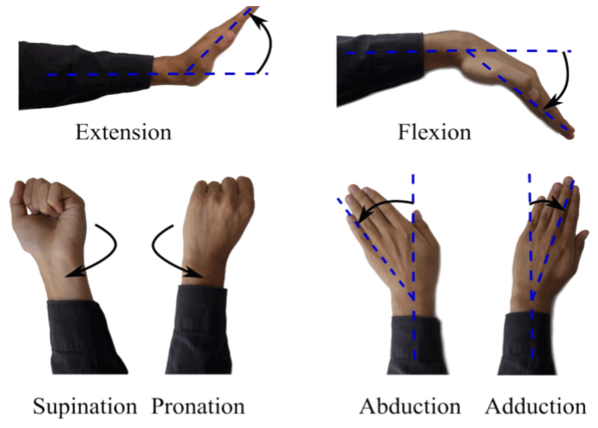
A human uses the distal parts of his/her arm (i.e., wrist, forearm) in coordination with proximal parts (i.e., elbow, shoulder) in order to carry out movements required in daily life, e.g., wrist and forearm motions such as eating, writing, opening a door, driving an automobile and so on. The wrist joint has got 2 DOF; flexion and extension (FE) and radial–ulnar deviation. Radial–ulnar deviations can also be called adduction and abduction (AA), respectively. Flexion is the bending of the wrist so that the palm approaches the anterior surface of the forearm. The extension is the reverse of flexion. Abduction (radial deviation) is the bending of the wrist towards to the thumb side. The reverse of this motion is called adduction (ulnar deviation). Pronation and supination (PS) are the movements for the forearm. Pronation is applied to a hand such that the palm turns backward or downward. Supination is the rotation of the forearm such that the palm of the hand faces anteriorly to the anatomic position (Omarkulov et al., 2016). These motions are given in Fig. 1.
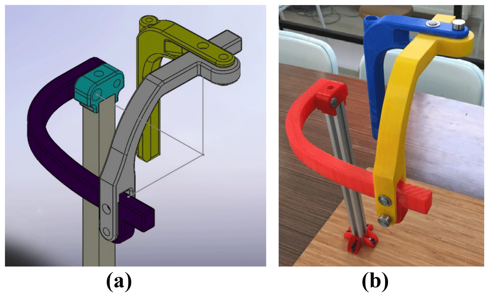
An exoskeleton has been designed for the forearm PS motion and the wrist FE and AA motions. It has 3 DOF, which are all passive. The passive joints can be locked or unlocked manually in order to restrict or enable the motions. The holes close to the axes of rotations are lock guides to constrain the movements of the links. The prototype has been made of ABS M-30 material by using 3-D printing technology for experimental assessment. STRATASYS Fortus 450 MC, which is an industry-standard 3-D printing device, has been used and the parts have been printed with 100 % infill density. The solid and manufactured models of the exoskeleton are illustrated in Fig. 2. The axes of rotations are intersected at one point, which is the wrist joint of a human.
The wrist motion is operated about an instantaneous center. Thus, the rotation axes of the exoskeleton are intersected in the wrist joint. The following design criteria for an ergonomic fit must be achieved:
- i.
The exoskeleton must fit a human wrist in terms of the segmental lengths, the anatomical range of motion and the DOF. The anatomical range of motion of the wrist is 30∘ in adduction, 20∘ in abduction, 60∘ in extension and 70∘ in flexion. The acceptable limitations for PS of the forearm are 80 and 90∘, respectively (Gopura and Kiguchi, 2007; Schiele and van der Helm, 2006; Williams et al., 2001).
- ii.
For safety, mechanical stoppers are to be located in between the links in order to prevent the range of motions being exceeded. Stoppers are available for FE and AA movements. However, there is no stopper for PS motion. Due to workable space limits of the robot, it is not possible to exceed the range of PS motion. The geometries of the links were designed by considering the details discussed above and are shown in Fig. 3a and b.

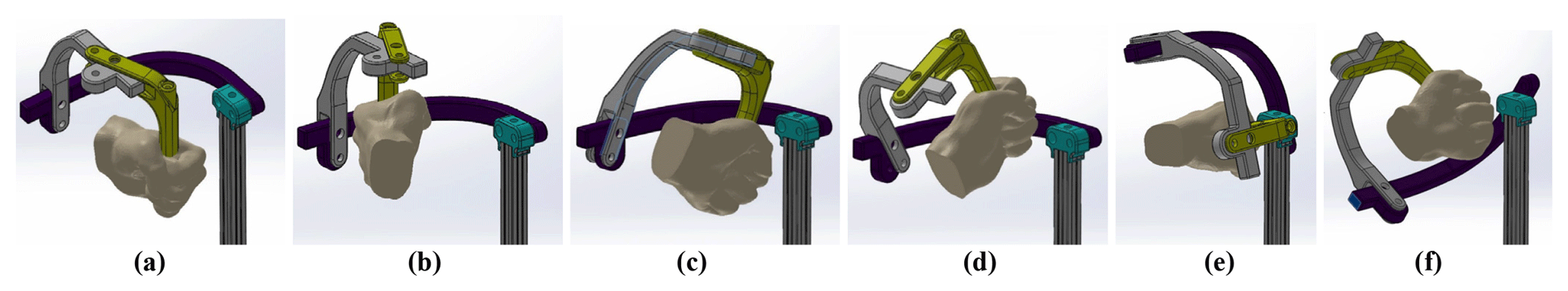
It is possible to illustrate the therapy motions with a virtual hand interface to ease visualization. Demonstration of FE, AA and PS motions are given in Fig. 4a–f, respectively. It is clear that there is no constraint on the rotation axes during the exercise; they are free to rotate. The absence of motion restrictions on the axes prevents stress formation on the parts.
The Denso robot is a 6 DOF robotic manipulator. It can communicate with MATLAB Simulink via TCP/IP. QUARC control software is supported. The QUARC software is executed in MATLAB Simulink® for real-time application (Quanser, 2018). Six amplifiers and FF (feed forward) and PID (proportional, integral and derivative) controllers provide the control of the Denso robot. PID gains have been tuned by taking the robot dynamics into consideration. Rehabilitation is one of the areas of application of the Denso robot.
A systematic way of describing the geometry of a serial chain of links and joints was proposed by Denavit and Hartenberg. It is known as Denavit–Hartenberg (DH) notation (Denavit and Hartenberg, 1955). The matrix A expressing four movements is carried out by postmultiplying the four matrices, resulting in four movements being needed for frame {j−1} to reach frame {j} (Corke, 2011). DH representation of a joint–link combination, world and joint frames, and axes of the Denso robot are given in Fig. 5a–c, respectively (Quanser, 2018; Denso Robotics, 2018).
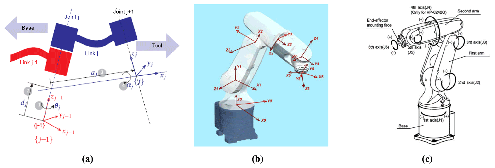
Figure 5DH representation of a joint–link combination (Corke, 2011) world frame and joint frames (Quanser, 2018), axes of the Denso robot (Denso Robotics, 2018).
The following table presents DH parameters of the Denso robotic arm to derive the robot kinematics.
Table 1DH parameters of the Denso robotic arm, where d1=0.125 m, a2=0.21 m, m, d4=0.21 m and d6=0.07 m.
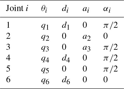
The transformation matrix for each joint can be written by using the parameters given in Table 1. Six transformation matrices are shown in Eq. (1).
Here, C and S are abbreviations of cosine and sine, respectively. The total transformation between the base of the robot and the sixth axis is as follows.
Transformation matrices for six axes given in Eq. (1) are postmultiplied in an order as given in Eq. (2). This equality is shown in Eq. (3).
where n (normal), o (orientation), a (approach) elements are for orientation, and P (position) elements are position elements relative to the reference frame. The elements of the matrix shown in the left-hand side of Eq. (3) are presented in Eqs. (4)–(7).
An overview for the inverse kinematics algorithm for finding the angular displacements of the robot links is given below:
-
Compute the location of the wrist center point (WCP) of the Denso robot by translating back along the end-effector z vector.
-
Calculate the base joint angle θ1 based on projection of WCP onto the x–y base plane.
-
Calculate θ3 through basic triangle analysis.
-
Similarly calculate θ2 with knowledge of the joint lengths. The cosine law can be used to determine the angles within the triangle formed by links 2 and 3.
-
Calculate θ5 using the inner product of the end-effector z axis and the z axis of joint 4.
-
Calculate θ4 using the triangle from [T3_6] with the robot links.
-
Calculate θ6 by using the same triangle.
Analytical and artificial approaches in Denso robot kinematics have been studied in the Mechatronics Laboratory at Gaziantep University (Almusawi et al., 2016, Kütük et al., 2017).
The Simulink model of the Denso robot kinematics is shown in Fig. 6. The location of the tip of the system is defined for xyz_0. Rotation [R] and translation [x] matrices are concatenated and the overall transformation matrix from base to end effector [T0_EE] is obtained. A transformation matrix [T6_EE] is also defined between the end effector (if available) and the sixth axis of the Denso robot. The multiplication of [T0_6] and [T6_EE] yields [T0_EE] as given in Eq. (8). If there is no end effector, [T0_EE] and [T0_6] are equal to each other and [T6_EE] is an identity matrix. If there is an end effector, [T6_EE] is defined. The multiplication of [T0_EE] and inverse of [T6_EE] matrices gives the transformation matrix of the Denso robot, [T0_6] as shown in Eq. (9). Then, the algorithm mentioned above is applied and angular displacements of the robot links are found.

The DENSO IPK (inverse position kinematics) function solves this 4×4 matrix as explained in the algorithm overview. The angular displacement results of the robot links are sent to a command file.
The joints of exoskeleton are passive, which means that there is no actuator on the exoskeleton. The Denso robot is used as a master motion provider. Three specific motions are carried out one by one. While performing a specific motion, the other two axes on the exoskeleton may be locked for accurate motion. Gravity compensation is provided by the Denso robot. While 3 DOF of the Denso robot are for keeping the wrist joint stationary, the other 3 DOF of the Robot are for generating orientation change of the wrist joint for FE, PS and AA motions. The overall system is shown in Fig. 7a, b.
The rotation axes of the exoskeleton are intersected with the wrist joint of a human, as shown in Fig. 2a. Therefore, the position of the wrist joint is not changed during the motions. However, the orientations (roll, pitch, yaw) will be changed to perform the three rehabilitation motions. When the Denso robot and the exoskeleton are mounted to each other, the end effector position of the robot is changed. The new end effector point is shifted to the human wrist from the sixth axis of the robot.
-
The robot operates PS motion by sending the trajectory data to the roll angle of the robot end effector.
-
The robot operates AA motion by sending the trajectory data to the pitch angle of the robot end effector.
-
The robot operates FE motion by sending the trajectory data to the yaw angle of the robot end effector.
The 3×3 orientation matrix [R] of the transformation matrix given in Fig. 6 is obtained by this way.
The required modifications are performed on the Simulink model. FE and PS have been performed correctly. However, the fifth axis of the Denso robot has reached the limit position during the adduction period. The motion range of Adduction must be 20∘. However, when the fifth axis reaches the limit position, the amount of adduction is 15∘. There is no problem in abduction part. Therefore it is required that fifth axis of the Denso robot is not brought to the limit angles. The adduction motion that the Denso robot has reached to the limit condition is given in Fig. 8a and b as the real system and a display from off-line programming, respectively.

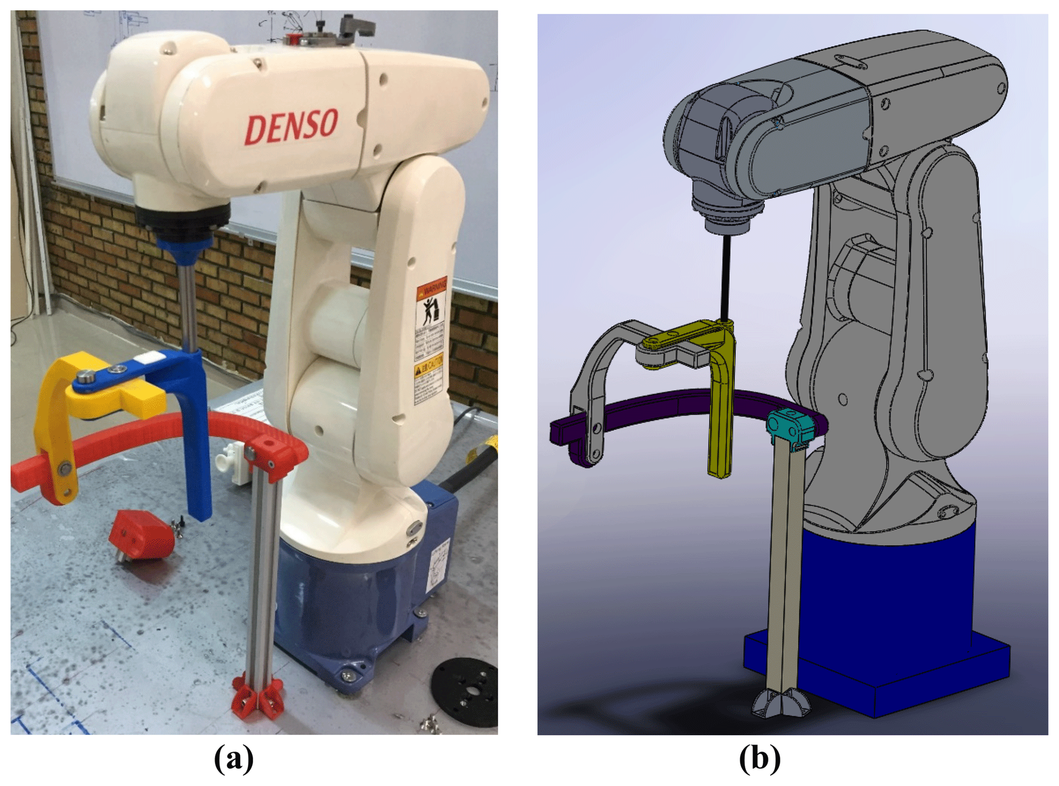
A way of discarding this problem is to make AA motion in a different exoskeleton and Denso robot configuration. A new solution is proposed by changing the exoskeleton configuration practically, without loosening the screwed connections (shown with the red arrow in Fig. 9a) between the tip of the robot and exoskeleton. The exoskeleton is used in two configurations like in Fig. 9a for FE and PS motions and Fig. 10a for the AA motion. Exoskeleton stays on a rotatable platform which can be fixed to the ground in both configurations. The rotatable system and its fixed positions are given in Figs. 9b and 10b. The exoskeleton rotates on the bearing freely. The configurations given in Figs. 9a and 10a are shifted about 90∘ with respect to each other. The changing configuration is carried out by loosening the nut and the bolt shown with yellow arrows in Fig. 9a and b, rotating the system, and then tightening the nut and the bolt. The region where the patient holds the exoskeleton is considered to be the most critical place in terms of structural issues. This part is manufactured as hollow. The rod that connects the robot with the exoskeleton is passed through this hollow and the screw connection is used at the bottom. Therefore, this part can be considered as strong as a metal rod.

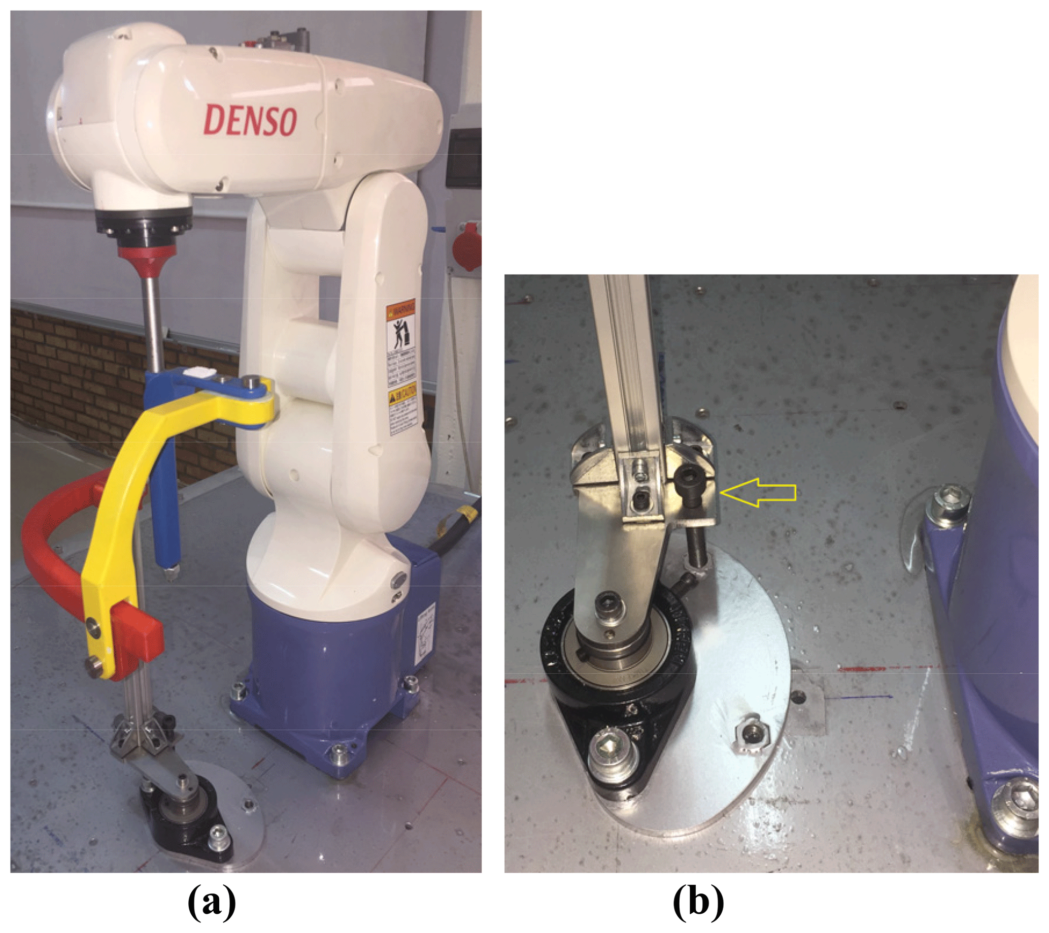
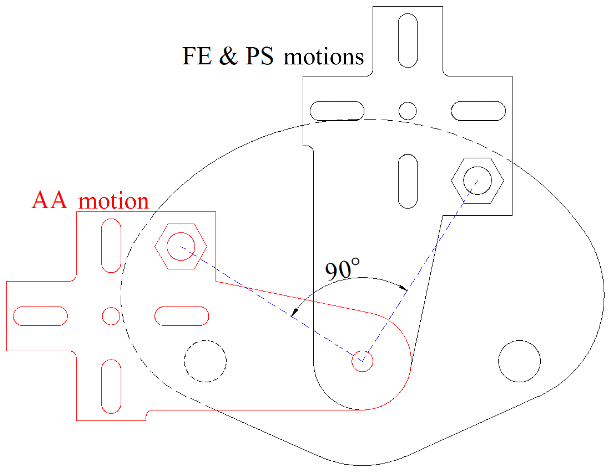
Two nuts shown in the yellow circles in Fig. 9b are for fixing the desired configuration to the ground. The nuts are located on the part that is under the bearing. The positions of them are defined by considering the shifting angle, 90∘, shown in Fig. 11.

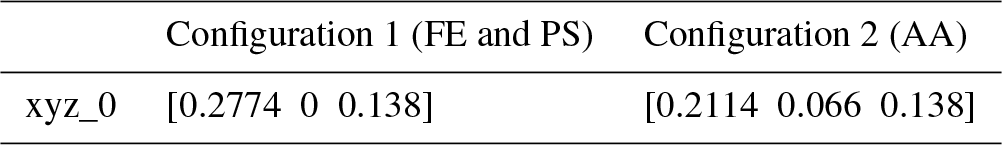

Human wrist positions are different in both configurations. The human wrist positions are given in Fig. 12. Therefore, the Simulink program shown in Fig. 6 has been modified for each motion. Positions of the wrist joint in a global frame (xyz_0) are given in Table 2. The transformation matrices between the tip of the robot and wrist joints and are given in Eqs. (10) and (11). AA motion in Configuration 2 is controlled by the changing roll angle of the end effector.
The overall system, including the base for the forearm for two configurations, is shown in Fig. 13a and b. The base, which is a part between the forearm and the table, takes the main weight of the arm. The base with padding and straps is located on a linear slide rail. It is used to adjust the location of the wrist joint. Actually, there is a slight linear eccentricity between the bones corresponding to FE and AA (Gopura and Kiguchi, 2007; Schiele and van der Helm, 2006; Omarkulov et al., 2016). This linear slide rail is a passive DOF to compensate the misalignment during the exercise. Therefore, self-alignment is provided naturally during AA motion by changing the grasping level slightly and sliding the base on the linear rail. It is shown in Fig. 13c.

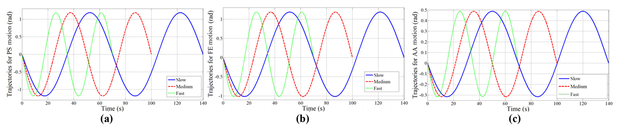
Trajectories are obtained for FE, AA and PS motions. There are three different velocity levels in each motion. They are slow, medium and fast with periods of 70, 50 and 35 s, respectively, as given in Fig. 14. The amplitudes of the trajectories are selected as defined in Sect. 2. The motion intervals are ±70∘ for PS, +70 and −60∘ for FE, +30 and −20∘ for AA motion.
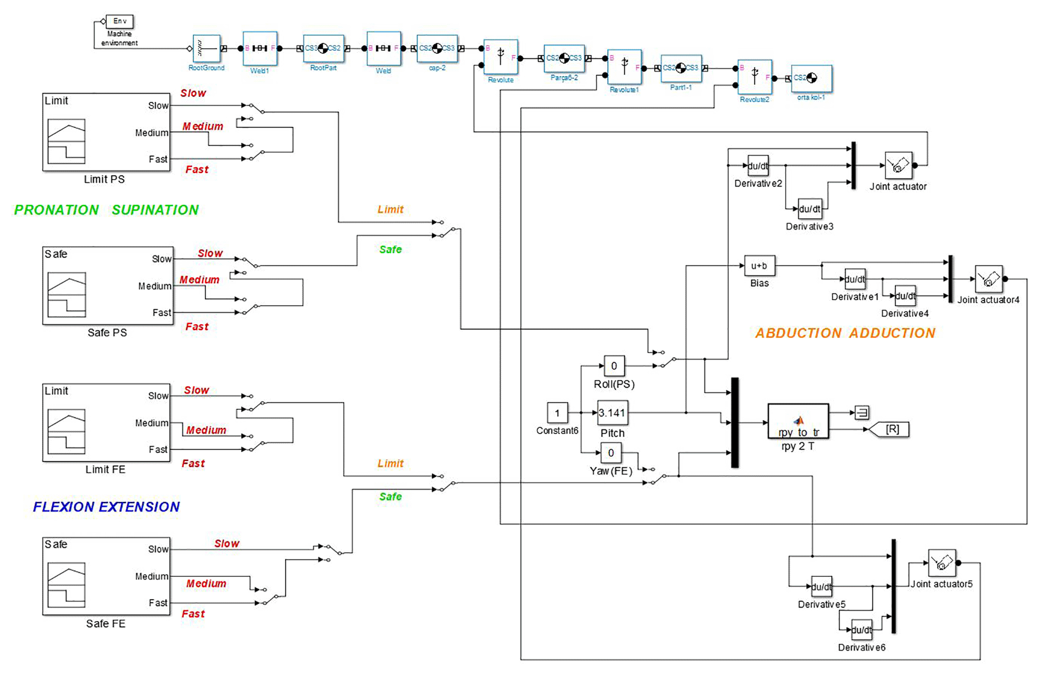
The velocity level is defined based on the therapy that the patient needs. The trajectories given in Fig. 14 are embedded in the blocks in Fig. 15. The desired motions (PS, FE, AA) with desired velocity (slow, medium, fast) are selected by manual switches given in Fig. 15.
The model including FE and PS trajectories and SimMechanics blocks of the exoskeleton is illustrated in Fig. 15. The trajectories feed the orientation of the wrist point in terms of roll, pitch and yaw angles. They form the rotation matrix named [R] that was given in Fig. 6. The amplitudes of the trajectories may be changed for the patients having different level of illnesses. Therefore, trajectory choices called limit and safe are also included. SimMechanics blocks are also used to visualize the instantaneous configuration of the exoskeleton. The model for AA motion is very similar to Fig. 15.
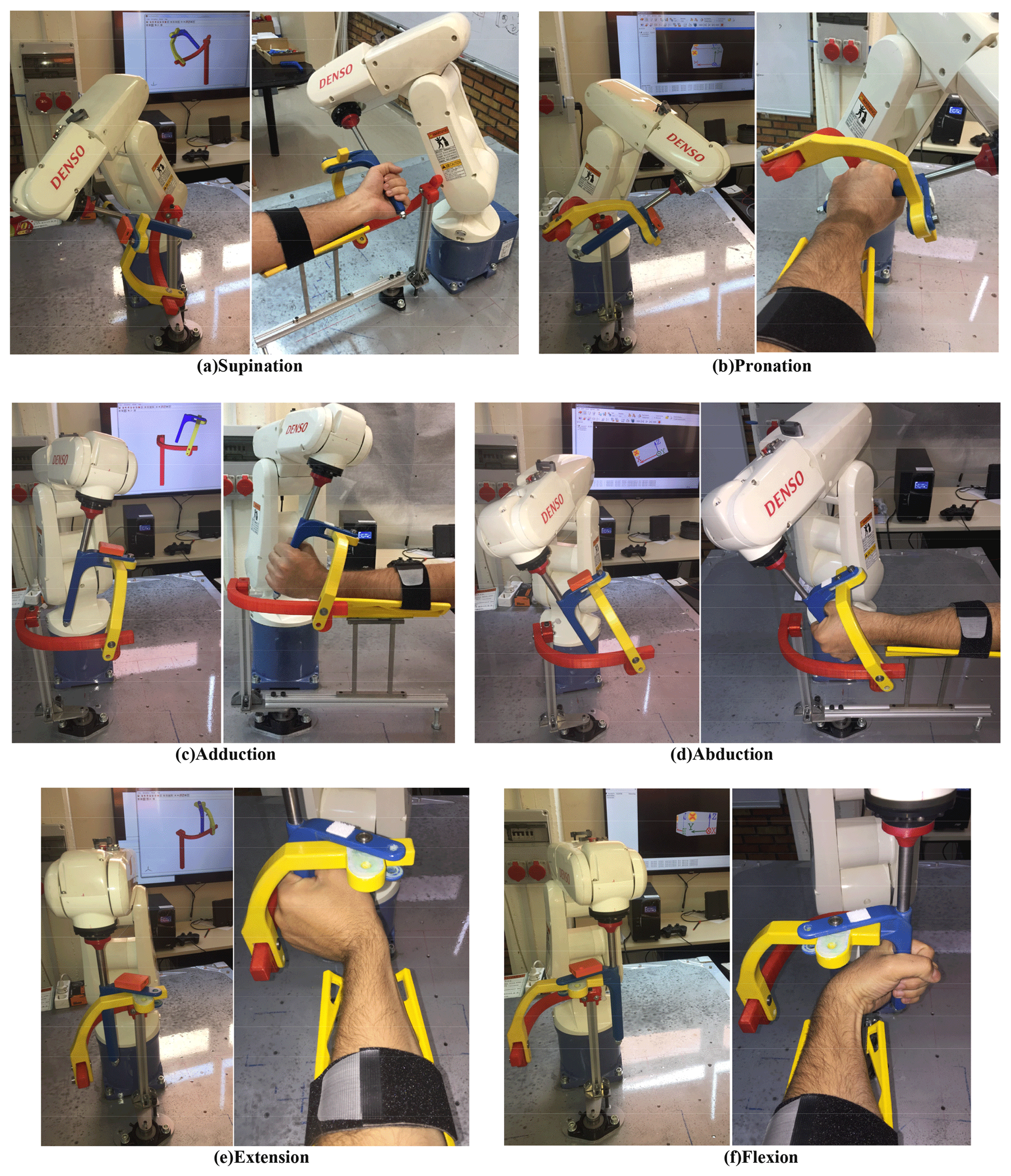
The models developed are run and the three motions are obtained within anatomical ranges. The wireless motion tracker MTw Awinda is assembled on the exoskeleton. The orientations of the exoskeleton are acquired on a wireless interface (XSENS, 2018). The angular orientation of the motion tracker and simultaneous configuration of the exoskeleton can be displayed in real time. PS, FE and AA motions with a real human limb are given in Fig. 16a–f.
The recorded angular orientation data by MTw Awinda for three velocity levels in PS, FE and AA motions are shown in Fig. 17a, c and e, respectively. Angular displacement characteristics of the robot links for PS, FE and AA motions are depicted in Fig. 17b, d and f, respectively. Data from robot links are taken for medium velocity level during each motion.
Motion transmission from robot to exoskeleton is provided. The motors of the robot are strong enough to make the limbs trace the given trajectories. There are slight delay type errors in the measurements. They are the sum of the errors from the robot itself, bias error of the sensor and error from the location of the sensor.
The contribution of this study is to provide an application of a serial-robot-driven passive exoskeleton for human wrist and forearm rehabilitation. A potential use of the proposed system is generating continuous passive motion for physiotherapy. The designed exoskeleton has been interfaced with a serial robot and adapted for upper-extremity rehabilitation. A study about an exoskeleton driven by a serial robot has not yet been explored in the literature. The investigation of kinematic parameters required for the proper use of the designed exoskeleton has been completed. One extra passive DOF is added under the base of forearm in order to provide the self-alignment of limb–exoskeleton axes. Inverse kinematics analysis has been studied to perform the required exercises. The wrist joint has been taken as stationary. Thus a fictitious wrist joint has been defined. Orientation changes in roll, pitch and yaw angles of the fictitious point have been applied and exercises in FE, PS and AA have been performed. Trajectories for FE, AA and PS motions are performed successively with three different velocity levels. The accuracy of the exercises is validated by the signals taken from the wireless motion tracker, MTw Awinda.
This study can be regarded as a design guide for the rehabilitation of other limbs. Using a printable exoskeleton offers flexibility to the users. The exoskeletons may also be designed for ankle, shoulder and/or elbow applications. They can be designed to be compatible with the robot and then manufactured by 3-D printing technology in an easy and cheap way. Therefore, a serial robot can be used as a master motion provider for different types of rehabilitation. The use of this technique is very feasible in limbs with a common rotation center. For example, the human shoulder has 3 DOF, all of which rotate about a common rotation center. Knee and ankle also have common rotation centers. Thus, using a serial robot and passive exoskeleton systems will be more practical instead of exoskeleton systems with motors on each axis. Adapting the inverse kinematics model is very easy for different types of rehabilitation.
The data in this study can be requested from the corresponding author.
MEK, LCD and MTD discussed and decided on the methodology in the study. Primary design, complete kinematics analysis and experiments have been performed by MEK. MTD proposed the motion characteristics.
The authors declare that they have no conflict of interest.
Special thanks to the Scientific Research Projects Unit of Gaziantep University
for financial support (project number: MF. DT.17.13) and Physical Treatment
and Rehabilitation therapist İbrahim Küçükcan for his
valuable suggestions.
Edited by: Guimin
Chen
Reviewed by: Pinar Boyraz Baykas and two anonymous
referees
Allington, J., Spencer, S. J., Klein, J., Buell, M., Reinkensmeyer, D. J., and Bobrow, J.: Supinator Extender (Sue): A pneumatically actuated robot for forearm/wrist rehabilitation after stroke, in: Annual International Conference of the IEEE Engineering in Medicine and Biology Society, Boston, MA, USA, 30 August–3 September 2011, https://doi.org/10.1109/IEMBS.2011.6090459, 2011.
Almusawi R. J., Dülger L. C., and Kapucu S.: A new neural network approach in solving inverse kinematics of robotic arm (Denso VP6242), Comput. Intel Neurosc., 2016, 5720163, https://doi.org/10.1155/2016/5720163, 2016.
Bayona, N., Bitensky, J., Salter, K., and Teasell, R.: The role of task-specific training in rehabilitation therapies, Top. Stroke Rehabil., 12, 58–65, https://doi.org/10.1310/BQM5-6YGB-MVJ5-WVCR, 2005.
Beekhuis, J. H., Westerveld, A. J., Van der Kooij, H., and Stienen, A. H. A.: Design of a self-aligning 3-Dof actuated exoskeleton for diagnosis and training of wrist and forearm after stroke, in: IEEE 13th International Conference on Rehabilitation Robotics (ICORR), Seattle, WA, USA, 24–26 June 2013, https://doi.org/10.1109/ICORR.2013.6650357, 2013.
Bonita, R. and Beaglehole, R.: Recovery of motor function after stroke, Stroke, 19, 1497–1500, https://doi.org/10.1161/01.STR.19.12.1497, 1988.
Celik, O., O'Malley, M., Boake, C., Levin, H., Yozbatiran, N., and Reistetter, T.: Normalized movement quality measures for therapeutic robots strongly correlate with clinical motor impairment measures, IEEE Transactions on Neural Systems and Rehabilitation Engineering, 433–444, https://doi.org/10.1109/TNSRE.2010.2047600, 2010.
Corke, P.: Robotics, vision and control, fundamental algorithms in Matlab®, Springer, 2011.
Cramer, S. and Riley, J.: Neuroplasticity and brain repair after stroke, Curr. Opin. Neurol., 21, 76–82, https://doi.org/10.1097/WCO.0b013e3282f36cb6, 2008.
Denavit, J. and Hartenberg, R. S., A kinematic notation for lower-pair mechanisms based on matrices, J. Appl. Mech., 1, 215–221, 1955.
Denso Robotics: https://www.densorobotics.com/, last access: 20 November 2018.
Gopura, R. and Kiguchi, K.: Development of an exoskeleton robot for human wrist and forearm motion assist, in: International Conference on Industrial and Information Systems, Penadeniya, Sri Lanka, 9–11 August 2007, https://doi.org/10.1109/ICIINFS.2007.4579235, 2007.
Gupta, A. and O'Malley, M. K.: Design of a haptic arm exoskeleton for training and rehabilitation, IEEE/ASME Transactions on Mechatronics, 11, 280–289, https://doi.org/10.1109/TMECH.2006.875558, 2006.
Gupta, A., O'Malley, M. K., Patoglu, V., and Burgar, C.: Design, control and performance of ricewrist: a force feedback wrist exoskeleton for rehabilitation and training, Int. J. Rob. Res., 27, 233–251, https://doi.org/10.1177/0278364907084261, 2008.
Kahn, L., Lum, P. S., Rymer, W. Z., and Reinkensmeyer, D. J.: Robot-assisted movement training for the strokeimpaired arm: does it matter what the robot does?, J. Rehabil. Res. Dev., 43, 619–629, 2006.
Khor, K. X., Chin, P. J. H., Hisyam, A. R., Yeong, C. F., Narayanan, A. L. T., and Su, E. L. M.: Development of CR2-Haptic: a compact and portable rehabilitation robot for wrist and forearm training, in: IEEE Conference on Biomedical Engineering and Sciences (IECBES), Kuala Lumpur, Malaysia, 8–10 December 2014, https://doi.org/10.1109/IECBES.2014.7047535, 2014.
Krebs, H., Hogan, N., Aisen, M., and Volpe, B.: Robot-aided neurorehabilitation, IEEE T. Rehabil. Eng., 6, 75–87, https://doi.org/10.1109/86.662623, 1998.
Kütük, M. E., Daş, M. T., and Dülger, L. C.: Forward and inverse kinematics analysis of Denso robot, in: Proceedings of the International Symposium of Mechanism and Machine Science, 2017, Baku, Azerbaijan, 11–14 September 2017, 71–78, 2017.
Kwakkel, G., Kollen, B. J., and Krebs, H.: Effects of robot-assisted therapy on upper limb recovery after stroke: A systematic review, Neurorehab. Neural Re., 22, 111–121, https://doi.org/10.1177/1545968307305457, 2008.
Lum, P. S., Burgar, C. G., Shor, P. C., Majmundar, M., and Van Der Loos, M.: Robot-assisted movement training compared with conventional therapy techniques for the rehabilitation of upper limb motor function after stroke, Arch. Phys. Med. Rehab., 83, 952–959, https://doi.org/10.1053/apmr.2001.33101, 2002.
Lum, P. S., Burgar, C. G., Van Der Loos, M., Shor, P. C., Majmundar, M., and Yap, R.: The MIME robotic system for upper-limb neuro-rehabilitation: Results from a clinical trial in subacute stroke, in: 9th International Conference on Rehabilitation Robotics (ICORR) 2005, Chicago, IL, USA, 28 June–1 July 2005, https://doi.org/10.1109/ICORR.2005.1501153, 2005.
Lum, S., Reinkensmeyer, D., and Lehman, S.: Robotic assist devices for bimanual physical therapy: preliminary experiments, IEEE T. Rehabil. Eng., 1, 185–191, https://doi.org/10.1109/86.279267, 1993.
Maciejasz, P., Eschweiler, J., Gerlach-Hahn, K., Jansen-Troy, A., and Leonhardt, S.: A survey on robotic devices for upper limb rehabilitation, J. Neuroeng. Rehabil., 11, 3, https://doi.org/10.1186/1743-0003-11-3, 2014.
Marchal-Crespo, L. and Reinkensmeyer, D.: Review of control strategies for robotic movement training after neurologic injury, J. Neuroeng. Rehabil., 6, 20, https://doi.org/10.1186/1743-0003-6-20, 2009.
Martinez, J., Ng, P., Lu, S., Campagna, M., and Celik, O.: Design of wrist gimbal: a forearm and wrist exoskeleton for stroke rehabilitation, in: IEEE 13th International Conference on Rehabilitation Robotics (ICORR) 2013, Seattle, WA, USA, 24–26 June 2013, https://doi.org/10.1109/ICORR.2013.6650459, 2013.
Nef, T., Mihelj, M., Kiefer, G., Perndl, C., Muller, R., and Riener, R.: Armin-exoskeleton for arm therapy in stroke patients, in: IEEE 10th International Conference on Rehabilitation Robotics (ICORR) 2007, Noordwijk, the Netherlands, 13–15 June 2007, https://doi.org/10.1109/ICORR.2007.4428408, 2008.
Oblak, J., Cikajlo, I., and Matjacic, Z.: Universal haptic drive: a robot for arm and wrist rehabilitation, IEEE T. Neur. Sys. Reh., 18, 293–302, https://doi.org/10.1109/TNSRE.2009.2034162, 2010.
Omarkulov, N., Telegenov, K., Zeinnullin, M., and Tursynbek, I.: Preliminary mechanical design of nu-wrist: a 3 dof self-aligning wrist rehabilitation robot, in: 6th IEEE International Conference on Biomedical Robotics and Biomechatronics (BioRob), Singapore, Singapore, 26–29 June 2016, https://doi.org/10.1109/BIOROB.2016.7523753, 2016.
Otten, A., Voort, C., Stienen, A., Aarts, R., van Asseldonk, E., and van der Kooij, H.: LIMPACT: a hydraulically powered self-aligning upper limb exoskeleton, IEEE/ASME Transactions on Mechatronics, 20, 2285–2298, https://doi.org/10.1109/TMECH.2014.2375272, 2015.
Pehlivan, A., Lee, S., and O'Malley, M.: Mechanical design of RiceWrist-S: a forearm-wrist exoskeleton for stroke and spinal cord injury rehabilitation, in: 4th IEEE RAS & EMBS International Conference on Biomedical Robotics and Biomechatronics (BioRob), Rome, Italy, 24–27 June 2012, https://doi.org/10.1109/BioRob.2012.6290912, 2012.
Perry, J. C., Rosen, J., and Burns, S.: Upper-limb powered exoskeleton design, IEEE/ASME Transactions on Mechatronics, 12, 408–417, https://doi.org/10.1109/TMECH.2007.901934, 2007.
Ponomarenko, Y., Aubakir, B., Hussain, S., and Shintemirov, A.: An end-effector based upper-limb rehabilitation robot: Preliminary mechanism design, in: 10th France-Japan/8th Europe-Asia Congress on Mecatronics, Tokyo, Japan, 27–29 November 2014, https://doi.org/10.1109/MECATRONICS.2014.7018564, 2014.
Quanser: https://www.quanser.com/, last access: 20 November 2018.
Reinkensmeyer, D. J., Emken, J., and Cramer, S.: Robotics, motor learning, and neurologic recovery, Ann. Rev. Biomed. Eng., 6, 497–525, https://doi.org/10.1146/annurev.bioeng.6.040803.140223, 2004.
Schiele, A. and van der Helm, F. C. T.: Kinematic design to improve ergonomics in human machine interaction, IEEE T. Neur. Sys. Reh., 14, 456–469, https://doi.org/10.1109/TNSRE.2006.881565, 2006.
Spencer, S. J., Klein, J., Minakata, K., Le, V., Bobrow, J. E., and Reinkensmeyer, D. J.: A low cost parallel robot and trajectory optimization method for wrist and forearm rehabilitation using the WII, in: 2nd IEEE RAS & EMBS International Conference on Biomedical Robotics and Biomechatronics, Scottsdale, AZ, USA, 19–22 October 2008, https://doi.org/10.1109/BIOROB.2008.4762902, 2008.
Williams, D., Krebs, H., and Hogan, N.: A robot for wrist rehabilitation, in: Conference Proceedings of the 23rd Annual International Conference of the IEEE Engineering in Medicine and Biology Society), Istanbul, Turkey, Turkey, 25–28 October 2001, https://doi.org/10.1109/IEMBS.2001.1020443, 2001.
XSENS: https://www.xsens.com/, last access: 20 November 2018.