the Creative Commons Attribution 4.0 License.
the Creative Commons Attribution 4.0 License.
 | 07 Feb 2018
Design and evaluation of a continuum robot with extendable balloons
Efe Yamac Yarbasi
This article presents the design and preliminary evaluation of a novel continuum robot actuated by two extendable balloons. Extendable balloons are utilized as the actuation mechanism of the robot, and they are attached to the tip from their slack sections. These balloons can extend very much in length without having a significant change in diameter. Employing two balloons in an axially extendable, radially rigid flexible shaft, radial strain becomes constricted, allowing high elongation. As inflated, the balloons apply a force on the wall of the tip, pushing it forward. This force enables the robot to move forward. The air is supplied to the balloons by an air compressor and its flow rate to each balloon can be independently controlled. Changing the air volumes differently in each balloon, when they are radially constricted, orients the robot, allowing navigation. Elongation and force generation capabilities and pressure data are measured for different balloons during inflation and deflation. Afterward, the robot is subjected to open field and maze-like environment navigation tests. The contribution of this study is the introduction of a novel actuation mechanism for soft robots to have extreme elongation (2000 %) in order to be navigated in substantially long and narrow environments.
- Article
(13637 KB) - Full-text XML
- BibTeX
- EndNote


In order to achieve a high level of precision, rigidity has long been an optimization criterion for robot designers (Grossard et al., 2013). This resulted in very stiff robots that consist of rigid links. Although rigid-link robots dominate the industry, they cannot be of any help for some cases of diagnostic, pipe inspection, or medical applications, where a videoscope is used to access remote locations through narrow holes for visualization. In such operations, flexibility of the manipulators would help greatly to reach difficult-to-access sites and complete the task with high dexterity (Rus and Tolley, 2015). The idea of designing and developing a robot that can be easily guided through unstructured, substantially-long and narrow environments to perform exploratory operations such as for natural disaster relief, or pipe inspection (Majidi, 2014) was the motivation that led to this research (see Fig. 1).
In order to achieve high maneuverability, a soft continuum-type design (Robinson and Davies, 1999) is utilized for the target application. In such applications, soft robots are safe to work with, since they are made of compliant materials (Conrad and Zinn, 2015). Continuum robots generally behave like some animal organs, called muscular-hydrostats (Kier and Smith, 1985), even though they consist of a backbone. Since this backbone is a deformable structure rather than a rigid spine, continuum robots are moved via deformation of the backbone (Walker, 2013). Backbones bend continuously along their length via elastic deformation and produce motion by generating smooth curves (Robinson and Davies, 1999). Theoretically, they are able to take any shape in the working environment. Therefore, these types of robots are also named as hyper-redundant since they have a very large number (or infinite) of active degrees of freedom (DOF) (Chirikjian and Burdick, 1994; Kang et al., 2013). An advantage of having a deformable low-stiffness backbone is that these types of robots generate little resistance to compressive forces. Thus, they can conform to obstacles (Chirikjian and Burdick, 1990). This fact also enables the robots to work in unstructured environments, where a robot cannot rely on a detailed and accurate model of the environment (Katz et al., 2008) and may run into unexpected obstacles. These advantages make this class of robots well-suited for highly dexterous tasks and tasks that include environmental uncertainty (Katzschmann et al., 2015). With utilization of newly developed compliant matters and fabrication techniques and utilizing these matters in continuum robots, they can be enabled to tolerate very high strains and extreme configurations (Laschi et al., 2016). Backbones can be axially extended by utilizing different mechanisms, for example by actuating antagonistic tendons that are placed about the longitudinal axis (Chirikjian and Burdick, 1994) with the option of spring loading (Tonapi et al., 2015) or having telescopic precurved concentric tubes along the backbone and rotating them independently (Swaney et al., 2015). A locally actuated backbone continuum robot design is the closest to the biological continuum structures (Walker, 2013). Backbone of these robots is directly formed by the actuators. This type of robots may also consist of modules, and each module can be actuated independently in order to enable the backbone to get into the desired configuration. A surgical instrument that consists of five successive flexible segments utilizes McKibben actuators (Chou and Hannaford, 1996) has been presented in the literature (Moers et al., 2012). This manipulator uses pneumatic actuators in a parallel combination in each of its segments and controls the position of the end effector by independently controlling McKibben actuators. High precision can be achieved because of the stiffness of the manipulator and high pressures in the actuators. A similar design utilizing three fiber reinforced elastomeric enclosures in parallel combination has also been presented (Bishop-Moser et al., 2012). Another soft manipulator has been designed, and its deformation characteristics are analyzed in detail while performing tasks (Marchese et al., 2015). As one might expect, an octopus arm has been a great example of a soft, continuum-type manipulator from nature. It has been studied in detail and a manipulator that mimics an octopus arm has been designed (Calisti et al., 2011; Laschi et al., 2012). This robot is operated with cables and shape memory alloy springs to achieve high dexterity.
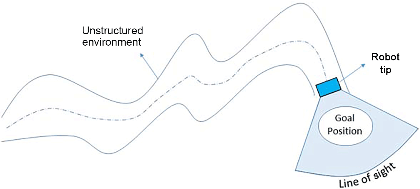
Figure 1A robot navigating through an unstructured environment, serving a screening procedure.
Soft robots can experience large deformations due to their compliant structure (Laschi et al., 2016; Cianchetti et al., 2015). The typical axial elastic strains attained in the literature are in the order of 40 % (Follador et al., 2012), 200 % (Ranzani et al., 2015), and 300 % (Hawkes et al., 2016). The dynamics of a modular compliant robot is rigorously derived (Godage et al., 2016). However, navigating in substantially long and narrow environments, or accessing remote locations might benefit from much higher strains such as 1000 %. Even though they are precise, modular robots fail to achieve such high strains. To the best of our knowledge, none of the state-of-the-art designs could tolerate such high strains when this work was completed (Yarbasi, 2016). However, a new kind of robots, so-called vine robots, has been recently proposed which can lengthen by thousands of percent by growth (Hawkes et al., 2017).
In this study, a soft-continuum robot with a novel actuation mechanism is presented. The robot is of locally actuated backbone type. The backbone composes of two extendable balloons in a parallel configuration, and they provide the actuation by means of changing air volumes in the balloons. In contrast to examples in the literature, the actuators extend in length, tolerating extreme axial strain, while their diameters stay almost constant as they are pressurized. Apart from this advantage, the proposed design inherently has the ability to utilize contact forces to guide itself through an unstructured environment. This paper presents the design, prototype development, characterization and experimental evaluation of the proposed continuum robot prototype.
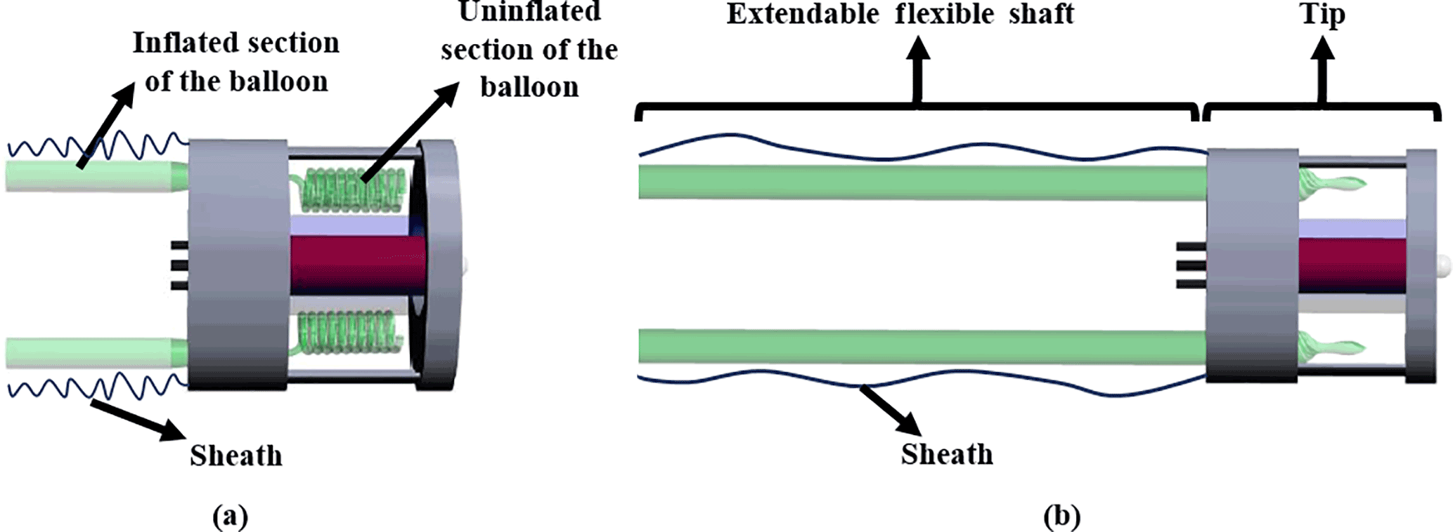
Figure 2Schematic representation of the robot and the inflation process. (a) Uninflated robot in the initial condition, (b) inflated robot.
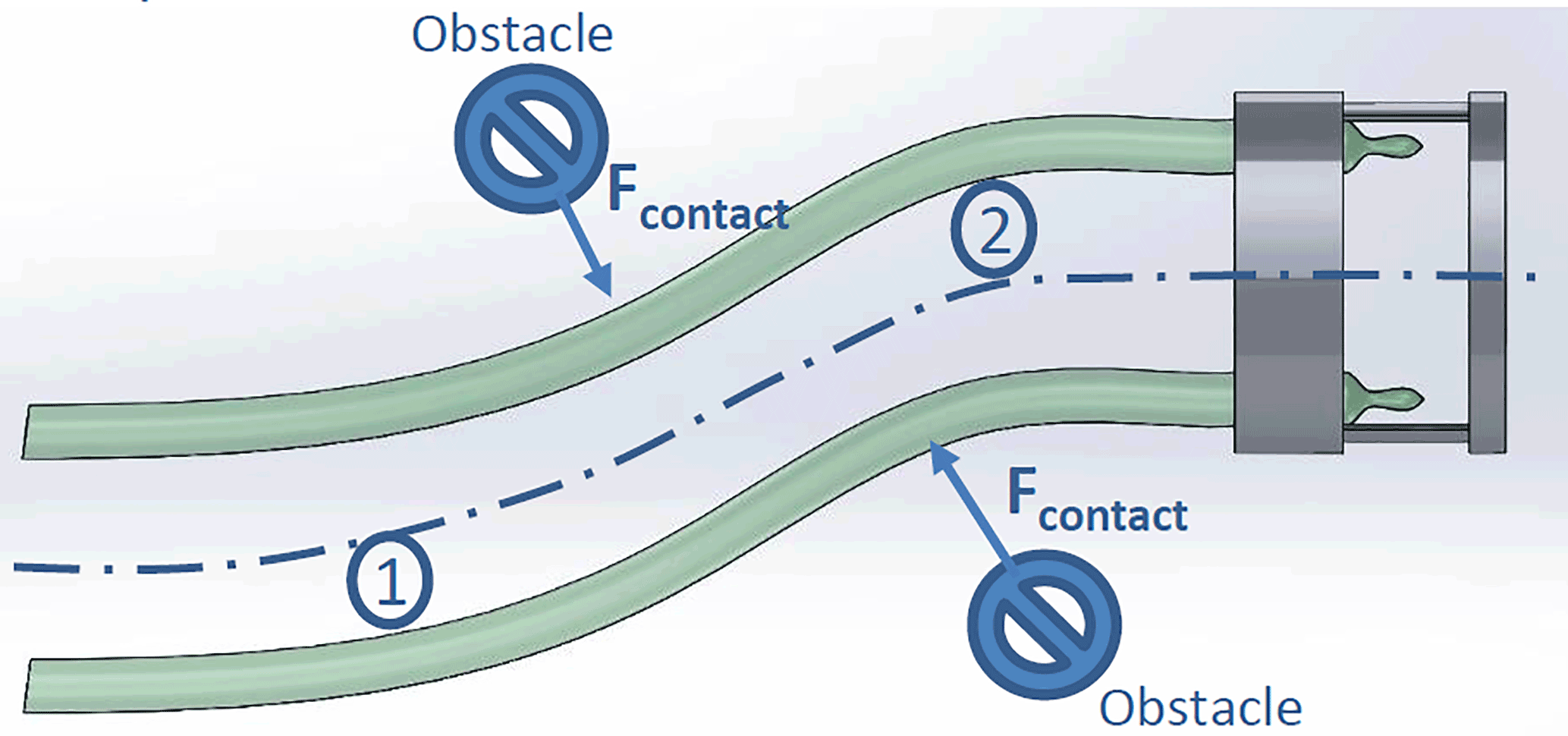
Figure 3Navigation through obstacles is demonstrated. In region 1, the lower balloon is inflated more in order to have a curvature to avoid lower obstacle. A similar procedure is followed in region 2.
The proposed continuum robot is composed of two balloons, a tip and a flexible extendable sheath as illustrated in Fig. 2. The sheath is used to keep the inflated sections of the balloons together by constraining them in the radial direction. The sheath and the inflated balloons form the flexible and extensible shaft of the continuum robot. The tip, on the other hand, is a solid structure that contains the uninflated sections of the balloons. The balloons used in this study are called long or cylindrical balloons. They are able to elongate much in length without having a very significant change in diameter. The inflated sections of the balloons are represented as the green tubes and the uninflated sections are shown as helical structures in the tip in Fig. 2. During inflation, the balloons start to inflate from the proximal section and the inflated section progresses towards the distal end. While a balloon is inflating, it will apply a force on the tip of the robot, pushing it forward. Simple inflation is demonstrated in Fig. 2. The slack section remaining at the distal end gradually decreases and pulled into the shaft until the balloon is fully inflated. If multiple balloons are used and restricted in the radial direction, only longitudinal strain will take place. Since only two balloons are used, the robot can be actuated to move in a two-dimensional plane by controlling the air volumes in each balloon. Positioning their inlets in the same place, constricting them radially in an extendable sheath and making sure that their distal inflated sections have contact with the tip results in a constricted continuum mechanism. This constriction enables the robot to perform elongation, shortening and bending. Elongation and shortening can be obtained by altering the air volumes in two balloons at the same time. The axial elasticity of the balloons makes shortening possible as the balloons are deflated. Bending, on the other hand, is provided by changing the air volumes in both balloons by different amounts. As an example, navigation through obstacles is demonstrated in Fig. 3.
Since the robot has no rigid backbone, it can easily be guided through obstacles. Moreover, exploiting the advantage of continuum robots, the ability to take every configuration in the workspace, obstacles that are already past have no effect on further navigation. This is because the balloons expand only from the distal end. The inflated section is constricted by obstacles and remains stationary while the tip of the robot moves forward with the increased air volume in the pneumatic actuator.
Since the balloons, positioned in the shaft in a parallel configuration, constitute the backbone, all motion capabilities of the robot depend on characteristics of individual balloons. Therefore, it is of utmost importance to understand how balloons behave under different loading and boundary conditions. The balloons used in this study can be modeled as a cylindrical membrane. If the length of the cylinder is sufficiently long compared to the diameter, the force balance on the cylindrical part will not be affected by the ends even though an actual balloon is closed at the ends (Müller and Strehlow, 2004). For a cylindrical element, the relation between hoop stress σθ and axial stress σL is given by the well-known equation σθ=2σL. Since hoop stress is higher than axial stress, the balloon will tend to elongate rather than expand in the radial direction. The relation between axial stretch and hoop stretch is approximated by:
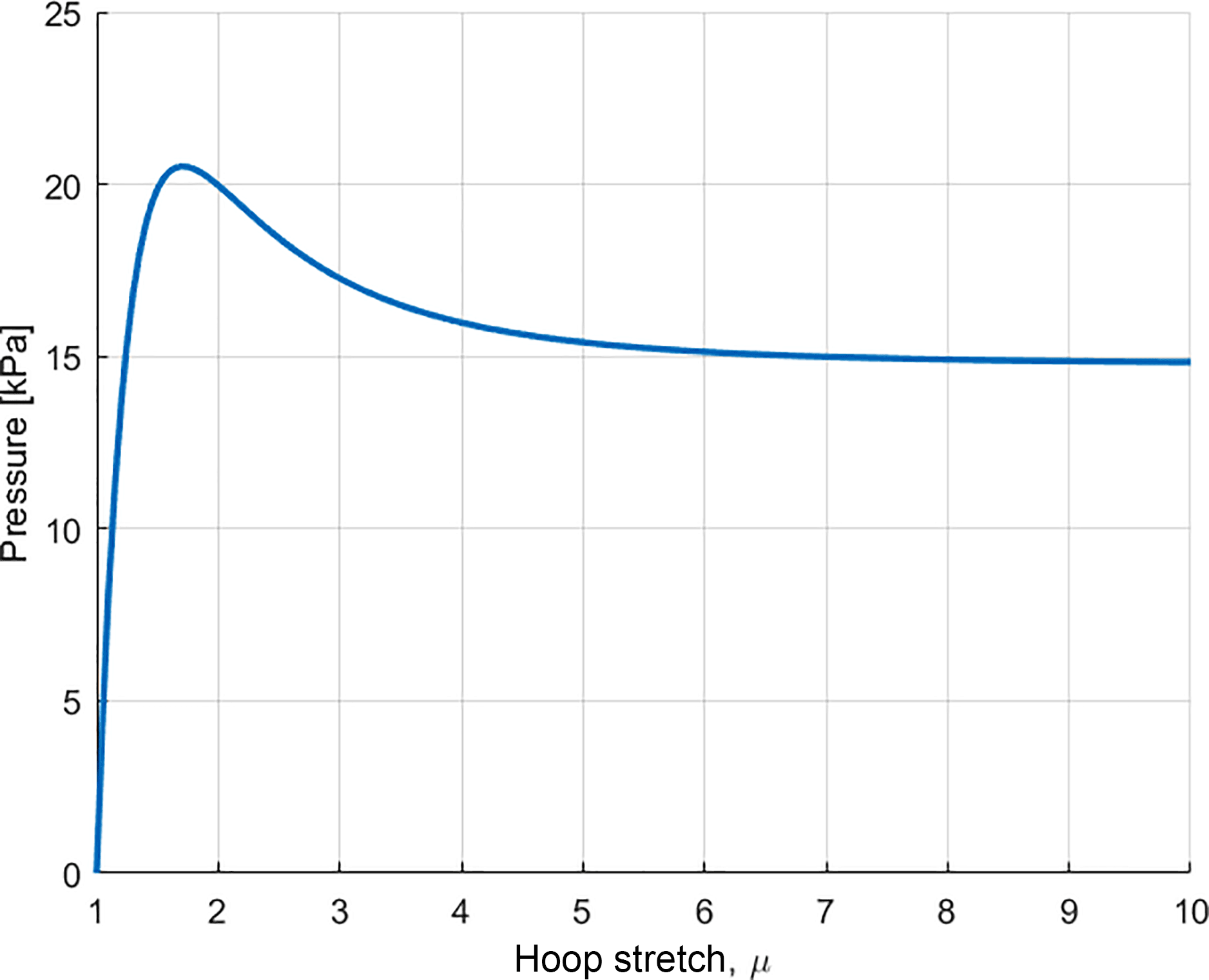
Also, pressure regarding the hoop stretch μ can be found as:
where K is minus the ratio of elasticity coefficients , ρ and ρ0 are the current and initial radii respectively, L and L0 are current and initial lengths and d0 is the wall thickness of the balloon (Müller and Strehlow, 2004).
In Fig. 4, pressure p(μ) from Eq. (2) is plotted with respect to µ. s+ and s− are taken as 3 and −0.3 bar, respectively; ρ0 is 0.32 cm and d0 is 0.025 cm. It is observed that pressure becomes independent of hoop stretch for large values of it. Initial peak at μ=1 occurs since the air that is first pumped in the balloon has to overcome both radial and axial stiffnesses. It is expected that pressure requirement will be less for maintaining the volume than for initial inflation.
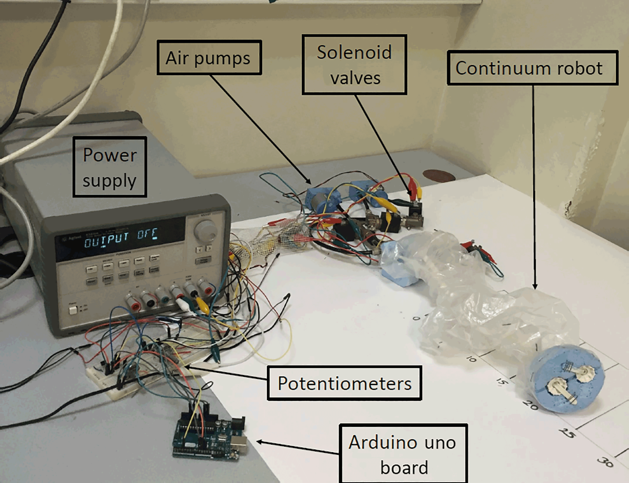
Following the conceptual design explained earlier, the continuum robot has been developed. The whole robotic system is shown in Fig. 5. Two extendable balloons are placed in a radially constricted and axially flexible shaft. The tip is made of polyurethane foam. The balloons used in this study are off-the-shelf Qualatex cylindrical balloons. A typical balloon has an uninflated initial length of 30 cm and a diameter of 4 mm. It is manufactured from natural rubber latex. Initially, the slack section remains outside of the tip, and the robot occupies approximately a 60 mm long space having a diameter of 50 mm (diameter of the tip). As the balloons are inflated, a continuous pushing force is generated at the back of the tip. Thus, the robot moves forward, and some amount of the slack section is ever so slightly retracted.
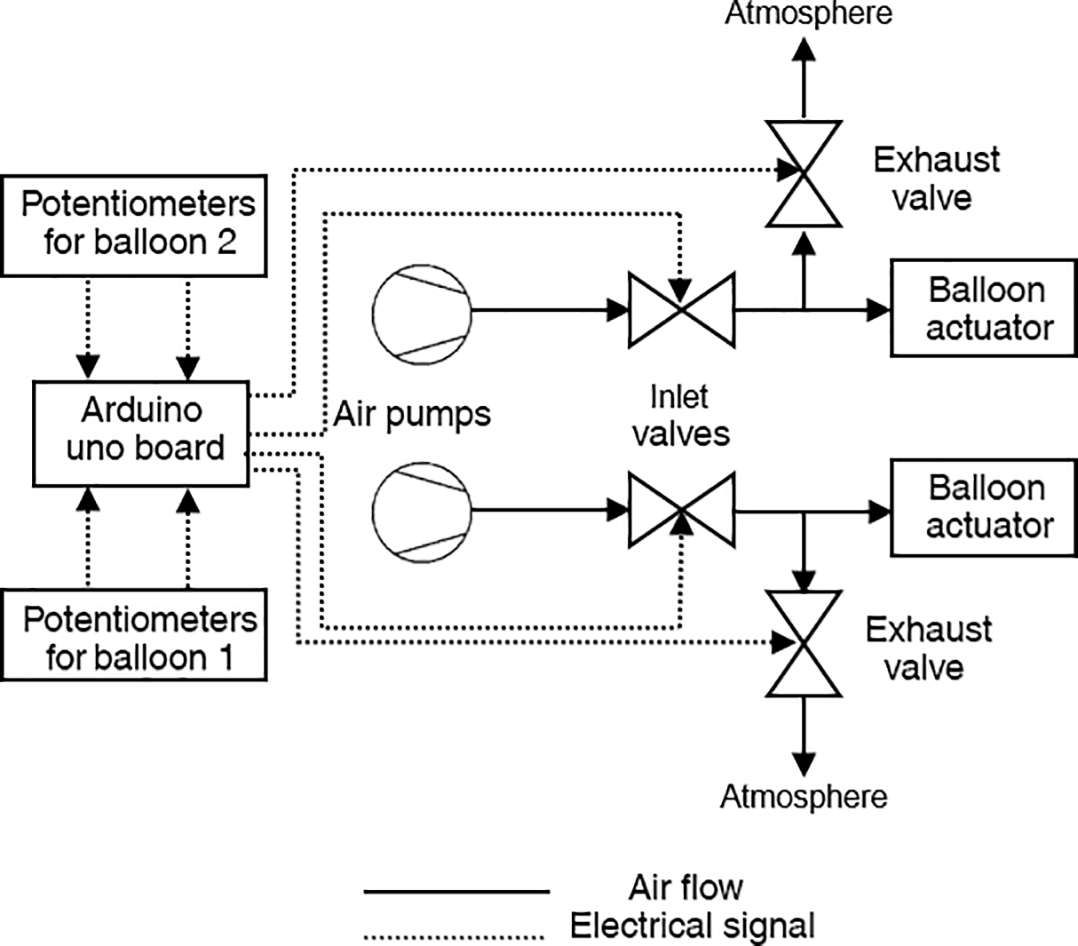
In order to control the air volume in the balloons the architecture given in Fig. 6 is used. Two air pumps (Parker BTC Diaphragm) and four two-way, normally closed solenoid valves (FG Line C1) are utilized. Pumps are operated at 18 V and valves are at 12 V DC. Two potentiometers are utilized as the user interface. Since the valves are able to work only on and off, valves are operated via Pulse Width Modulation (PWM) signals for speed control of inflation and deflation. PWM signals are generated by an Arduino Uno board at 1024 Hz. According to the value read from the potentiometers, each valve is assigned to one of three operating regions: on, on/off switching or off. In the on/off switching region, on and off times are controlled by pulse widths of PWM signals. Since the valves are not fast enough to track every pulse, for example very low duty cycles, their working region has been calibrated to ensure stable operation.
5.1 Balloon characterization
In order to characterize single balloon behavior, three experiments were performed. We performed these experiments to find the limits of the robot in terms of attainable maximum extension, highest speed, inlet pressure, and output force. First, elongations of seven individual balloons and their internal pressures were recorded while the balloons were inflated with the valves fully open (100 % duty cycle). Air pressures in the balloons were measured using a Setra C206 Pressure Transducer. For each balloon, elongation was recorded for five consecutive inflations and deflations in order to determine the differences of each balloon and inflation speeds, which will also correspond to the same characteristics of the robot. In this experiment, elongation is measured as the length of the inflated section of the balloon. This length can be considered as an effective length of the balloon since the tip is always at the end of the inflated section. As expected from Fig. 4, pressure peaks were observed during initial inflation. Since the change in radii of the balloons was not significant, they were measured manually and not tracked with a sensor. Any sensor on such a soft material would distort the stress state.
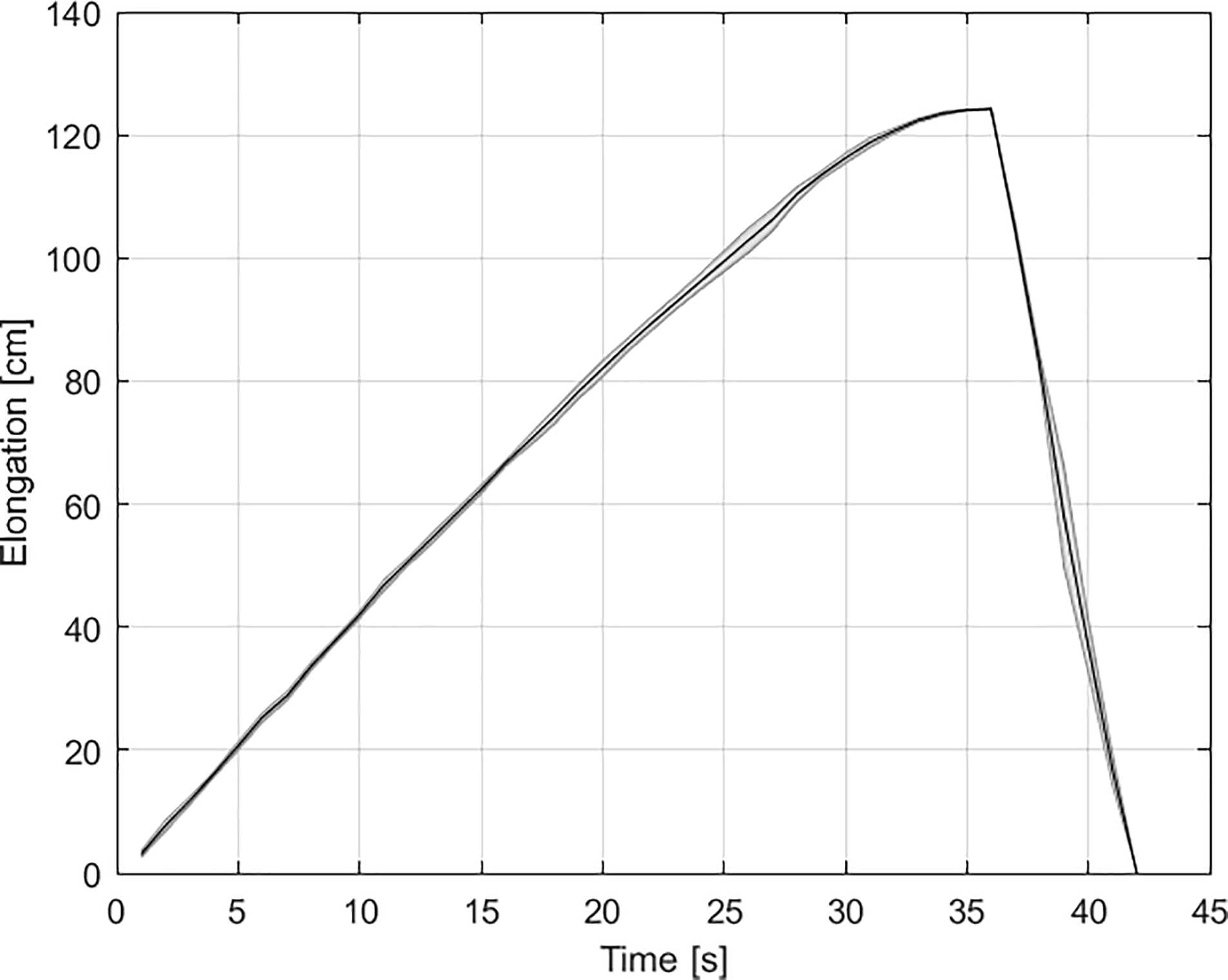
Figure 7Elongation behavior of the balloons for inflation and deflation. The solid line represents the mean elongation for seven balloons. The shaded area is the standard error of the mean.
Maximum elongations did not change much after second inflation. This behavior can be explained with the plasticity of the balloons. Their elasticities tend to converge in later inflations. During deflation, the positions tended to decrease almost at the same time. However, at the last stages of deflation, balloons sometimes went unstable as they had two local equilibrium points. This stability problem resulted in two inflated sections with a slack part in the middle. The same procedure was carried out for seven different balloons. The mean of last three repetitions was computed for each balloon. Then, the overall means and the standard errors of elongation for seven balloons were calculated. The mean values are plotted with respect to time in Fig. 7, where the standard error is represented as the shaded region. It was seen that the balloons expanded almost linearly. When they were close to full extension (i.e., when there was very little or no slack section left), their extending speed tended to decrease, and the extension was finally converged to a value of 124±6 cm. Deviation in this value can be explained by the differences in individual structural properties of a balloon as these local properties affect the inflation trend and the maximum length that a balloon can extend. Considering the linear regions in the inflation and deflation curves, average maximum speeds are about 3.8 and 21.0 cm s−1, respectively.
Second, in order to demonstrate the effects of different pulse widths on inflation behavior (i.e., inflation speed and pressure), a balloon was inflated with three different PWM signals; 33, 66 and 100 % duty cycles of the solenoid valves. These percentages are taken as the pulse width of the PWM signals corresponding to the highest and the lowest duty cycles that the valves can track. Since the air pumps are always operating, opening and closing of the valves are the only factors that affect the airflow into the balloons. In this analysis, the pressure was expected to remain constant after a peak. However, unlike shown in Fig. 4, pressure gradually increased as the balloon was inflated. This discrepancy is caused by the fact that the balloon is not a perfect, constant radius cylinder. The initial peak in pressure is observed because the first air that goes into the balloon has to overcome both the axial stress and the hoop stress of the rubber. Elongation and corresponding pressure values for a single balloon under different PWM signals are plotted in Fig. 8. It can be seen that speed of inflation decreased as lower duty cycles were employed. The inflation speeds are approximately 3.6, 3.2 and 2.34 cm s−1 for 100, 66, 33 % PWM, respectively. It is also observable that the maximum longitudinal strain decreases with lower duty cycles. Another observation is that the pressures of 33 and 66 % PWM cycles converge to almost the same value, even though there is an eight cm difference between the final elongations. This can be explained with the fact that more on-time of the valves enable the balloon to keep more air in, hence extending a little bit more.
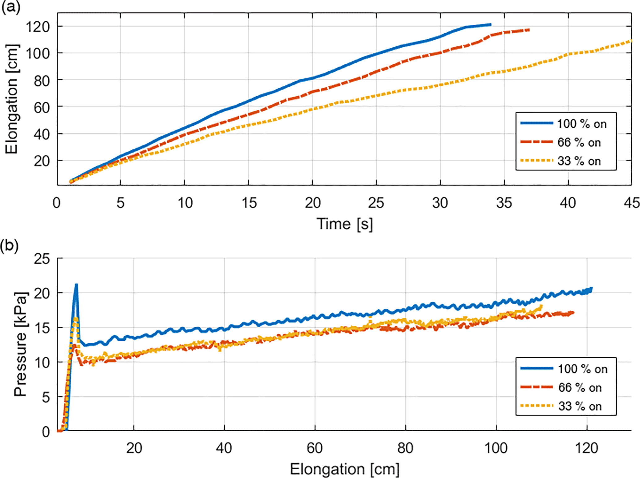
Figure 8Elongation (a) and the pressure vs. elongation (b) of a single balloon inflated with three different duty cycles of the solenoid valves.
Third, force that a balloon can apply in the axial direction was measured by an ATI Nano 17 force sensor while the balloon was constricting in a rigid cylindrical Plexiglas tube of length 1 m. The force sensor was located at the distal end of the tube. For these experiments, seven new balloons were tested. Each balloon was inflated while the valve was fully open, and force applied at the end, when the balloon was fully elongated, was measured for seven different balloons. The results are presented in Fig. 9. It is seen that force values increase at a decreasing rate after the balloons touch the force sensor. After some time, three of the balloons converged to a constant value of 5 N, two of them converged to 6.5 N. Assuming full contact with the force sensor, these force values correspond to a pressure value of 24.8±3.61 kPa. It should be noted that this pressure value is slightly higher than the one in free elongation. It can be deduced that the pressure builds up as the balloon is constricted in the tube before either the balloon explodes or comes to equilibrium with increased pressure where more leakage through the system is observed. Balloons 1 and 5 exploded, which can be seen as spikes and vertical drops in the measured forces. The balloons ruptured near the inlet where they were subjected to high strains.
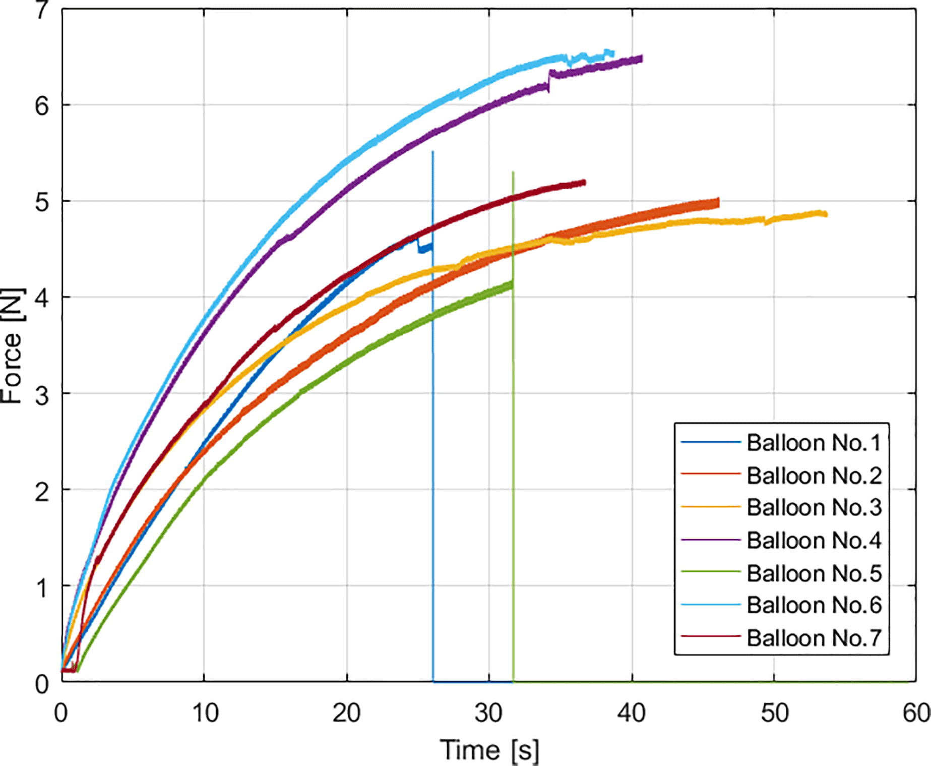
Figure 9Forces measured at the distal end of seven balloons constricted in a one meter long cylindrical tube.
5.2 Workspace
The reachable workspace of the robot is almost like an ellipse. The maximum length the robot can reach is almost 120 cm. This length is slightly shorter than the maximum length of the balloons because some of the slack section should be attached to the tip of the robot. Therefore, this section is never inflated. The minimum radius of curvature rmin is about 8 cm. However, this radius heavily depends on the initial curvature of the balloons utilized. Workspace of the robot is modeled in Fig. 10. An elliptic shape is obtained because the balloons are not externally constricted by an obstacle and radial constriction prevents a balloon from extending sideways just after initial inflation (when rmin is reached). Side-to-side width of the reachable workspace is about 60 cm.
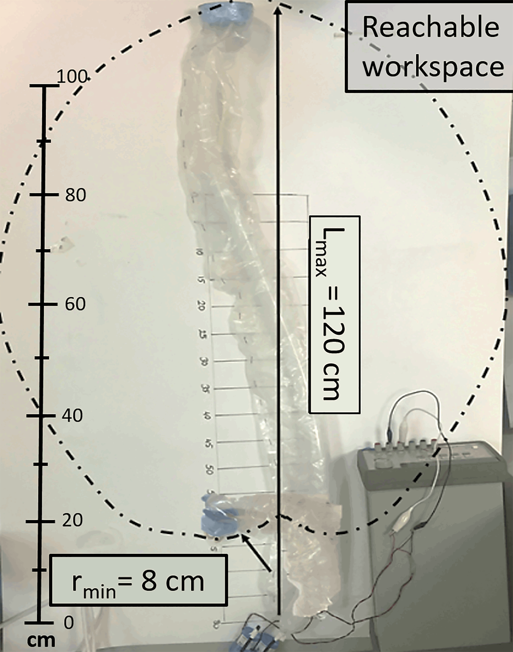
Figure 10Reachable workspace, maximum reach and minimum radius of curvature of the robot. Side-to-side width of the reachable workspace is about 60 cm.
5.3 Navigation experiments
Two sets of navigation experiments have been conducted as follows. In both of these experiments, the speed of inflation of the balloons was controlled manually by an operator (the first author) via potentiometers.
5.3.1 Open field navigation
In this experiment, the robot was navigated in an open environment without any obstacles. First, the balloons were inflated together to make the robot go straight. Some rotations due to the structure of the balloons were encountered, but they were corrected by inflating the balloon on the same side as the curvature. Then, the robot was navigated to both sides by inflating a balloon more than the other. Straight-line movement and turning right are demonstrated in Figs. 11 and 12. Turning to left is almost identical to what is shown in Fig. 12. All trials were successful in open field navigation.

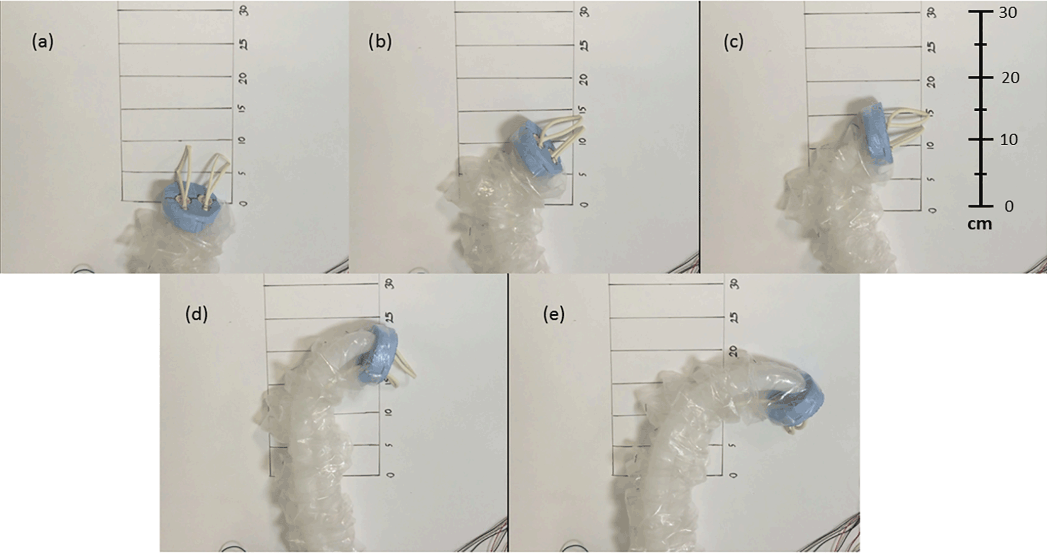
Figure 12Robot turning to the right by inflating one balloon more than the other. Numbers are in cm.
5.3.2 Maze navigation
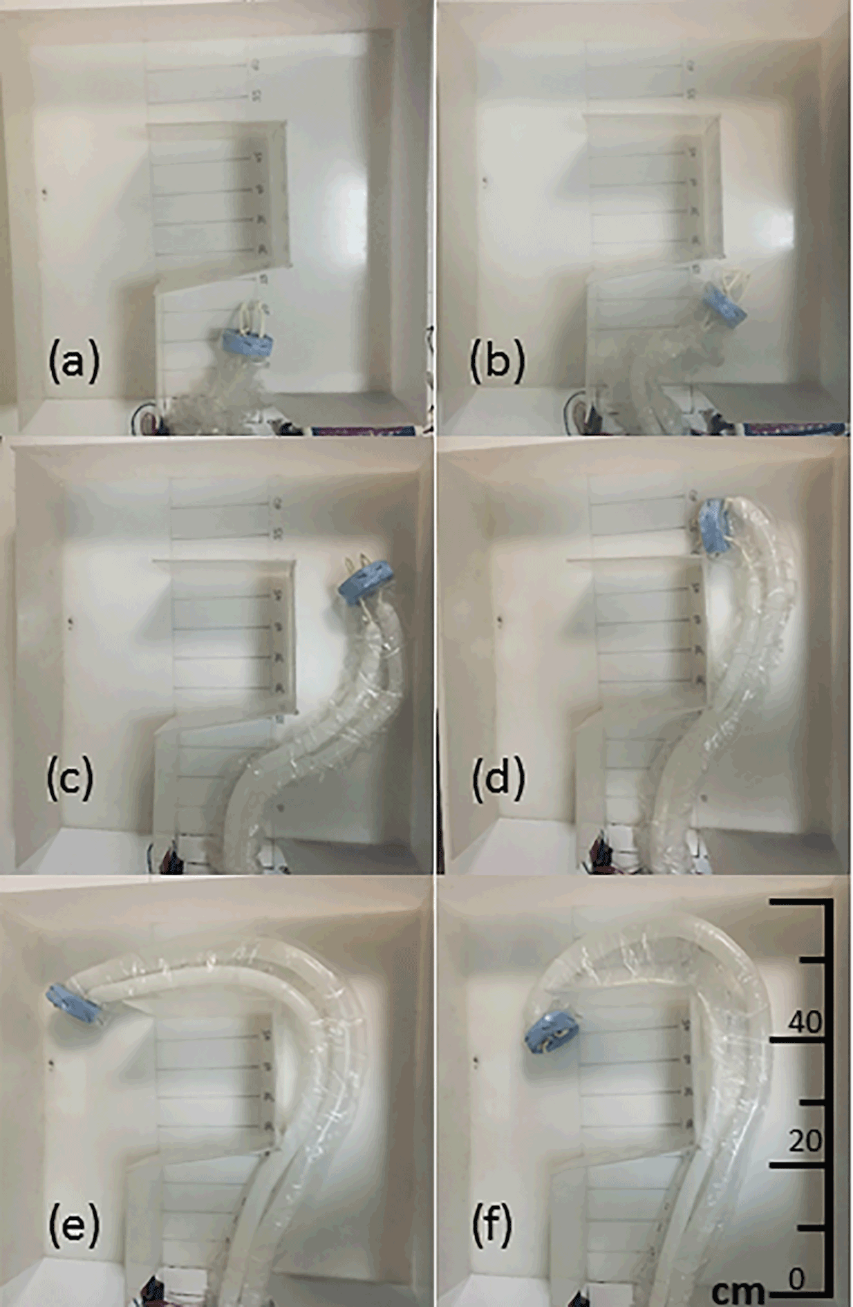
In this test, the robot was navigated through a predesigned, maze-like environment to reach a goal position in the middle of the maze. Maze walls were cut from 5 mm thick Plexiglas. The robot was placed in its initial position and guided through the maze using potentiometers that control the airflow rate into each balloon. The process of reaching goal position is demonstrated in Fig. 13. In Fig. 13a and b, the left hand side balloon was inflated more than the other one so that the robot could rotate rightwards. When the configuration shown in Fig. 13c was reached, the balloon on the right was inflated more. However, since it was a tight corner, the balloon on the left was slightly deflated (Fig. 13d). The same operation was performed in the configuration shown in Fig. 13e and f as well.
Results of the balloon characterization experiments showed the capabilities of the actuation system of the continuum robot. The continuum robot can extend to 1200 mm from its most contracted form which is 60 mm. This corresponds to an extension of 2000 % which is much higher than the largest strain reported in the literature (300 %) by Hawkes et al. (2016). The robot is also is able to achieve its extreme lengths quickly. When the valves are fully open, the inflation speed is about 3.8 cm s−1 and the deflation speed is around 21 cm s−1.
It is necessary to remark that five balloons ruptured during elongation experiments. Results of these balloons are omitted and hence not included in the analysis. Since the balloons expand only from the distal end when pressurized, the greatest amount of reaction forces arises upon contact of the tip with an obstacle. In transverse directions, the balloons are highly compliant. Therefore, axial forces are the only source of effort for the continuum robot. Determining the force capabilities of the robot with respect to the input pressures is important, as they may be used to develop a better output force control method. Thus, the robot can be adapted to different manipulation tasks. Forces that can be applied by each balloon are different due to individual structures of the balloons. However, a value of 4 N can be assumed as a threshold that which a random balloon may explode if more force is applied. For different materials and different sized balloons, force-generating capability can be altered. However, such low values were expected since the balloons, therefore the robot, have no rigid backbone. This robot can be suitable for applications where the objective is to reach a goal position and carry out tasks there with auxiliary devices that would be attached to the tip.
The navigation tests showed that the robot was successfully controlled in open field and a maze. When the robot was navigated in open field, following a perfectly straight line was impossible since the balloons had an unpredictable slight curvature because of their structure. This is also related to the manual control of the airflow rates to the balloons and heavily depends on the skills of the operator. If one or both of the balloons have a curvature, the deviation from a straight line is immediately observable. The operator, however, could easily correct this deviation by changing the inflation speeds of each balloon. Another problem that was encountered in the navigation tests that the radius of rotation was different when the robot was rotated due to the wrinkled structure of the outer sheath. A final remark is about shortening and re-elongation of the robot. Although elasticity of the balloons brings the tip of the robot back while the balloons are deflated, the robot will not be able to return to its initial, the most compact form without some kind of mechanism to retract the slack outside of the tip.
The proposed continuum robot serves as a proof-of-concept for a novel way of pneumatic actuation enabling it to be navigated through delicate and unstructured environments. Further research may see this kind of actuation system to be employed in applications such as for exploratory (Majidi, 2014; Tolley et al., 2014) or medical purposes (Cianchetti et al., 2014) if higher quality balloon actuators are used. The proposed design is able to tolerate much higher longitudinal strains than the examples in the literature (Hawkes et al., 2016), and is maneuvered with less pressure than the stiffer designs (Sun et al., 2016). Please note that growth-based soft robots, such as the very-recent example called vine robots (Hawkes et al., 2017), can lengthen by thousands of percent from the tip, too. Although the actuation principles are different, these robots serve to the same purpose.
The developed robot inherits some of the common disadvantages of continuum robots such as; modeling difficulties, low force generation capabilities, controllability issues, the need for bulky external pressure regulation equipment, and unpredictability and steady-state positioning errors in control due to their flexible nature (Penning and Zinn, 2014). Further research on these aspects may help to tackle mentioned problems and enhance the performance of the proposed actuation system. Instead of employing off-the-shelf balloons, an advanced and homogeneous polymer can be utilized to increase predictability of actuation characteristics. Manufacturing balloon actuators in an application-specific manner may also allow us to tailor balloon actuators such that the robot can be optimized for the application in mind. The shaft design can be improved too, enabling the balloons to be constricted more tightly to provide better control. If a more advanced material is used, it can enhance the controllability and predictability of the robot. Moreover, the inflation process is not completely reversible. The balloons can be deflated for some amount. But if it is too much, the slack section remains behind the tip and it becomes impossible to precisely control the robot. A mechanism to be located at the tip of the robot may enable recoiling of the slack of the balloons, thus making the inflation process completely reversible. Finally, some stiffening mechanism can be added to the shaft like jamming (Cheng et al., 2012) to introduce load bearing capability and robot may be made to bare transversal loads as well as the axial loads.
In this study, we have proposed a novel continuum robot actuated by two extendable balloons and preliminary characterization experiments were performed. Motion characteristics of extendable balloons were theoretically calculated and experimentally verified. The robotic system as a whole was evaluated in terms of its navigation capabilities in open field and a maze. The experimental results showed that the performance and capabilities of the proposed system under different circumstances satisfy our navigation expectations. Utilizing extendable balloons as pneumatic actuators, enables the robot to have much more longitudinal strain than the examples found in the literature. The continuum robot proposed in this study can elongate to twenty times more in length from its initial controllable position. This corresponds to a very high extension of 2000 %. Since the backbone of the robot is guided by obstacles in the workspace, it conforms to the obstacles and is able to reach a goal position rapidly, especially in substantially long and narrow environments. Proposed actuation system looks promising and may be utilized in applications such as medical endoscopy. Further research is underway to develop a robotic colonoscopy device at our laboratory.
All the data and MATLAB codes can be found in a GitHub repository. Every result presented in this paper is reproducible. The link is as follows: https://github.com/eyyarbasi/ContinuumRobot.
The authors declare that they have no conflict of interest.
This work was supported by the Scientific and Technological Research Council
of Turkey (TUBITAK, # 115E717).
Edited by: Chin-Hsing Kuo
Reviewed by: Yigit Menguc and one anonymous referee
Bishop-Moser, J., Krishnan, G., Kim, C., and Kota, S.: Design of soft robotic actuators using fluid-filled fiber-reinforced elastomeric enclosures in parallel combinations, in: IEEE International Conference on Intelligent Robots and Systems, Vilamoura, Portugal, 7–12 October 2012, 4264–4269, https://doi.org/10.1109/IROS.2012.6385966, 2012.
Calisti, M., Giorelli, M., Levy, G., Mazzolai, B., Hochner, B., Laschi, C., and Dario, P.: An octopus-bioinspired solution to movement and manipulation for soft robots, Bioinspir. Biomim., 6, 36002, https://doi.org/10.1088/1748-3182/6/3/036002, 2011.
Cheng, N. G., Lobovsky, M. B., Keating, S. J., Setapen, A. M., Gero, K. I., Hosoi, A. E., and Iagnemma, K. D.: Design and analysis of a robust, low-cost, highly articulated manipulator enabled by jamming of granular media, in Proceedings – IEEE International Conference on Robotics and Automation, Saint Paul, MN, USA, 14–18 May 2012, 4328–4333, 2012.
Chirikjian, G. S. and Burdick, J. W.: An obstacle avoidance algorithm for hyper-redundant manipulators, in IEEE International Conference on Robotics and Automation, Cincinnati, OH, USA, 13–18 May 1990, 625–631, 1990.
Chirikjian, G. S. and Burdick, J. W.: A hyper-redundant manipulator, IEEE Robot. Autom. Mag., 1, 22–29, https://doi.org/10.1109/100.388263, 1994.
Chou, C. P. and Hannaford, B.: Measurement and modeling of McKibben pneumatic artificial muscles, IEEE Trans. Robot. Autom., 12, 90–102, https://doi.org/10.1109/70.481753, 1996.
Cianchetti, M., Ranzani, T., Gerboni, G., Nanayakkara, T., Althoefer, K., Dasgupta, P., and Menciassi, A.: Soft robotics technologies to address shortcomings in today's minimally invasive surgery: the STIFF-FLOP approach, Soft Robot., 1, 122–131, https://doi.org/10.1089/soro.2014.0001, 2014.
Cianchetti, M., Calisti, M., Margheri, L., Kuba, M., and Laschi, C.: Bioinspired locomotion and grasping in water: the soft eight-arm OCTOPUS robot, Bioinspir. Biomim., 10, 35003, https://doi.org/10.1088/1748-3190/10/3/035003, 2015.
Conrad, B. and Zinn, M.: Closed Loop Task Space Control of an Interleaved Continuum – Rigid Manipulator, in IEEE International Conference on Robotics and Automation, Seattle, WA, 1743–1750, 2015.
Follador, M., Cianchetti, M., and Laschi, C.: Development of the functional unit of a completely soft octopus-like robotic arm, in: 2012 4th IEEE RAS and EMBS International Conference on Biomedical Robotics and Biomechatronics (BioRob), IEEE, 24–27 June 2012, Rome, Italy, 640–645, 2012.
Godage, I. S., Medrano-Cerda, G. A., Branson, D. T., Guglielmino, E., and Caldwell, D. G.: Dynamics for variable length multisection continuum arms, Int. J. Robot. Res., 35, 695–722, https://doi.org/10.1177/0278364915596450, 2016.
Grossard, M., Chaillet, N., and Regnier, S.: Flexible Robotics, John Wiley & Sons, Inc., London, UK, 349–379, 2013.
Hawkes, E. W., Christensen, D. L., and Okamura, A. M.: Design and implementation of a 300 % strain soft artificial muscle, in: 2016 IEEE International Conference on Robotics and Automation (ICRA), IEEE, 16–21 May 2016, Stockholm, Sweden, 4022–4029, 2016.
Hawkes, E. W., Blumenschein, L. H., Greer, J. D., and Okamura, A. M.: A soft robot that navigates its environment through growth, Sci. Robot., 2, eaan3028, https://doi.org/10.1126/scirobotics.aan3028, 2017.
Kang, R., Branson, D. T., Zheng, T., Guglielmino, E., and Caldwell, D. G.: Design, modeling and control of a pneumatically actuated manipulator inspired by biological continuum structures, Bioinspir. Biomim., 8, 036008, https://doi.org/10.1088/1748-3182/8/3/036008, 2013.
Katz, D., Pyuro, Y., and Brock, O.: Learning to Manipulate Articulated Objects in Unstructured Environments Using a Grounded Relational Representation, Proceedings of Robotics: Science and Systems IV, ETH Zurich, Switzerland, 25–28 June 2008, https://doi.org/10.15607/RSS.2008.IV.033, 2008.
Katzschmann, R. K., Marchese, A. D., and Rus, D.: Autonomous object manipulation using a soft planar grasping manipulator, Soft Robot., 2, 155–164, https://doi.org/10.1089/soro.2015.0013, 2015.
Kier, W. M. and Smith, K. K.: Tongues, tentacles and trunks: the biomechanics of movement in muscular-hydrostats, Zool. J. Linn. Soc.-Lond., 83, 307-324, 1985.
Laschi, C., Cianchetti, M., Mazzolai, B., Margheri, L., Follador, M., and Dario, P.: Soft robot arm inspired by the octopus, Adv. Robotics., 26, 709–727, https://doi.org/10.1163/156855312X626343, 2012.
Laschi, C., Mazzolai, B., and Cianchetti, M.: Soft robotics: Technologies and systems pushing the boundaries of robot abilities, Sci. Robot., 1, eaah3690, https://doi.org/10.1126/scirobotics.aah3690, 2016.
Majidi, C.: Soft robotics: a perspective – current trends and prospects for the future, Soft Robot., 1, 5–11, https://doi.org/10.1089/soro.2013.0001, 2014.
Marchese, A. D., Tedrake, R., and Rus, D.: Dynamics and trajectory optimization for a soft spatial fluidic elastomer manipulator, Int. J. Rob. Res., 35, 1000–1019, https://doi.org/10.1177/0278364915587926, 2016.
Moers, A. J. M., De Volder, M. F. L., and Reynaerts, D.: Integrated high pressure microhydraulic actuation and control for surgical instruments, Biomed. Microdevices, 14, 699–708, https://doi.org/10.1007/s10544-012-9650-y, 2012.
Müller, I. and Strehlow, P.: Rubber and Rubber Balloons: Paradigms of Thermodynamics, Springer-Verlag, Berlin, Germany, 2004.
Penning, R. S. and Zinn, M. R.: A combined modal-joint space control approach for continuum manipulators, Adv. Robotics., 28, 1091–1108, https://doi.org/10.1080/01691864.2014.913503, 2014.
Ranzani, T., Gerboni, G., Cianchetti, M., and Menciassi, A.: A bioinspired soft manipulator for minimally invasive surgery, Bioinspir. Biomim., 10, 35008, https://doi.org/10.1088/1748-3190/10/3/035008, 2015.
Robinson, G. and Davies, J. B. C.: Continuum robots – a state of the art, in: IEEE International Conference on Robotics and Automation, 10–15 May 1999, Detroit, MI, 4, 2849–2854, 1999.
Rus, D. and Tolley, M. T.: Design, fabrication and control of soft robots, Nature, 521, 467–475, https://doi.org/10.1038/nature14543, 2015.
Sun, Y., Song, S., Liang, X. and Ren, H.: A Miniature Soft Robotic Manipulator Based on Novel Fabrication Methods, IEEE Robot. Autom. Lett., 1, 617–623, https://doi.org/10.1109/LRA.2016.2521889, 2016.
Swaney, P. J., Mahoney, A. W., Remirez, A. A., Lamers, E., Hartley, B. I., Feins, R. H., Alterovitz, R. and Webster, R. J.: Tendons, concentric tubes, and a bevel tip: Three steerable robots in one transoral lung access system, in Proceedings – IEEE International Conference on Robotics and Automation, vol. 2015-June, Seattle, WA, USA, 5378–5383, 2015.
Tolley, M. T., Shepherd, R. F., Mosadegh, B., Galloway, K. C., Wehner, M., Karpelson, M., Wood, R. J., and Whitesides, G. M.: A resilient, untethered soft robot, Soft Robot., 1, 213–223, https://doi.org/10.1089/soro.2014.0008, 2014.
Tonapi, M. M., Godage, I. S., Vijaykumar, A. M., and Walker, I. D.: A novel continuum robotic cable aimed at applications in space, Adv. Robotics., 29, 861–875, https://doi.org/10.1080/01691864.2015.1036772, 2015.
Walker, I. D.: Continuous backbone “continuum” robot manipulators, ISRN Robot., 2013, 1–19, https://doi.org/10.5402/2013/726506, 2013.
Yarbasi, E. Y.: Design and Evaluation of a Continuum Robot with Extendable Balloons, MS thesis, Bogazici University, Istanbul, Turkey, 2016.