the Creative Commons Attribution 4.0 License.
the Creative Commons Attribution 4.0 License.
 | 08 Nov 2018
A new manual wheelchair propulsion system with self-locking capability on ramps
Gaspar Rodríguez Jiménez
David Rodríguez Salgado
Francisco Javier Alonso
José María del Castillo
A wheelchair user faces many difficulties in their everyday attempts to use ramps, especially those of some length. The present work describes the design and build of a propulsion system for manual wheelchairs for use in ascending or descending long ramps. The design is characterized by a self-locking mechanism that activates automatically to brake the chair when the user stops pushing. The system consists of a planetary transmission with a self-locking capacity coupled to a push rim with which the user moves the system. Different transmission ratios are proposed, adapted to the slope and to the user's physical capacity (measured as the power the user can apply over ample time periods). The design is shown to be viable in terms of resistance, and approximate dimensions are established for the height and width of the propulsion system. Also, a prototype was built in order to test the self-locking system on ramps.
- Article
(8177 KB) - Full-text XML
- BibTeX
- EndNote


There are several types of manual wheelchairs, among which there stands out the basic manual push rim propelled models (Vanlandewijck et al., 2001; van der Woude et al., 2001). These account for around 90 % of the chairs existing on the market. They are the most commonly used due to their low cost, their excellent handling capacity, and ease of transportation since they can be folded (van der Woude et al., 2006). Another type that stands out is the crank-propelled wheelchair. This uses the same type of propulsion as bicycles and its most efficient configuration is that of handcycling, where propulsion is powered using the hands (Arnet et al., 2013). Another type is the lever-propelled wheelchair which uses a lever fixed directly to the rim, allowing the user to adopt a more ergonomic position and being more efficient than the crank-propelled wheelchair (van der Woude et al., 2001). The last type of chair with manual propulsion is the geared manual wheelchair which functions with mechanical geared wheels (Flemmer and Flemmer, 2016).
Ramps are a major problem for users' everyday lives. This is especially so for the long ramps that they encounter in cities, since activities that require changes of inertia need more upper limb strength than those needed to maintain speed on the flat (Sonenblum et al., 2012).
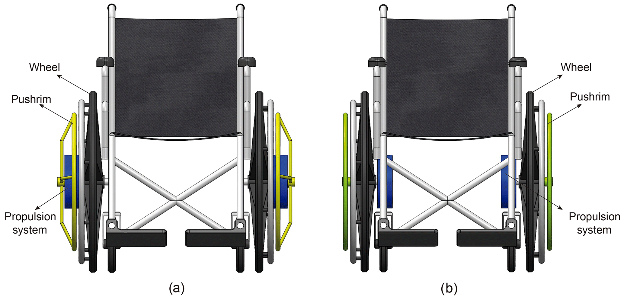
Figure 1Different arrangements of the propulsion system: (a) between the wheel and the power input element; (b) under the seat.
There are some devices in the literature that allow the users to use geared transmissions for manual wheelchairs propulsion but not many of them complement the propulsion with a locking mechanism when ascending or descending a ramp. Magicwheels is a commercial brand (Meginniss and SanFrancisco, 2006) that uses a transmission based on a hypocycloidal which has two modes. In the standard mode the hand rim is connected directly to the wheel and the system behaves like a normal pushrim propelled wheelchair. If the user pushes a shift on the hub, the gear turns into a transmission providing a gear ratio lower than 1:1 which helps wheelchair users to ascend a ramp easily. It also has a hill holding mechanism which prevents the wheelchair from rolling backwards. This hill holder mechanism includes one way roller assemblies in order to rotate in one direction but not the other. Thus, the locking of the mechanism is achieved through friction preventing the gear assembly from moving backwards. The device is mounted on a wheel, and the user would replace its own wheel in order to use this propulsion system.
In this work, a propulsion system is proposed whose main component is a wheel-locking system based on a self-locking planetary gear train (PGT) that can be attached to any manual wheelchair. Since the self-locking PGT is a mechanism in which the input and output are coaxial, it can be feasibly coupled to any wheelchair. The input of the mechanism is connected to push rims through which the user can apply power to the propulsion system, and this then transmits the movement to the chair. However, if the power is transmitted from the wheels themselves (which are connected to the output of the mechanism), the system does not allow movement due to its self-locking nature. The system is ideal for long ramps, where its use helps reduce the effort needed over a long period of time, preventing the user becoming fatigued, and allowing them to ascend or descend a long slope.
In the following sections, we shall describe firstly the possible arrangements and transmission ratios of the propulsion system that are required to climb ramps of different slopes, based on different power inputs. Then, a proposed design of the self-locking system and details of the propulsion system will be described. Finally, a functional and qualitative evaluation of the prototype will be tested on a ramp.
The main element of the propulsion is a PGT. This is a coaxial transmission with a single degree of freedom, so that it has to have a fixed member to operate correctly but can be attached to any wheelchair. In particular, the system can be implemented directly between the wheel and the power transmission element (the push rim) as shown in Fig. 1a, or under the chair with a different configuration as shown in Fig. 1b. This latter is the option chosen for the present work.
The need to have a mechanism with one degree of freedom requires one of the elements of the system to be established as a fixed member (ω=0). For this reason, the housing containing the propulsion system is fixed to the chassis of the wheelchair. To explain the behaviour of the propulsion system, Fig. 2 shows the two situations that can occur when a manual wheelchair user is on a ramp. In Fig. 2a, the power input is from the push rim. In this case, the mechanism is capable of transmitting power and thus moving the wheel. However, when the power input is through the wheel, i.e., when the user is not moving the push rim, the configuration of the system prevents power being transmitted to the output member, and the movement of the chair is locked, as is shown in Fig. 2b.
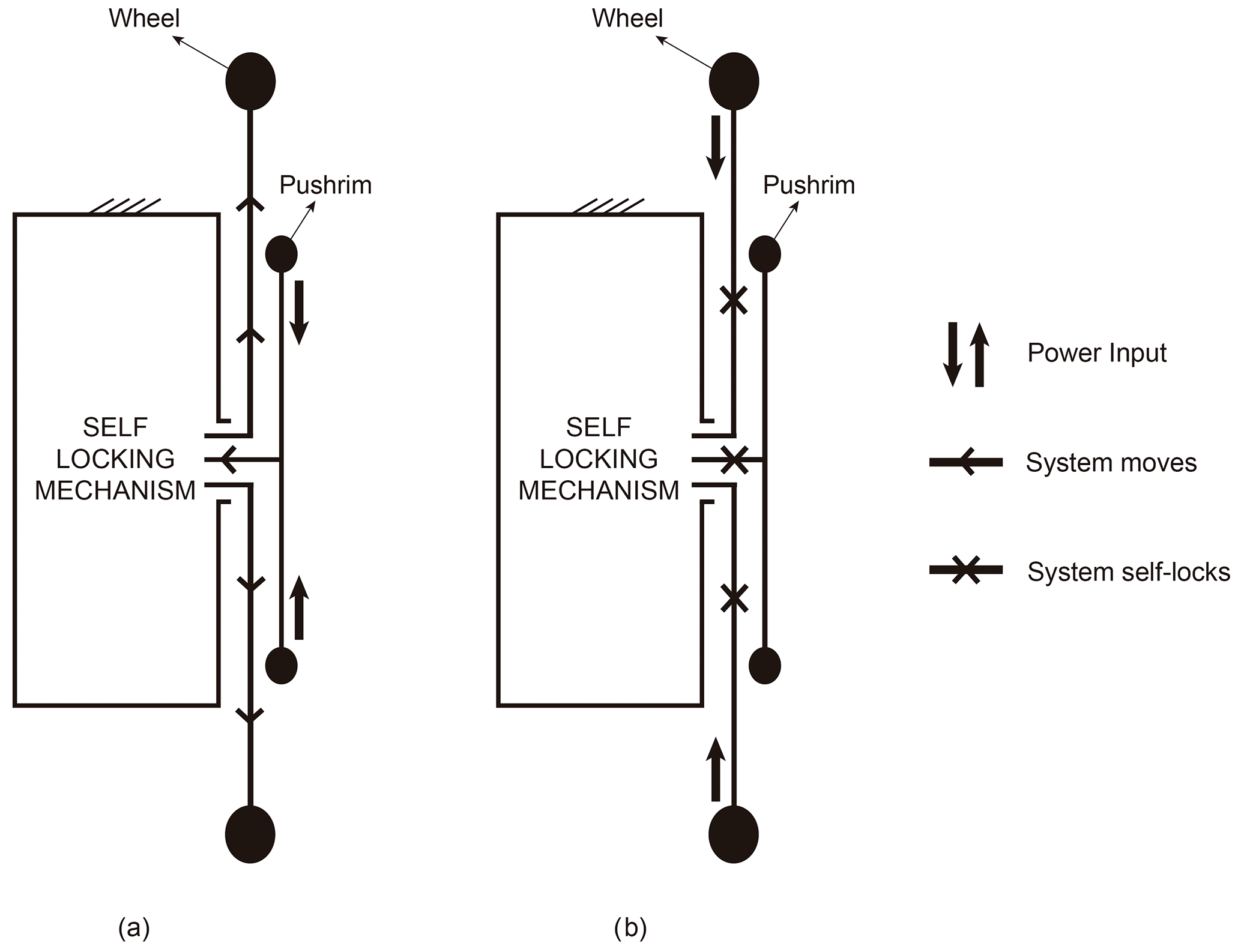
Figure 2Action of the propulsion system when: (a) power is input through the push rim (the propulsion system functions); (b) power is input through the wheels (the propulsion system has self-locked).
Thus, with this system, the user can resume propelling the chair at will without needing to activate or deactivate any wheel locking mechanism. Also, the effects of inertia when the user is on a ramp do not have to be overcome since the mechanism locks when power input is through the wheels. The same is the case when motion is resumed, i.e., it is not necessary to overcome the effects of inertia when power is input through the push rim.
There are various factors that influence the manual propulsion of a wheelchair, such as the type of surface on which the chair is being propelled (Koontz et al., 2005), the individual's mass (Sprigle and Huang, 2015), and the slope of the terrain (Choi et al., 2015). Upper trunk activity increases as the slope becomes steeper, but the use of any reduction mechanism that increases the torque applied to the axis of the chair decreases the performance of certain muscle groups of the user's upper trunk (Howarth et al., 2010). Figure 3 shows the forces on the propulsion wheel when the user is on a slope, assuming that the chair moves with constant speed.
In this figure Fdrag is the rolling resistance force, α is the slope of the ramp, Ft(α>0) is the tangential force the subject needs to apply to move the chair when α>0, and ϕ is the angle with the horizontal formed by the radius to the point of application of the tangential force. This force causes the propulsion torque at the centre of the wheel. It can be seen that the total force is with the purely tangential force Ft(α>0) being responsible for the forward movement of the wheelchair (Boninger et al., 1997, 2002; Chow et al., 2009; Dallmeijer et al., 1994; De Groot et al., 2002; Kwarciak et al., 2009; Lin et al., 2009; Robertson et al., 1996; Veeger et al., 1991; van der Woude et al., 1988), and Fr being the normal component which, although it does not move the chair, plays a part in the friction between the hand and the push rim.
We make the following simplifying assumptions in this work: the analysis is done in two dimensions (van der Woude et al., 1988); the speed of ascent (vslope=cte) (Arnet et al., 2013; Chow et al., 2009; Veeger et al., 1991; Van Der Woude et al., 2003); the inertia of the wheel (Richter et al., 2007; van der Woude et al., 1988) and the aerodynamic resistance (Van Der Woude et al., 2003, 1988) are neglected; and the forces the user applies to each wheel are symmetrical (Arnet et al., 2013). Then:
Given Ft(α>0) one can determine the torque needed to move the chair up a ramp. Taking a total mass (chair + user) of m=100 kg and a coefficient of rolling resistance ρ=0.015 in accordance with the results reported in de Groot et al. (2006) and Richter et al. (2007), one has:
Where rp is the radius of the pushrim, which we take 0.225 m. The power input PI applied directly to the pushrim is given by:
Where is the angular velocity in rad s−1 of the wheels on the slope, with rw being the radius of the wheel which we take rw=0.27 m.
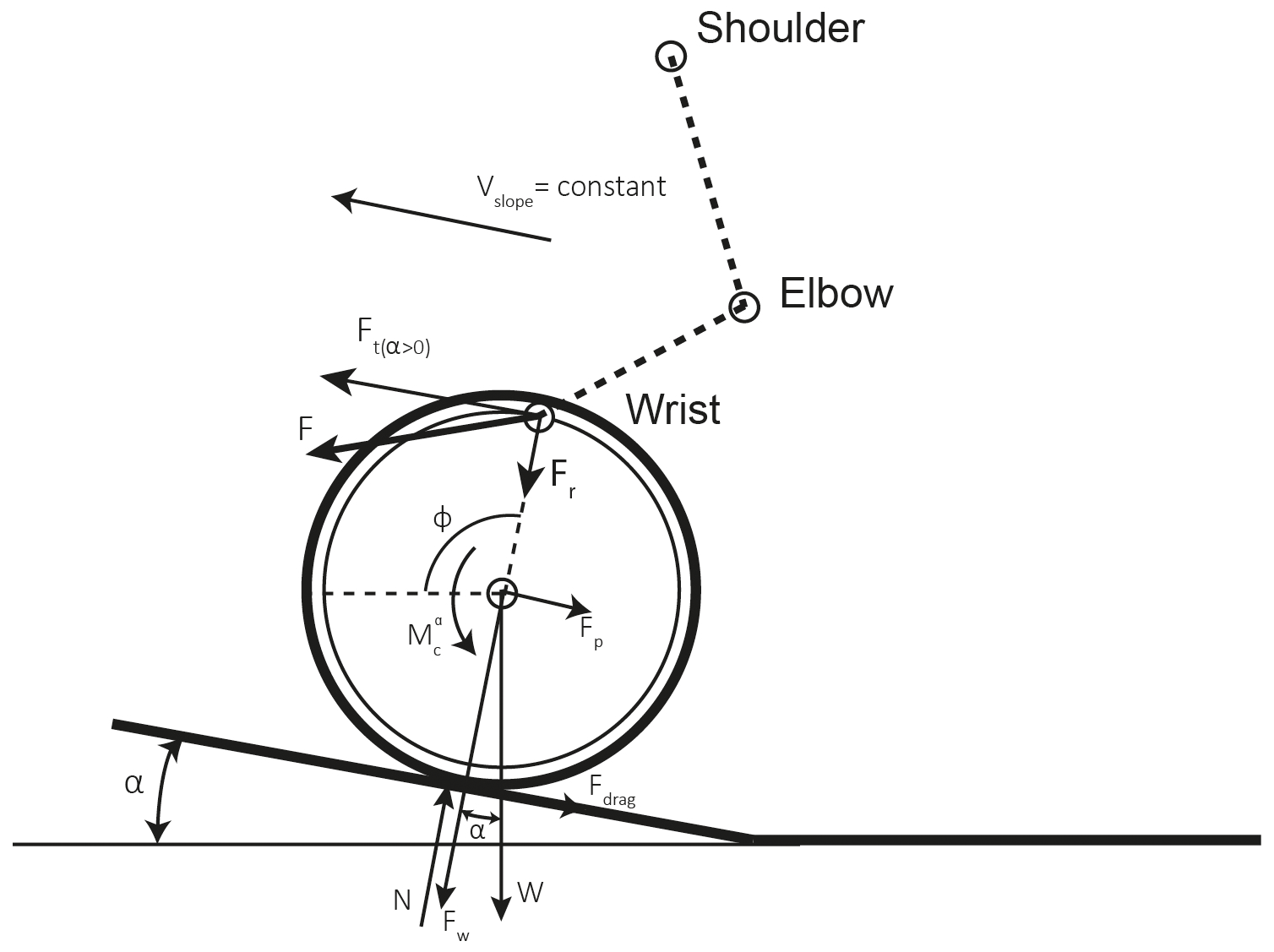
Figure 3The forces and torques on the push rim of the wheelchair when climbing a slope at constant speed.
In this work, we took an individual's physical condition to be the power that they can input at a constant rate for an ample period of time. In Salgado and Castillo (2007), it is explained that for a planetary propulsion system to be self-locking, it must be designed in such a way that the mechanism is one of reduction. In this sense, the propulsion system's transmission ratio (Rt) is obtained as a function of PI and the slope to ascend. To calculate vslope, we set vl=1.2 m s−1 which is the speed that the chair would have on the flat without using the propulsion system, and then vslope=Rtvl.
Figure 4 shows power input to the push rim for different values of vslope (with Rt being 1∕12, 1∕6, 1∕4, 1∕3 and 5∕12) for vl=1.2 m s−1. For this study, we considered that ramp slopes of less than 4 % are too little, and greater than 10 % are too steep, for the propulsion system to be used. The suitable values are represented by a shaded area in Fig. 4 and, while it is not a criterion for the choice of the propulsion system, it does establish an approximation of the minimum and maximum ramps that a user can take on. The figure represents by way of example a user whose physical capacity allows them to input PI=50 W at the push rim. Depending on the slope to ascend, one obtains the corresponding values of Rt represented by the points (P1, P2, P3, P4). With the same PI, the user is able to climb ramps ranging from 4.7% at a speed of vslope=0.5 m s−1 to 13.7 % at a speed of vslope=0.2 m s−1. This graphic thus makes it possible to clearly see the values of Rt the user will need to climb certain ramps depending on the PI they are capable of.
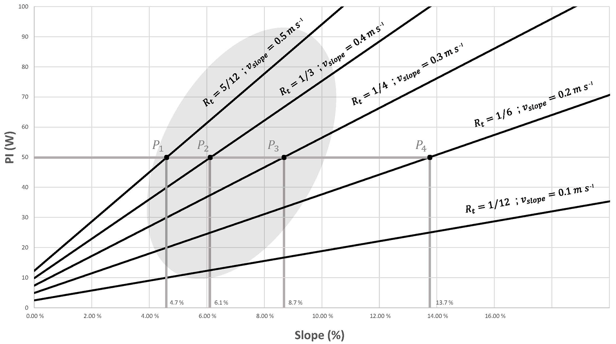
Figure 4Diagram of the transmission ratios Rt and speed of climb for a given vl=12 m s−1 as functions of the slope to ascend and the power PI that the user inputs to the chair.
The behaviour of the propulsion system was verified by a simulation in which a user wishes to climb a ramp of approximately 5 % slope and is capable of inputting a power PI=50 W for a long period of time. Taking vl=1.2 m s−1 as in Fig. 4, one can see that these data correspond approximately to the point P1, with , i.e., vslope=0.5 m s−1. Figure 5 shows the user performing a complete push cycle while climbing a ramp. When the user stops inputting power, the system locks (Fig. 5b). When, at any time, the user wishes to resume the ascent they can do so by simply applying power to the push rim, avoiding having to overcome the force of inertia.
Now that one knows the transmission ratios that are best adapted to each user depending on their physical condition and the slope that they want to ascend, in the following section we shall explain the design of the self-locking propulsion system.
For a PGT to be self-locking, it must satisfy a series of design conditions which mean that only a small set of construction solutions are possible (Salgado and Castillo, 2007). In this section, we shall determine a solution for the self-locking system proposed in Fig. 2.
For simplicity of construction, we shall analyse the two 4-member self-locking PGT solutions since these are the ones with the fewest possible members (Fig. 6). For the design proposed in the present work, we chose the solution of Fig. 6a because it has gear pairs that are external (gear/gear) rather than internal (gear/ring gear). For this construction solution to be self-locking, the following expression must be satisfied (Salgado and Castillo, 2007):
where ηij is the ordinary efficiencies of the circuits of the PGT. The ordinary efficiency is the efficiency of the gear pair if the arm linked to the planet were fixed. By means of this efficiency, one introduces into the overall efficiency calculation of the gear train the friction losses that take place in each gear pair. Although the value of the ordinary efficiency in each gear pair depends on the number of teeth of its gears, on the operating conditions (applied torque, speed, lubricant type and method, temperature), and on geometric factors such as the approach portion and the recess portion and on tooth surface roughness (Anderson and Loewenthal, 1980; Diab et al., 2006; Müller, 1982; Xu and Kahraman, 2005), for the analysis of the self-locking conditions; it is sufficient to consider a value of the ordinary efficiencies slightly less than unity (Salgado and Castillo, 2007). In Eq. (4) Zij is the tooth ratio of the gear pair formed by the linking members i and j. In particular, Zij is defined as . For the definition of the tooth ratios to satisfy the Willis equations, Zij must be positive if the gear is external (meshing gear–gear) and negative if it is internal (meshing ring gear–gear). For the train of Fig. 6a, one would have to take Z14>0 and Z24>0.

Figure 5Simulation of the ascent of an approximately 5 % slope with velocity vl=1.2 m s−1 and . (a) The stages of a push cycle in which step A is the start, B is halfway through the push, C is the end of the push cycle, and D is when the user stops inputting power while still situated on the ramp; (b) the corresponding speeds vl and vslope.
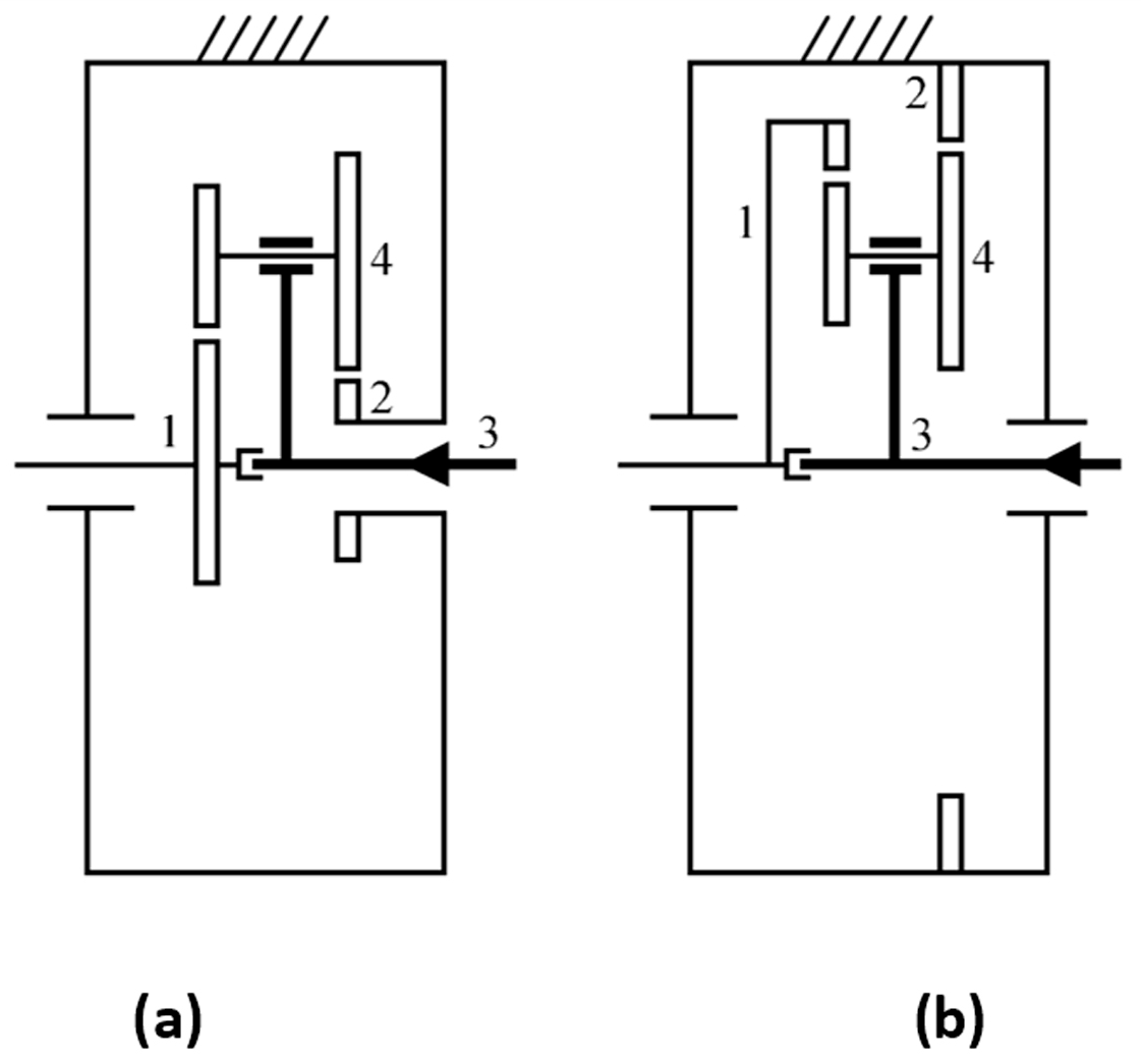
Figure 6Construction solutions for four-member planetary gear trains. (a) External gears. (b) Internal gears.
The two construction solutions for a 4-member self-locking PGT only allow power flow with input through the arm (Member 3) and output through the sun (Member 1), as shown in Fig. 6, where the power flow is in the direction marked by the arrow. The transmission ratio of the four-member PGT with input through the arm is (Salgado and Castillo, 2007):
For the design of the wheelchair locking system based on PGTs, we have considered the constraints on this type of transmission. These constraints can be grouped into two categories – one involving gear size and geometry, and the other the PGT meshing requirements, as will be detailed in the following two subsections.
4.1 Constraints involving gear size and geometry
The first constraint is a practical limitation of the range for the acceptable face width b. This constraint is as follows:
Where m is the module of the gears. All of the kinematic and dynamic parameters of the transmission depend on the values of the tooth ratios Zij. In theory, the tooth ratios can take any value, but in practice, they are limited mainly for technical reasons because of the difficulty in assembling gears outside of a certain range of tooth ratios. In this work, the tooth ratio for the design of mechanical spindle speeders are quite close to the recommendations of Müller (1982) and the American Gear Manufacturers Association (AGMA) norm (American Gear Manufacturers Association, 1988), and are:
with the constraint given by Eq. (7) being for external gears and that by Eq. (8) for internal gears. It is important to note that these constraints are valid for designs with different numbers of planets (Np) (Müller, 1982).
Another constraint that will be imposed on the design of 4-PGT with double planets, as the self-locking PGT implemented in the locking system design, is that the ratio of the diameters of the gears constituting a double planet is:
where d4 and are the pitch diameters of the gears than constitutes the planet gear that meshes with members 1 and 2 (see Fig. 6).
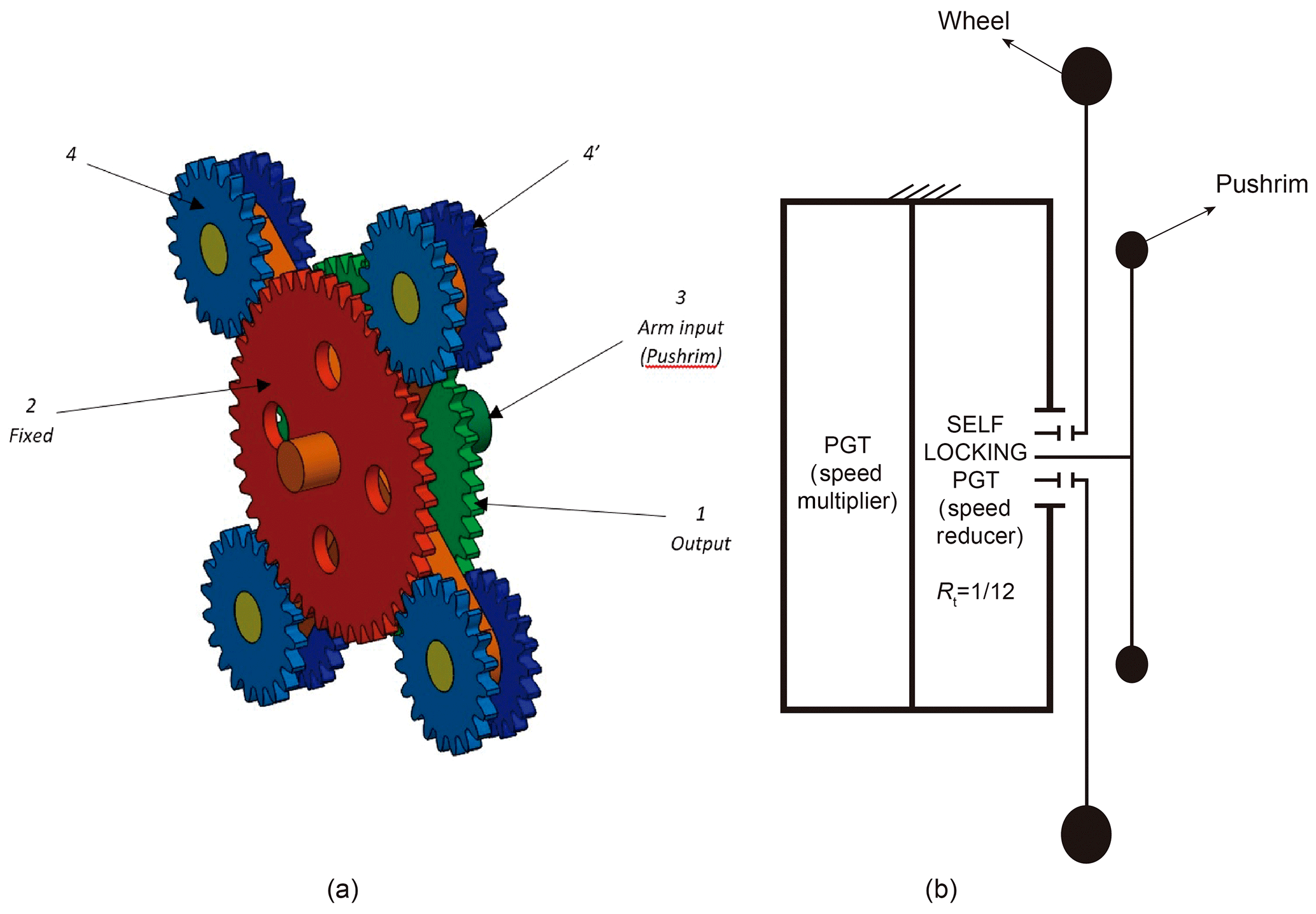
Figure 7(a) Design of the self-locking Planetary Gear Train with . (b) Scheme of the complete propulsion system.
4.2 Planetary gear train meshing requirements
The meshing requirements are given by the AGMA norm (American Gear Manufacturers Association, 1988). For planetary systems with double planets must, either of which, factorise with the number of planets in the sense of Eq. (10) below (see AGMA norm; American Gear Manufacturers Association, 1988):
where P1 and P2 are the numerator and denominator of the irreducible fraction equivalent to the fraction ; where is the number of teeth of the planet gear that meshes with member 1 and Z4 is the number of teeth of the planet gear that meshes with member 2 (see Fig. 6):
It can be verified that to satisfy the above requirements, and given that the 4-member PGT with arm input is a reduction transmission, the maximum transmission ratio (minimum reduction) that can be achieved so that a self-locking train is obtained, i.e., so that the constraints of Eqs. (4)–(11) are satisfied, is the one that has . Of the possible transmission ratios for a self-locking PGT, we chose this maximum.
As a specific design proposal to achieve , we propose the following teeth numbers for the self-locking PGT: Z1=48, Z2=44, Z4=20 and .
As mentioned above, and as can be checked in Fig. 4, the logical Rt values go from 5∕12 to 1∕12. Therefore, only in one case is the propulsion system a self-locking PGT. For the rest of the PI and slope values, a self-locking PGT + multiplier combination is necessary. In this work, we propose a PGT as multiplier stage since the speed is multiplied in a single step.
The self-locking PGT design with the planet member consisting of four gears (Np=4) is shown in Fig. 7a, and Fig. 7b is a schematic diagram of the complete propulsion system (self-locking PGT + multiplier PGT). The self-locking PGT is common to any design of the propulsion system. The member that varies depending on the needs of the user is the multiplier stage.
4.3 Force and stress analysis
As an example, we use an intermediate transmission ratio , which is the result of combining a self-locking PGT with and a multiplier PGT with Rt=5. The objective is to evaluate whether the propulsion system is small in size. To perform the calculations, two phases must be distinguished: when the system is locked, and when PI is input through the pushrim.
In the locking phase of the propulsion system, the value of Rt of the system is irrelevant since the stresses produced in the system depend solely on the slope and the chair-plus-user mass. For the calculations in this phase, one must decide on the value of the slope. We shall take a slope of 10 %. Since the system is locked, Fdrag=0 because it is not necessary to overcome any forces of friction. Thus, considering m=100 kg, the only force that the system supports is that of the weight, Fp:
The radius of the Wheel, rw is 270 mm. If no reduction system is used, the torque produced on the wheel's axis during this locking phase on a slope of 10 % will be:
This torque is distributed symmetrically through the two drive wheels. Hence, each locking system receives a torque of Nm. Each drive wheel is connected to the self-locking PGT's output gear (Gear 1) which will receive the full torque, and trigger the locking. Using the values given in Table 1 for the dimensions of the elements conforming the propulsion system, the tangential force produced by Nm on the cogs of Gear 1 will be N. Since they belong to the same member, planets 4′ and 4 distribute the torque produced by the locking symmetrically, and this will be that given by the tangential force exerted by the cogs of Gear 1. Figure 8 shows a method for calculating the resistance of the mechanism. This is the method used in Hwang et al. (2013), Li (2012), Moreira et al. (2016) and Patil et al. (2014) in which the resistance of the cog is calculated from the tangential force Ft(α>0) caused by the torque produced at the centre of the gear's pitch radius.

Figure 8(a) Stresses produced by the tangential forces applied to the cog during the blocking phase. (b) Areas in which the different contacts occur, and the application of the tangential force produced by the contact in the least favourable area.
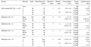
Table 1Size characteristics of the gears conforming the propulsion system, and the contact ratios between elements in contact and the dynamic loads on each element when is input through the pushrim.
When power is input through the push rim, the equations proposed in Del Castillo (2002) are used to calculate the torques and angular velocities of the components of the propulsion system (self-locking PGT + multiplier PGT) with power input to the self-locking PGT through the arm. These calculations were done using software developed in Matlab based on the aforementioned equations. Table 1 gives the size and dynamic characteristics of each member of the mechanism when a torque is input through the push rim. For the dynamics calculations, we considered the values of Rt represented in Fig. 4.
The increase in the torques produced in the self-locking PGT elements is due to the power recirculation that occurs in this type of self-locking PGT (Del Castillo, 2002). Thus, unlike in the locking phase of the system when the maximum torque supported by the self-locking PGT is limited by the size of the gears and the weight of the user, in this phase the limiting variable is the torque that is input onto the push rim where the greatest stresses arise.
As an example, we present a calculation of the stresses that arise on the cogs of the PGT's gears when a user is able to input a power of approximately 70 W, and wishes to climb a 7 % ramp. According to Fig. 4, the transmission ratio that is best suited to the needs of this case is . The speed of ascent, vslope=0.5 m s−1 is the consequence of inputting approximately Nm at ωl=4.44 rad s−1, which means that 9.5 Nm is applied to each push rim. As one observes in Table 1, taking into account the dimensions of the components of both the self-locking and the multiplier stages, the component which supports the greatest stress is Planet 4′ of the self-locking PGT. The results of the dynamic simulation with this force applied to the cog as in Fig. 8 are shown in Fig. 9.
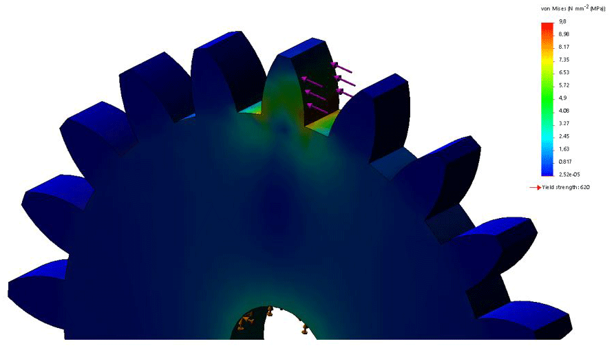
Figure 9Stresses produced by the tangential forces applied to the cog when the user inputs power through the push rim: the dynamic loads on Member 4′ (the least favourable).
Table 2Characteristics of the elements conforming the proposed propulsion system with .
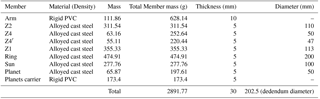
The cogs of Member 4′ can withstand the effects produced even in situations of steep slopes. This method has therefore allowed us to define the thicknesses and diameters of all the gears, and hence we can also define the approximate dimensions of the complete propulsion system.
With the stresses that arise in the elements of the propulsion system known, and its viability in terms of resistance confirmed, we can now approximate the overall dimensions of the system, as is illustrated in Fig. 10a for . An exploded view of the mechanism is included in Fig. 10b.
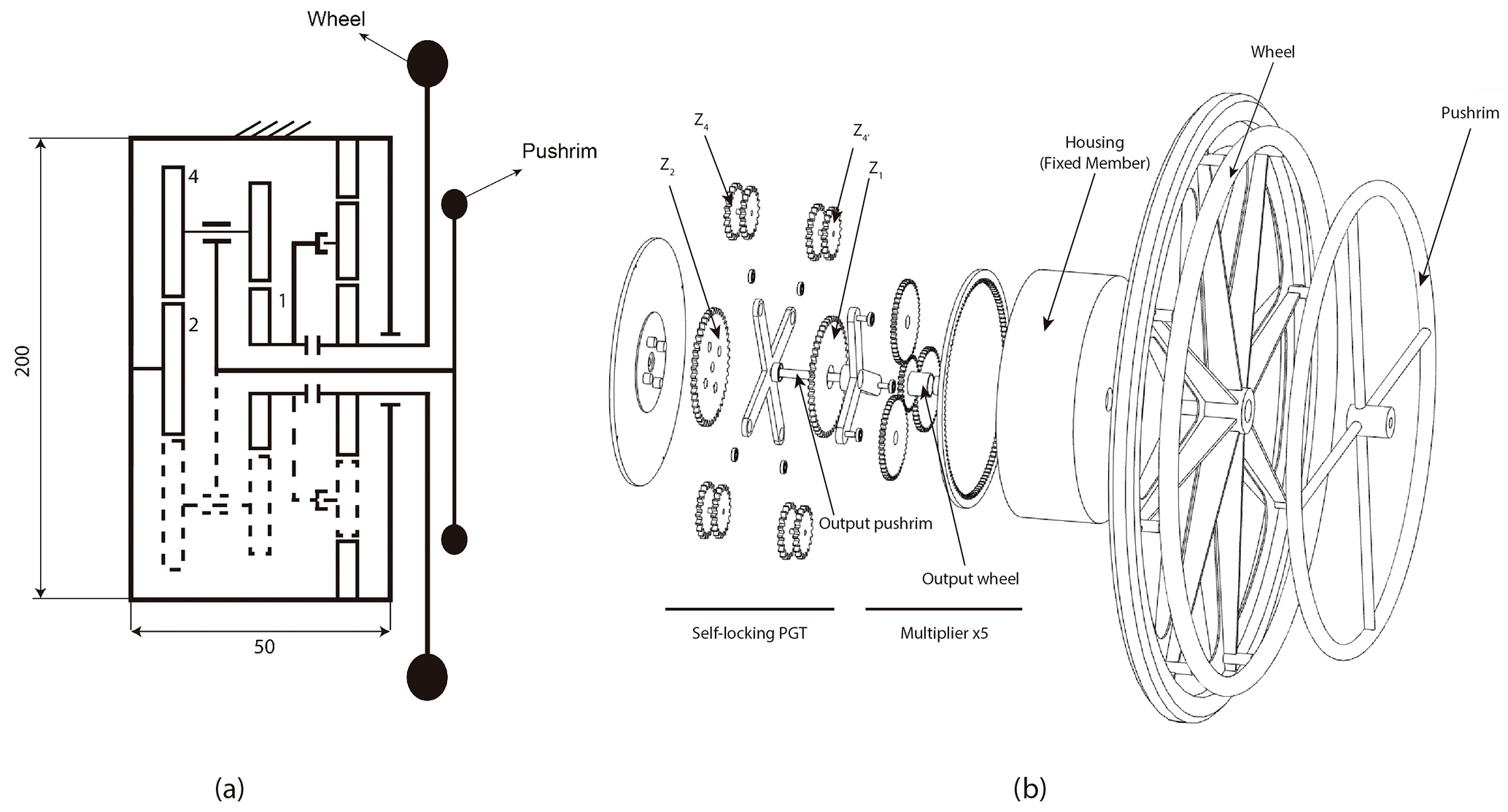
Figure 10(a) Diagram of the final transmission with the approximate values in mm of the width and height of the casing enclosing it, (b) Exploded view of the propulsion mechanism using a stage multiplier ×5.
Table 2 lists the specifications of each element of the transmission for . A relationship is established between the width and the height of the casing enclosing the transmission in order to have an approximation of the system's viability in terms of its dimensions.
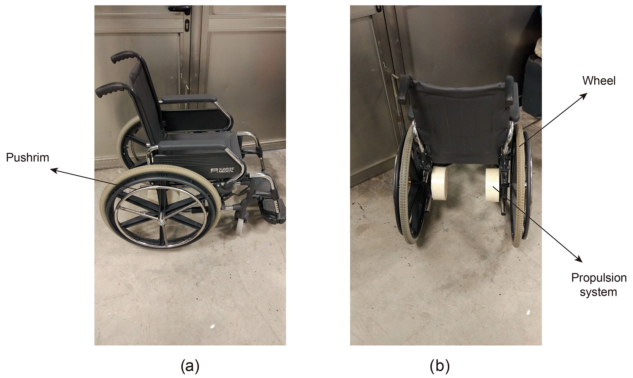

Figure 12(a, b) Different views of the propulsion system without power input (system self-locks) during both ascending (a) and descending trials (b). (c, d) Different views of the propulsion system with power input through the external rim (system moves) during both ascending (c) and descending trials (d).
In this work a prototype of the propulsion system has been tested in order to validate the reliability and the behaviour of the self-locking system in manual wheelchairs. The gears that formed the self-locking PGT and the multiplier stage were made of alloy steel. A ball bearing was used in gear 1 with 12 mm of diameter, the rest of the bearings of the prototype were needle bearings with 10 mm diameter each. The mounting of the prototype was as follows: gear 2 and the first part of the housing were joined together with screws which prevented gear 2 from moving. Planet gears 4 and 4′, the planet carrier and the input arm were mounted together. In this prototype a speed multiplier with a speed ratio of 5:1 was mounted at the output of gear 1. The sun element of the speed multiplier (output of the transmission) was connected to the wheel of the wheelchair. The second part of the housing encapsulated the transmission, thus forming an assembly which was subsequently joined to the chassis of the wheelchair using screws, leaving the housing as the fixed element of the transmission. An external pushrim was installed and connected to the input arm with the purpose of introducing power to the propulsion system. As mentioned in Fig. 1 there were two possible arrangements for the transmission, and the decision was taken to mount the prototype underneath the seat as can be seen in Fig. 11b which shows a rear view of the wheelchair. This configuration does not increase the width of the whole system. Once the prototype was mounted, the transmission had a .
The trials were conducted on a healthy subject with a height of 1.80 m and a mass of 80 kg. The ramp used for the trials was located at the main entry of a residential area, it had a 10 % slope and a length of 15 m. The first trial consisted of analysing the self-locking characteristic of the prototype. The subject was told to remain stationary and not to move the external pushrim. While the subject was on the slope in an uphill direction the power input was transferred from the wheel to the output of the self-locking PGT (gear 1), provoking the locking of the system and preventing the subject from rolling backwards. In the same way, when the subject was in a downhill direction, the prototype also self-locked. The subject was comfortable and did not feel any risk of rolling backwards or forwards while the prototype was locked. As can be seen in Fig. 12, panel (a) shows the user on an uphill ramp and panel (b) shows the user on a downhill ramp when the prototype is in the locking position. The first trial demonstrated that the system self-locked while the user was on a ramp without any power input.
The second trial consisted of introducing power through the external pushrim in order to test the motion of the prototype. By moving the external pushrim of the prototype, the power input was transferred from the input arm and thus moving gears 4 and 4′, provoking the motion of gear 1 (output of self-locking PGT) and consequently moving the wheelchair. The subject was told to move the pushrim at the speed he considered appropriate. While pushing the wheelchair through various cycles and then halting the motion, the subject felt comfortable throughout the trial and did not feel at risk of rolling backwards or forwards. Further, the user did not feel the effects of inertia when changing between a stationary position and motion. In Fig. 12 the user is introducing power to the system through the new external rim in both ascending (panel c) and descending (panel d) ramps. The ramp used was 10 % slope. Different repetitions ascending and descending the ramp were carried out.
It is evident that, on one hand, the system self-locks when the power is introduced through the wheel in both ascending and descending trials (Fig. 12, panels a and b). This behaviour prevents the user from going backwards ascending or going downhill while descending. On the other hand the system moves while the power is introduced through the external rim (Fig. 12, panels c and d).
In this work, we have described the design of a new propulsion system applied to manual wheelchairs for the ascent or descent of long ramps. The system consists of a self-locking planetary transmission and a push rim through which power is input to the mechanism. With this configuration, it is possible to design a system that makes it easier for the user to ascend long ramps and that self-locks when the user stops inputting power through the push rim. The chair therefore stops without any need for an external braking mechanism to be activated. Although the system is designed especially for climbing long ramps since this is the least favorable situation, it also allows the descent of ramps. In addition, it can be adapted to each user's physical conditions by selecting each transmission ratio according to that user's needs depending on the power that they can transmit.
It has to be emphasized that the system is made up of mechanical components and requires no external elements for its activation or deactivation. This allows the user to push the chair without fearing when it might be descending. Additionally, when they wish to resume motion, they will not need to overcome the force of inertia, but rather simply start pushing the chair again. All this makes the design characteristics of the propulsion system proposed in this work adaptable to any user.
Finally, the transmission was also built and tested on a manual wheelchair. In a qualitative way it has been demonstrated that the system self-locks while both ascending and descending a ramp when the power is introduced through the wheels. It has also been demonstrated that the propulsion system moves the wheelchair when the power is introduced through the external rim. For future works, lighter materials and considerations regarding the size of the device will be taken into account. The device will also be tested on impaired users with lower limb injuries and further studies like energy consumption and muscle behaviour will be analysed.
All the data used in this article can be obtained upon request from the corresponding author.
The authors declare that they have no conflict of
interest.
Edited by: Chin-Hsing
Kuo
Reviewed by: two anonymous referees
American Gear Manufacturers Association: American National standard?: design manual for enclosed epicyclic metric module gear drivers, American Gear Manufacturers Association, USA, 1988.
Anderson, N. E. and Loewenthal, S. H.: Spur-gear-system efficiency at part and full load, NASA Tech. Rep., 79–46, 1980.
Arnet, U., Van Drongelen, S., Veeger, D. J., and Van Der Woude, L. H. V.: Force application during handcycling and handrim wheelchair propulsion: An initial comparison, J. Appl. Biomech., 29, 687–695, https://doi.org/10.1123/jab.29.6.687, 2013.
Boninger, M. L., Cooper, R. A., Robertson, R. N., and Shimada, S. D.: Three-dimensional pushrim forces during two speeds of wheelchair propulsion, Am. J. Phys. Med. Rehab., 76, 420–426, 1997.
Boninger, M. L., Souza, A. L., Cooper, R. A., Fitzgerald, S. G., Koontz, A. M., and Fay, B. T.: Propulsion patterns and pushrim biomechanics in manual wheelchair propulsion, Arch. Phys. Med. Rehab., 83, 718–723, https://doi.org/10.1053/apmr.2002.32455, 2002.
Choi, Y. O., Lee, H. Y., Lee, M. H., and Kwon, O. H.: Effects of ramp slope on physiological characteristic and performance time of healthy adults propelling and pushing wheelchairs, J. Phys. Ther. Sci., 27, 7–9, https://doi.org/10.1589/jpts.27.7, 2015.
Chow, J. W., Millikan, T. A., Carlton, L. G., Chae, W. S., Lim, Y. T., and Morse, M. I.: Kinematic and Electromyographic Analysis of Wheelchair Propulsion on Ramps of Different Slopes for Young Men With Paraplegia, Arch. Phys. Med. Rehab., 90, 271–278, https://doi.org/10.1016/j.apmr.2008.07.019, 2009.
Dallmeijer, A. J., Kappe, Y. J., Veeger, D. H. E. J., Janssen, T. W. J., and van der Woude, L. H. V.: Anaerobic power output and propulsion technique in spinal cord injured subjects during wheelchair ergometry, J. Rehabil. Res. Dev., 31, 120–128, 1994.
De Groot, S., Veeger, H. E. J., Hollander, A. P., and Van der Woude, L. H. V.: Consequence of feedback-based learning of an effective hand rim wheelchair force production on mechanical efficiency, Clin. Biomech., 17, 219–226, https://doi.org/10.1016/S0268-0033(02)00005-0, 2002.
de Groot, S., Zuidgeest, M., and van der Woude, L. H. V.: Standardization of measuring power output during wheelchair propulsion on a treadmill. Pitfalls in a multi-center study, Med. Eng. Phys., 28, 604–612, https://doi.org/10.1016/j.medengphy.2005.09.004, 2006.
Del Castillo, J. M.: The analytical expression of the efficiency of planetary gear trains, Mech. Mach. Theory, 37, 197–214, https://doi.org/10.1016/S0094-114X(01)00077-5, 2002.
Diab, Y., Ville, F., and Velex, P.: Prediction of Power Losses Due to Tooth Friction in Gears, Tribol. T., 49, 266–276, https://doi.org/10.1080/05698190600614874, 2006.
Flemmer, C. L. and Flemmer, R. C.: A review of manual wheelchairs Claire, Disabil. Rehabil. Assist. Technol., 11, 177–187, https://doi.org/10.3109/17483107.2015.1099747, 2016.
Howarth, S. J., Pronovost, L. M., Polgar, J. M., Dickerson, C. R., and Callaghan, J. P.: Use of a geared wheelchair wheel to reduce propulsive muscular demand during ramp ascent: Analysis of muscle activation and kinematics, Clin. Biomech., 25, 21–28, https://doi.org/10.1016/j.clinbiomech.2009.10.004, 2010.
Hwang, S. C., Lee, J. H., Lee, D. H., Han, S. H., and Lee, K. H.: Contact stress analysis for a pair of mating gears, Math. Comput. Model., 57, 40–49, https://doi.org/10.1016/j.mcm.2011.06.055, 2013.
Koontz, A. M., Cooper, R. A., Boninger, M. L., Yang, Y., Impink, B. G., and van der Woude, L. H. V.: A kinetic analysis of manual wheelchair propulsion during start-up on select indoor and outdoor surfaces, J. Rehabil. Res. Dev., 42, 447, https://doi.org/10.1682/JRRD.2004.08.0106, 2005.
Kwarciak, A. M., Yarossi, M., Ramanujam, A., Dyson-Hudson, T. A., and Sisto, S. A.: Evaluation of wheelchair tire rolling resistance using dynamometer-based coast-down tests, J. Rehabil. Res. Dev., 46, 931–938, https://doi.org/10.1682/JRRD.2008.10.0137, 2009.
Li, S.: Contact Stress and Root Stress Analyses of Thin-Rimmed Spur Gears With Inclined Webs, J. Mech. Design, 134, 51001, https://doi.org/10.1115/1.4006324, 2012.
Lin, C.-J., Lin, P.-C., Su, F.-C., and An, K.-N.: Biomechanics of wheelchair propulsion, J. Mech. Med. Biol., 9, 229–242, https://doi.org/10.1142/S0219519409002948, 2009.
Meginniss, S. M. and SanFrancisco, A. S.: Two-Speed manual wheelchair wheel, United States Pat. Appl. Publ., 53, US 2006/0197302 A1, 2006.
Moreira, P., Ramôa, P., and Flores, P.: Design of a new knee orthosis locking system, Proceedings of the ASME 2013 International Mechanical Engineering Congress and Exposition IMECE2013, 15–21 November 2013, San Diego, California, USA, https://doi.org/10.1115/IMECE2013-64276, 2016.
Müller, H.: Epicyclic drive trains: Analysis, synthesis, and applications, Wayne University Press, Detroit, USA, 1982.
Patil, S., Karuppanan, S., Atanasovska, I., and Wahab, A. A.: Frictional Tooth Contact Analysis along Line of Action of a Spur Gear Using Finite Element Method, Proc. Mat. Sci., 5, 1801–1809, https://doi.org/10.1016/j.mspro.2014.07.399, 2014.
Richter, W. M., Rodriguez, R., Woods, K. R., and Axelson, P. W.: Stroke Pattern and Handrim Biomechanics for Level and Uphill Wheelchair Propulsion at Self-Selected Speeds, Arch. Phys. Med. Rehab., 88, 81–87, https://doi.org/10.1016/j.apmr.2006.09.017, 2007.
Robertson, R. N., Boninger, M. L., Cooper, R. A., and Shimada, S. D.: Pushrim forces and joint kinetics during wheelchair propulsion, Arch. Phys. Med. Rehab., 77, 856–864, https://doi.org/10.1016/S0003-9993(96)90270-1, 1996.
Salgado, D. R. and Castillo, J. M.: Conditions for self-locking in planetary gear trains, J. Mech. Des.-T. ASME, 129, 960–968, https://doi.org/10.1115/1.2748449, 2007.
Sonenblum, S. E., Sprigle, S., and Lopez, R. A.: Manual Wheelchair Use: Bouts of Mobility in Everyday Life, Rehabil. Res. Pract., 2012, 1–7, https://doi.org/10.1155/2012/753165, 2012.
Sprigle, S. and Huang, M.: Impact of Mass and Weight Distribution on Manual Wheelchair Propulsion Torque, Assist. Technol., 27, 226–235, https://doi.org/10.1080/10400435.2015.1039149, 2015.
van der Woude, L., Dallmeijer, A., Janssen, T., and Dirjkan, V.: Alternative Modes of Manual Wheelchair Ambulation, Am. J. Phys. Med. Rehab., 80, 765–777, doi:10.0894-9115/01/8010-0765/0, 2001.
van der Woude, L. H., Hendrich, K. M., Veeger, H. E. J., van Ingen Schenau, G. J., Rozendal, R. H., de Groot, G., and Hollander, A. P.: Manual wheelchair propulsion: effects of power output on physiology and technique, Med. Sci. Sport. Exer., 20, 70–78, https://doi.org/10.1249/00005768-198802000-00011, 1988.
Van Der Woude, L. H. V., Geurts, C., Winkelman, H., and Veeger, H. E. J.: Measurement of wheelchair rolling resistance with a handle bar push technique, J. Med. Eng. Technol., 27, 249–258, https://doi.org/10.1080/0309190031000096630, 2003.
van der Woude, L. H. V., de Groot, S., and Janssen, T. W. J.: Manual wheelchairs: Research and innovation in rehabilitation, sports, daily life and health, Med. Eng. Phys., 28, 905–915, https://doi.org/10.1016/j.medengphy.2005.12.001, 2006.
Vanlandewijck, Y., Theisen, D., and Daly, D.: Wheelchair propulsion biomechanics: implications for wheelchair sports, Sport. Med., 31, 339–367, https://doi.org/10.2165/00007256-200131050-00005, 2001.
Veeger, H. E. J., Van Der Woude, L. H. V., and Rozendal, R. H.: Load on the Upper Extremity in Manual Wheelchair Propulsion, J. Electromyogr. Kines., I, 270–280, https://doi.org/10.1016/1050-6411(91)90014-V, 1991.
Xu, H. and Kahraman, A.: A Frictional Efficiency Loss Model for Helical Gears, ASME 2005 Int. Des. Eng. Tech. Conf. Comput. Inf. Eng. Conf., 1–12, https://doi.org/10.1115/DETC2005-85243, 2005.