the Creative Commons Attribution 4.0 License.
the Creative Commons Attribution 4.0 License.
 | 28 Sep 2018
The nonlinear vibrations of orthogonal mechanism of vibrating table in view of friction
Zharilkassin Iskakov
Kuatbay Bissembayev
Nutpulla Jamalov
In dynamics of the orthogonal mechanism of vibrating table main attention is paid to the effect of friction on vibrational process when it is interacting with non-ideal energy source. As a result of analysis of numerical solutions of nonlinear equation of motion, it is established that in general, for the period of rotation, both sliding friction and rotational friction increase the difference between the maximum and minimum angular velocity values of the driving link (engine shaft) when its average value is constant; both increase the coefficient of non-uniformity of rotation. When there is a cargo of significant mass in the working link, the effect of sliding friction impacts more on the amplitude and frequency of the angular velocity oscillations of the driving link (engine shaft) and on the frequency of the coordinate changes, as well as on the frequencies and maximum and minimum values of the projections of the velocity and acceleration of the hinge linking the work platform to coupler. Similarly, the larger of the load mass, the stronger the effect of rotational friction on the amplitude and frequency of angular velocity oscillations of the driving link (engine shaft).
- Article
(3015 KB) - Full-text XML
- BibTeX
- EndNote


In recent years the vibration equipment in the mechanical engineering practice is developed based on the lever mechanisms. These mechanisms have a unique opportunity to create a vibratory motion of the working member. Development of vibration mechanisms on the basis of mathematical modelling gives the results acceptable for the practice. The structural scheme of vibrating machines usually are not complicated, but for the successful operation it is necessary to determine accurately their parameters that can only be done on the basis of studies of the dynamics of vibrating machines and processes performed by them.
The fundamental and applied research works on the vibration machines mechanics, mechanisms and technologies performed under the guidance of K. V. Frolov (Frolov, 1982, 1988; Frolov and Goncharevich, 1985) can be fitted into the towering achievements in the field of theory of mechanisms and machines. The method of applying of nonlinear mechanics asymptotic techniques and Markov processes theory for study of random vibrations in the viscoelastic systems exposed to random forces has been developed in them. The theory of impact of the vibration on the nonlinear mechanical system has been constructed. The theory of vibratory displacement, theory of oscillating systems with limited excitation, theory of structural damping and some other studies of systems with distributed dry friction, theory of vibroconductivity, vibrorheology, theory of impact of vibration on pulps and suspensions were developed substantially.
The scientists from Chemnitz University of Technology (Germany) engage on development of vibration machines using the nonlinear properties of linkage mechanisms to obtain the oriented impulse at the need amplitude (Dresig et al., 1994; Dresig and Golle, 2001). They have developed the “Erreger” program for dynamic designing of cyclic impulse mechanisms.
For creation of vibration machines based on lever mechanisms, Kyrgyz scientists use “special” position of four link mechanisms. Works by Abdraymov et al. (2015) and Abdraymova (2009) consider characteristics of variable structure mechanisms by S. Abdraimov for creation of impact machines, used in road-construction, mining and other branches of industry.
Any real engine has original limitations, determined by the characteristics of its power. If the power consumed by the oscillating system is comparable in magnitude, with the power of the energy source, then the source of energy of such limited power is named “non-ideal source”. Such the energy source not only affects the oscillatory system and at the same time experiences a response from the vibrational system. Changing the parameters of the system's oscillations can be accompanied by a change in the mode of operation of the energy source. Accordingly, such an oscillatory system is named “non-ideal system” (Kononenko, 1980). In case of limitation of the power of the energy source, in result of strong interaction between dynamic system and engine, Somerfield effect, requiring the increase in power from the energy source (Kononenko, 1980; Alifov and Frolov, 1985), is manifested, a linear two mass system has regular vibration motion within 1:1 resonance passing, and the maximum amplitude increases only during passing the resonance (Tsuchida et al., 2003). Vibration in a linear with two degrees of freedom mass system with a drive and non-ideal source and nonlinear rotation moment, is regular before resonance, and irregular during and after 1:1 resonance passing (Tsuchida et al., 2003). In a non-ideal system with two degrees of freedom, consisting of a dumped nonlinear oscillator, connected with rotation part, manifestation of Hopf bifurcation is a common property of non-ideal problems, related to hopping phenomenon (Dantas and Balthazar, 2003, 2004). Self-synchronization of shafts (a well-known nonlinear phenomenon), in result of which two or more unbalanced shafts fixed on a common moveable structure, may rotate synchronically, only due to interaction through structural vibrations, even in case of lack of any direct kinematic link (Dimentberg et al., 1997). In a motor-frame system of direct current with slow growth of power levels, Somerfield effect occurs in resonance, due to the lack of power for attaining higher velocity regimes with low energy consumption (Felix et al., 2005). Saturation of a high frequency and low amplitude regime and the transfer of energy to the regime of high amplitude with low frequency are possible, if non-ideal system frequency is equal to double own frequency of the frame, i.e. 2:1 of internal resonance (Tsuchida et al., 2005). In non-ideal and nonlinear mechanical systems, irregular motion is evident, the control of chaos may be oriented to oscillator (Zukovic and Cveticanin, 2009), and not to the engine, controlling the voltage of the direct current engine, as it is usually done. Complete review of different models and methods of dynamic analysis of non-ideal vibrating systems is provided and discussed in works (Balthazar et al., 2002, 2003; Cvetićanin, 2010). It should be marked that back action of a vibrating system on the source of excitation changes the rotation velocity of engine shaft. In previous works, it was not paid serious attention, being considered that variation of angular velocity of engine shaft is insufficient. In fact, in some cases, for example, in case of low-velocity rotations of engine shaft, the amplitude of vibrations of angular velocity is rather significant, which should be taken into account in dynamic analysis of vibrating system. Characteristics of variation of angular velocity of engine shaft depends not only on parameters of energy source, but also on parameters of the system itself.
One type of the vibrating equipment is vibrating table with flat lever mechanism has a broad prospect of using in the construction industry, in the chemical, pharmaceutical and food industries and in the mining industry.
In the work of Bisembayev and Iskakov (2012), dynamical and mathematical models of the orthogonal mechanism of a vibrating table with non-ideal energy source have been created. The rotational and librational motions (Gulyaev et al., 1989; Goldstein, 1975) of the mechanism have been examined (Bissembayev and Iskakov, 2015a). With stable rotational operating conditions of the mechanism, it was shown that the value of the angular velocity of the driving link varies about its average value. The frequency of the change in the value of the angular velocity equals the average value of this velocity, and the amplitude is inversely proportional to this value. The average value of the angular velocity depends on the length of the driving link and the characteristics of the energy source. The conditions imposed on the amplitude of driving link's vibrations were defined. The law of variation of the amplitude of the librational motion of a given link and the dependence of the frequency of oscillatory motion on the amplitude, on the parameters of the energy source and mechanism are established. Criteria of stability of the rotational and librational motions of orthogonal mechanism have been found. The dynamics of orthogonal mechanism in the presence of a shaking table of fixed load is studied in the work of Bissembayev and Iskakov (2014). The focus is on the vibrational motion of the mechanism in slow-velocity engine rotation. The character of changing amplitude the angular velocity of the driving link, depending on the mass of the load and the length of the driving link, is determined. Dependence of the mean angular velocity on the motor torque is set. In the report of Bissembayev and Iskakov (2015b) as a non-ideal energy source a damless hydraulic turbine with inclined blades was used. It is established that the angular velocity of a hydraulic turbine depends on the values of its parameters and the parameters of the system affect the amplitude of the angular velocity. The dependence of the coefficient of non-uniformity of rotation on the parameters of the system was found.
In the papers of Bissembayev and Iskakov (2014, 2015a, b), the dynamic analysis of the vibrational system is performed without taking into account the friction in kinematic pairs. If we take into account that in the orthogonal mechanism under consideration there is a certain friction in the kinematic pairs and with a change in the parameters of the system, for example, as the load mass in the working link increases, the effect of friction on the dynamics of the system becomes more significant, then, for more accurate dynamic analysis, its influence is undoubtedly necessary to take into account.
The purpose of this paper is to study the effect of friction in kinematic pairs on the dynamics of the orthogonal mechanism of a vibrating table with a low-velocity engine when there is a constant motionless load in the working link.
Structural scheme of orthogonal mechanism is shown in the Fig. 1. We place the origin of the coordinate system in the axis of rotation of the crank. Here, X and Y denote the coordinates of the hinge joint C connecting the work table 4 to coupler 3 (Fig. 1). From the closedness equation of vector contours in projections to the coordinate axes the following kinematic relations (Bissembayev and Iskakov, 2014, 2015a; Tuleshov, 2010) can be written
where l, l1, l2 are length of links 1–3, respectively, φ – the crank rotation axis angle (Fig. 1).
Expressions of maximum, minimum and average values of the coordinates X and Y are given in articles of Bissembayev and Iskakov (2014, 2015a).
As the calculations (Bissembayev and Iskakov, 2014, 2015a) show, the amplitude of the horizontal and vertical vibrations of hinge C of orthogonal mechanism with respect to the mean values of the coordinates are equal to each other and equal to the length of the crank l.
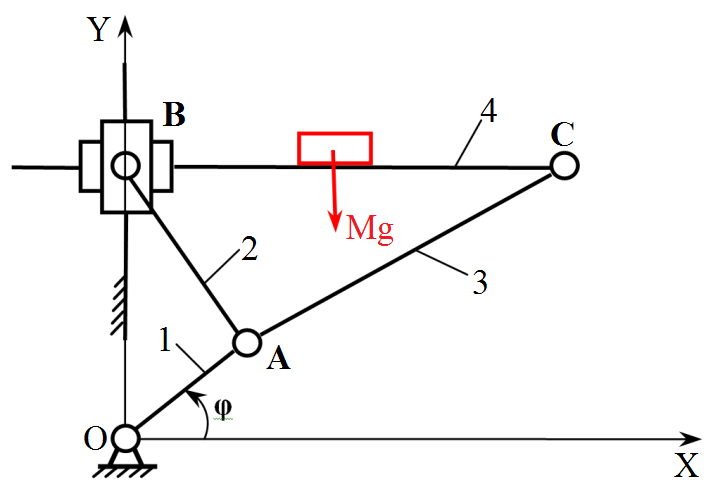
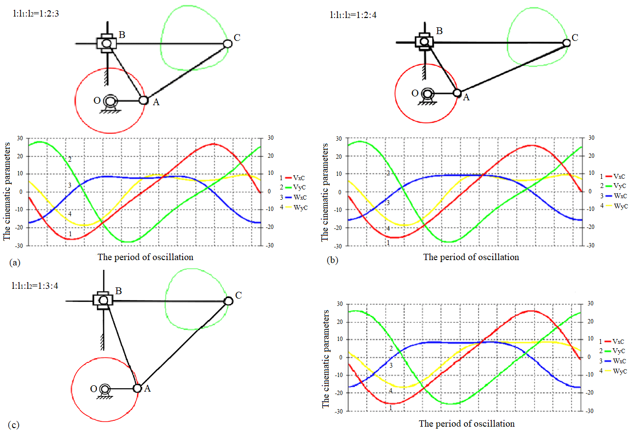
Figure 2Structural model of the orthogonal mechanism and the graphs of variance projection components of analogues of velocity and acceleration of the operating point C in the different ratios of the lengths of links .
Projections of the velocity of hinge C relative to the coordinate system OXY are equal to its projections in coordinate system O′ξη, beginning of which is located in the average values of coordinates X and Y
Also projections of acceleration of point C of working link in the coordinate system OXY are equal to its projections in the coordinate system O′ξη
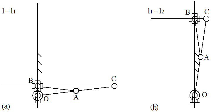
Structural model of the orthogonal mechanism of vibrating table in the different ratios of the lengths of links and, respectively, the graphs of variance projection components of analogs of velocity and acceleration of pin joint C performed by specialized software package (Jamalov and Kamal, 2015), are shown in Fig. 2, and motion paths of knee joints, including pin joint C are also shown here. The motion begins from the right horizontal position of the crank. From here, it is easy to observe that the change in the ratio of the lengths of links not only affects the values of velocity and acceleration, but also their graphical behaviour. Laws of velocity and acceleration change are nonlinear at lengths of the links. Changes in the behaviours of the graphs vy, wx and wy are clearly visible when length l1 or when l2 is changing at the same length of crank. The developers of orthogonal mechanism of vibratory table can select the appropriate option of size and ratio of the lengths of links depending on the process requirements. Thereby, they should take into account that the condition cannot be implemented, because when l=l1 the pin joints O and B will merge and mechanism will falls into a special position (Fig. 3a), i.e. ceases to be crank-type and work. When l1=l2 – it degenerates, i.e. hinge joints B and C will merge (Fig. 3b), hence the links 2 and 3 will merge, therefore, the condition should be achieved.
Let us generate a differential equation of the motion of orthogonal mechanism of vibrating table. We choose as the generalized coordinate of the parameter φ (Figs. 1 and 4).

Figure 4Diagram of the mechanism of vibrating table indicating the forces exerted on kinematic pairs.
From Fig. 4, can make sure the validity of the following kinematic relations
To derive the equation of the motion of orthogonal mechanism of vibrating table we use Lagrange equation of the second kind (Matveev and Matveeva, 2009).
Kinetic energy of the system is given by:
where X, Y, φ, φ1, φ2 are system coordinates (Fig. 4), m2 is link mass 3 and M is load mass subject to link mass 4 and J, J1 and J2 is a moment of inertia of links 1–3 correspondingly.
Potential energy of the system shall be represented as follows
Placing the relations (Eqs. 6 and 7) in Eq. (8) and after some transformations, we will have the expression of kinetic energy as follows
Potential energy of the system is given by
Friction forces occur in kinematic pairs of mechanism of vibrating tables, in many cases, these forces significantly influence on the motion of mechanism. In determination of the friction force, we will rely on the friction law, which is referred to as Amonton-Coulomb (Leonov and Leonov, 2008; Timofeev, 2010; Borisenko, 2011; Tarabarin et al., 2012).
In accordance with this law, modules of friction forces and their moments shall be accepted as proportional to modules of normal reactions. There are two prismatic and four revolute pairs in an orthogonal mechanism of vibrating table (Fig. 4).
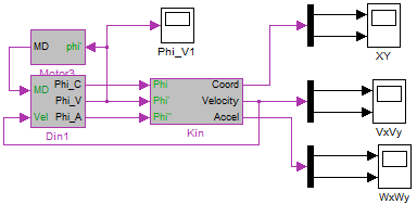
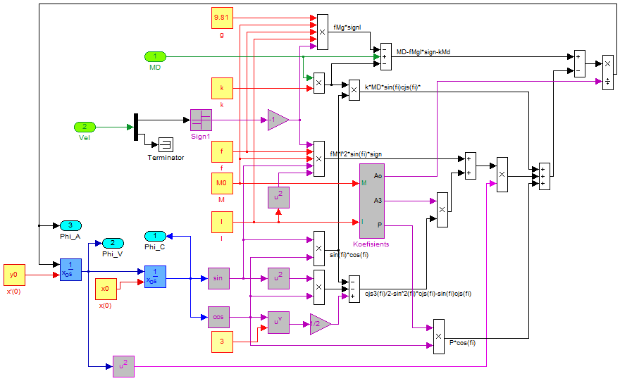
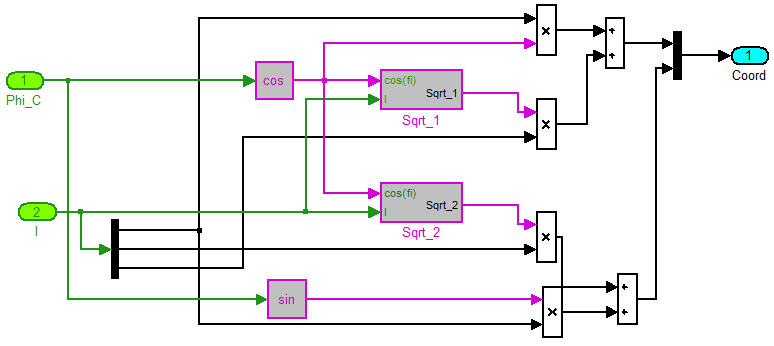

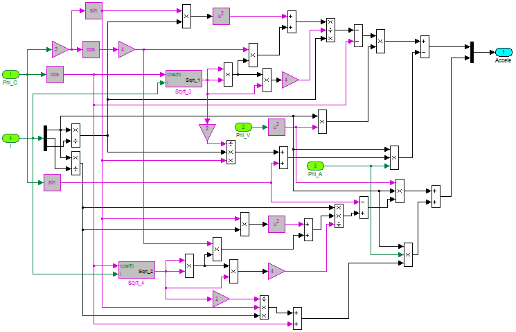
Figure 9Determination of projection of point C acceleration (calculation using Eqs. 4 and 5).
We determine the friction in the guides of the prismatic pair, and we assume that, due to a sufficient gap in this pair, the link 4, when it is skewed, touches the guides at two points spaced a distance c (Fig. 4). The reaction forces at the points of contact are equal to Na and Nb. Consequently, the sliding friction forces arising in the guides of the prismatic pair, due to the skew of the link 4, have the form
The frictional forces that occur when the guides move in the vertical direction take on the form
The frictional forces arising in the prismatic pair along the x-axis can be determined from
where
The frictional forces in the prismatic pair along the y-axis are:
where f is the coefficient of sliding friction.
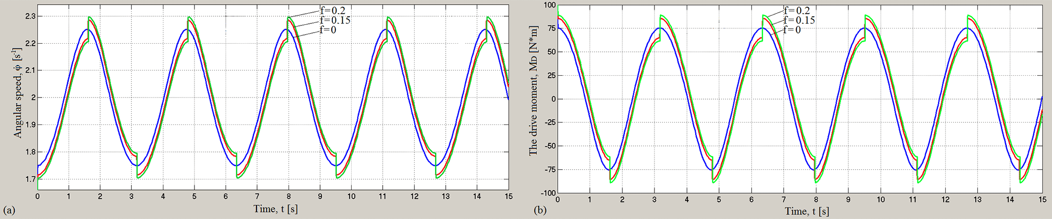
Figure 10Dependencies of angular velocity (a) and engine torque (b) on the time at different values of the coefficient of sliding friction f and for value of coefficient of rotational friction k=0.
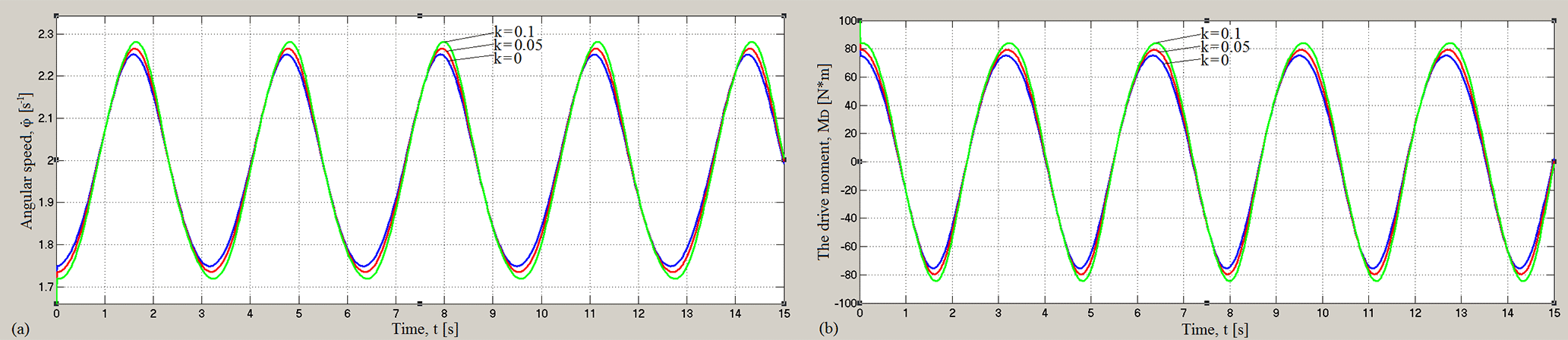
Figure 11Dependencies of angular velocity (a) and engine torque (b) on the time at different values of the coefficient of rotational friction k and for value of the coefficient of sliding friction f=0.
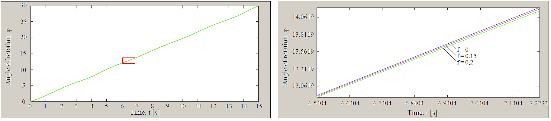
Figure 12Dependence of rotation angle of the driving link (engine shaft) on time at different values of the coefficient of sliding friction f and for value of coefficient of rotational friction k=0.
Now, let us determine the friction forces, occurring in revolute pair
where
Here Ffr1, Ffr2 and Ffr3 – are the frictions in revolute kinematic pairs 5, 6 and 7 correspondingly, k1, k2, k3 are coefficients of friction of rotation in the 5, 6 and 7 hinges. Placing Eqs. (12) and (13) in Eq. (14) we have
Taking into account expressions (Eq. 6), let us rewrite to formulae for friction Eqs. (12)–(14) as follows
Generalized friction forces will be determined from the condition of equality of elementary work of these forces on possible displacements, coinciding with variations of generalized coordinates, to elementary works of frictional forces applied to the orthogonal mechanism
where r1, r2 and r3 are radii of the fifth, sixth and seventh hinge.
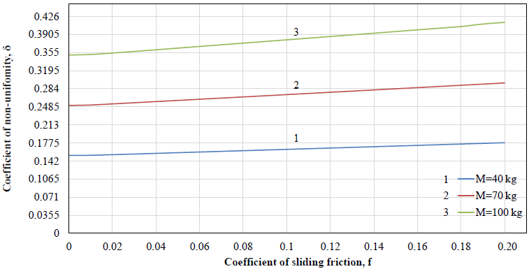
Figure 13Dependences of coefficient of non-uniformity of rotation δ from coefficient of sliding friction f at coefficient of rotational friction k=0 and for different values of load mass M.
From the geometry of the scheme of the orthogonal mechanism of the vibrating table, can make sure the validity of the following relation
Generalized slipping friction forces
Generalized frictional forces of rotation
where MD is a moment of driving forces of engine, to simplify the calculation, it is assumed that is the reduced coefficient of rotational friction, in what follows it will be called simply the coefficient of rotational friction.

Figure 14Dependences of coefficient of non-uniformity of rotation δ from coefficient of rotational friction k at coefficient of sliding friction f=0 and for different values of load mass M.
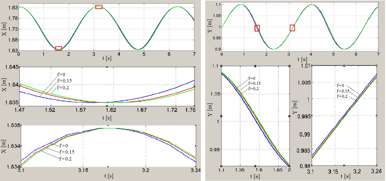
Figure 15Graphs of coordinates X(t) and Y(t) of point C for different values of the coefficient of sliding friction f and for coefficient of rotational friction k=0 and for load mass M=70 kg.
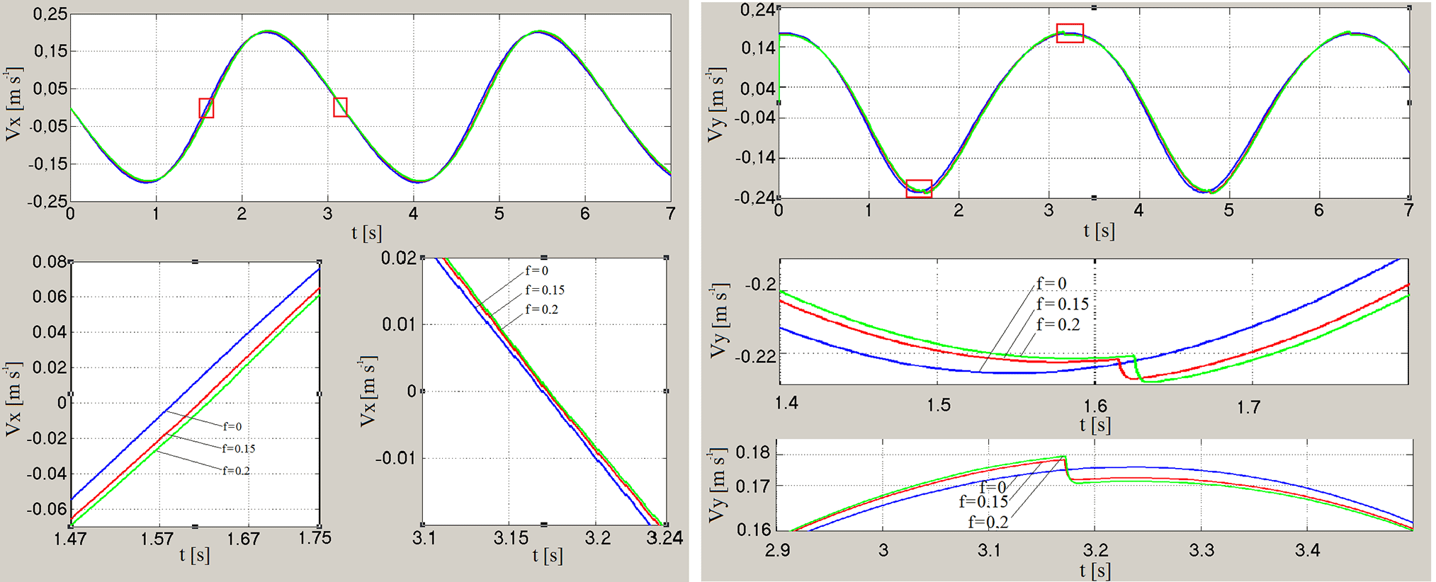
Figure 16Graphs of velocity projections Vx(t) and Vy(t) of point C for different values of the coefficient of sliding friction f and for coefficient of rotational friction k=0 and for load mass M=70 kg.
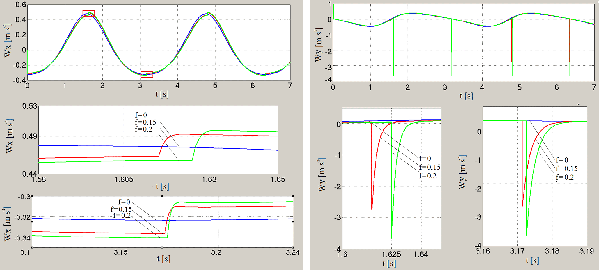
Figure 17Graphs of acceleration projections Wx(t) and Wy(t) of point C for different values of the coefficient of sliding friction f and for coefficient of rotational friction k=0 and load mass M=70 kg.
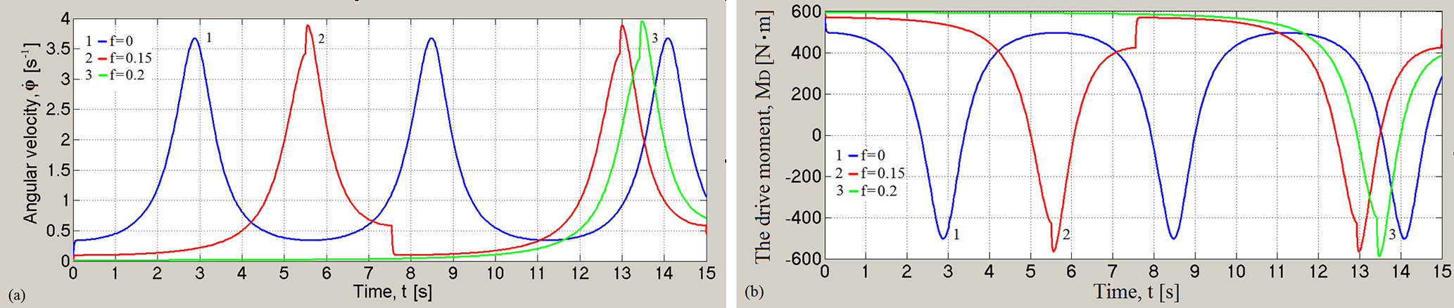
Figure 18Graphs of angular velocity of the rotation of driving link (engine shaft) (a) and engine torque MD (b) at different values of the coefficient of sliding friction f and for coefficient of rotational friction k=0 and for load mass M=500 kg.
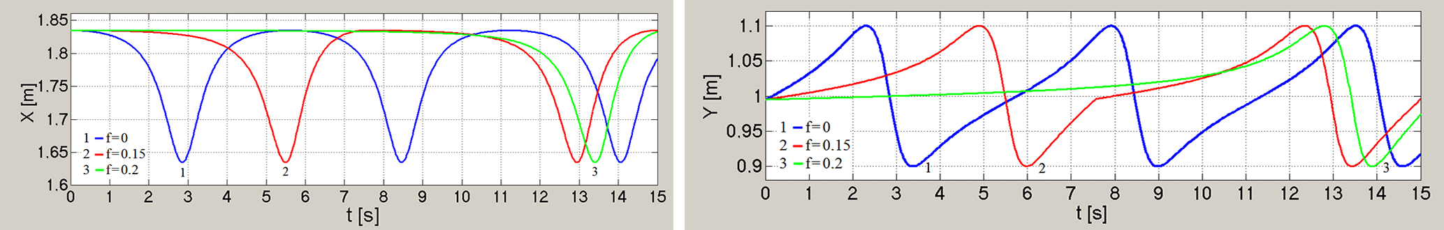
Figure 19Graphs of coordinates X(t) and Y(t) of point C at different values of the coefficient of sliding friction f and for coefficient of rotational friction k=0 and for load mass M=500 kg.

Figure 20Graphs of velocity projections Vx(t) and Vy(t) of point C at different values of the coefficient of sliding friction f are different and for coefficient of rotational friction k=0 and for load mass is M=500 kg.
In expressions (Eqs. 10, 11 and 21–25), there are second order terms of smallness, and subject to condition of , ignoring them, we will have
where
Let us write Lagrange equation of second kind
By placing Eqs. (26)–(32) in Eq. (34), we will have the equation of motion of orthogonal mechanism of vibrating table, represented by
After simplification, the equation of motion of orthogonal mechanism will be given by
Here
where M is load mass, m3 is mass links 4.
Influence of non-ideal energy source on the vibratory system has to be expressed in the form of the MD(φ, ), where φ – coordinate the motion of energy source. Torque on the shaft of some engine, for example, of the DC engine is determined by the equation
where a and b – constant coefficients, depending on the engine parameters.
From the equation of motion of orthogonal mechanism (Eq. 36) on the basis of Eq. (38) we find the condition for its static equilibrium
Here the Eq. (39) is taken with the minus sign in the interval and with the plus sign in the interval .
Condition (Eq. 39) at is determined by the equation
Hence we find the excitation condition of rotatory (rotary) motion at in the form of
Simulink model of work of the vibration table was developed to conduct numeric calculations, general view of which presented in Fig. 5. Here the nonlinear differential Eq. (36) on the basis of Eq. (38) was solved using the flowchart shown in Fig. 6. Calculation of coordinates of the point C (1), as well as projections of its velocity (2, 3) and projections of acceleration (4, 5) were conducted using the flowchart shown in Figs. 7–9. The input signals for the model are the mass of the load, the mass of the links, the friction coefficients, as well as the initial position and the initial angular velocity of the driving link.
Calculations were performed for the following values of parameters: , , M=70 kg, m=2 kg, kg, m2=3 kg, m, l1=1 m, l2=2 m.
The results of the solution of Eq. (36) in the absence of friction are completely consistent with the results of paper of Bissembayev and Iskakov (2014).
The graphs of dependence of the angular velocity of the driving link (engine shaft) and dependence of engine torque MD on the time t at different values of the coefficient of sliding friction f and for various values of coefficient of rotational friction k are shown in Figs. 10 and 11. The graphs in the Fig. 10a shows that the average angular velocity depends on the coefficient of sliding friction, and at that in the first half cycle of rotation of the mechanism under the influence of sliding friction this value decreases, but in the second half-cycle – increases due to reversal of sign the sliding friction. The amplitude of the angular velocity of the driving link depends on rotational friction; it increases with increasing of the rotational friction coefficient (Fig. 11a). Both types of friction affect the maximum and the minimum value of the angular velocity per rotation cycle, by increasing the difference between these values. In this case the average value of angular velocity remains constant.
Figures 10b and 11b show the engine torque waveforms with significant amplitude and influence of sliding and rotational friction on them.
Dependence of the rotation angle of the driving link φ on time t is represented in the Fig. 12, which shows the similar upward shift of the dependence diagram φ(t) along the whole line under the influence of the coefficient of sliding friction. Rotational friction coefficient due to the smallness of its value does not affect practically the behaviour of the dependence φ(t).
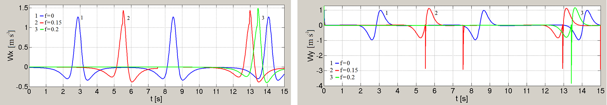
Figure 21Graphs of acceleration projections Wx(t)∦Wy(t) of point C at different values of the coefficient of sliding friction f and for coefficient of rotational friction k=0 and for load mass M=500 kg.
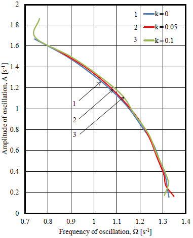
Figure 22Amplitude-frequency responses of oscillations of angular velocity of the driving link of a mechanism in different values of coefficient of rotational friction and coefficient of sliding friction f=0.
At steady state the velocity of the driving link even if remains constant at the average, but it changes within the cycle, passing through the maximum and minimum values. The rotation non-uniformity estimated by the coefficient of non-uniformity
where – average velocity per cycle. Ratio δ describes peak-to-peak value of velocity oscillations with respect to its mean value. The smaller δ, the relatively smaller peak-to-peak of the velocity oscillations, the calmer the driving link rotates. From this point of view, both sliding friction, and rotational friction increase the difference between maximum and minimum values of angular velocity while its average value per cycle of rotation stays constant (Figs. 10a and 11a), both increase the coefficient of non-uniformity of rotation (Figs. 13 and 14), taking a destabilizing effect.
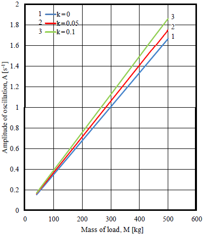
Figure 23Dependence of the amplitude of oscillations of angular velocity on the load mass in different values of coefficient of rotational friction and coefficient of sliding friction f=0.
Graphic dependences of coordinates, projections of velocity and acceleration of the point C at the load mass on working link M=70 kg, for different values of the coefficient of sliding friction and for coefficient of rotational friction k=0 are shown in the Figs. 15–17. Effect of friction on kinematical parameters of hinge C motion exerts in mixing of their graphs and jumps when the sign of friction force changes, especially it is well seen in time dependent graphs of point C acceleration projections (Fig. 17).
If driving torque is insufficient for a complete rotation of orthogonal mechanism, then vibration table performs librational oscillations.
A condition when librational oscillations of mechanism take place at
Therefore on the basis of Eq. (33) condition of librational oscillations for values of load mass M
Similar condition for driving link length values l
in this case it is necessary to consider that .
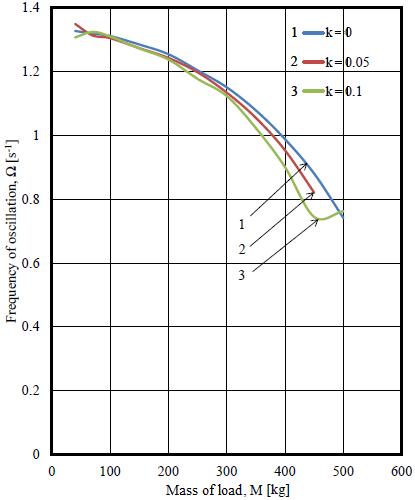
Figure 24Dependence of the frequency of oscillations of angular velocity on load mass in different values of coefficient of rotational friction and coefficient of sliding friction f=0.
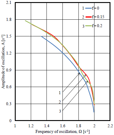
Figure 25Modulated amplitude frequency responses of oscillations of angular velocity of the driving link of mechanism in different values of coefficient of sliding friction and rotational friction k=0.
Graphs of dependence of angular velocity of rotation of driving links (engine shaft) and its torque, coordinates, velocity and acceleration projections of point C of working link on the time at different values of the coefficient of sliding friction and for coefficient of rotational friction k=0, and for the value of the load mass in working link M=500 kg which is similar to Eq. (44), when the power consumption of the mechanism is similar to power source strength (Fig. 18b) are presented in Figs. 18–21.

Figure 26Phase trajectories of the motion of a joint, connecting working platform with link in different values of rotational friction and with load mass of M=500 kg.
Comparison of graphs in Fig. 18 with graphs in Fig. 10a shows that a significant increase in load mass M leads to a significant decrease of minimum value and increase of maximum value of the angular velocity of driving link (engine shaft), as well as to decrease of its oscillations frequency. Effect of sliding friction on the angular velocity becomes significant at values of load mass M, similar to value (Eq. 44). With increase of the coefficient of sliding friction difference between maximum and minimum values of the angular velocity is increasing at constant average value, and the frequency of its oscillations decreases. This shows the significant effect of braking property of sliding friction.
Comparison of graphs of kinematic parameters in Figs. 19–21 with similar graphs in Figs. 15–17 shows that at moderate values of load mass in a working link change patterns of kinematic parameters are more similar to harmonic laws (except graphs Wy(t); Fig. 17), rather than at values of the load mass, close to the value (Eq. 44).
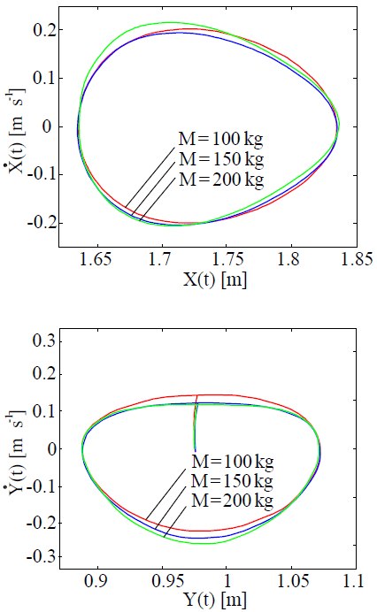
Figure 27Phase trajectories the motion of a joint, connecting working platform with link in different values of load mass and with the coefficient of rotational friction of k=0.1.
Upward shift in time of graphs of kinematic parameters is significant at increase of coefficient of sliding friction value. Load mass in working link reduces the frequency of kinematic parameters oscillations, occurs a considerable delay of movement and change of kinematic parameters at the time. Sliding friction affects the frequency of coordinate's oscillations, the oscillations frequency and maximum and minimum values of the velocity and acceleration projections. In this case it is possible to notice a significant demonstration of the nonlinearity in the time dependence of the kinematic parameters.
As in any nonlinear vibrational system in this system with linkage orthogonal mechanism and non-ideal source amplitude of vibrations depends on frequency of oscillations. Figure 22 shows graphs of dependence of amplitude on the frequency of oscillations of angular velocity of the driving link (engine shaft) A=A(Ω). Practical coincidence of the curves of amplitude -frequency responses in different values of coefficient of rotational friction means weak dependence AFR oscillations of angular velocity of the driving link (engine shaft) on the value of coefficient of rotational friction. Figure 23 shows linear dependence of the amplitude of oscillations of angular velocity on the load mass A=A(M) in different values of the coefficient of rotational friction. The larger is the load mass, the more influence of the coefficient of rotational friction on the frequency of oscillations of angular velocity of the driving link (engine shaft) (Ω=Ω(M) Relation on Fig. 24).
Graphs of dependence of modulated amplitude (MA) on the frequency of oscillations of angular velocity of the driving link (engine shaft) in different values of coefficient of sliding friction and of coefficient of rotational friction k=0 are shown in Fig. 25. It is possible to note the similarity of MAFR with f=0; 0.15; 0.20 and k=0 with similar graph with k=0; 0.05; 0.1 and f=0 (Fig. 22). With reduction of frequency, the influence of the coefficient of sliding friction on MAFR of angular velocity is manifested increasingly.
Analysis of phase trajectories of motion of joint, connecting the working platform with the link, shows that with increase in coefficient of rotational friction or load mass, the rate of ascent of the working platform decreases, and increases its rate of descent (Figs. 26 and 27). Studies of oscillograph records of angular velocity, coordinates of C point, as well as phase trajectories of this point show that, oscillations, corresponding to this point, are periodic and regular.
Thus, all highlighted above effects belong to excitation region of rotational movement of orthogonal mechanism, its boundaries are presented as an example in dependencies , , and are shown in Fig. 28.
From these graphs it is well observed that with an increase in the friction coefficients of sliding and rotation, the excitation boundary rises upward, in the direction of increasing the engine torque.
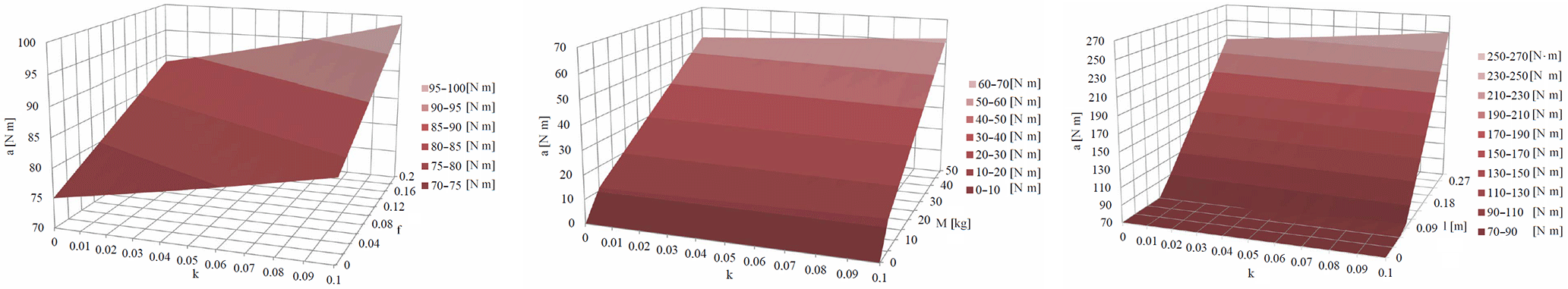
Figure 28Boundaries of the excitation region of the rotational movement of the driving link (engine shaft).
Based on the analysis and discussion of the results of the research the following conclusions can be drawn:
-
The effect of friction in kinematic pairs on the dynamics of the linkage mechanism with orthogonal motion in the presence of fixed load in the vibrating table is investigated.
-
It has been found that in each half-cycle the average value of the oscillating angular velocity of the driving link (engine shaft) depends on the coefficient of sliding friction.
-
The dependency graph of the amplitude of deviation of this angular velocity from its mean value on the coefficient of rotational friction is presented.
-
It is shown that both types of friction affect the maximum and the minimum value of the angular velocity per rotation cycle, by increasing the difference between these values. In this case the average value of angular velocity remains constant.
-
The dependence of the coefficient of non-uniformity of the driving link (engine shaft) rotation on the coefficients of friction has been established, according to which, by reducing these parameters sufficiently, it is possible to obtain an acceptable value of the coefficient of non-uniformity necessary for optimal design of vibrating table orthogonal mechanism with non-ideal energy source.
-
Effect of sliding friction on the amplitude and frequency of the angular velocity oscillations of the driving link (engine shaft) and on the frequency of the coordinate changes, and projections of velocity and acceleration of the hinge linking the working platform with coupler is determined.
-
The boundaries of the excitation region of the rotational motion as a function of the friction coefficients of sliding and rotation are determined.
The results of the investigations were used in preparing the application for obtaining a patent for the invention of a vibration table based on an orthogonal mechanism for developing a description, abstract and formula of invention. The inventive vibrating table can be used in the construction industry as a compactor for the liquid concrete platform, an platform of various suspensions, in pharmaceutics for mixing a liquid herbal drug suspension, and at flour mills and feed mills, groats plants for processing grain into food and feed products and in other industries.
Our main research results prior to this publication are stored in the following public data repositories: https://doi.org/10.2478/ijame-2014-0032 (Bissembayev and Iskakov, 2014), https://doi.org/10.1016/j.mechmachtheory.2015.05.011 (Bissembayev and Iskakov, 2015), https://www.degruyter.com/downloadpdf/j/ijame.2014.19.issue-3/ijame-2014-0032/ijame-2014-0032.pdf (Bissembayev and Iskakov, 2014) https://ru.scribd.com/document/269283064/1-s2-0-S0094114X15001159-main (Bissembayev and Iskakov, 2015), http://blog.espol.edu.ec/jpaezchavez/files/2015/08/ICoEV2015.pdf (Bissembayev and Iskakov, 2015).
From the geometry of Fig. 4, we have expressions for determining the coordinates of the hinge C
It is easy can make sure the validity the following relations
In the relations (Eq. A2), the angle φ2 expressing through the angle φ, substituting this value into the expressions (Eq. A1), we obtain
Differentiating the relations (Eq. A2), we have
whence
From the expressions (Eq. A3) we obtain
From the expressions (Eqs. A1 and A4) we find
ZI set a study objectives, participated in analysis and solving of differential equation of motion, prepared analysis of study results and manuscript for presentation; KB formed differential equation of motion and participated in the analysis of study results; NJ worked on numerical solution of differential equation of motion and participated in the analysis of the study results.
The authors declare that they have no conflict of interest.
The research work was funded by Ministry of Education and Science Republic of
Kazakhstan on the basis of the Grant Financing of Scientific Research 0501/GF (2012–2014)
and AP05134148 (2018–2020).
Edited by: Marek Wojtyra
Reviewed by: Konstantin Ivanov and one anonymous referee
Abdraimov, E. S., Kassymaliyev, B. M., and Bakirov, B.: About special aspects of mechanisms of variable structure by S. Abdraimov for creation of impact machines, in: Materials of VI International Conference of the Problem of Engineering of Modern machines, Ulan-Ude, 3–10, 2015.
Abrdaimova, N. S.: Articulation linkages with two special positions, Bishkek, Ilim, 2009.
Alifov, A. A. and Frolov, K. V.: Interaction of nonlinear oscillation systems with energy sources, Nauka, Moscow, 1985.
Balthazar, J. M., Mook, D. T., Brasil, R. M. L. R. F., Fenili, A., Belato, D., Felix, J. L. P., and Weber, H. I.: Recent results on vibrating problems with limited power supply, Meccanica, 330, 1–9, 2002.
Balthazar, J. M., Mook, D. T., Weber, H. I., Brasil, R. M. L. R. F., Fenili, A., Belato, D., and Felix, J. L. P.: An overview on non-ideal vibrations, Meccanica, 38, 613–621, 2003.
Bisembayev, K. and Iskakov, Z.: Mathematic model of the orthogonal mechanism of the press machine vibrating table, Bulletin of The Abay Kazakh National Pedagogical University, 3, 32 – 38, 2012.
Bissembayev, K. and Iskakov, Z.: Nonlinear vibrations of orthogonal mechanism of shaking table, Int. J. Appl. Mech. Eng., 19, 487–501, https://doi.org/10.2478/ijame-2014-0032, 2014.
Bissembayev, K. and Iskakov, Z.: Oscillations of the orthogonal mechanism with a non-ideal source of energy in the presence of a load on the operating link, Mech. Mach. Theory, 92, 153–170, https://doi.org/10.1016/j.mechmachtheory.2015.05.011, 2015a.
Bissembayev, K. and Iskakov, Z.: Mathematical modeling of the Mechanical system of the vibrating table with orthogonal movement and Hydraulic turbine with inclined blades, in: Proceedings of ICoEV 2015, 7–10 September 2015, Ljubljana, Slovenia, 38–47, 2015b.
Borisenko, L. A: Theory of mechanisms, machines and manipulators, Vyssheye Obrazovaniye, Moscow, 2011.
Cvetićanin, L.: Dynamics of the non-ideal mechanical systems: A review, J. Serb. Soc. Comput. Mech., 4, 75–86, 2010.
Dantas, M. J. H. and Balthazar, J. M.: On the appearance of a Hopf bifurcation in a non-ideal mechanical problem, Mech. Res. Commun., 30, 493–503, 2003.
Dantas, M. J. H. and Balthazar, J. M.: On local analysis of oscillations of a non-ideal and non-linear mechanical model, Meccanica, 39, 313–330, 2004.
Dimentberg, M. F., McGovern, L., Norton, R. L., Chapdelaine, J., and Harrison, R.: Dynamics of an unbalanced shaft interacting with a limited power supply, Nonlin. Dynam., 13, 171–187, 1997.
Dresig, H. and Golle, A.: Synthese sechsgliedriger Mechanismen fuer periodische Erregerkraefte, Getriebetechnik: Tradition und Moderne, Wiss. Zeitscyrift der TV, Dresden, 65–68, 2001.
Dresig, H., Naake, S., and Rockhansen, L.: Vollstandiger und harmonischer Ansgeleichebener Mechanismen, VD1 – Fortschrittbericht, VD1-Verlag, Düsseldorf, 18–155, 1994.
Felix, J. L. P., Balthazar, J. M., and Brasil, R. M. L. R. E.: On saturation control of a non-ideal vibrating portal frame founded type shear-building, J. Sound. Vib., 11, 121–136, 2005.
Frolov, K. V.: Scientific basis of vibration technology, in: Scientific basis of advanced technology, Mashinostroenie, Moscow, 157–220, 1982.
Frolov, K. V.: Mechanics and solution of machine-building problems, Adv. Mech., 11, 142–184, 1988.
Frolov, K. V. and Goncharevich, I. F.: Theory of vibration engineering and technologies, Nauka, Moscow, 1985.
Goldstein, G.: Classical Mechanics, Nauka, Moscow, 1975.
Gulyaev, V. I., Bazhenov, V. A., and Popov, S. L.: Applied Problems of the Theory of Nonlinear Oscillations of Mechanical Systems, Higher School, Moscow, 1989.
Jamalov, N. K. and Kamal, A. N.: Complex computer-aided synthesis and analysis of parallel linkages ASYAN, in: Proceedings of 6th International Conference – Issues of mechanics of the modern machines, 29 June–4 July 2015, Ulan-Ude, Russia, 68–72, 2015.
Kononenko, V. O.: Vibrating Systems with a Limited Power Supply, Izabranie trudi, Naukova dumka, Kiev, 1980.
Leonov, I. V. and Leonov, D. I.: Theory of Machines and Mechanisms, Vyssheye Obrazovaniye, Moscow, 2008.
Matveev, Y. A. and Matveeva, L. V.: Theory of Mechanisms and Machines, Alfa – INFRA, Moscow, 2009.
Tarabarin, V. B., Fursyak, F.I., and Tarararina, Z. I.: Studies of the moment of friction in rotational pair, Theory Mech. Mach., 10, 88–97, 2012.
Timofeev, G. A.: Theory of Mechanisms and Machines, PH URAIT, Moscow, 2010.
Tsuchida, M., Guilherme, K. D. L., Balthazar, J. M., Silva, G. N., and Cheshankov, B. I.: On regular and irregular vibrations of a non-ideal system with two degrees of freedom 1:1 resonance, J. Sound Vib., 260, 949–960, 2003.
Tsuchida, M., Guilherme, K. L., and Balthazar, J. M.: On chaotic vibrations of a non-ideal system with two degrees of freedom: 1:2 resonance and Sommerfield effect, J. Sound. Vib., 282, 1201–1207, 2005.
Tuleshov, E. A.: Dynamic analysis and design of mechanisms of automatic molding machines based on the crank machines, Dissertation of Candidate of Science Engineering, 5 February 2018, Almaty, 2010.
Zukovic, M. and Cveticanin, L.: Chaos in non-ideal mechanical system with clearance, J. Vib. Control, 15, 1229–1246, 2009.