the Creative Commons Attribution 4.0 License.
the Creative Commons Attribution 4.0 License.
 | 04 Feb 2026
Numerical analysis of the dynamic responses of submarine cable pallet under drop impacts considering the interaction between submarine cables and pallet
Yuze Wang
Lijie Zuo
Changfang Zou
Cong Li
Hongliang Zhang
Yi Luo
Yunfei Ding
Zechen Qian
Yuhe Zou
Pan Pan
Evaluating the dynamic responses of submarine cable pallets is of considerable importance in engineering applications. Nevertheless, an effective mechanical model to capture the dynamic responses of the pallet has yet to be developed. Therefore, a dynamic model of a submarine cable pallet was built, and the dynamic responses were studied in this paper. Elastic springs were arranged horizontally between the inner and outer fences. The objective was to replace the submarine cable with springs while accounting for the interaction between the submarine cable and the pallet during the falling process. First, the necessity of incorporating the submarine cable into the model was validated through analyzing the dynamic responses of the pallet under varying submarine cable mass conditions. Subsequently, the dynamic responses of the pallet under various falling postures were examined, with a focus on the effects of fall velocity and angle. Finally, the dynamic stability of the pallet was determined based on displacement mutation criteria during the falling process. The results demonstrated that the displacement of the pallet web plate initially increased and subsequently decreased with the increase in submarine cable mass, whereas the displacement of the fence exhibited a clearly upward trend. Both fall velocity and angle exerted significant influences on the dynamic responses of the pallet. In conclusion, this study provided a theoretical foundation and practical reference for the stability assessment and engineering application of submarine cable pallets.
- Article
(11485 KB) - Full-text XML
- BibTeX
- EndNote


Collision, falling, explosion and other similar conditions may elevate the risk of dynamic instability in ships and marine structures, potentially resulting in catastrophic failure. Therefore, it was crucial to evaluate the dynamic stability. In many design criteria for marine structures, the evaluation of stability and ultimate strength were typically conducted under static loads, and the local safety factor was introduced to mask the dynamic effects, which ignored the plastic strengthening of materials (Polizzotto, 2010) and stress wave effects (Clifton, 1985). Currently, several criteria for determining the dynamic buckling critical state – including the B-R criterion (Rostamijavanani, 2020), the energy method (Xin and Han, 2020) and the plate thickness criterion (Volmir, 1972) – had been proposed. Moreover, numerous studies have been carried out on the dynamic stability of marine structures. Zhang (2013) pointed out that both geometric non-linearities and material plasticity should be taken into account when assessing the ultimate strength of the hull beam. Traditional quasi-static methods may overestimate dynamic stability by as much as 40 %. The progressive collapse of a container ship under wave loading was characterized by three distinct stages: “local buckling, plastic hinge formation and overall instability”. Furthermore, fluid–structure interaction (FSI) resulted in a 27 % increase in the peak hull moment (Zhou et al., 2023). Significant spatial variability was observed in the dynamic responses induced by oblique collisions through truncated hull asymmetric thumping experiments. The equivalent plastic strain in the midship region was 41 % higher than that in the stern structure, and the stress wave propagation exhibited anisotropic characteristics (Xie et al., 2020). Moreover, the influence of parameters such as the amplitude of thumping pressure, impact duration and pressure rise time on the dynamic responses of the bow structure was analyzed, and a “safety margin factor” was proposed to assess the structural safety of the container ship under thumping pressure loading (Yang and Wang, 2018). As the main bearing structure of the ship, the dynamic buckling behavior of the deck directly affected the overall safety. It has been demonstrated that deck grillage structures are susceptible to dynamic buckling under blast impact loads, which may lead to hull collapse (Kong et al., 2021). In this respect, the effects of load forms, load period, initial deflection and plate length fineness on the dynamic buckling of hull plates were analyzed, and the B-H criterion was applied to determine the critical buckling points. Taking various influencing factors into account, a formula for the critical dynamic buckling load was established (Yan et al., 2023). In the study of U-shaped corrugated sandwich panels under varying impact velocities and positions, it was found that both impact velocity and position significantly influenced the dynamic responses and damage characteristics of the panels. The transverse impact resistance of the sandwich panels was found to be superior to the longitudinal impact resistance, attributed to the structural configuration of U-shaped corrugated sandwich panels (Cheng et al., 2022). Based on the theory of large deflection in thin plates, the dynamic buckling behavior of elastic rectangular plates with torsional restraints under in-plane thumping loads was investigated using Galerkin's method. A comprehensive investigation was carried out to examine the effects of initial imperfections and thumping duration on the dynamic responses and buckling behavior of rectangular plates (Yang and Wang, 2017). Reinforced plates represent a critical component of marine structures. Based on the theory of large deflections in plates, the effects of rotational constraint stiffness, initial imperfections and the loading period on the dynamic responses of edge-elastically constrained plates under in-plane impact loading were investigated (Yang and Wang, 2016). By conducting a drop hammer impact load test on the reinforced plate, the variation pattern of the web plate's lateral displacement with respect to impact velocity was obtained, thereby validating the rationality of determining the critical impact velocity using the B-R and plate thickness criteria (Shi et al., 2023). Based on the theory of large deformations, an analytical method was proposed to accurately predict the critical buckling strength of reinforced plates under impact loads by separating the displacement functions of the plate and the reinforcement (Xiong et al., 2023).
Circular pipe structures serve as fundamental components that are widely utilized in marine engineering. The dynamic responses of cylindrical shell support structures under multiple impact loads were thoroughly investigated. The effects of impact peak acceleration, top counterweight and thickness-to-diameter ratio of the cylindrical shell were analyzed through numerical simulations. Empirical equations describing the variation patterns of cylindrical shell deflection and inclination under different influencing factors were derived based on multiple experimental trials (Zhu et al., 2024).
Through experiments conducted on pipes with variable wall thickness, Amini et al. (2020) observed that the first-order natural frequency increased by approximately 8 % for every 10 % increase in the circumferential wall thickness gradient. The axial gradient variation induced coupled vibrations predominantly governed by higher-order modes. The effects of the dimensionless hull impact factor, length-to-slenderness ratio and localized annular reinforcement on the dynamic plastic buckling behavior of cylindrical shells under underwater blast loads were examined (Nie and Zhang, 2022). The stability of metallic cylindrical shells was examined by taking into account the combined effect of initial hydrostatic pressure and dynamic pressure pulses (Gupta et al., 2016). Additionally, box-type structures have also been widely adopted in marine engineering applications. Through numerical simulations of rigid and elastic box-shaped structures, the effects of wave impacts on such structural configurations were systematically investigated (Yang et al., 2023). The dynamic responses of box girder bridge superstructures under extreme wave loading conditions were examined (Huang et al., 2024). Currently, most studies on the dynamic stability of marine structures have been based on simplified models such as single plates, beams and tubes, which fail to account for the complexity inherent in actual marine structures. Therefore, the dynamic responses of sea cable pallets, considering the coupled effect of the sea cable and the fence, were analyzed using the finite element method (FEM). The effects of submarine cable mass, fall velocity and fall angle on the dynamic responses of the pallet base and fence were investigated separately.
2.1 Basic parameters and material constitutive model of pallet
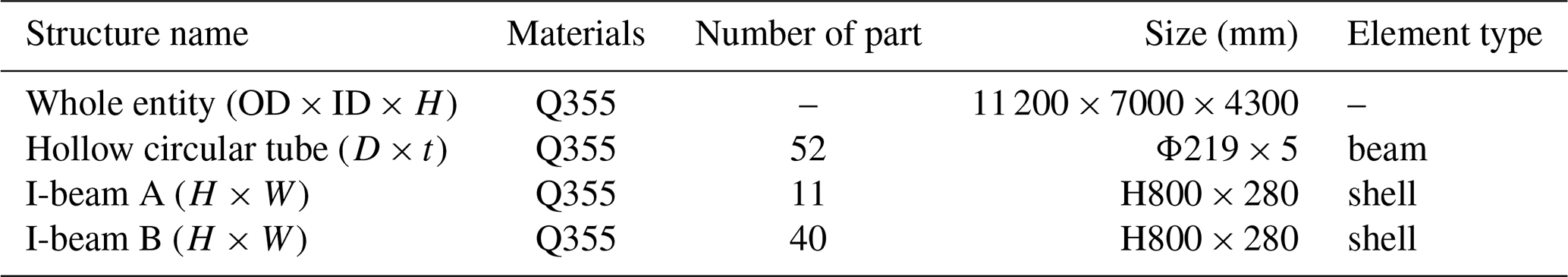
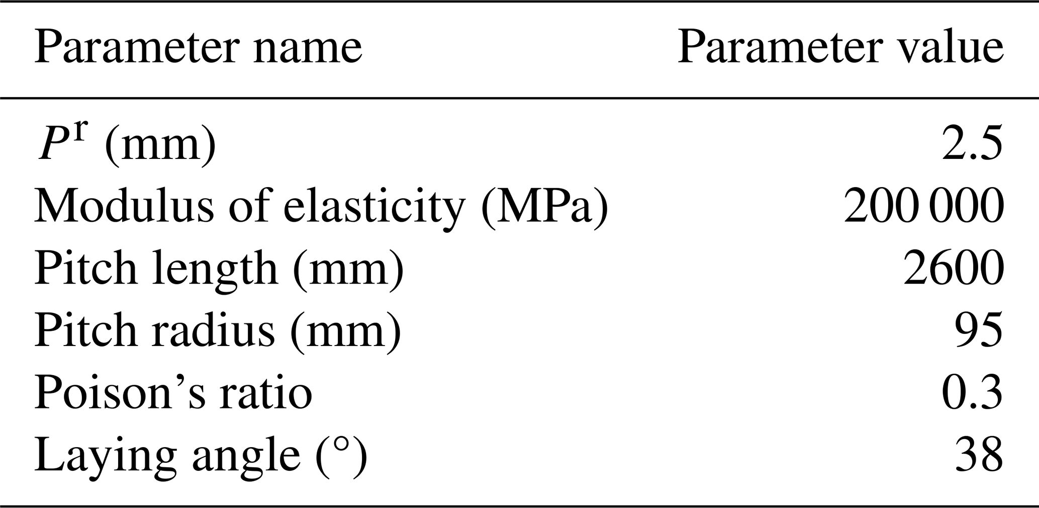
The research object of this paper is the submarine cable pallet with a maximum loading capacity of 400 t, which consists of two components: the fence and the base. The basic parameters of the finite element model are presented in Table 1.
Table 1Pallet basic parameters with the mass bearing capacity of 400 t.
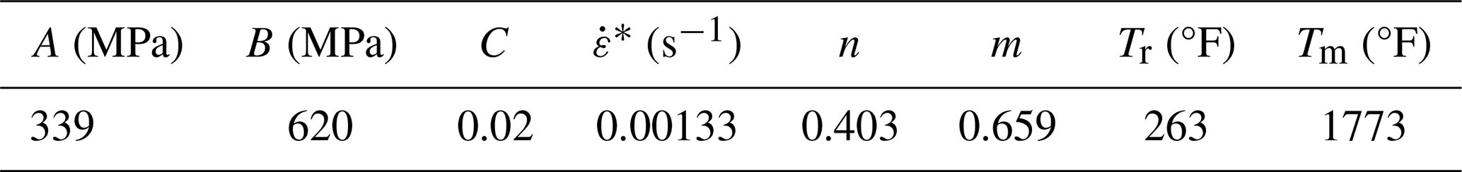
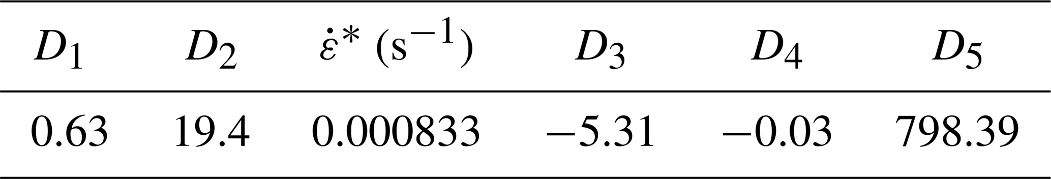
The yield strength of materials increased with the strain rate under dynamic loading conditions, which was known as plastic strengthening. The Johnson–Cook (J–C) equations were commonly used to describe this phenomenon in the numerical model. The basic form of the J–C constitutive are shown as Eqs. (1) and (2):
where A, B, n, C, m, D1, D2, D3, D4 and D5 are material constants; is the equivalent plastic strain; is the equivalent plastic strain rate; T is the melting temperature, defined as ; Tm is the melting temperature; Tr is the room temperature; and T0 is the current temperature.
The parameter values of the J–C equation for Q355B steel are listed in Tables 2 and 3.
2.2 Mechanical properties of submarine cables
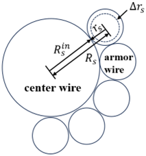
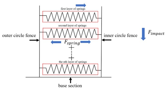
The submarine cable consists of core conductors, a shield layer, an insulation layer, a sheath layer, an inner liner layer, an armor layer and an outer covering layer. The submarine cables are closely constrained by the inner and outer fences of the pallet when placed on it. Upon the pallet falling, the submarine cables undergo radial deformation, which inevitably results in additional impact on the inner and outer fences. Simultaneously, the submarine cable absorbs impact kinetic energy during radial deformation, thereby influencing the energy distribution of the pallet. Therefore, it is essential to consider submarine cables when the pallet falls. Typically, the armor layer is composed of steel and distributes the major external forces, thereby providing protection to the core conductors of submarine cables. The radial deformation observed in the armor layer can represent that of the submarine cables, and the magnitude of deformation is determined by the radial stiffness of the armor layer. A simplified structure of submarine cables is illustrated in Fig. 1, which depicts the deformation condition of the submarine cable. In this study, the submarine cables were modeled as elastic springs within the FEM model. The radial stiffness of the submarine cables was derived by calculating the radial stiffness of the armored wire. In the FEM model, the springs were horizontally oriented and connected to the inner and outer fences, respectively.
The effects of submarine cable armor wire pitch and pallet diameter on the axial mechanical behavior of submarine cables were investigated through numerical analysis (Chae et al., 2023). These equations regarding the axial stress and strain in the armor wire of the submarine cables, which were obtained from it and were used in this paper, are presented as follows:
where R is the armor wire pitch radius, L is the armor wire pitch length, pr is the radial component of the armor wire central cross-section vector P, s is the cross-sectional area of the armor wire, E is the elasticity model of the armor wire, Δkr is the change of the armor wire curvature when the submarine cable is subjected to an external force and kr is the armor wire curvature under the submarine cable without external force.
The formulas for the radial pressure PS and the total strain ε of a sea cable (McNamara and Harte, 1992) are presented as follows:
where M is number of armored wires laid on one submarine cable, Fs is the armor wire axial force, Δu is the armor wire axial deformation, Δrs is the armor wire radial deformation, L is the length of the armored wire per unit pitch, Rs is the distance from the armor wire center to the center wire, is the radius of the center wire and α is the helix angle of the armor wire.
The relationship between the axial strain and the total strain of the armored wire (Chang and Chen, 2019) is shown in Eq. (9).
As a result, the mechanical relationship between the axial and radial directions of the armor wire could be established.
In this study, the parameter values of the submarine cable armor wires were selected according to the reference (Chae et al., 2023), is shown in Table 4.
Table 4Basic parameter values of conventional submarine cable armor wires.
The spring stiffness can be calculated by Eq. (10):
where Kn is the elastic stiffness of the spring, Δx is the spring deformation, s is the cross-sectional area of the spring and P is the spring axial stress.
Based on the equations and data mentioned above, the submarine cable radial deformation, submarine cable radial stress and the contact area of the single-layer submarine cable with the fence were obtained. If the submarine cables were modeled as springs, Δx could be regarded as the radial deformation of the armor wire, s could be regarded as contact area of the single-layer submarine cable with the fence and P could be regarded as the radial stress of the armor wire. Therefore, the spring stiffness value representing the single-loop submarine cable could be determined.
It can be seen from the above test that the maximum number of the submarine cable coiling was 12. In this study, the equivalents of 12 springs with different stiffness values were connected in series, which was equivalent to a linear spring with stiffness K, as shown in the following equation:
The calculation process is as follows:
The spring stiffness K that the pallet velocity must exceed was about 27.56 kN mm−1.
The mass of the submarine cables was modeled as mass points, which were uniformly distributed on the upper surface of the pallet base. The pallet model is illustrated in Fig. 2.
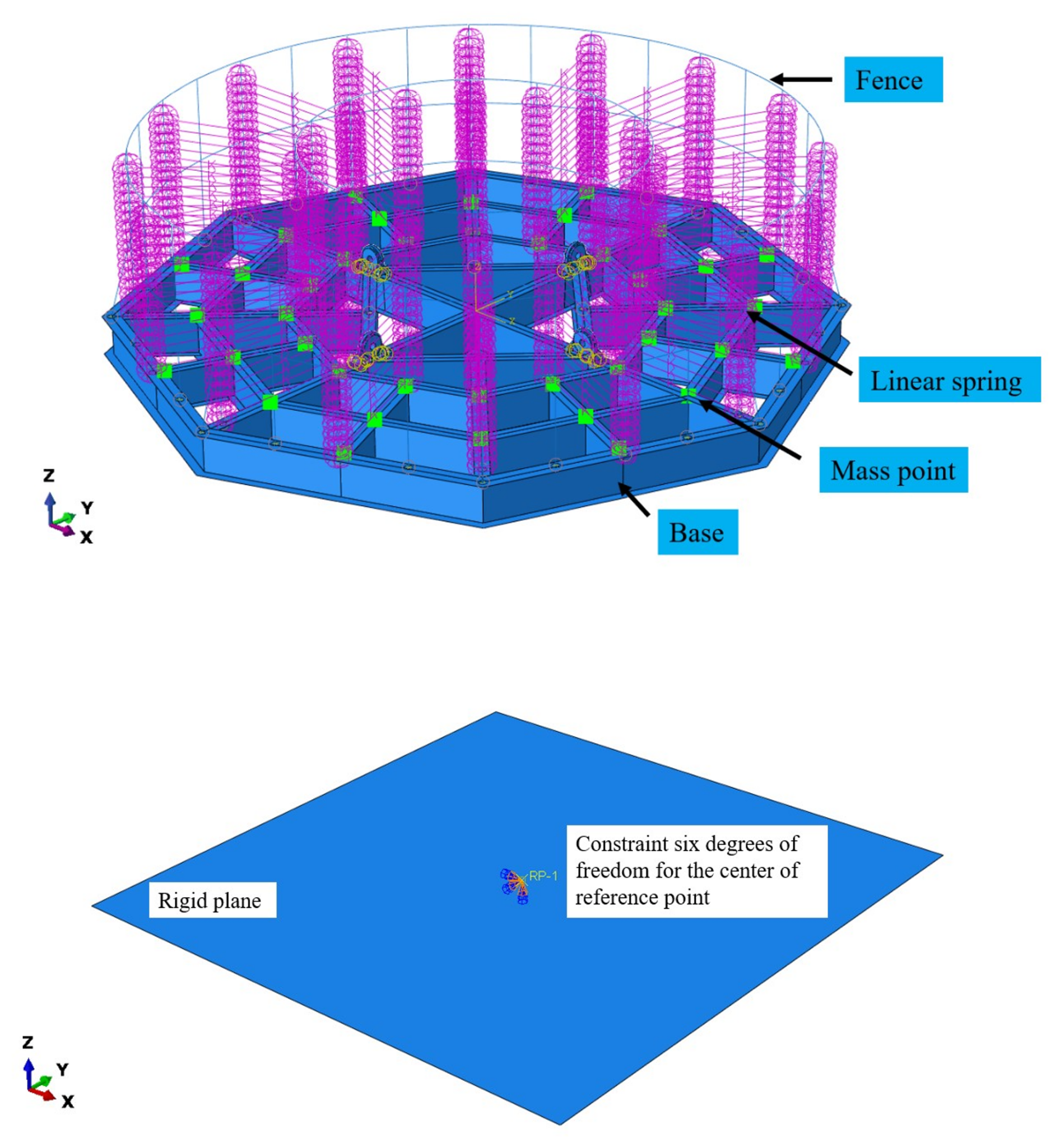
The radial stiffness of the submarine cable was simplified and equated to the elastic stiffness of a linear spring, horizontally connecting the inner and outer fences of the pallet. The weight of the submarine cables was modeled as 40 mass points, which were distributed across the upper surface of the pallet base. Each layer of linear springs represented one layer of submarine cable located between the inner and outer fences. When the pallet was fully loaded, 16 layers of linear springs were attached, representing 16 layers of submarine cables. A planar rigid body was defined as the ground, with a reference point established at its center of mass, including associated mass and constraint conditions.
3.1 Dynamic responses of pallet drop with different submarine cable mass
In practical engineering applications, the mass of submarine cables can significantly influence the dynamic responses of the pallet system, which corresponds to variations in the mass distribution and the number of springs within the finite element model (FEM). Investigating the dynamic responses of the pallet under varying conditions was deemed valuable. Accordingly, the dynamic performance of pallet drop was examined under different submarine cable mass scenarios. Table 5 presents the relevant loading mass parameters that were selected for the study of pallet dynamic responses.
Table 5Correspondence between loading mass and the number of mass points and spring layers.
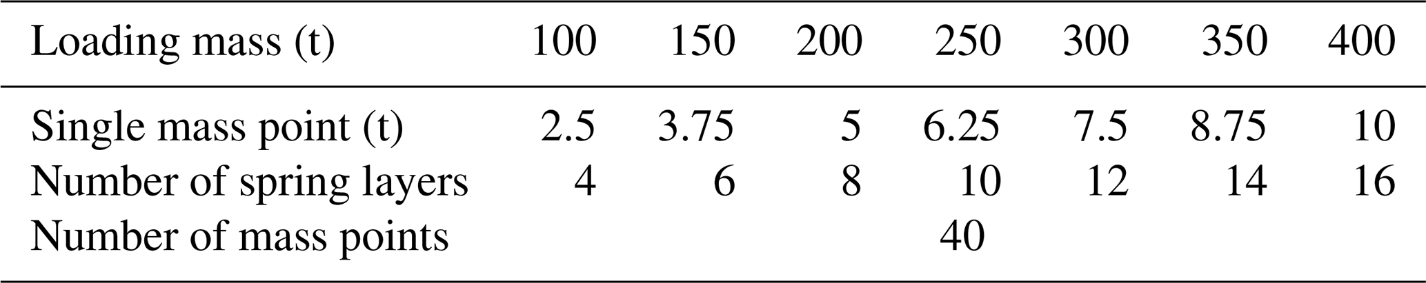
According to DNV-ST-E273, the pallet velocity must exceed 1 m s−1 at the moment of collision. Therefore, in this study, the initial velocity of the pallet was set to 1 m s−1. The distance from the rigid body plane to the pallet was defined as 50 mm, and the initial posture of the pallet was assumed to be horizontal. The variations in the energy distribution of submarine cables, as well as the dynamic responses of the pallet base and fence, were analyzed.
3.1.1 Energy distribution of the pallet
Figure 3 illustrated the variation of pallet strain energy and kinetic energy over time under different submarine cable mass conditions. As indicated, Table 6 presents the strain energy and kinetic energy data of the pallet under loading masses ranging from 100 to 400 t for submarine cables.
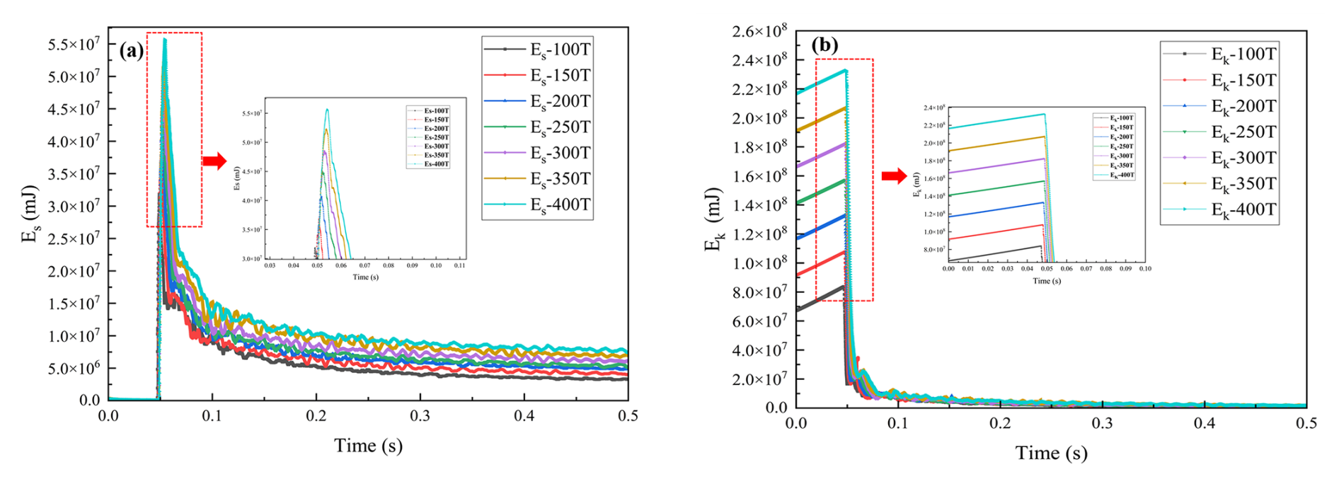
Table 6Energy for falling pallet with different submarine cable mass.
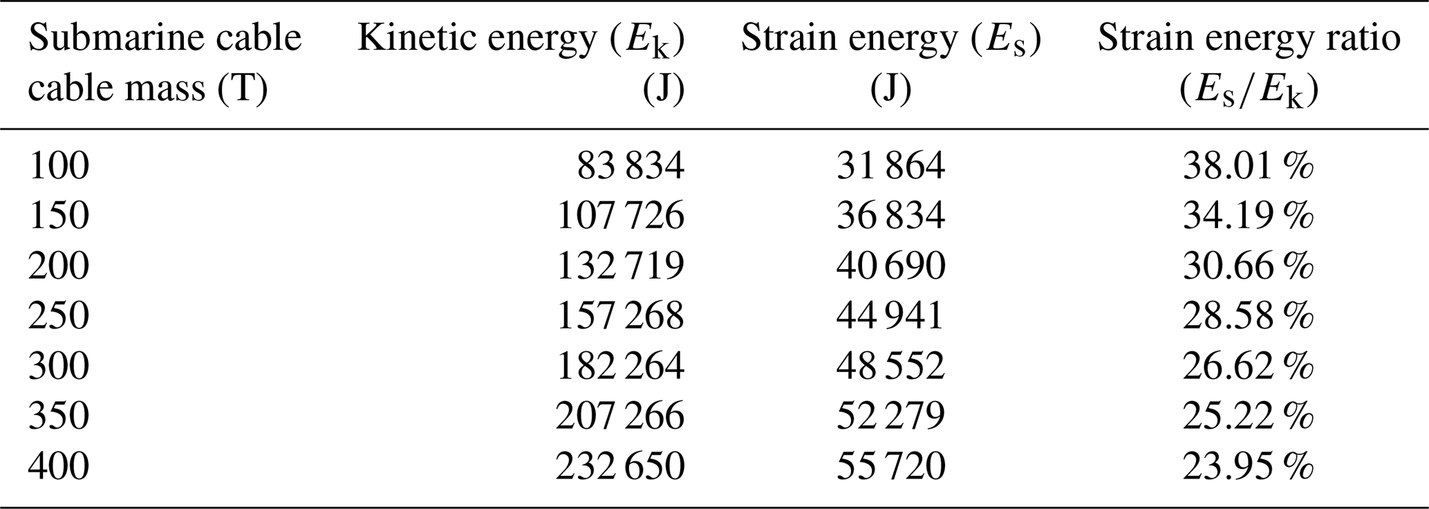
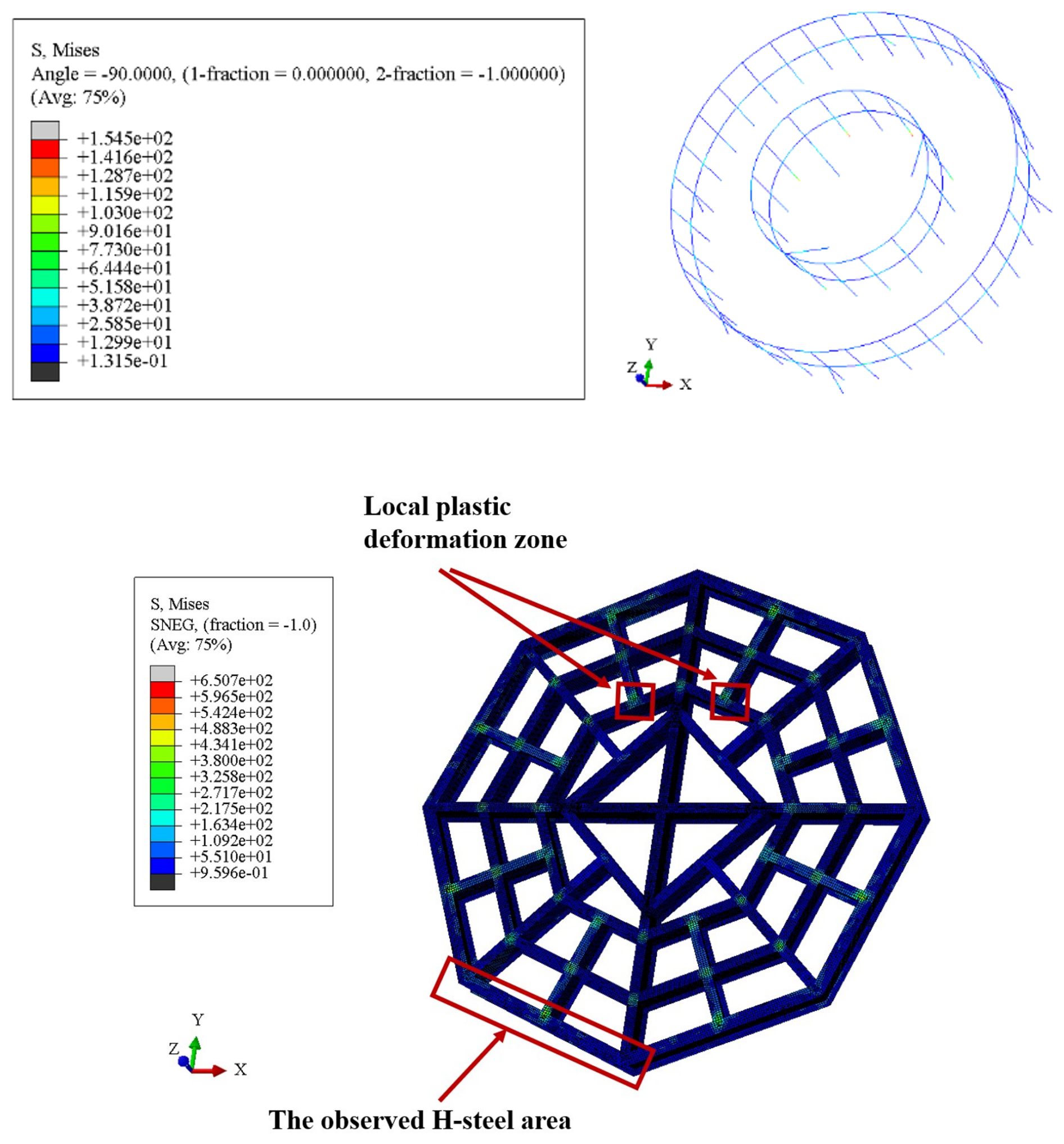
It can be observed that as the pallet loading mass increased, the proportion of kinetic energy converted into strain energy continuously decreased, while a greater portion was transformed into internal energy. The stress distribution of the pallet after it had fallen is illustrated in Fig. 4. Although the overall stress of the pallet remained below the yield threshold and resulted in elastic deformation, a significant amount of plastic work was generated in the connection region between the base and the fence. At the same time, the outermost web plate of the pallet base was subjected to greater bending moments due to reduced constraint and decreased web plate thickness, making it a critical area for the study of web plate dynamic responses during pallet fall under a horizontal initial condition.
3.1.2 Dynamic responses of pallet base web plate
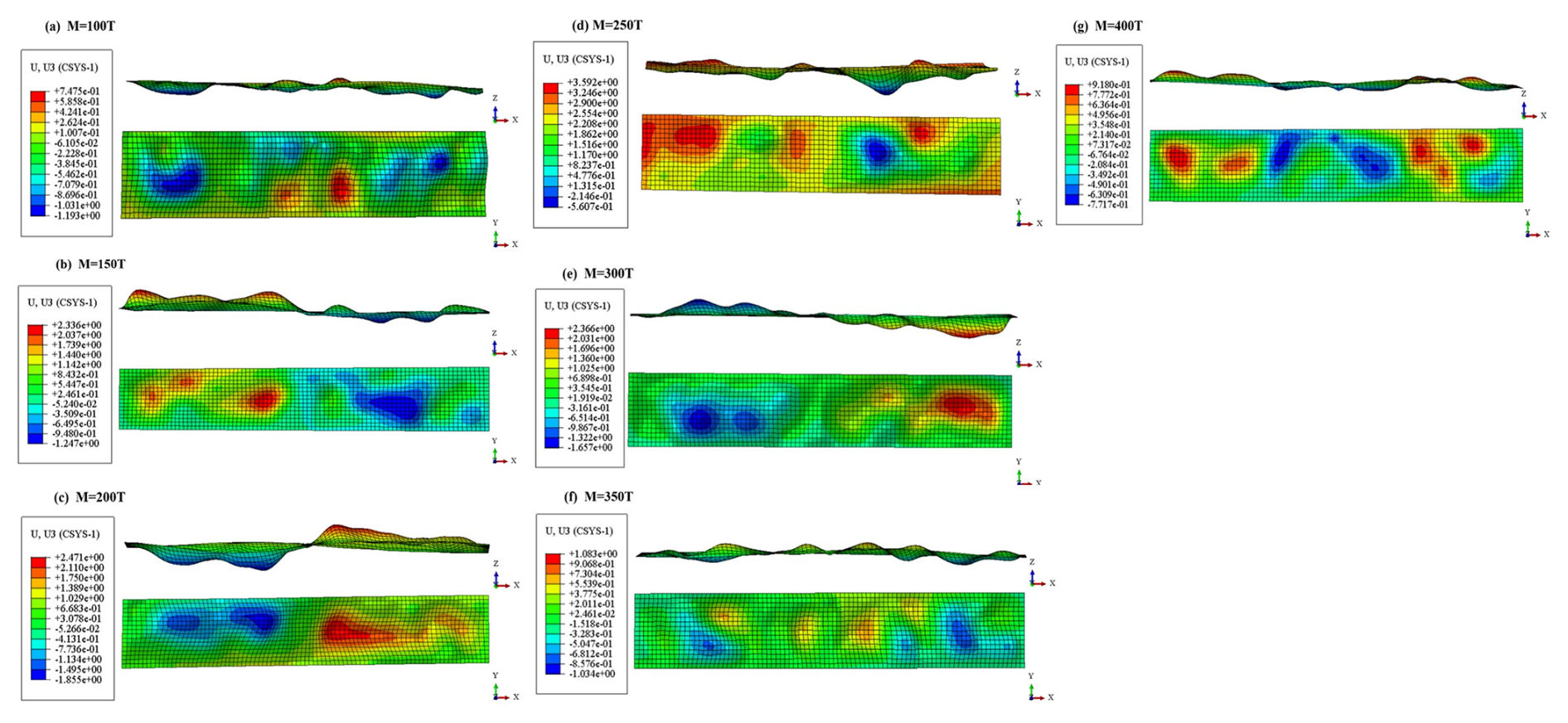
The displacement contour maps of the outermost web plate under varying mass points are presented in Fig. 5. As observed in the contour maps, the web plate displacement initially increased and subsequently decreased when the mass exceeded 250 t. Furthermore, a larger web plate displacement was associated with a reduction in the number of deformation waves along the web plate.
As shown in Fig. 6, assuming the springs had n layers, the total stiffness of the all layers' springs is
The axial deformation of all layers' springs is
The elastic potential energy of all layers' springs is
Assuming that the spring efficiency in absorbing kinetic of the pallet energy is η,
thereby,
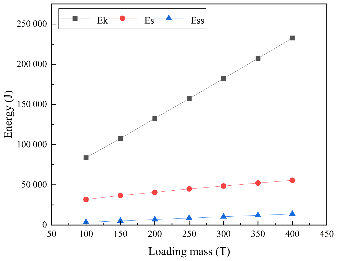
The falling velocity remained constant. As shown in Table 6, the kinetic energy of the pallet (Ek) increased linearly with the mass point, while the total strain energy (Es) increased non-linearly at a slower rate, resulting in a gradual decrease in the ratio. The total strain energy Es comprised the spring strain energy (Ess) and the pallet strain energy (Esp). The variation in system energy is illustrated in Fig. 7. The value of Ess increased linearly with the mass point, as described by Eq. (14). Therefore, the value of Es − Ess first increased and subsequently decreased, indicating that the deformation of the base web plate initially increased and then decreased, which is consistent with the results obtained from the web plate displacement contour maps presented in Fig. 5.
3.1.3 Dynamic responses of pallet fence
In this study, it is assumed that the submarine cable underwent only radial elastic deformation. Consequently, the linear springs were modeled without damping. Upon impact, the pallet fence bent due to the inertial force generated by the impact and the axial force exerted by the springs. The spring axial force increased with the mass point, as expressed in Eq. (17), and the response curves of time versus pallet fence lateral displacement are presented in Fig. 8.
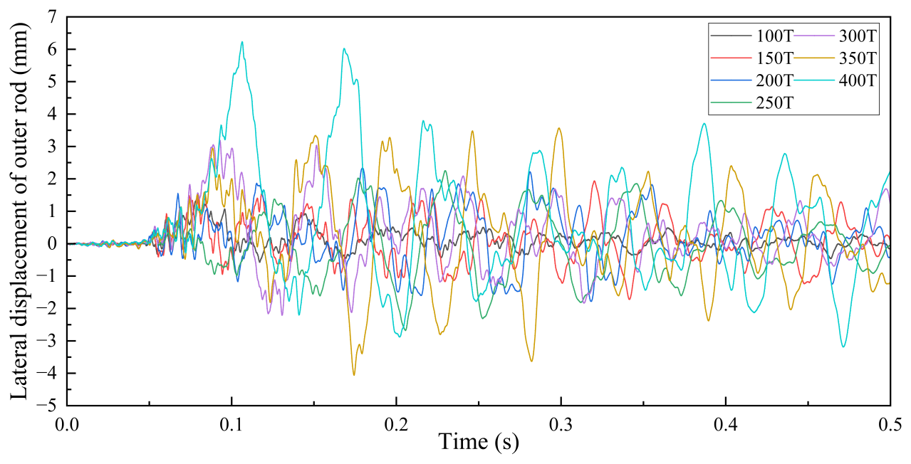
Figure 8Response curves of time versus pallet fence lateral displacement under different submarine cable mass.
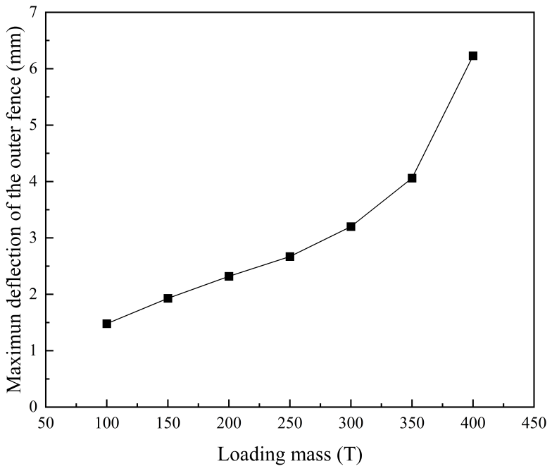
Based on Fig. 8, the line chart of fence maximum lateral displacement versus submarine cable mass is presented in Fig. 9. It is evident that the lateral displacement demonstrates a non-linear increase with respect to the submarine cable mass. After the submarine cable mass reached 300 t, the lateral displacement of the pallet fence increased rapidly, indicating elastic buckling of the fence.
3.2 Dynamic responses of pallet fall at horizontal initial state
3.2.1 Dynamic responses of the pallet base with different impact velocities
Impact velocity was a critical factor in the study of the dynamic responses of the pallet. The increase in velocity enhanced the kinetic energy of the pallet, thereby influencing structural stability. The bottom surface of the pallet base made full contact with the ground when falling from a horizontal initial state. The impact force acted vertically on the entire bottom surface of the pallet base, generating a uniformly distributed compressive force. The web plate was the primary component subjected to axial compressive force. Numerous studies have demonstrated that plate and shell structures are susceptible to failure when subjected to high-velocity impacts or high accelerations. Therefore, it is valuable to investigate the effect of velocity on the dynamic responses of the pallet base web plate. In this study, the mass of the submarine cables was set to 250 t. The initial drop velocities were set to 1, 2, 4, 5, 6, 8, 10 and 12 m s−1 in the following six groups of the model, respectively. The displacement contour maps of the web plate after the pallet falling are shown in Fig. 10.
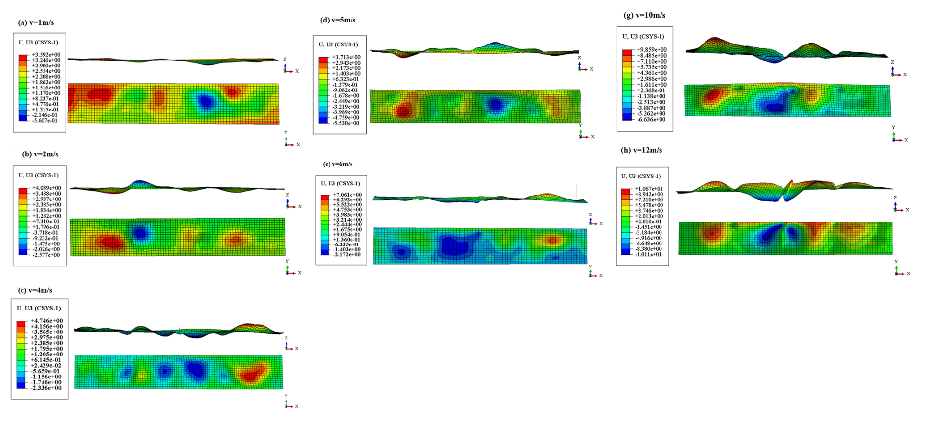
Figure 10Lateral displacement cloud of the pallet base web plate with different impact velocities at the horizontal initial state.
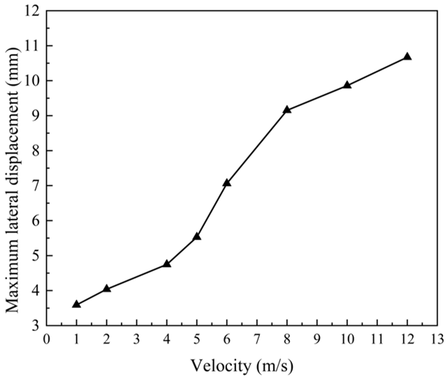
As illustrated in Fig. 10, the maximum lateral displacement of the web plate occurred in the central region, exhibiting one or two fully developed deformation waves. Higher velocities correspond to larger wave amplitudes. The velocity–displacement relationship of the web plate is illustrated in Fig. 11. As shown in Fig. 11, the lateral displacement of the web plate base increased gradually when the initial drop velocity was below 5 m s−1. A sharp increase in lateral displacement occurred once the initial velocity reached 5 m s−1. When the velocity continued to rise beyond 8 m s−1, the growth rate of the web plate lateral displacement became gradual again. The displacement mutation criterion indicated that buckling occurred when the lateral displacement undergoes a sudden change in to velocity. Accordingly, it can be determined that buckling of the web plate takes place when the pallet falls with an initial velocity of 5 m s−1.
3.2.2 Dynamic responses of the pallet fence with different impact velocities
The failure modes of the pallet fence varied under different initial velocities. When the impact velocity did not exceed 12 m s−1, lateral displacement was observed at the mid-section of the fence, as shown in Fig. 12a. When the impact velocity reached 15 m s−1, as shown in Fig. 12b, severe bending at the fence root was observed, indicating a potential fracture of the fence. To determine whether the deformation of the fence induced dynamic buckling, the lateral displacement of the mid-section of the fence under different velocities was measured. The displacement–time curve of the fence under different initial velocities is presented in Fig. 13.
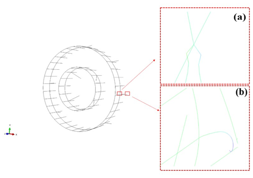
Figure 12Different failure modes of the fence: (a) deformation of the fence middle part and (b) deformation of the fence root part.
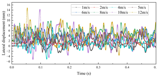
Figure 13Response curve of the fence displacement versus time with different initial velocities.
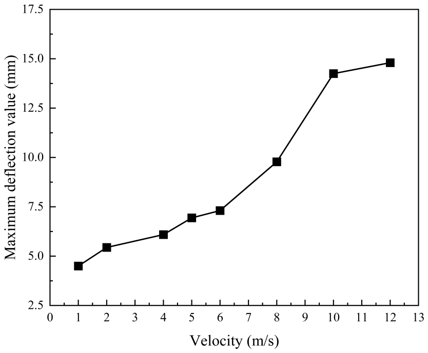
The lateral displacement–velocity chart of the fence is illustrated in Fig. 14. As shown in Fig. 14, the lateral displacement of the fence increased gradually when the initial falling velocity was below 8 m s−1. The lateral displacement of the fence increased sharply when the initial falling velocity reached 6 m s−1. However, the rate of change in lateral displacement stabilized again when the initial velocity exceeded 10 m s−1. It was determined that dynamic buckling of the fence occurred when the initial falling velocity reached 6 m s−1, as the slope of the curve increased abruptly.
3.3 Dynamic responses of pallet at slanted initial state
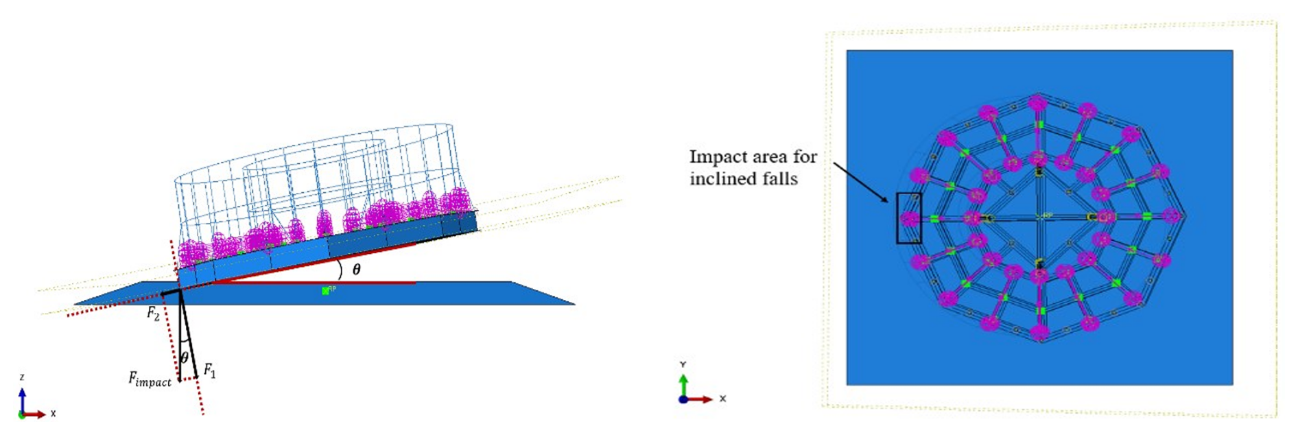
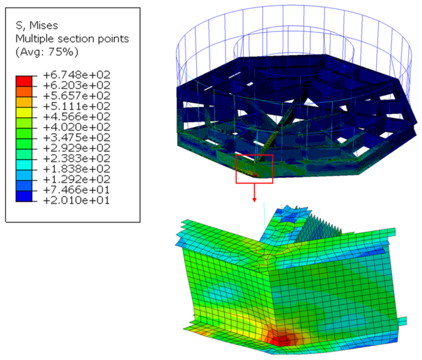
The impact area of the pallet under slanted initial conditions is shown in Fig. 15. Compared with the horizontal initial conditions, the variation in impact area results in differences in impact force distribution, stress distribution and energy transfer pathways. The impact occurred when the edge of the base flange contacted the ground, resulting in concentrated impact forces and the formation of an asymmetric load within the impact region. The F1 component of the impact force induced localized compression and bending in the base flange. The F2 component generated shear forces and bending moments, thereby increasing the local high stress within the impact region. During the pallet's fall under slanted initial conditions, the stress in the impact region exceeded the yield stress significantly, confirming the occurrence of plastic deformation in that area. As illustrated in Fig. 16, the stress distribution of the pallet under slanted initial conditions was significantly different from that of the pallet under horizontal initial conditions.
In this study, the dynamic responses of the pallet impact area under slanted initial conditions were examined from two perspectives (impact velocity and impact angle) using finite element analysis. Since the displacement did not accurately represent the actual deformation of the pallet under slanted initial conditions, logarithmic strain values were utilized to characterize the deformation of the web plate and flange within the impact region.
3.3.1 Dynamic responses of the pallet base with different impact velocities
The impact angle was set to 10°, and the initial velocities of the pallet were set to 1, 2, 3, 4 and 5 m s−1, respectively. The curves of the web plate and flange logarithmic strain values versus time are shown in Fig. 17.
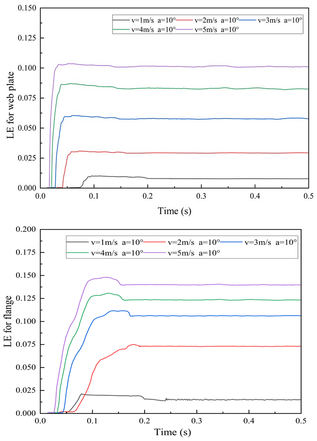
As observed in Fig. 17, the web plate and flange underwent deformation, and the strain increased rapidly upon impact. Due to high stress, the web plate and flange appeared plastically strengthened in a short time. The rate of strain value change decreased and eventually stabilized after reaching peak values at 0.1 s. The strain distribution contour maps of the web plate and flange in the impact region are presented in Fig. 18.
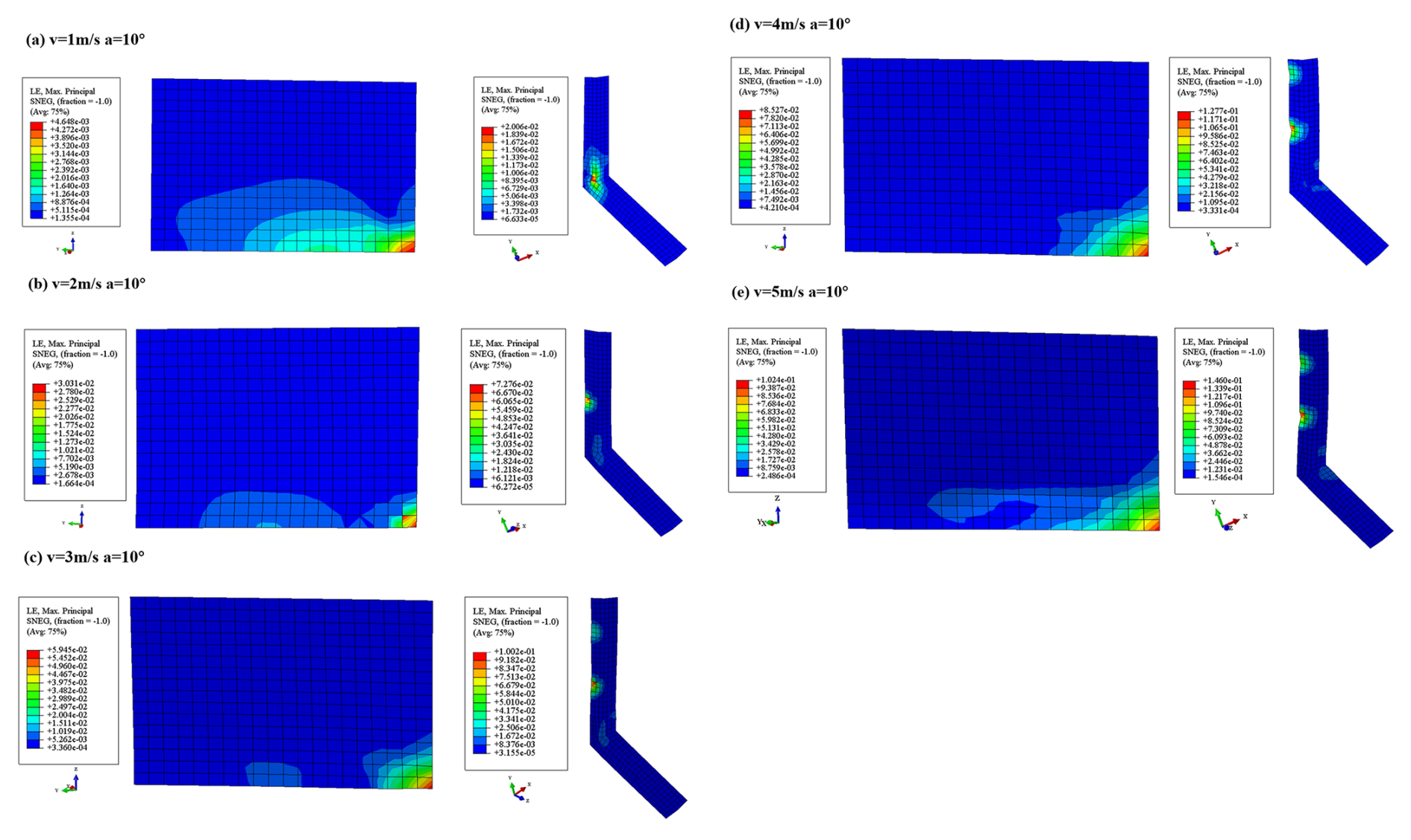
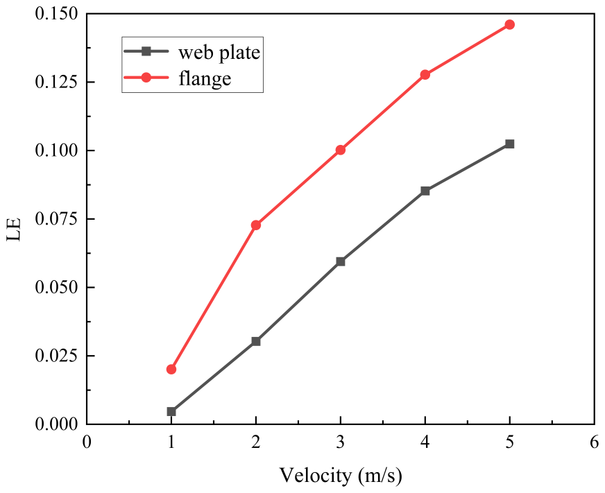
The strain versus velocity curves of the web plate and flange in the impact area are shown in Fig. 19. Compared to the web plate in the impact area, the flange in the impact area experienced a greater impact force when the pallet fell under slanted initial conditions. As a result, a greater amount of impact force was converted into plastic energy within the flange. Consequently, the strain experienced by the flange was higher compared to that of the web plate. As shown in Fig. 19, the strain rate in the web plate and flange decreased with increasing impact velocity. It is reasonable to assume that the base structure remains stable under all the aforementioned conditions.
3.3.2 Dynamic responses of the pallet base with different impact angles
In this part, the initial velocity was 5 m s−1. The pallet initial impact angles were 5, 10, 15, 20 and 25°, respectively. The strain versus time curves of the web plate and flange are shown in Fig. 20. The contour maps of the web plate and flange logarithm strain in the impact area are presented in Fig. 21.
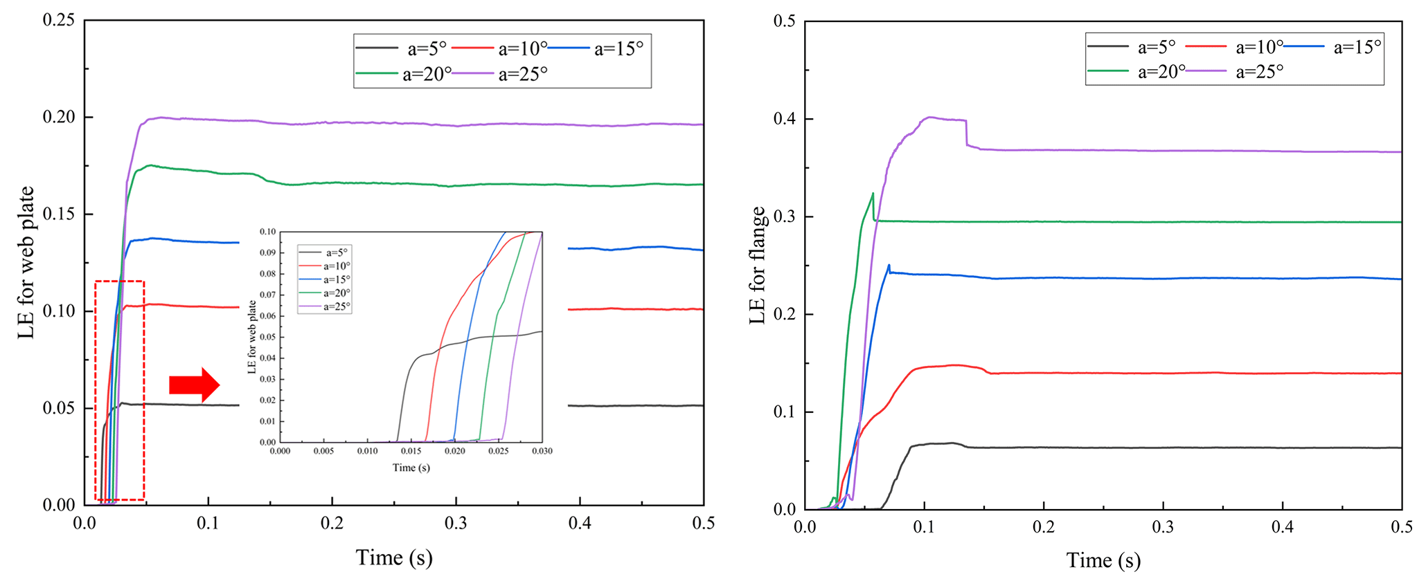
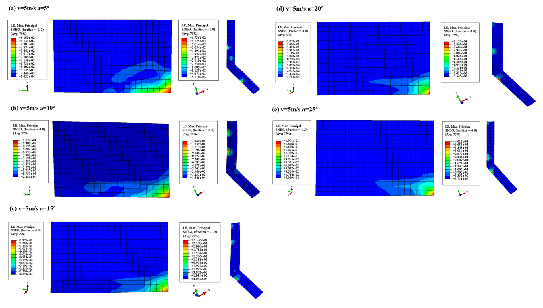
As the impact angle of the pallet increased, the concentrated impact force per unit area on the flange increased accordingly. As illustrated in Fig. 21, deformation was observed along the edge of the flange. As the impact angle increased, the deformation value increased and progressively approached the bending region of the flange. Furthermore, although the deformation value of the web plate increased, the deformation extent gradually decreased. Consequently, high stress within the impact region became more pronounced.
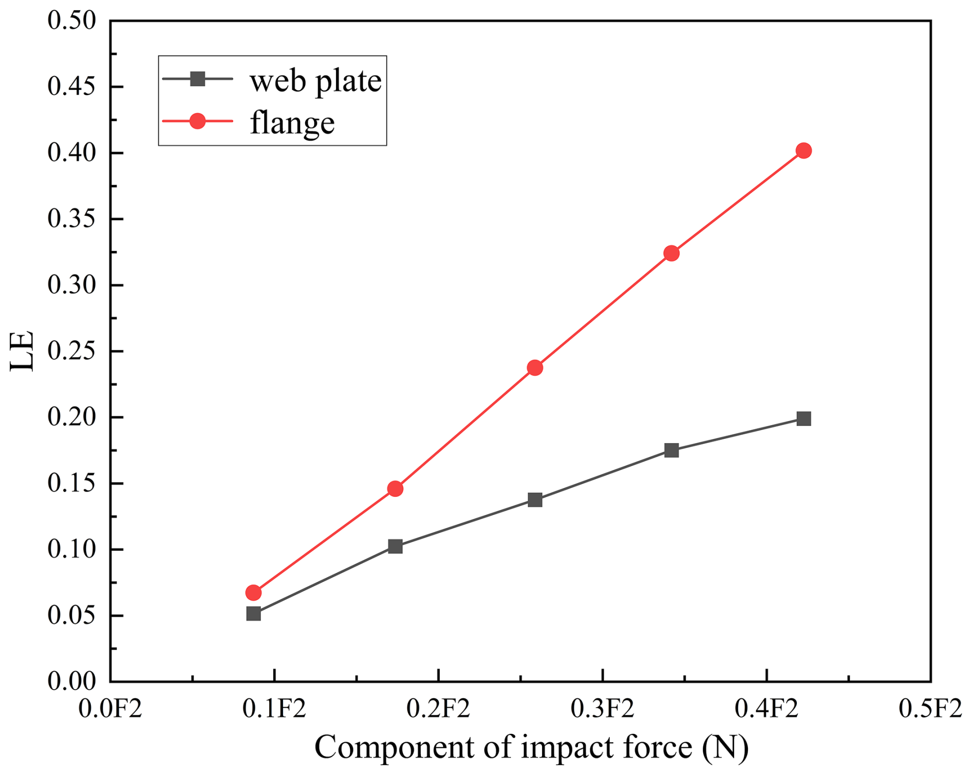
The strain versus impact component force of the web plate and flange in the impact area were obtained from the curve, as illustrated in Fig. 22. A larger impact angle resulted in a greater impact force, which increased the in-plane load within the flange and led to plastic buckling. Conversely, the smaller impact force component F1 resulted in a reduced in-plane load within the web plate. As shown in Fig. 22, the strain variations of the web plate gradually stabilized with increasing impact angle, whereas the plastic strengthening effect of the lower flange strain was not evident, exhibiting a linear increasing trend. Therefore, it can be concluded that as the impact angle increased, the flange lost stability while the web plate remained relatively stable.
3.3.3 Dynamic responses of pallet fence with different impact angles
The dynamic responses of the fence varied with changes in the impact angle. In this section, the middle part and root part of the fence were selected and the pallet initial impact angles were 5, 10, 15, 20 and 25°, respectively.
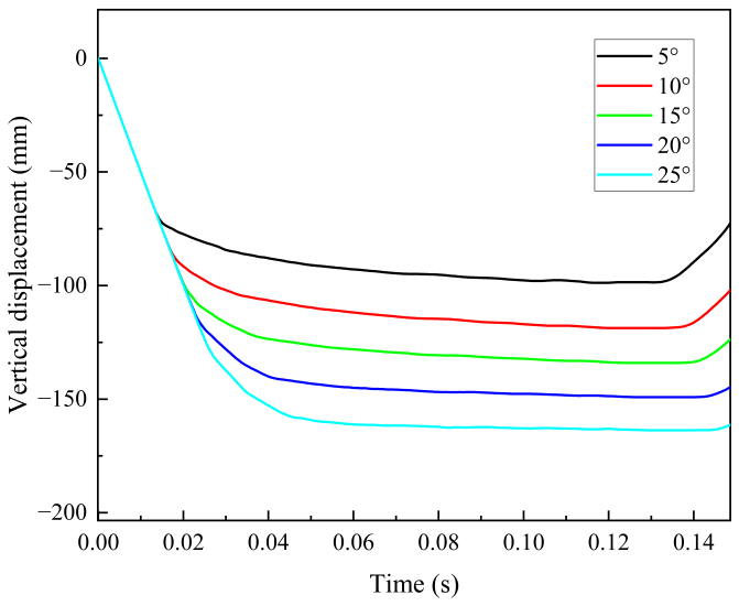
Figure 23Response curve of vertical displacement versus time for the fence with different impact angles.
Based on the vertical displacement of the pallet fence, the impact occurred between approximately 0.04 and 0.14 s, with a duration of approximately 0.1 s, as illustrated in Fig. 23. Therefore, the displacement of the pallet fence was selected for observation during this period. Meanwhile, displacement U2 was selected as the reference for fence deformation to account for and mitigate against potential interference caused by the overall movement of the pallet fence following impact.
As illustrated in Fig. 24, the root part exhibited greater displacement compared to the middle part of the fence when the pallet underwent a fall at slanted initial states. The collision occurred when the impact area came into contact with the ground, and then the stress wave propagated to the entire base and fence in an extremely short period of time.
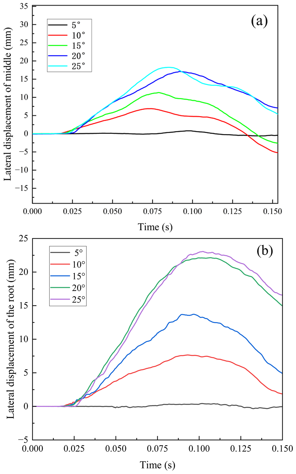
Figure 24Response curves of fence lateral displacement versus time under different impact angles: (a) the root part of fence; (b) the middle part of fence.
The impact component force versus lateral displacement for the vertical rod was obtained, as shown in Fig. 25. When the pallet fell at inclined initial angles, the fence was not only elastically constrained by the submarine cables due to impact forces but also by additional boundary conditions. Therefore, the fence was more susceptible to destabilization compared to a horizontal fall. As illustrated in Fig. 25, it was evident that when the radial force component reached 0.259F at an impact angle of 15°, the displacements of both the root and mid-part of the fence experienced a sudden change, leading to plastic buckling.
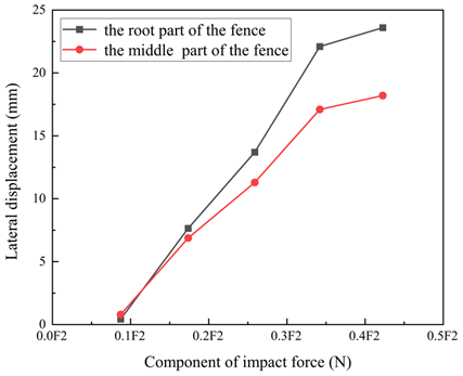
Figure 25Impact component force versus lateral displacement of the pallet fence with different impact angles.
- 1.
As the mass of the submarine cable increased, the proportion of kinetic energy converted into strain energy within the pallet gradually decreased. According to the empirical formula, the energy absorption capacity of the submarine cable increased linearly with the applied mass. Consequently, the displacement of the pallet web plate initially increased and subsequently decreased, while the deflection of the fence progressively increased.
- 2.
At the horizontal initial state, the pallet base and fence primarily underwent elastic deformation upon impact. At slanted initial states, the pallet base and fence in the impact area primarily underwent plastic deformation upon impact.
- 3.
When the pallet fell with a horizontal initial state, the base and fence exhibited a tendency toward instability. Elastic buckling of the base web plate occurred when the falling velocity exceeded 5 m s−1, and elastic-plastic buckling of the fence occurred when the velocity exceeded 8 m s−1.
- 4.
At a slanted initial state, the web plate exhibited a tendency toward stability, while the flange within the impact area demonstrated a propensity for instability, indicating that the in-plane load was a critical factor influencing the structural stability of the pallet. Compared with falling at a horizontal initial state, it was more likely to cause elastic-plastic buckling of the fence at slanted initial states, and the buckling occurred at an impact angle of 15°.
The present study did not involve the development of any custom software code. All numerical simulations were carried out using the commercial finite element software ABAQUS/Explicit. No user-defined subroutines (e.g., VUMAT or other custom implementations) were employed in this study. The source code of ABAQUS is proprietary and not publicly accessible due to licensing restrictions. Therefore, no standalone software code is available for public release. The numerical procedures, material models, boundary conditions, and analysis parameters are described in sufficient detail in the paper to ensure reproducibility of the results.
The data supporting the findings of this study are not publicly available due to confidentiality and institutional restrictions. The data are associated with ongoing research projects and therefore cannot be publicly released. However, the data may be made available from the corresponding author upon reasonable request and with permission from the relevant parties.
Conceptualization: YD and YL. Methodology: YW and CZ. Software: YW. Validation: HZ and CL. Formal analysis: LZ and YL. Investigation: HZ. Resources: HZ and CL. Data curation: HY and ZQ. Writing (original draft preparation): YW. Writing (review and editing): CZ, LZ and PP. Visualization: CL and ZQ. Supervision: YL. Project administration: HZ. Funding acquisition: YD. All authors have read and agreed to the published version of the paper.
The contact author has declared that none of the authors has any competing interests.
Publisher's note: Copernicus Publications remains neutral with regard to jurisdictional claims made in the text, published maps, institutional affiliations, or any other geographical representation in this paper. The authors bear the ultimate responsibility for providing appropriate place names. Views expressed in the text are those of the authors and do not necessarily reflect the views of the publisher.
The authors gratefully acknowledge the financial support provided by the Graduate Research and Innovation Projects of Jiangsu Province under grant no. SJCX24_2090.
This research has been supported by the Graduate Research and Innovation Projects of Jiangsu Province (grant no. SJCX24_2090).
This paper was edited by Liangliang Cheng and reviewed by three anonymous referees.
Amini, Y., Heshmati, M., and Daneshmand, F.: Dynamic behavior of conveying-fluid pipes with variable wall thickness through circumferential and axial directions, Mar. Struct., 72, 102758, https://doi.org/10.1016/j.marstruc.2020.102758, 2020.
Chae, K., Nam, W., and Shim, C.: Influence of coiling behavior on axial stress in steel wires of submarine power cables: A numerical study, Ocean Eng., 288, 116014, https://doi.org/10.1016/j.oceaneng.2023.116014, 2023.
Chang, H.-C. and Chen, B.-F.: Mechanical behavior of submarine cable under coupled tension, torsion and compressive loads, Ocean Eng., 189, 106272, https://doi.org/10.1016/j.oceaneng.2019.106272, 2019.
Cheng, Y., Liu, K., Li, Y., Wang, Z., and Wang, J.: Experimental and numerical simulation of dynamic responses of U-type corrugated sandwich panels under low-velocity impact, Ocean Eng., 245, 110492, https://doi.org/10.1016/j.oceaneng.2021.110492, 2022.
Clifton, R. J.: Stress wave experiments in plasticity, Int. J. Plasticity, 1, 289–302, https://doi.org/10.1016/0749-6419(85)90016-6, 1985.
Gupta, S., Matos, H., LeBlanc, J. M., and Shukla, A.: Shock initiated instabilities in underwater cylindrical structures, J. Mech. Phys. Solids, 95, 188–212, https://doi.org/10.1016/j.jmps.2016.05.034, 2016.
Huang, B., Chen, P., Yang, Z., Zhou, J., Ren, Q., and Zhu, B.: Experimental study of dynamic responses of the box-girder coastal bridge under the regular wave actions with considering the wave-structure coupling, Appl. Ocean Res., 150, 104112, https://doi.org/10.1016/j.apor.2024.104112, 2024.
Kong, X., Zhou, H., Zheng, C., Pei, Z., Yuan, T., and Wu, W.: Research on the dynamic buckling of a typical deck grillage structure subjected to in-plane impact load, Mar. Struct., 78, 103003, https://doi.org/10.1016/j.marstruc.2021.103003, 2021.
McNamara, J. F. and Harte, A. M.: Three-Dimensional Analytical Simulation of Flexible Pipe Wall Structure, J. Offshore Mech. Arct., 114, 69–75, https://doi.org/10.1115/1.2919961, 1992.
Nie, B. and Zhang, H.: Hoop and axial plastic buckling modes of submerged cylindrical shells subjected to side-on underwater explosion shock wave, Mar. Struct., 84, 103200, https://doi.org/10.1016/j.marstruc.2022.103200, 2022.
Polizzotto, C.: Strain gradient plasticity, strengthening effects and plastic limit analysis, Int. J. Solids Struct., 47, 100–112, https://doi.org/10.1016/j.ijsolstr.2009.09.019, 2010.
Rostamijavanani, A.: Dynamic Buckling of Cylindrical Composite Panels Under Axial Compressions and Lateral External Pressures, Journal of Failure Analysis and Prevention, 21, 97–106, https://doi.org/10.1007/s11668-020-01032-3, 2020.
Shi, G.-J., Xiong, Y-f., and Wang, D.: Dynamic buckling experiments for stiffened panels under falling hammer impact, Structures, 57, 105117, https://doi.org/10.1016/j.istruc.2023.105117, 2023.
Volmir, A. S.: Nonlinear dynamics of plates and shells, Moscow Science, FTD-HC-23-851-74, 432 pp., 1972.
Xie, H., Liu, F., Tang, H., and Liu, X.: Numerical study on the dynamic responses of a truncated ship-hull structure under asymmetrical slamming, Mar. Struct., 72, 102767, https://doi.org/10.1016/j.marstruc.2020.102767, 2020.
Xin, Z. and Han, Z.: Energy Method on Dynamic Buckling of Cylindrical Shell with Simply-Fixed Supported subjected to Axial Impact of Rigid Mass, J. Phys. Conf. Ser., 1676, 012168, https://doi.org/10.1088/1742-6596/1676/1/012168, 2020.
Xiong, Y., Shi, G., Wang, F., and Wang, D.: Dynamic buckling analysis of stiffened panels under in-plane uniaxial impact considering plate/web interaction, Ocean Eng., 279, 114462, https://doi.org/10.1016/j.oceaneng.2023.114462, 2023.
Yan, Z., Cai, H., and Xing, X.: Dynamic buckling analysis of hull structure under in-plane impact load, International Joint Conference on Civil and Marine Engineering, 31, 300–306, 2023.
Yang, B. and Wang, D.: Dynamic buckling of stiffened plates with elastically restrained edges under in-plane impact loading, Thin Wall. Struct., 107, 427–442, https://doi.org/10.1016/j.tws.2016.06.019, 2016.
Yang, B. and Wang, D.: Numerical study on the dynamic responses of the large containership's bow structure under slamming pressures, Mar. Struct., 61, 524–539, https://doi.org/10.1016/j.marstruc.2018.06.010, 2018.
Yang, B. and Wang, D. Y.: Buckling Strength of Rectangular Plates with Elastically Restrained Edges Subjected to In-plane Impact Loading, in: Safety of Sea Transportation, CRC Press, 233–240, https://doi.org/10.1201/9781315099088-39, 2017.
Yang, J., Sun, Z., and Liang, S.: A Numerical Study on the Water Impact of the Rigid/Elastic Box-Like Structure, China Ocean Eng., 37, 333–342, https://doi.org/10.1007/s13344-023-0027-1, 2023.
Zhang, S.: Buckling and Ultimate Strength Assessments of Ship Structures, Vol. 2B: Structures, Safety and Reliability, ASME 2013 32nd International Conference on Ocean, Offshore and Arctic Engineering, ASME, V02BT02A026, https://doi.org/10.1115/omae2013-11137, 2013.
Zhou, J., Pei, Z., Wu, W., and Ding, J.: Progressive Collapse Behavior of Ship Structures Considering Fluid-Structure Interaction Effect, Vol. 2: Structures, Safety, and Reliability, ASME 2023 42nd International Conference on Ocean, Offshore and Arctic Engineering, ASME, V002T02A058, https://doi.org/10.1115/omae2023-102755, 2023.
Zhu, H., He, J., Yao, D., Yang, W., Wang, Y., and Hong, J.: Dynamic responses of cylindrical shell supporting structure under multiple impacts: experimental and numerical investigation, J. Braz. Soc. Mech. Sci., 46, 417, https://doi.org/10.1007/s40430-024-04894-y, 2024.