the Creative Commons Attribution 4.0 License.
the Creative Commons Attribution 4.0 License.
 | 18 Sep 2026
Shaft-flexibility-induced hydrodynamic support redistribution and modal response in a multi-support bearing-rotor system
Yulin Zhang
Bing Li

Wubin Xu
Hanyu Guo
Yanpeng Yuan
Shaft flexibility in a multi-support bearing-rotor system simultaneously alters the journal attitudes at multiple supports, thereby redistributing the hydrodynamic support conditions along the shaft. This study investigates this system-level transmission in a three-disk, four-support bearing-rotor system subjected to end loading. The eccentricity and inclination states of all four journals are determined simultaneously through a coupled equilibrium solution of a Timoshenko beam structural model and a finite-length Reynolds lubrication model, and the resulting load- and speed-dependent oil-film coefficients are introduced into a finite-element rotordynamic model. End loading produces a strongly nonuniform support response: at 3000 rpm, the stiffness and damping traces of the loaded-end support J4 increase by 4298.0 % and 293.6 %, respectively, and at 2884 rpm its direct-stiffness trace reaches approximately 47 times the initial value. Continuous modal-branch tracking shows, however, that the neighboring low-order FW and BW synchronous branches change by only −0.00037 % and +0.00039 %, whereas the higher-order H1 and H2 branches change by +0.0140 % and +0.1477 %, respectively. The contrast is explained by the markedly different generalized participation of the bearing locations in the corresponding modal branches. These results show that the global dynamic consequence of local oil-film strengthening is governed by hydrodynamic support redistribution and modal participation at the support locations rather than by the magnitude of the local bearing-stiffness change alone.
- Article
(10879 KB) - Full-text XML
-
Supplement
(845 KB) - BibTeX
- EndNote


Hydrodynamic journal bearings at multiple support positions are ubiquitously employed in flexible shaft systems of rotating machinery, including engine camshafts and compressors. In camshaft systems of high-power construction machinery engines, shaft flexibility combined with asymmetric transmission loads may induce journal center displacement and angular misalignment on a scale comparable to the bearing clearance and oil-film thickness. Under such conditions, a local end load does not exclusively influence the bearing at the loaded end. Instead, the resultant shaft deformation propagates along the shared flexible shaft, simultaneously altering the journal attitudes and hydrodynamic characteristics of multiple supports. A thorough understanding of this spatial transmission mechanism is therefore critical to identifying the effective dynamic boundaries of flexible multi-support bearing-rotor systems.
The influence of shaft-deformation-induced journal misalignment on bearing lubrication performance has been extensively documented for both steady-state and dynamically loaded operating conditions. Sun and Gui (2004) formulated a hydrodynamic lubrication model for journal bearings subject to shaft-deformation-induced misalignment, and Sun et al. (2005) experimentally confirmed that load-induced misalignment substantially modifies bearing lubrication states. Subsequent investigations have further demonstrated that journal inclination distorts the convergent wedge geometry, reshapes pressure distribution, reduces minimum film thickness, and modifies bearing dynamic coefficients (Feng et al., 2019; Jang and Khonsari, 2019; Gu et al., 2020; Xie et al., 2021; Liu et al., 2022). Collectively, these studies have established that journal inclination should be treated as an evolving hydrodynamic boundary variable rather than a fixed assembly error. Nevertheless, the primary scope of these works remains confined to the local lubrication response of individual misaligned bearings.
Recent research efforts have extended misalignment analysis to incorporate fluid–structure interaction effects and rotor system dynamics. Partitioned coupling strategies have been applied to solve dynamically loaded bearing problems (Profito et al., 2019), while distributed bearing models have been adopted to investigate shaft bending and deformation-dependent bearing coefficients (Ouyang et al., 2022; He et al., 2022). Dynamic misalignment models have also highlighted the critical role of time-varying journal attitudes in governing lubrication response and rotordynamic behavior (Xiong et al., 2024; Sun et al., 2024a, b; Xie et al., 2024). Despite these advances, most existing studies either focus on a single bearing or evaluate local journal attitudes that are prescribed a priori or determined predominantly from local deformation states. In multi-support systems, journal attitudes at individual bearings are not independent quantities: deformation of the common shaft and hydrodynamic reaction forces generated at all supports collectively govern the global system equilibrium. Accordingly, strengthening of the oil-film constraint at one support may be accompanied by weakened constraints, marginal changes, or load redistribution at the remaining supports. The mechanisms by which local external loads propagate via shaft flexibility to redistribute hydrodynamic support constraints across multiple bearings, and how such redistributed boundaries subsequently affect different rotor modal branches, remain insufficiently elucidated.
To address the aforementioned system-level coupling issues that have not yet been fully resolved, this work investigates a three-disk, four-support bearing-rotor system subjected to end loads, with particular attention to how shaft flexibility redistributes hydrodynamic support conditions along the shaft. Unlike conventional studies that individually preset the journal misalignment state at each bearing, the present work simultaneously solves the eccentricity and inclination of all four journals through coupled shaft–oil-film equilibrium. This approach directly captures the physical process by which local loads are transmitted through the shared flexible shaft and redistributed across multiple supports. Building on this, complete oil-film stiffness and damping matrices under varying load and speed conditions are derived to characterize the evolution of hydrodynamic support boundaries and to characterize the evolution and increasing axial nonuniformity of the hydrodynamic support distribution. The redistributed support boundary conditions are subsequently embedded into a finite-element rotor dynamics model, and continuous tracking of synchronous modal branches is carried out. In this way, the sensitivity of critical speeds and modal responses across different branches is linked to the generalized participation degree at each support position. A flexible-deformation index Mr is also introduced to enable compact quantitative representation of the combined eccentricity and inclination state. In summary, the present work establishes a coherent physical connection among shaft deformation, journal attitude redistribution, hydrodynamic support redistribution, and dynamic responses of modal branches. This extends the scope of traditional misaligned bearing research from local lubrication performance analysis to the evolutionary mechanism of dynamic boundaries in multi-support systems.
2.1 Physical system and modeling assumptions
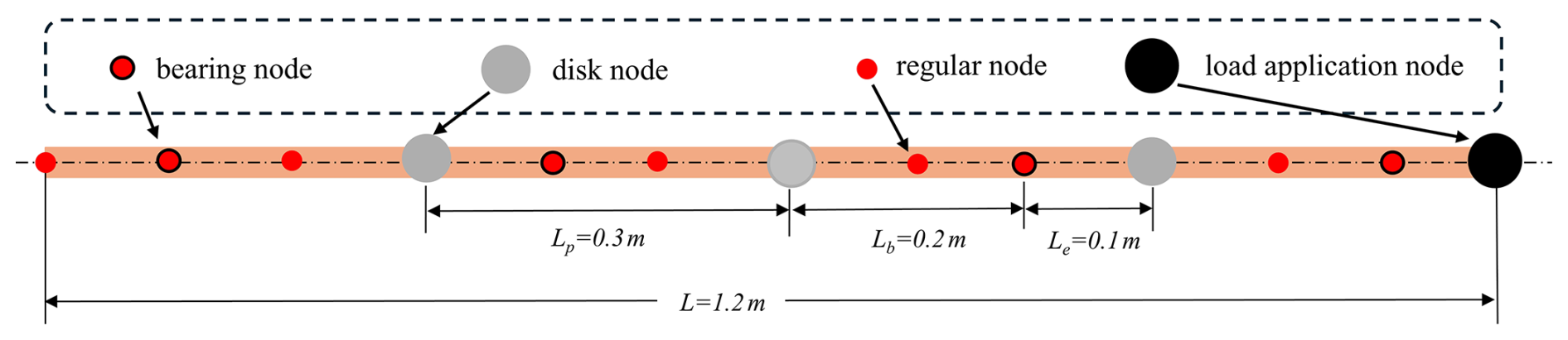
The three-disk, four-support bearing-rotor system shown in Fig. 1 represents a flexible camshaft-type multi-support journal-bearing-rotor system subjected to asymmetric loading. Shaft flexibility transmits the end load among the supports, producing nonuniform journal eccentricity and inclination and consequently altering the local oil-film thickness, pressure distribution, and dynamic coefficients. An equivalent end load is introduced to retain the essential mechanism of support-reaction redistribution while avoiding unnecessary geometric complexity. The structural and hydrodynamic fields are coupled through the journal attitudes and bearing reaction forces at all four supports. For a prescribed end load and rotational speed, deformation of the common shaft simultaneously changes the journal-center displacement and inclination at each bearing, while the resulting oil-film reaction forces are fed back into the global structural equilibrium. Consequently, the four bearing operating states are determined as mutually coupled equilibrium quantities rather than as independently prescribed misalignment conditions. The converged support-specific states are subsequently used to determine the oil-film dynamic coefficients, thereby defining the deformation-dependent support conditions used in the global rotordynamic model.
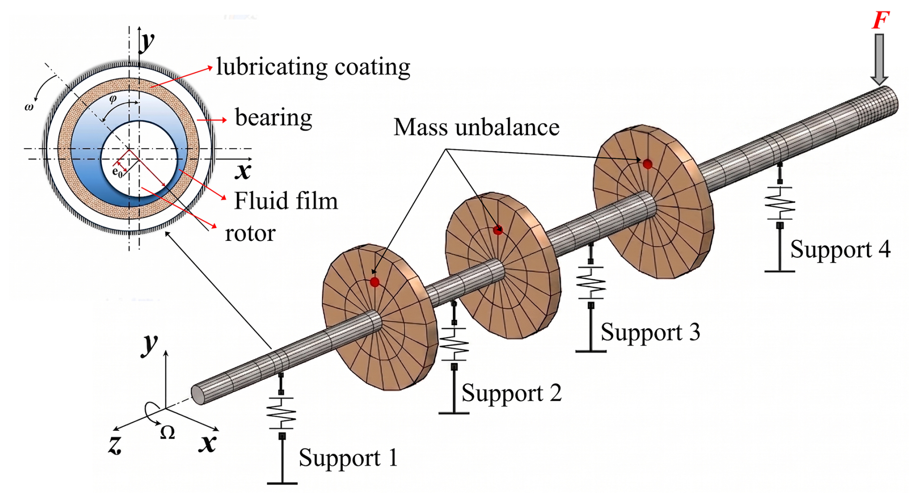
The rotor shaft is formulated using a small-strain, small-rotation Timoshenko beam model whose structural stiffness matrix is constructed in the reference configuration. Thus, second-order axial elongation caused by transverse bending and the associated configuration-dependent geometric stiffness are not included in the baseline structural model. This assumption applies only to the structural kinematics: journal eccentricity and centerline inclination are retained explicitly in the lubrication geometry, and the oil-film pressure, reaction forces, and dynamic coefficients are updated with the converged FSI state. The subsequent modal analysis is therefore a small-perturbation analysis about each state-dependent hydrodynamic equilibrium. An a posteriori kinematic check at the four bearing sections and a deliberately conservative stress-stiffening sensitivity estimate confirm that geometric nonlinearity produces only small corrections within the investigated operating range; a detailed assessment is provided in the Supplement.
The lubricant is modeled as incompressible, isoviscous, and laminar, and the analysis is restricted to converged hydrodynamic equilibria and small perturbations about those equilibria (Zhang et al., 2019). Inlet-pressure effects are neglected because the supply pressure is small relative to the hydrodynamic film pressure in the investigated range (Feng et al., 2019). Thermal transport, asperity contact, and mass-conserving cavitation are not solved explicitly; a half-Sommerfeld treatment is used for the divergent region. The first-order velocity-dependent squeeze contribution is retained in the linearized damping coefficients, whereas finite-amplitude transient squeeze, moving cavitation/reformation boundaries, and mixed-lubrication contact are outside the present formulation. Supplementary sensitivity checks show that the laminar assumption is well satisfied and that reasonable viscosity variations do not change the support-redistribution ordering, although the exact pressure peaks, minimum film thickness, and extreme J4 coefficient amplitudes remain model-dependent in the limiting thin-film state.
2.2 Shaft deformation and journal-attitude representation
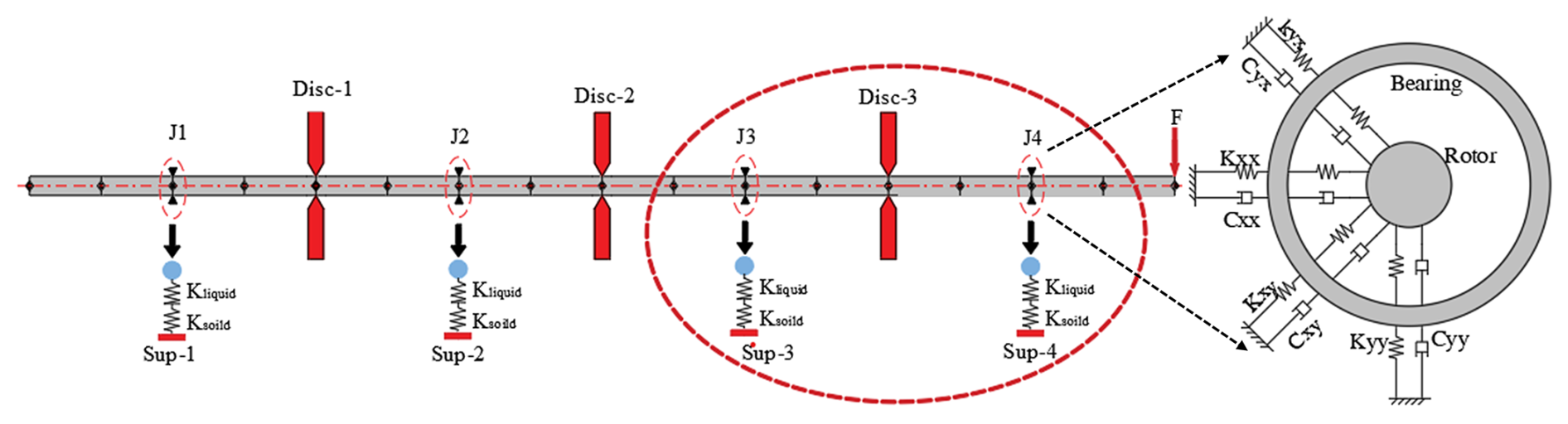
A finite-element formulation is employed to analyze the multi-support rotor–journal bearing system shown in Fig. 2. The shaft is modeled globally using Timoshenko beam theory so that both bending deformation and shear deformation, as well as their influence on the attitude of each supported journal section, can be represented. The global axial coordinate is denoted by z, the transverse x axis is taken as positive to the right, and the vertical y axis is taken as positive downward. In each transverse vibration plane, u (z) and ϕ (z) denote the lateral displacement and cross-sectional rotation, respectively. The fundamental relations of the Timoshenko beam are given in Eq. (1).
Here, Q is the shear force, k is the shear correction factor, G is the shear modulus, A is the cross-sectional area, and M is the bending moment. The shaft is divided axially into two-node beam elements. Each node contains lateral displacement and sectional-rotation degrees of freedom, with two degrees of freedom in each of the x and y planes. The element degree-of-freedom vector is denoted by qe. Based on the principle of virtual work, the element stiffness matrix Ke and consistent mass matrix Ke are derived as shown in Eq. (2):
Here, Le is the assembly matrix from element to global degrees of freedom. The structural static stiffness operator Ks is then obtained, and the static deflection and sectional attitude are solved under the prescribed external loads and bearing oil-film reaction forces. For an axisymmetric shaft made of homogeneous material, the structural equations have the same form in the two transverse planes. The external loads acting on the shaft include self-weight, the end load F, and concentrated forces induced by the disks. The oil-film reaction force at the ith bearing is denoted by Foil,i. The equilibrium point is first obtained by enforcing global balance among structural internal forces, external loads, and oil-film reactions, as expressed by Eq. (3):
In Eq. (3), Ks is the static stiffness operator obtained from the Timoshenko beam discretization, Bi is the mapping matrix from the support force to the structural degrees of freedom, and q is the structural degree-of-freedom vector. By extracting the actual centerline slope at the bearing section, the slope components can be obtained as Eq. (4):
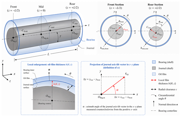
Thus, for the i-th bearing section z=zi, the eccentric displacement of the journal center relative to the bearing center is expressed as [xi,yi]. By normalizing it with respect to the radial clearance C, the dimensionless displacement components and eccentricity ratio are obtained as . The parameters required for the subsequent lubrication characteristic calculation are then extracted using Eq. (5).
where φi is the attitude angle of the journal, describing the direction of the journal-center eccentricity vector in the x–y plane; αi is the inclination azimuth angle, representing the in-plane direction of the journal axis inclination vector; and γi is the inclination angle, used to characterize the degree of inclination of the journal axis relative to the bearing axis. The magnitude of the corresponding slope is tanγi, and under the small-angle assumption, tan γi≈γi. To simultaneously capture the coupling effect between journal eccentricity and inclination, a flexible-deformation index Mr is introduced to quantify the coupled eccentricity–inclination state, as defined in Eq. (6).
In Eq. (6), ϵ is the eccentricity ratio and represents the translational displacement of the journal center, whereas tanγi is the dimensionless inclination term, describing the additional edge displacement caused by journal tilting relative to the radial clearance. The weighting coefficient λ balances the relative contributions of the translational and inclination components. It should be emphasized that Mr is used only as a post-processing index for interpreting the journal attitude and does not enter the oil-film coefficient interpolation or the rotor dynamic equations.
To assess the robustness of the weighting coefficient, a global RMS balancing analysis was performed over the operating database, giving a statistical reference value of λRMS=2.3545; a 1000-sample operating-condition cluster bootstrap yielded a 95 % confidence interval of 2.3486–2.3603. Changing λ from 1.5 to this reference value changes the numerical magnitude of Mr but does not alter the support ordering or the characteristic trend: J1 decreases, J2 remains comparatively stable, J3 is transitional, and the loaded-end support, J4, strengthens markedly with load. The value λ=1.5 is therefore retained to preserve a compact O(1) interpretation scale, while the RMS-derived value is used only as an independent reference for sensitivity. The calibration and fixed-state sensitivity results are provided in the Supplement.
2.3 Hydrodynamic lubrication model
When rotor flexible deformation is considered, as shown in Fig. 3, the oil-film thickness at any point (θ,z) within the bearing clearance can be expressed as the superposition of an eccentricity term and an inclination term. Let the bearing length be Lb. The dimensionless oil-film thickness of the bearing is defined as , as given in Eq. (7).
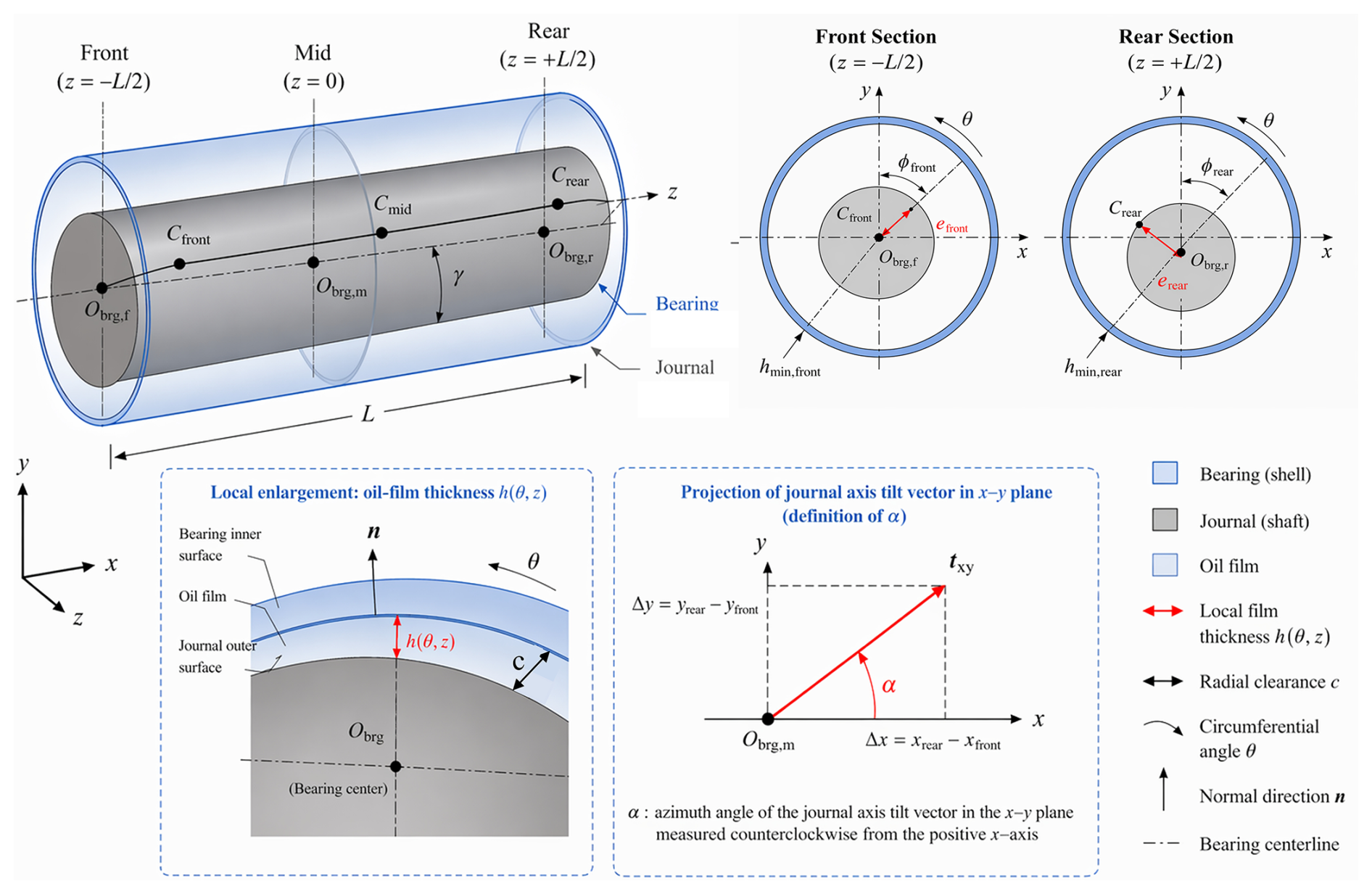
Here, ϵi, φi, αi, and γi are obtained from the structural solution; z* is the dimensionless axial coordinate; and ki is the dimensionless inclination coefficient, which characterizes the contribution of journal inclination to the axial variation in oil-film thickness. The detailed expression is given in Eq. (8).
Under the assumptions of incompressibility, constant viscosity, and laminar flow, the Reynolds equation used in this study is written as Eq. (9):
where R is the journal radius, μ is the lubricant viscosity, and Ω is the journal angular speed.
The half-Sommerfeld condition is implemented by truncating negative pressure in the divergent region. This treatment does not enforce mass conservation in the cavitated zone. During the static FSI equilibrium calculation, . During dynamic-coefficient extraction, however, positive and negative journal-velocity perturbations activate the film-thickness time-derivative term, thereby retaining the first-order squeeze contribution in the linearized damping coefficients. Nonlinear finite-amplitude squeeze, moving cavitation boundaries, and film reformation are not considered. The oil-film reaction force is then obtained by integrating the calculated pressure distribution over the bearing inner surface, as expressed in Eq. (11).
The negative sign indicates that the pressure acting normal to the bearing surface is opposite to the reaction force acting on the journal. Numerical integration is performed using the composite Simpson rule, and (Fx, Fy) from each bearing is supplied to the equilibrium iteration.
2.4 Fluid–structure coupled equilibrium and dynamic coefficient extraction
For the four-support system, the journal operating states cannot be determined independently because all bearing reaction forces act on the same flexible shaft. A change in the reaction force at one support modifies the global shaft configuration and thereby alters the eccentricity and inclination conditions experienced by the remaining supports. The equilibrium problem is therefore formulated at the system level: the shaft deformation determines the journal-center displacement and inclination at all four bearings, while the corresponding oil-film reactions are simultaneously returned to the structural model. Iteration is continued until the structural configuration and the complete set of hydrodynamic support reactions become mutually consistent. This global closure enables the spatial redistribution of journal attitudes and hydrodynamic support conditions to emerge from the coupled solution rather than being imposed through prescribed local misalignment parameters. The rotor system contains four bearings, and the unknown vector of bearing operating points is defined in Eq. (12).
where ξi and ηi are the dimensionless components of the journal-center displacement at the ith bearing section. For a prescribed rotational speed and external load, the bearing forces are calculated from the instantaneous journal attitudes and returned to the global structural equilibrium. The operating-state vector χ in Eq. (12) is therefore updated together with the shaft deformation until the structural and hydrodynamic fields become mutually consistent. The numerical iteration is monitored using the force-equilibrium residual in Eq. (13) at the free structural degrees of freedom.
where the external-load vector contains gravity, disk loads, and the prescribed end load. A damped Newton-type correction is used to update the coupled equilibrium state, with a relaxation factor of 0.4. The normalized equilibrium residual is defined in Eq. (14).
where the subscript f denotes the free structural degrees of freedom. The production calculations use the dimensionless normalized tolerance . The implementation additionally monitors an absolute free-DOF residual threshold of 10−10 N and an auxiliary equilibrium-closure criterion , with a maximum of 200 iterations. Representative convergence data show that the normalized equilibrium and closure criteria are satisfied within 45 iterations for the examined states; detailed residual statistics and the distinction between the diagnostic and internal stopping criteria are provided in the Supplement.
To reduce the computational cost of the subsequent dynamic analysis, an offline database is constructed over N and rpm. For each valid converged hydrodynamic operating point, the equilibrium states of the four bearings are obtained, and the corresponding oil-film stiffness and damping coefficients are extracted by differential perturbation. The index Mr is recorded only to characterize the eccentricity–inclination state and is not used for interpolation. During the state-space analysis, the required bearing coefficient matrices are obtained by bilinear interpolation and assembled separately at J1–J4 into the global finite-element model.
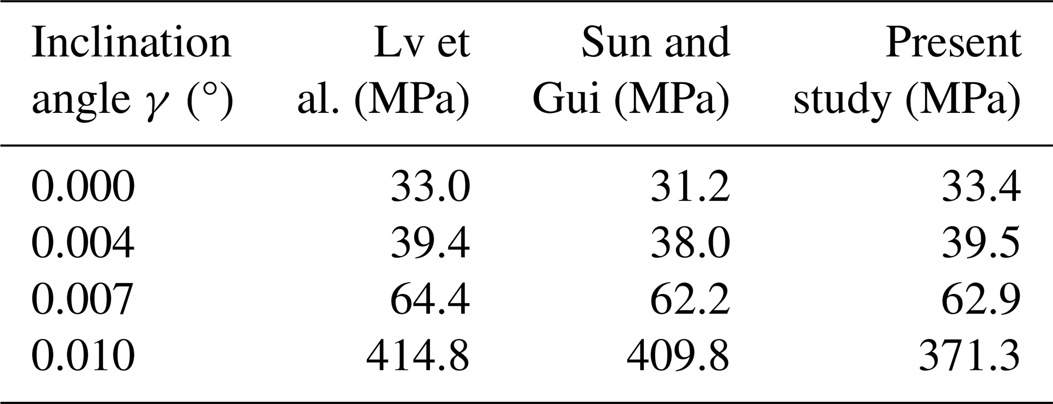
Table 1Comparison of maximum oil-film pressure under journal inclination.
2.5 Database-assisted system dynamic analysis
The converged support-specific dynamic coefficients are subsequently incorporated into the finite-element rotordynamic model shown in Fig. 4. In particular, an equivalent end load is applied at the rightmost node of the model shown in Fig. 4 to represent asymmetric external loading in the camshaft-type system. Let q (t) be the generalized coordinate vector of the system, including lateral displacement and rotational degrees of freedom at each node. Each shaft node in the present model contains four degrees of freedom: two lateral translations and two cross-sectional rotations.
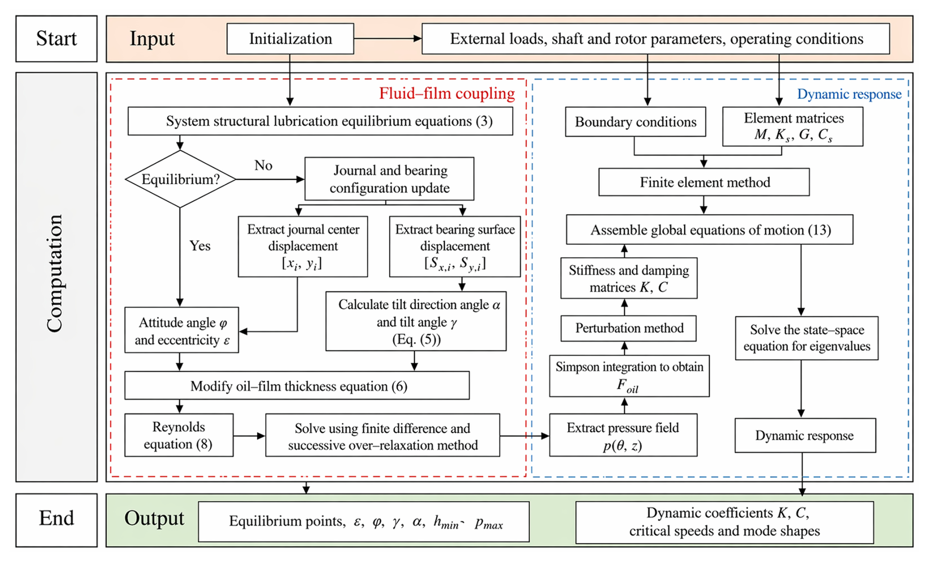
Figure 5Solution procedure for the dynamic response of the bearing-rotor system considering shaft flexibility.
After assembling the shaft, disks, and four bearing supports, the global dynamic equation of the three-disk four-support rotor system is obtained as Eq. (15):
where M is the global mass matrix, Ks is the structural stiffness matrix, G is the gyroscopic matrix, Cs is the structural damping matrix, f (t) is the unbalance excitation force vector, and Koil and Coil are assembled from the oil-film dynamic coefficients obtained from Eq. (16).
The obtained dynamic characteristic coefficients are assembled into the global matrices, as shown in Eq. (17):
The baseline dimensionless displacement and velocity perturbation sizes are both 10−4 and are applied using centered differences. Varying either perturbation from 0.25 to 4 times the baseline changes the stiffness and damping matrices by at most 0.122 % and 0.072 %, respectively, while all coefficient signs are preserved. Reynolds-mesh and perturbation-size sensitivity results are provided in the Supplement.
Because closely spaced complex modes may coexist near a synchronous intersection, modal identity is not determined from frequency proximity alone. For each prescribed end load, the support-specific oil-film stiffness and damping matrices are interpolated from the two-dimensional load-speed database at every trial rotational speed, and the synchronous critical speed of a tracked branch is obtained from the intersection between the branch frequency and the 1X excitation line. Modal continuity between adjacent loading states is evaluated using the mass-weighted complex modal assurance criterion (cMAC):
Starting from the identified low-load synchronous modes, each branch is continued incrementally in F by selecting the candidate with the largest cMAC relative to the preceding state, preventing neighboring synchronous branches from being interpreted as a single branch. To interpret branch-dependent sensitivity, the mass-normalized modal vectors are further used to evaluate generalized bearing-stiffness participation and bearing-location displacement participation. The complete non-symmetric bearing stiffness and damping matrices remain unchanged in the eigenvalue calculation; the participation measures are diagnostic projections only. Their definitions and the finite boundary-substitution decomposition are provided in the Supplement.
2.6 Model validation
The FSI program is validated by comparing the maximum pressure with the values calculated by Sun and Gui (2004) and Lv et al. (2018). The bearing parameters used for comparison are as follows: journal diameter 0.06 m, length-to-diameter ratio 1.1, clearance 30 µm, lubricant viscosity Pa s, and rotational speed 3000 rpm.
The results are listed in Table 1. For inclination angles of 0, 0.004, and 0.007°, the present pressure maxima agree well with Sun and Gui (2004) and Lv et al. (2018), confirming the main pressure-field trend of the misaligned finite-length bearing. At 0.010°, the present value is 371.3 MPa compared with 409.8–414.8 MPa in the references, giving a deviation of approximately 9 %–11 %. This limiting state is characterized by severe local film thinning, for which the pressure peak becomes increasingly sensitive to grid resolution, viscosity, cavitation treatment, and the possible onset of mixed lubrication. Because the present model uses an isothermal constant-viscosity formulation with a non-mass-conserving half-Sommerfeld treatment, the exact extreme pressure peak and associated coefficient amplification should therefore be regarded as model-dependent predictions. The model is used here primarily to resolve the support-redistribution mechanism in the converged hydrodynamic regime; detailed lubrication-regime and equivalent-viscosity sensitivity checks are reported in the Supplement.
The numerical procedure is summarized in Fig. 5. For each sampled end load and speed condition, the shaft deformation and oil-film pressure field are iterated to a mutually consistent FSI state, after which the support-specific dynamic coefficients are extracted and stored. During online dynamic analysis, the required matrices are obtained by bilinear interpolation and assembled at J1–J4. Of the 211 001 sampled load-speed states, 200 304 return valid direct FSI solutions (94.93 %). Only these directly converged states are used in the physical statistics and independent validation. Missing coefficient entries are filled solely to maintain database lookup continuity and are not interpreted as directly converged operating states.
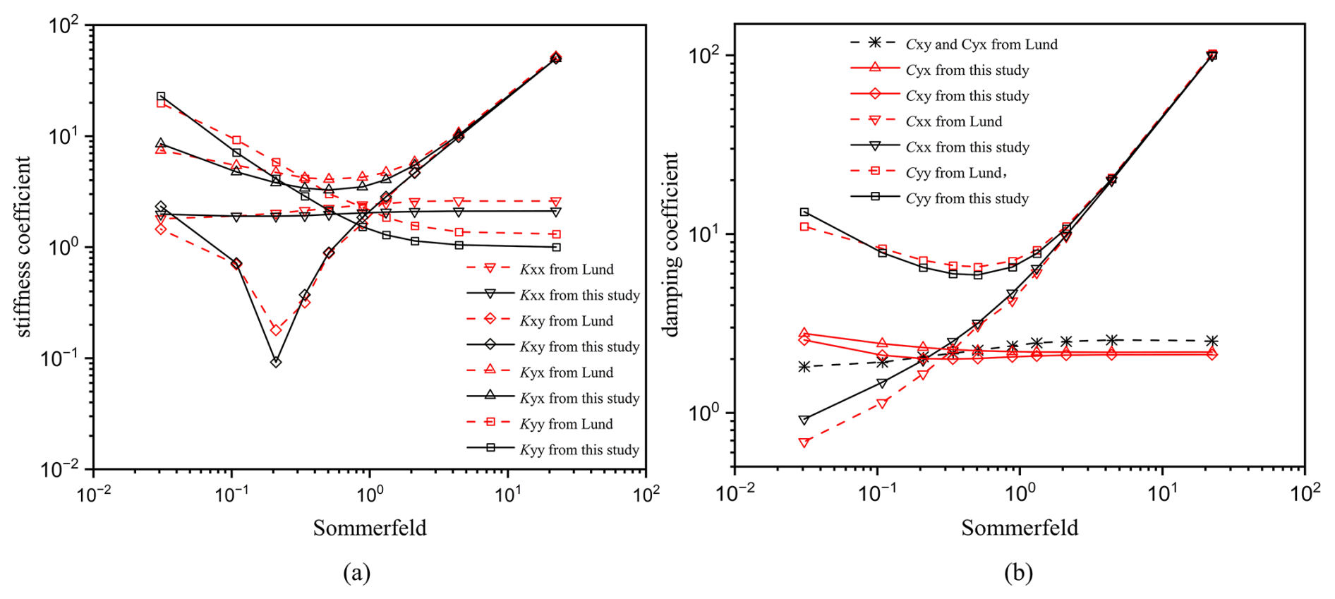
Figure 6 compares the present results with Lund and Orcutt's (1967) results for the non-dimensional stiffness and damping coefficients of a journal bearing with a length-to-diameter ratio of 1. The comparison shows good agreement, indicating that the method used in this study is suitable for the subsequent dynamic analysis.
To validate the flexible rotor model and the modal solution procedure, the mode shapes obtained using the MATLAB model were compared with those predicted by an ANSYS three-dimensional finite-element model under the operating condition of 3000 rpm and F=0 N. As shown in Fig. 7, the normalized bending mode shapes near 53 and 89 Hz obtained using the two models exhibit good overall agreement. The nodal positions near the supports and the deformation peaks at the disk locations are consistently reproduced, with only minor local differences in amplitude. The agreement supports the structural discretization and modal-solution implementation of the MATLAB model. Together with the lubrication and dynamic-coefficient validations above, it provides an independent structural reference for the subsequent modal-branch analysis.
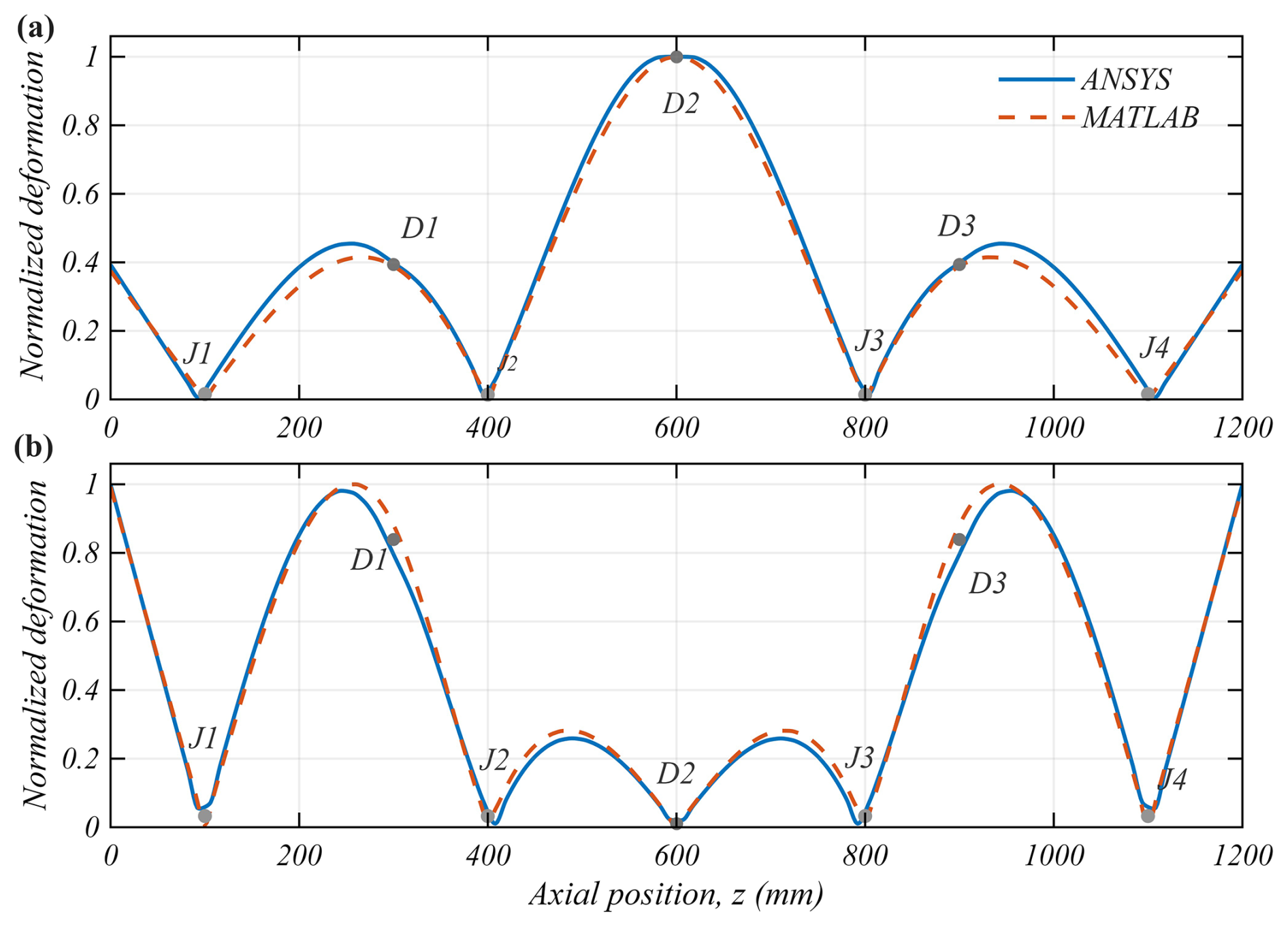
Figure 7Comparison of the normalized bending mode shapes obtained using the MATLAB and ANSYS models: (a) mode near 53 Hz; (b) mode near 89 Hz.
Furthermore, an a posteriori validity check is conducted for the small-deformation assumption of the structure. Among the four bearing sections over all directly converged database states, the maximum recovered centerline inclination is 0.08869°, which corresponds to a second-order geometric elongation term of 0.5 tan2 γ = 1.20 × 10⁻⁶. For further verification, to deliberately amplify the possible stress-stiffening effect, a conservative sensitivity case is constructed by assuming that the maximum local second-order elongation acts uniformly along the full shaft and is fully restrained axially. The relative variations in critical speed for the four synchronous branches, i.e., FW, BW, H1, and H2, are 0.1021 %, 0.1000 %, 0.0777 %, and 0.0742%, respectively, with all associated cMAC values above 0.999998. These results demonstrate that within the scope of the present study, geometric stress stiffening only imposes limited corrections on the synchronous critical speeds and does not induce substantial reconstruction of the reported modes.
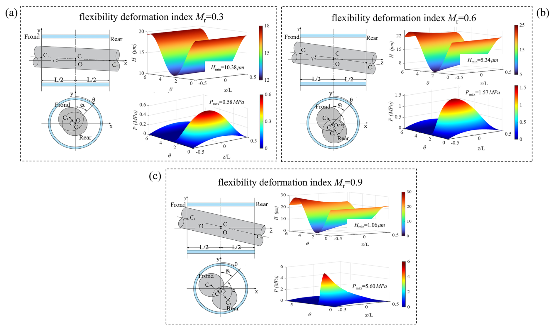
Figure 9Journal attitude, oil-film thickness, and pressure distribution under different flexible-deformation indices Mr: (a) Mr=0.3; (b) Mr=0.6; (c) Mr=0.9.
This section examines how end-load-induced shaft deformation is transmitted through the four hydrodynamic supports. The analysis first identifies the nonuniform evolution of the journal attitudes and local lubrication states, then quantifies the resulting redistribution of support stiffness and damping, and finally evaluates how this redistributed boundary affects continuously tracked synchronous modal branches.
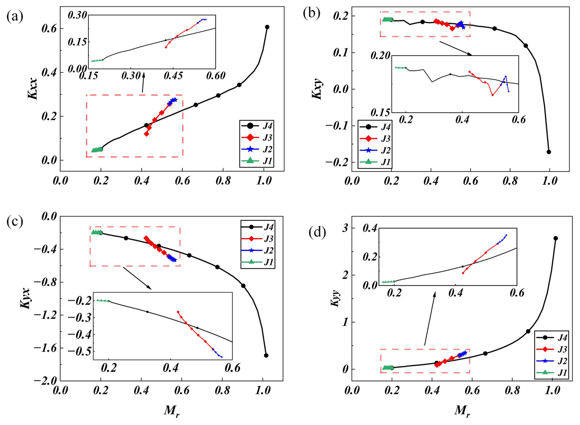
Figure 10Evolution of non-dimensional stiffness coefficients with the flexible-deformation index Mr.
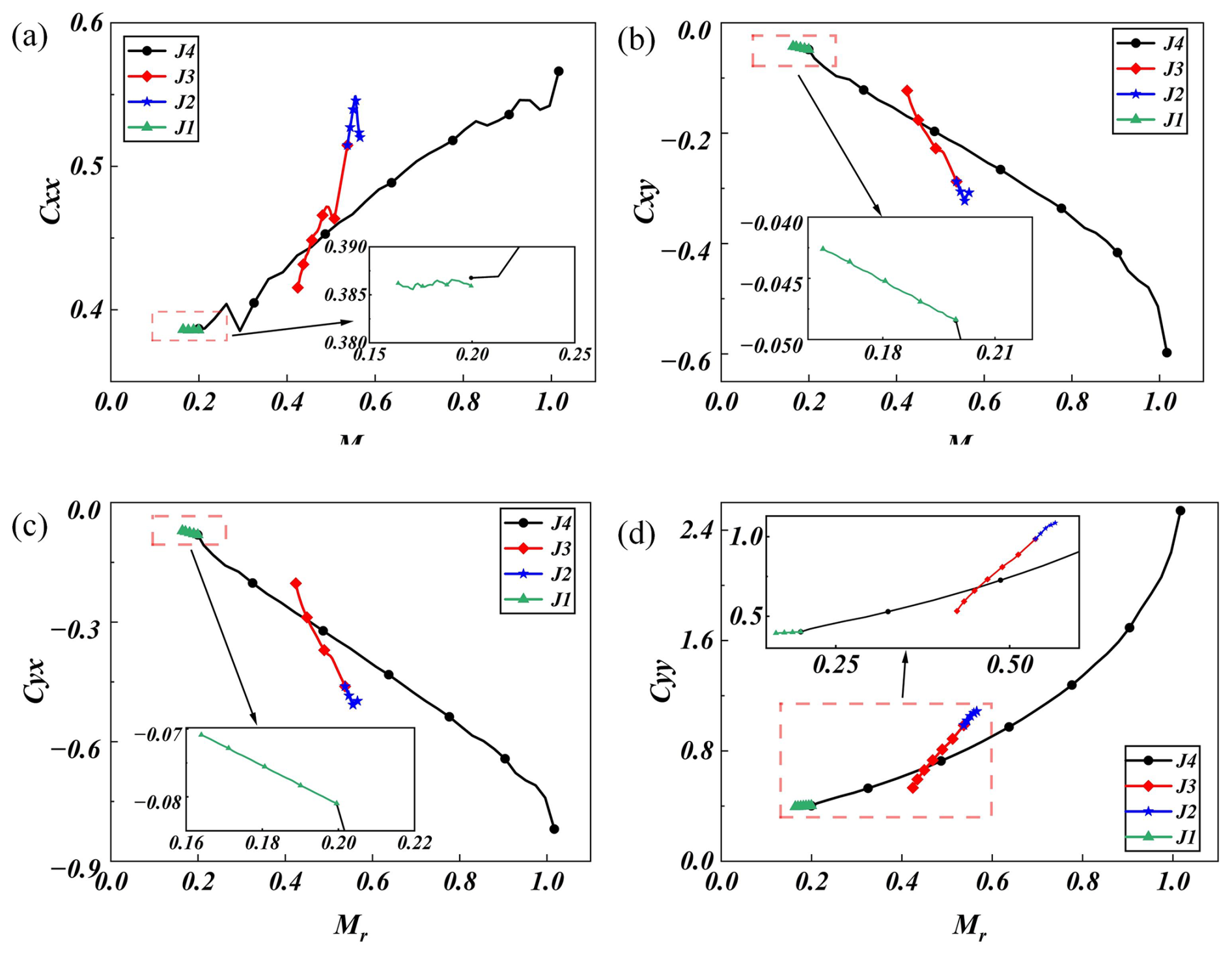
Figure 11Evolution of non-dimensional damping coefficients with the flexible-deformation index Mr.
3.1 Hydrodynamic support redistribution under shaft flexibility
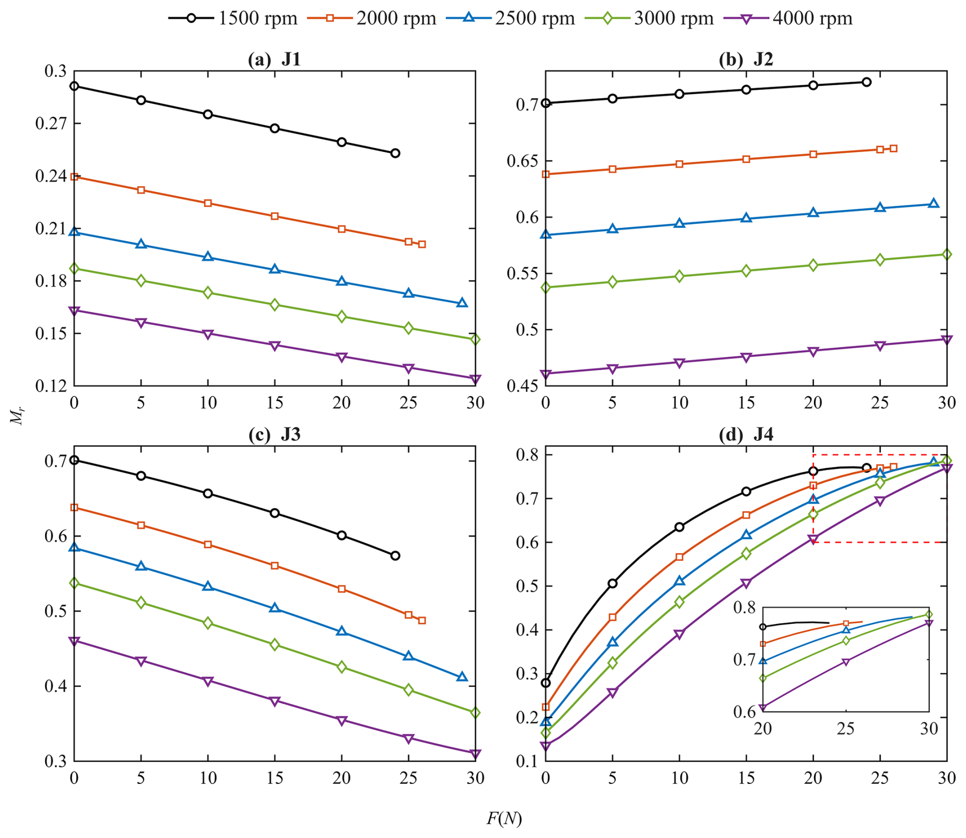
Figure 8 presents the variation in the flexible-deformation index Mr at the four supports under combined load and speed conditions. At F = 0, the nearly coincident values of and indicate an approximately symmetric initial journal-attitude state. End loading rapidly breaks this symmetry: within 0–25 N, Mr at J4 increases by 266.5 %–402.2 %, whereas J1 and J3 decrease, and J2 changes only slightly. At 25 N, the Mr ratios and reach 4.19–6.02 and 1.76–2.33, respectively, showing that shaft flexibility concentrates the eccentricity–inclination coupling at the loaded-end support while redistributing the deformation response of the inner supports. Although increasing speed generally suppresses Mr, this effect weakens at J4 under high loads, indicating that loaded-end attitude amplification becomes dominant.
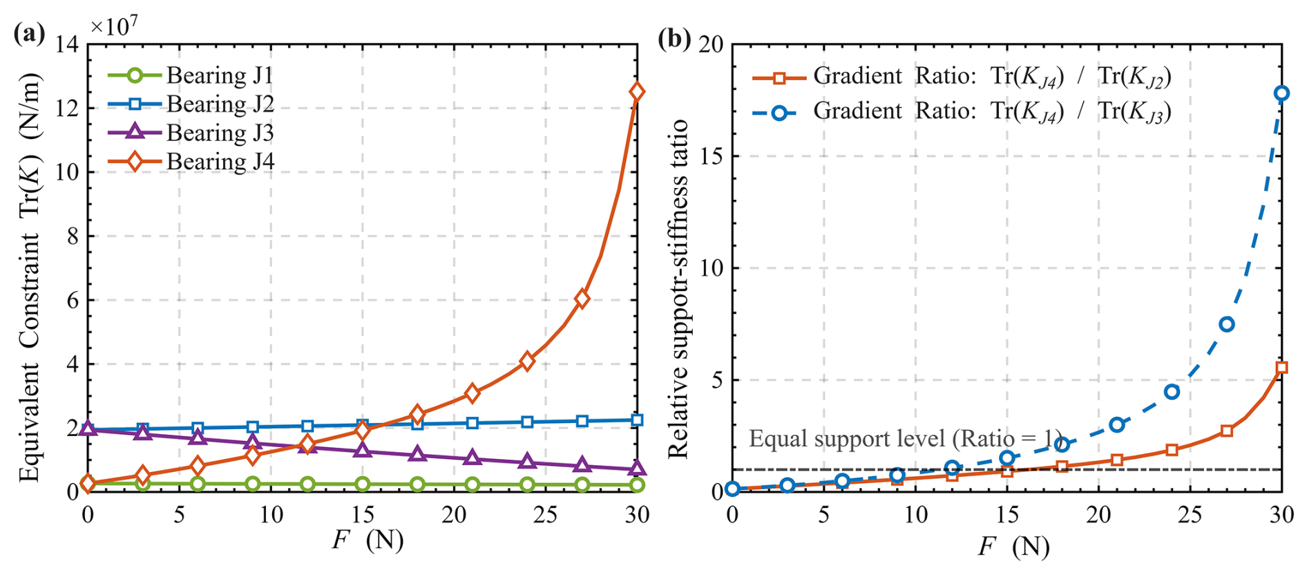
Figure 12Redistribution of the direct-stiffness trace and relative support-stiffness ratios under end loading: (a) Tr (Ki) at J1–J4; (b) Tr (K4) (K2) and Tr (K4) (K3).
Figure 9 shows the evolution of journal attitude, oil-film thickness, and pressure distribution with increasing Mr. At Mr=0.3, the nearly parallel journal produces an approximately axially uniform film and an eccentricity-dominated pressure field. As Mr increases to 0.6 and 0.9, journal inclination introduces pronounced axial asymmetry: Hmin decreases and shifts toward the bearing end, while the pressure field becomes increasingly localized and Pmax increases markedly. These results indicate that Mr effectively characterizes the transition from a primarily eccentric state to an eccentricity–inclination coupled lubrication state under shaft flexibility.
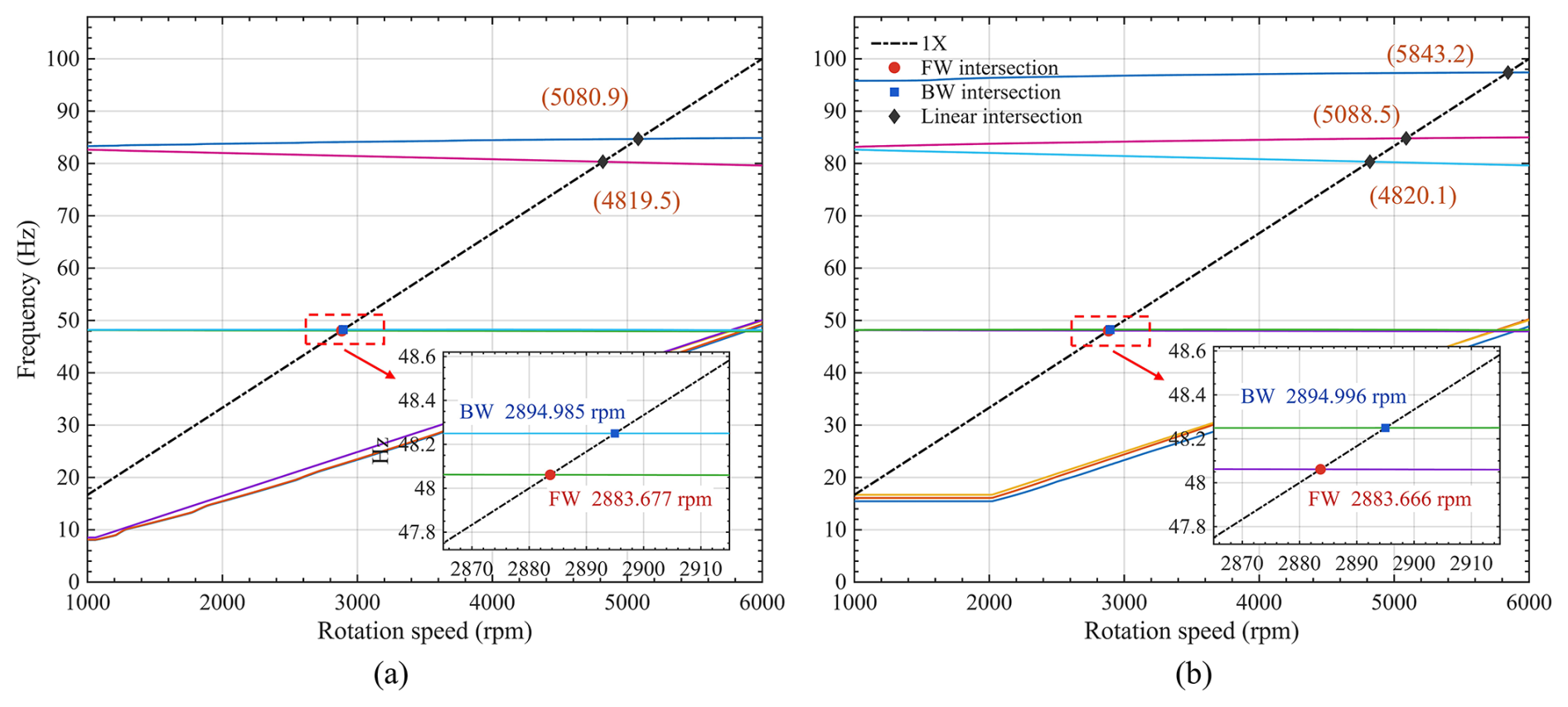
Figure 13Campbell diagrams of the bearing-rotor system under low- and high-flexible-deformation states.
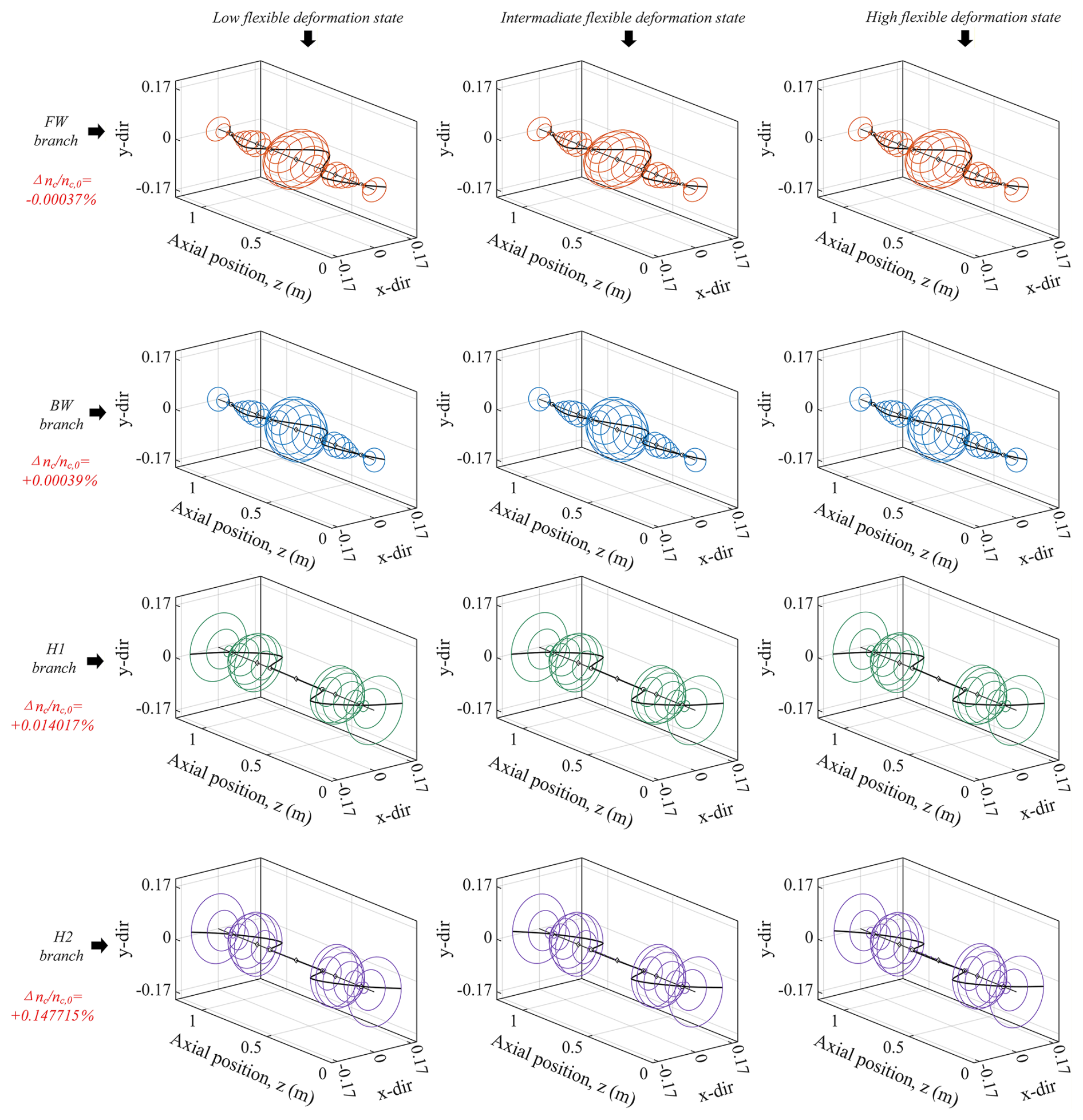
Figure 14Spatial modes of the low- and higher-order synchronous branches under increasing flexible deformation. Rows correspond to the FW, BW, H1, and H2 branches, respectively.
Figures 10 and 11 show that the oil-film dynamic coefficients evolve non-uniformly with Mr at 3000 rpm. The loaded-end support J4 exhibits the strongest amplification: its non-dimensional stiffness trace Tr (K) and damping trace Tr (C) increase by 4298.0 % and 293.6 %, respectively. The cross-coupled terms also become strongly nonlinear, with Kxy reversing sign near Mr=0.96, indicating enhanced pressure-field asymmetry at high inclination levels. In contrast, J3 undergoes marked weakening, with Tr (K) and Tr (C) decreasing by 62.4 % and 36.8 %, while the variations at J1 and J2 remain limited. These results indicate that shaft-flexibility-induced journal inclination locally compresses the converging oil-film wedge at J4 and amplifies its incremental hydrodynamic reaction, whereas the inner supports respond mainly through reaction redistribution. Flexible deformation, therefore, produces a strongly nonuniform redistribution of oil-film stiffness and damping rather than uniform strengthening of all bearings.
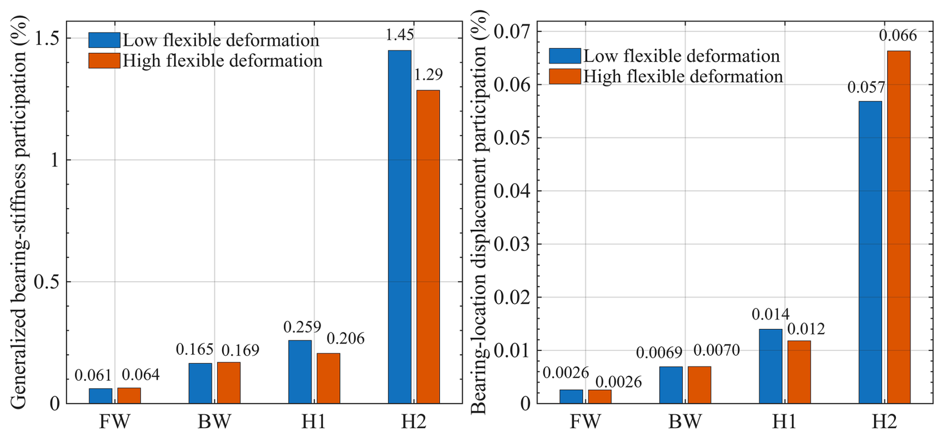
Figure 15Branch-dependent support participation under low- and high-flexible-deformation states.
Figure 12 presents the evolution of the direct-stiffness trace Tr (Ki) and the corresponding relative support-stiffness ratios at 2884 rpm. Tr (Ki) is used only as a scalar descriptor of the direct stiffness level; the complete non-symmetric 2×2 bearing matrices remain in the eigenvalue analysis. With increasing end load, Tr (K4) increases from 2.66×10⁶ to 1.25×10⁸ N m−1, approximately 47.0 times its initial value. By contrast, Tr (K2) increases by only 15.9 %, while Tr (K1) and Tr (K3) decrease by 16.1 % and 63.8 %. The ratios Tr (K4) (K2) and Tr(K4) (K3) increase from 0.137 to 5.56 and 17.82, respectively. Thus, the multi-support boundary evolves from a comparatively shared distribution toward a strongly nonuniform, loaded-end-dominated support-stiffness distribution.
3.2 Branch-dependent modal consequences of hydrodynamic support redistribution
Because Mr is a derived descriptor of the eccentricity–inclination state rather than an interpolation variable of the dynamic-coefficient database, modal identities were tracked continuously with the physical end load F. The continuation analysis identifies two neighboring low-order synchronous branches near 2.89 krpm. The FW branch varies from 2883.6771 rpm at the low-flexible-deformation state to 2883.6665 rpm at the high-flexible-deformation state, whereas the BW branch changes from 2894.9847 to 2894.9960 rpm, corresponding to relative variations of only −0.00037 % and +0.00039 %, respectively. Their minimum adjacent-state cMAC values are 0.999966 and 0.999979, while the maximum inter-branch cMAC is only 0.0885, confirming that they are two distinct neighboring branches. As shown in Fig. 13, the higher-order synchronous branches H1 and H2 exhibit larger critical-speed variations of +0.01402 % and +0.14772 %, respectively, and an additional high-order synchronous intersection appears at 5843.2 rpm in the high-flexible-deformation state. The synchronous critical-speed response is therefore strongly branch-dependent.
To determine whether this branch dependence originates from global mode-shape reconstruction, Fig. 14 compares the spatial modes of the FW, BW, H1, and H2 branches under increasing deformation. The global modal patterns remain highly consistent, whereas the critical-speed sensitivities differ by more than 2 orders of magnitude. In particular, the FW and BW variations remain below 0.001 %, while H2 reaches 0.14772 %. The higher sensitivity of H2 therefore does not arise from a change in modal identity or a pronounced reconstruction of the global mode shape but from stronger coupling of that branch to the support locations.
Figure 15 further clarifies the support-participation mechanism. From FW and BW to H1 and H2, both the generalized bearing-stiffness participation and the bearing-location displacement participation increase in the same order as the critical-speed sensitivity. For H2 in the low-deformation state, these measures reach 1.449 % and 0.0568 %, approximately 23.6 and 22.1 times the corresponding FW values, while its critical-speed variation reaches 0.14771 %. This consistent ordering demonstrates that the dynamic consequence of support redistribution is governed by the generalized modal coupling at the bearing locations rather than by the local stiffness amplification alone.
This study clarifies how end-load-induced shaft deformation redistributes journal attitudes and hydrodynamic support conditions in a multi-support bearing-rotor system. Because the four journal attitudes and oil-film reactions are solved in a common shaft-oil-film equilibrium, end loading produces a nonuniform redistribution rather than four independent local misalignment responses. The flexible-deformation index Mr provides a compact description of this journal-attitude evolution but does not enter the physical solution itself.
The hydrodynamic consequence is a pronounced concentration of support stiffness and damping at the loaded end. At 3000 rpm, the stiffness and damping traces of J4 increase by 4298.0 % and 293.6 %, respectively; at 2884 rpm, its direct-stiffness trace reaches approximately 47 times the initial value, while the inner supports show much smaller changes or weakening. The direction and support ordering of this redistribution remain unchanged under the tested numerical settings and equivalent-viscosity variations. However, the exact pressure peaks, minimum film thickness, and extreme J4 coefficient amplitudes remain dependent on the isothermal, half-Sommerfeld, full-film modeling assumptions near the limiting thin-film state.
The global modal consequence is strongly branch dependent and cannot be inferred from the local J4 stiffness ratio alone. Continuous tracking shows that the FW and BW synchronous branches change by only −0.00037 % and +0.00039 %, whereas H1 and H2 change by +0.01402 % and +0.14772 %, respectively. The overall modal backbones remain highly consistent, and the sensitivity ordering follows the generalized bearing-stiffness and bearing-location displacement participation. The results therefore identify modal participation and multi-support interaction as the mechanism that filters a large local hydrodynamic change into a much smaller or larger global critical-speed response, depending on the modal branch.
These conclusions apply to converged hydrodynamic operating states within the small-structural-deformation regime examined here. Conditions involving significant mixed-lubrication/contact effects, mass-conserving cavitation dynamics, or finite-amplitude transient squeeze require extended lubrication formulations and remain outside the scope of the present model.
The MATLAB scripts used for the fluid–structure coupled equilibrium calculation, oil-film dynamic-coefficient extraction, and state-space dynamic analysis are available from the corresponding author upon reasonable request.
All data used in this study are provided within the article and Supplement.
The supplement related to this article is available online at https://doi.org/10.5194/ms-17-857-2026-supplement.
YZ developed the research concept, established the fluid–structure interaction model, implemented the numerical solution procedure, performed the simulations and data analysis, prepared the figures, and wrote the original manuscript. BL supervised the study, provided project administration and funding acquisition, and reviewed and edited the article. WX contributed to the methodology, interpretation of the bearing-rotor dynamic results, and revision of the article. HG contributed to data processing, validation, and preparation of the results. YY contributed to data curation, visualization, and article revision. All authors discussed the results and approved the final version of the article.
The contact author has declared that none of the authors has any competing interests.
Publisher's note: Copernicus Publications remains neutral with regard to jurisdictional claims made in the text, published maps, institutional affiliations, or any other geographical representation in this paper. The authors bear the ultimate responsibility for providing appropriate place names. Views expressed in the text are those of the authors and do not necessarily reflect the views of the publisher.
Generative artificial intelligence was used only for language editing and formatting assistance during article preparation. All scientific content, numerical results, interpretations, and conclusions were examined and approved by the authors.
This research has been supported by the National Natural Science Foundation of China (grant no. 12362007).
This paper was edited by Liangliang Cheng and reviewed by two anonymous referees.
Feng, H., Jiang, S., and Ji, A.: Investigations of the static and dynamic characteristics of water-lubricated hydrodynamic journal bearing considering turbulent, thermohydrodynamic, and misaligned effects, Tribol. Int., 130, 245–260, https://doi.org/10.1016/j.triboint.2018.09.007, 2019.
Gu, C., Meng, X., Wang, S., and Ding, X.: Modeling a hydrodynamic bearing with provision for misalignments and textures, J. Tribol., 142, 041801, https://doi.org/10.1115/1.4045453, 2020.
He, T., Xie, Z., Ke, Z., Dai, L., Liu, Y., Ma, C., and Jiao, J.: Theoretical study on the dynamic characteristics of marine stern bearing considering cavitation and bending deformation effects of the shaft, Lubricants, 10, 242, https://doi.org/10.3390/lubricants10100242, 2022.
Jang, J. Y. and Khonsari, M. M.: Performance and characterization of dynamically-loaded engine bearings with provision for misalignment, Tribol. Int., 130, 387–399, https://doi.org/10.1016/j.triboint.2018.10.003, 2019.
Liu, Q., Ouyang, W., Cheng, Q., Li, J., Cheng, Q., and Li, R.: Influences of bidirectional shaft inclination on lubrication and dynamic characteristics of the water-lubricated stern bearing, Mech. Syst. Signal Process., 169, 108623, https://doi.org/10.1016/j.ymssp.2021.108623, 2022.
Lund, J. W. and Orcutt, F. K.: Calculations and experiments on the unbalance response of a flexible rotor, J. Eng. Ind., 89, 785–796, https://doi.org/10.1115/1.3610155, 1967.
Lv, F., Jiao, C., Ta, N., and Rao, Z.: Mixed-lubrication analysis of misaligned bearing considering turbulence, Tribol. Int., 119, 19–26, https://doi.org/10.1016/j.triboint.2017.10.030, 2018.
Ouyang, W., Liu, Q., Cheng, Q., Wan, G., and Jin, Y.: Identification of distributed dynamic characteristics of journal bearing with large aspect ratio under shaft bending, J. Mar. Sci. Eng., 10, 658, https://doi.org/10.3390/jmse10050658, 2022.
Profito, F. J., Zachariadis, D. C., and Dini, D.: Partitioned fluid-structure interaction techniques applied to the mixed-elastohydrodynamic solution of dynamically loaded connecting-rod big-end bearings, Tribol. Int., 140, 105767, https://doi.org/10.1016/j.triboint.2019.05.007, 2019.
Sun, J. and Gui, C. L.: Hydrodynamic lubrication analysis of journal bearing considering misalignment caused by shaft deformation, Tribol. Int., 37, 841–848, https://doi.org/10.1016/j.triboint.2004.05.007, 2004.
Sun, J., Gui, C. L., and Li, Z. Y.: An experimental study of journal bearing lubrication effected by journal misalignment as a result of shaft deformation under load, J. Tribol., 127, 813–819, https://doi.org/10.1115/1.2033007, 2005.
Sun, X., Chocholaty, B., Liu, Y., and Marburg, S.: Nonlinear dynamic behavior of a rotor-bearing system considering time-varying misalignment, Int. J. Mech. Sci., 284, 109772, https://doi.org/10.1016/j.ijmecsci.2024.109772, 2024a.
Sun, X., Liu, Y., Chocholaty, B., and Marburg, S.: Influence of deformation-induced misalignment on the performance of hydrodynamic bearings: a comparison between rigid and flexible journal results, Ind. Lubr. Tribol., 76, 688–702, https://doi.org/10.1108/ILT-10-2023-0337, 2024b.
Xie, Z., Shen, N., Zhu, W., Tian, W., and Hao, L.: Theoretical and experimental investigation on the influences of misalignment on the lubrication performance and lubrication regimes transition of water-lubricated bearing, Mech. Syst. Signal Process., 149, 107211, https://doi.org/10.1016/j.ymssp.2020.107211, 2021.
Xie, Z., Yang, K., Gao, W., Zhao, B., Du, P., and Zhang, M.: Rotor dynamic behaviors of a novel bearing system with bi-directional tilting effects: experiment and theory, Mech. Syst. Signal Process., 220, 111675, https://doi.org/10.1016/j.ymssp.2024.111675, 2024.
Xiong, G., Zhang, J., Mao, Z., Wang, Z., Wang, H., Lian, S., and Jiang, Z.: Dynamic misalignment effects on performance of dynamically loaded journal bearings, Int. J. Mech. Sci., 264, 108839, https://doi.org/10.1016/j.ijmecsci.2023.108839, 2024.
Zhang, Y., Chen, G., and Wang, L.: Effects of thermal and elastic deformations on lubricating properties of the textured journal bearing, Adv. Mech. Eng., 11, 1687814019883790, https://doi.org/10.1177/1687814019883790, 2019.