the Creative Commons Attribution 4.0 License.
the Creative Commons Attribution 4.0 License.
 | 02 Jun 2026
A primary–secondary admittance control strategy for dual-Stewart platforms in confined-space aircraft component alignment
Huijun Yu
Jiahao Lin
Ruimin Tan
Kang Liu
Aircraft assembly is a critical phase in the manufacturing process, where the accuracy and efficiency heavily rely on the performance of posture adjustment mechanisms. For components with point features and linear features, traditional multi-point adjustment technologies based on numerical control positioners are limited by spatial constraints, heavy equipment, and high costs. This paper addresses the challenges of posture adjustment for point-feature and linear-feature aircraft components in confined spaces during assembly (e.g., wing fuselage assembly). We propose a cooperative control strategy using dual-Stewart platforms as core executive units. The approach integrates robust position control with admittance-based force–position coordination to achieve high-precision posture adjustment and internal force–moment suppression. We demonstrate that the system achieves a positioning accuracy of within ±0.05 mm in translation and ±0.05° in orientation through a comprehensive dynamics simulation, with an internal force–moment suppression rate exceeding 90.03 %. The results validate the effectiveness of the method for enhancing flexibility and reliability in aircraft assembly.
- Article
(1581 KB) - Full-text XML
-
Supplement
(15999 KB) - BibTeX
- EndNote


Aircraft assembly is a critical process in the aviation industry, accounting for 50 %–60 % of the manufacturing workload. It directly influences the final performance, lifespan, and safety of aircraft (Wang et al., 2022; Guo et al., 2023; Li et al., 2021). In aircraft assembly, precise posture control of individual components is essential for achieving accurate docking between parts. Such control is achieved through posture adjustment technology, which is defined as the process of adjusting a component from its initial spatial state to its theoretical design posture. However, due to variations in the geometric shapes and structural dimensions of aircraft components, their corresponding posture adjustment technologies also differ. To facilitate systematic analysis, these components can be abstracted into three major categories based on their spatial geometric characteristics, namely point-feature, linear-feature, and planar-feature components, as illustrated in Fig. 1.
-
Point-feature components. Point-feature components, such as hatches and engines, are characterized by their compact structure and relatively small size.
-
Linear-feature components. Linear-feature components, such as flaps, wings of small and medium-sized aircraft, and some slender rod-shaped UAV airframes, are distinguished by having one dimension that is significantly larger than the other two.
-
Planar-feature components. Planar-feature components, such as the fuselage and wings of large and medium-sized aircraft, feature large dimensions in both length and width.
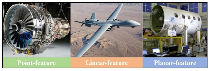
Figure 1Three types of aircraft components. The figure denoted as “Fig. 1” in the aforementioned paper is an original creation, authored and prepared entirely by the authors of this paper. It has not been previously published elsewhere, and it is not subject to any existing copyright held by a third party.
Currently, posture adjustment and positioning in aircraft assembly are primarily applied to planar-feature components, such as fuselage docking, wing docking, and wing fuselage docking. Such components typically employ parallel posture adjustment systems based on numerical control positioners (NCPs). Based on the specific dimensions and stiffness of the components, the posture adjustment systems can be further categorized into types encompassing three-point, four-point, and six-point support, among others. Among these, the four-point adjustment technology is the most widely adopted due to its optimal balance between system complexity and posture controllability (Zeng et al., 2020; Wang et al., 2023; Li et al., 2025a, c). However, significant limitations arise when applying these systems to the assembly of point-feature and linear-feature components, including insufficient flexibility, high costs, and spatial constraints for deployment. With the diversification and serialization of aircraft models, the demand for precise positioning and posture adjustment of point-feature and linear-feature components has become increasingly prominent, such as in the installation of weapon bay doors on new bombers, missile mounting, and cargo aircraft floor laying. In such confined working environments, traditional posture adjustment technologies are often inadequate due to insufficient installation space. Therefore, this paper focuses on posture adjustment technology suited for point-feature and linear-feature components.
Facing the aforementioned posture adjustment requirements, the Stewart platform, which combines structural stiffness with motion accuracy, demonstrates significant application potential. Its characteristics of compact structure, high precision, and reconfigurability make it suitable for precise posture control in confined spaces (Lu et al., 2020; Russo et al., 2024; Stewart, 1965; Dasgupta and Mruthyunjaya, 1998). However, despite some existing applications of parallel-mechanism-based adjustment technologies in certain aircraft components (Zhao et al., 2025; Ramirez and Wollnack, 2014; Erdem et al., 2016; Sun et al., 2012), their research and implementation for point-feature and linear-feature components remain notably insufficient, particularly in meeting the precision requirements within the confined spaces of new-generation aircraft models.
Given the low-rigidity characteristic of aircraft components, it is imperative to integrate force–position control into the posture adjustment system to ensure operational safety and to prevent structural damage. In the fields of robotics and precision motion control, force–position control technologies are mainly divided into two categories: impedance control and hybrid force–position control (Raibert and Craig, 1981; He et al., 2020; Hogan, 1984; Duan et al., 2018; Wang et al., 2024; Yu et al., 2026; Wang et al., 2026). Furthermore, beyond force–position control at the single-platform level, effective posture adjustment for complex components often necessitates the coordinated effort of multiple platforms, thus also involving multi-agent cooperative control technology (Sombolestan and Nguyen, 2023; Ji and Egerstedt, 2007; Kou et al., 2025; Chen et al., 2020; Shi and Yan, 2021). In the research of multi-agent cooperative control technology, the core methods can be summarized as follows: centralized and distributed optimal control, primary–secondary control, impedance control, task space decomposition-based control, and intelligent cooperative control methods (Zhu et al., 2020; Liu et al., 2025; Zhou et al., 2025; Jiang et al., 2023; Hu et al., 2020). Research on multi-agent collaborative control has predominantly focused on serial robotic arm systems, typically targeted at small, rigid objects. There remains a lack of force–position cooperative control methods for multi-parallel platforms handling large-scale, weakly rigid components (e.g., aircraft components) (Li et al., 2025b).
To address the aforementioned challenges, this paper investigates a cooperative posture adjustment technology with Stewart platforms as the actuators, targeting the assembly of point-feature and linear-feature components within confined spaces. The main contributions are as follows:
-
A primary–secondary cooperative framework based on admittance control is proposed. Within this framework, the primary platform performs position tracking, while the secondary platform implements compliant force control via an admittance model, achieving precise coordinated motion between multiple platforms without compromising component safety.
-
Building upon this framework, an H∞ robust controller is incorporated to suppress unmodeled dynamics and external disturbances, thereby ensuring control accuracy and stability in complex assembly environments.
The structure of this paper is organized as follows: Sect. 2 details the architecture of the Stewart platform, key technical specifications, and kinematic and dynamic modeling. In Sect. 3, we propose the force–position cooperative strategy based on primary–secondary admittance control. Section 4 describes the co-simulation environment setup and presents the results validating the effectiveness of the proposed approach. Finally, Sect. 5 provides concluding remarks and discusses potential future research directions.
2.1 Robot architecture and specification
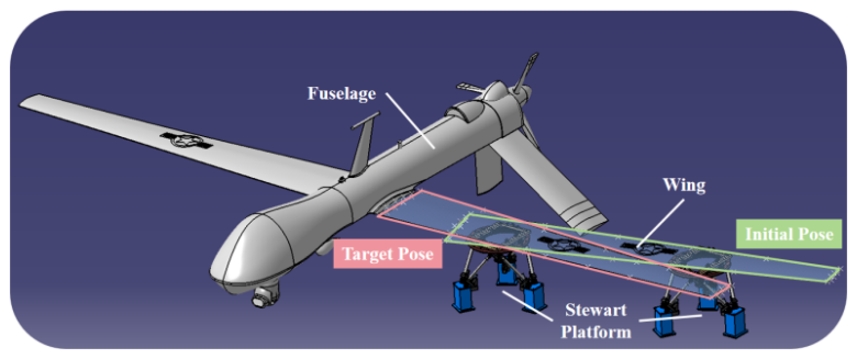
The ultimate objective of this research is to achieve high-precision coordinated posture adjustment for large-aircraft component assembly, using the wing fuselage assembly process as an application scenario, as illustrated in Fig. 2.
The focus of this paper is a dual-Stewart platform system for coordinated posture adjustment, as shown in Fig. 3a. Each Stewart platform in this system features a core mechanical structure that consists of a moving platform, a fixed platform, and six extensible legs connecting them, which is typically referred to as a six-UCU (where “U” stands for a hook joint, and “C” represents a cylindrical pair) kinematic configuration, as shown in Fig. 3b. Each leg is connected to the moving and fixed platforms via Hook joints (U joints) at both ends. When describing the Stewart platform, the moving-platform coordinate frame ({P} frame) is typically defined at the geometric center of the moving platform, and the fixed-platform coordinate frame ({B} frame) is fixed at the geometric center of the fixed platform. The moving attachment points ai () denote the three-dimensional coordinates of the rotation centers of the U joints on the moving platform in the {P} frame, while the fixed attachment points bi () represent the three-dimensional coordinates of the rotation centers of the U joints on the fixed platform in the {B} frame. The leg lengths are denoted as li (), as shown in Fig. 3c.
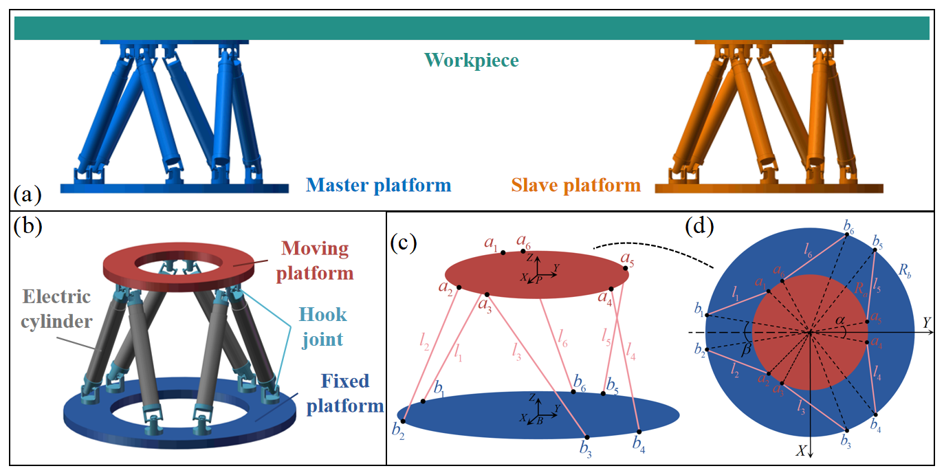
Figure 3Schematics of the Stewart platform. (a) Schematic of the overall layout. (b) CAD of the Stewart platform. (c) Schematic of the Stewart platform architecture. (d) Schematic of the attachment point distribution on the Stewart platform.
The attachment points on the Stewart platform are symmetrically distributed, forming a hexagonal shape. Herein, the moving attachment points ai () are distributed on a circle of radius Ra, with adjacent points being separated by an angle of α or 120°−α. Similarly, the fixed attachment points bi () lie on a circle of radius Rb, with adjacent points separated by an angle of β or 120°−β, as shown in Fig. 3d.
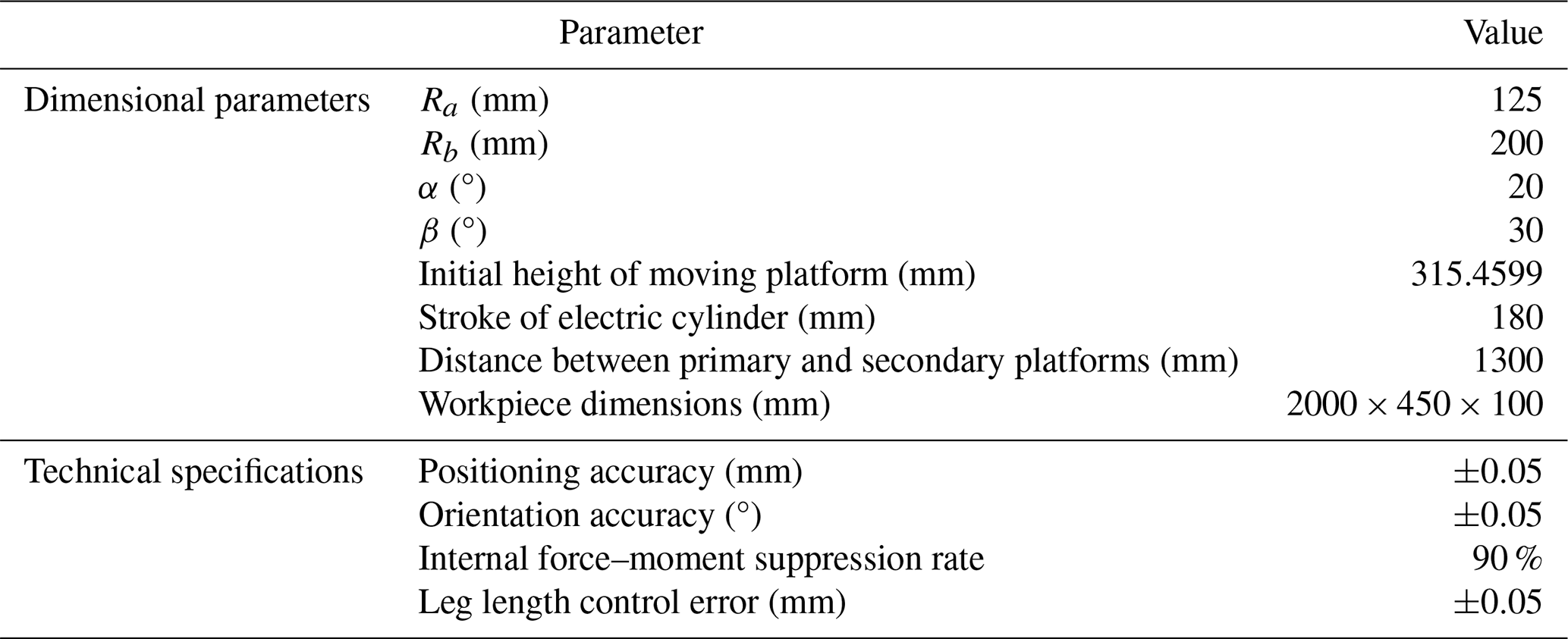
The key dimensional parameters and technical specifications are listed in Table 1. The technical specifications are determined based on the performance requirements of aircraft component assembly in the aviation industry, with reference to the positioning accuracy standards of high-precision NCPs.
2.2 Inverse kinematics model
The inverse kinematics modeling of the Stewart platform refers to the process of solving the required lengths of the six extensible legs, given the pose of the {P} frame relative to the {B} frame (. The spatial rotation is described using ZYX Euler angles, where the sequential rotation angles are φ about the X axis, θ about the Y axis, and Φ about the Z axis. The corresponding rotation matrix is given by the following:
where c and s denote the cosine and sine functions, respectively.
Based on Eq. (1) and the attachment points' coordinates, the coordinates of the moving attachment points in the {B} frame can be calculated as follows:
where is the translation vector from the pose .
Given the coordinates of the moving and fixed attachment points in the {B} frame, the length li () of each extensible leg can be computed. Furthermore, the Jacobian matrix J, which maps the platform's spatial velocity to the rates of change in leg lengths, can be derived.
In the above, ni () is the unit direction vector of the extensible leg.
2.3 Forward kinematics model
The forward kinematics modeling of the Stewart platform refers to the process of determining the pose q of the {P} frame relative to the {B} frame, given the lengths of the six extensible legs. Common solution methods include analytical, numerical, and intelligent algorithms. This paper adopts the quasi-Newton method for the solution. This method approximates derivative calculations using function value information, thereby avoiding complex differentiation and improving computational efficiency. For solving the forward kinematics of the Stewart platform, the core iterative formula is as follows:
where k is the iteration index, ΔAk is an approximation matrix for Ak, and F(qk) is the forward kinematics model function.
This paper employs the inverse Broyden method, an improved variant of the standard Broyden's algorithm, to design the approximation matrix ΔAk.
In the above, is the change in the independent variable, is the corresponding change in the function value, (sk)TBkyk≠, and the initial value for the matrix Bk can be set to the Jacobian matrix J.
2.4 Inverse dynamics model
The dynamic analysis of the Stewart platform can be performed using various methods, including the Newton–Euler equations, Lagrange's equations, Kane's method, and the principle of virtual work. In this section, a combined approach utilizing d'Alembert's principle and the Newton–Euler equations is adopted to establish the system's dynamic model. D'Alembert's principle transforms dynamic inertial effects into an equivalent static equilibrium problem, while the Newton–Euler equations recursively compute the forces and moments on each component. By integrating these two methods, inertial forces, driving forces, and constraint reactions can be intuitively separated, significantly simplifying the dynamic analysis of the multi-body coupled system.
By analyzing the velocities and accelerations of each extensible leg, the instantaneous motion states of all legs during system operation were determined, thereby concretizing the inertial force effects in d'Alembert's principle. On this basis, by performing a force and moment equilibrium analysis on the moving platform and the payload, we obtain the following:
where FC is the resultant force acting at the composite center of mass C of the moving platform and the payload, comprising inertial forces, gravitational force, and external forces; MC is the resultant moment acting at C, comprising inertial moments and external moments; c is the position vector of C, expressed in the {B} frame; and Fai and are the force and moment, respectively, exerted by the U joint of the moving platform on extensible leg i .
Furthermore, the decomposition of the resultant force Fai along the axial direction of the extensible leg and its perpendicular direction leads to the following expression:
where is the component of Fai perpendicular to the extensible-leg axis, and is the component of Fai along the extensible-leg axis (); they satisfy the relation of (). J denotes the Jacobian matrix defined earlier in Eq. (3).
Finally, performing a force analysis along the axis of extensible leg i () yields the required driving force τi:
where F2i is the sum of the gravitational force and inertial force of extensible leg i ().
To address the cooperative posture adjustment problem of dual-Stewart platforms, the primary–secondary control architecture simplifies coordination complexity by clearly dividing tasks (primary platform for decision-making, secondary platform for following) while maintaining compatibility with widely adopted industrial primary–secondary frameworks. On the other hand, admittance control leverages the multi-leg force sensor network of the Stewart platform to dynamically convert high-dimensional force feedback into pose compensation, enabling active compliance. This allows the platform to proactively “yield” during adjustment, thereby reducing workpiece stress and adapting to deformations and environmental uncertainties. The integration of both strategies ensures precise posture adjustment while enhancing workpiece safety. Thus, this paper adopts a force–position cooperative control strategy based on primary–secondary admittance control, where the primary platform operates in position control mode, and the secondary platform operates in admittance control mode. The system control block diagram is shown in Fig. 4.
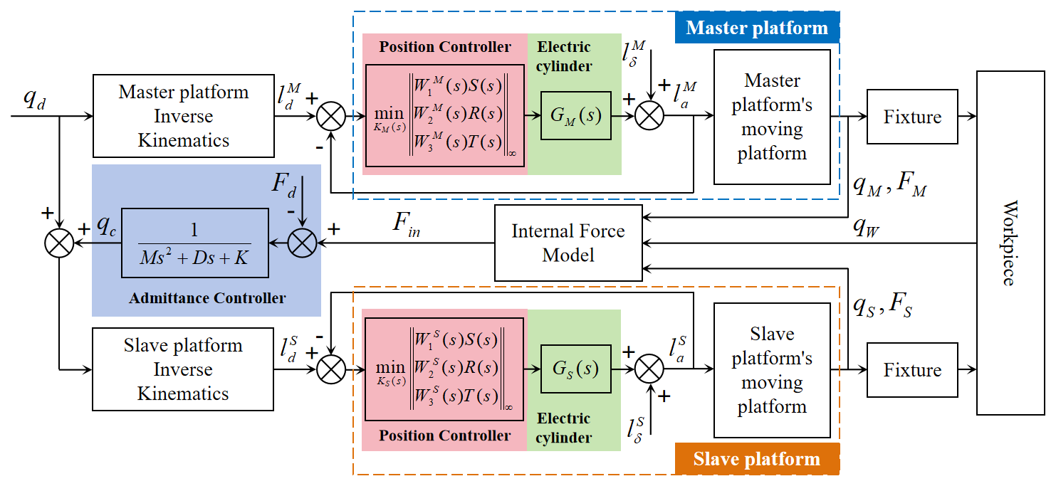
The control flow in the block diagram operates as follows. For the primary platform, the target pose qd for the moving platform is first generated based on task and trajectory planning. This pose qd is then mapped into the reference lengths for the six extensible legs via the inverse kinematics model. Finally, is fed into the position controller (an H∞ mixed-sensitivity controller), which produces corresponding control signals to actuate the electric cylinders, thereby moving the platform to achieve the target pose qd.
In contrast, for the primary platform, a pose compensation qc is added to the target pose qd. This compensation qc is generated by an admittance controller, which takes the internal force Fin from an internal force model as its input. The internal force model can generally be constructed in two ways: one is through direct modeling based on force analysis, and the other is through indirect modeling based on dynamic models or similar methods (the approach adopted in this paper will be introduced in Sect. 4.3). It should be noted that the input signals for the primary platform are the displacement curves of the six electric cylinders generated through trajectory planning. For the master platform, however, the input must additionally incorporate the pose compensation output from the admittance controller. In implementation, the displacement curves of the slave platform's electric cylinders are first converted into a pose via forward kinematics. After superimposing the compensation pose from the admittance controller, inverse kinematics is applied to finally derive the drive signals for the slave platform.
3.1 H∞ mixed-sensitivity position controller
The position control of parallel mechanisms is central to achieving their high-precision motion. The mechanism itself constitutes a complex, multi-input–multi-output (MIMO), strongly coupled, nonlinear system. Moreover, during actual operation, the system is subject to unmodeled dynamics, parameter variations, and external disturbances. Therefore, to realize high-precision, highly robust position control, this section introduces H∞ robust control theory.
The core idea of H∞ control is to design a controller that minimizes the H∞ norm of certain specified transfer functions of the closed-loop system, thereby reducing the worst-case impact of disturbances to a minimum. The mixed-sensitivity method is an effective and intuitive design approach within this framework, which satisfies different performance specifications by simultaneously optimizing multiple sensitivity functions. The block diagram of the H∞ mixed-sensitivity control is shown in Fig. 5.
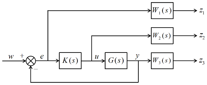
In the diagram: G(s) represents the plant; K(s) represents the controller; W1(s) is the performance weighting function, used to shape the closed-loop system's tracking performance and disturbance rejection capability; W2(s) is the control effort weighting function, used to constrain the amplitude and energy of the control signal; W3(s) is the robustness weighting function, used to enhance the system's robustness against model uncertainties (such as parameter variations and unmodeled dynamics); w denotes the generalized inputs, which include reference inputs, disturbances, and noise; e denotes the control error; u denotes the control input; y denotes the system output; z1 denotes the weighted error signal; z2 denotes the weighted control input signal; and z3 denotes the weighted system output signal.
Furthermore, the three sensitivity functions are defined as follows:
where S(s) denotes the sensitivity function, R(s) denotes the control sensitivity function, and T(s) denotes the complementary sensitivity function.
The objective of the H∞ mixed-sensitivity control is to find a controller K(s) that minimizes the H∞ norm of the weighted combination of sensitivity functions:
3.2 Admittance controller
Admittance control of the secondary platform establishes a mapping relationship between the interaction force and the compensated pose through a second-order dynamic model. The mathematical model is expressed as follows:
where is the pose compensation vector of the slave platform; are the mass, damping, and stiffness matrices characterizing the system dynamics, typically defined as diagonal matrices; is the generalized force deviation, defined as the difference between the internal force–moment Fin acting on the workpiece and the desired internal force–moment Fd (); and, in typical compliance control applications, the desired internal force–moment is often set to zero (Fd=0) to maximize workpiece protection. Under this setting, the force deviation ΔF is equivalent to the internal force–moment Fin.
To facilitate subsequent simulation analysis, the second-order differential equation is transformed into a state space representation. Defining the state variables x1=qc, , the system state equation is derived as follows:
and the standard state space representation of the system is given by
where I denotes the identity matrix of appropriate dimensions, u=ΔF denotes the system input, and y=qc denotes the system output.
4.1 Simulation method
To validate the performance of the aforementioned control method, a co-simulation control loop is established between Simulink and ADAMS, as illustrated in Fig. 6. In this loop, ADAMS transmits the state data of the mechanical system (e.g., pose, forces) to Simulink in real time. Simulink, in turn, utilizes these data as input for its controller to compute the control signals, which are sent back to ADAMS to close the loop. The co-simulation is configured to operate in discrete mode. The parameters are set as follows: a simulation step size of 0.001 s and a total duration of 4 s for Simulink and a communication interval of 0.001 s between Simulink and ADAMS.
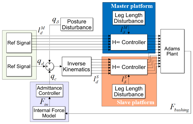
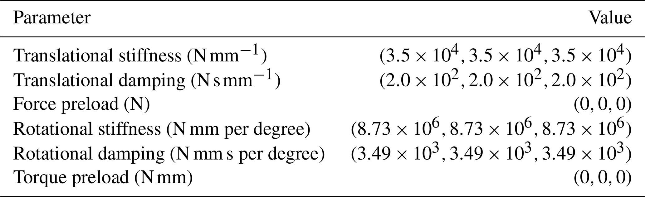
Specifically, to investigate the internal force–moments generated within the workpiece due to non-synchronous motion of the dual platforms, the connection methods between the platforms and the workpiece in ADAMS must be appropriately configured. If both connections were implemented as rigid fixed joints, even minor synchronization errors would result in an over-constrained system, leading to simulation failure. Therefore, a flexible connection scheme is adopted in this model: the primary platform is connected to the workpiece via a fixed joint, while the secondary platform is connected to the workpiece through a bushing force. The parameters for the bushing force in ADAMS are provided in Table 2.
Furthermore, to simulate the inevitable non-synchronous motion of the dual platforms during the actual alignment process, a pose disturbance signal is introduced into the command trajectory of the slave platform. This signal is designed as a composite signal consisting of two parts: a random spline curve and Gaussian noise. The spline curve ensures that the disturbance signal is smooth and continuous, preventing abrupt changes. Meanwhile, the Gaussian noise is employed to simulate random interference present in the actual environment. Simultaneously, based on the U-joint clearance model, the resulting leg length variation is incorporated into the control loop as an disturbance. This approach aims to better emulate real-world conditions and to validate the system's disturbance rejection capability. The dynamic response of the cooperative control system is provided in the Supplement (Video 1).
4.2 Position controller performance
We take the fixed-platform coordinate frame of the primary platform as the world coordinate frame ({W} frame). In the {W} frame, the initial pose of the workpiece is , and the target pose is set to . A desired trajectory, continuous and smooth in displacement, velocity, acceleration, and jerk, is generated based on a polynomial trajectory-planning method. Subsequently, the inverse kinematics solution is computed to derive the displacement drive commands for the electric cylinders of both the primary and secondary platforms, which serve as the coordinated control input for the system.
As outlined in Sect. 3.1, a prerequisite for designing the H∞ mixed-sensitivity controller is obtaining the transfer function of the controlled plant and designing the three weighting functions. At the drive level, a Stewart platform typically employs servo motors coupled with high-reduction-ratio planetary gearboxes or high-lead ball screws to drive the electric cylinders. Such high transmission ratio mechanical structures possess extremely high reverse undrivability and substantial equivalent rotational inertia. Consequently, the electrical dynamics of the motors and the linear displacement mapping of the ball screws constitute the dominant part of the system dynamics, resulting in a strongly diagonally dominant transfer function matrix for the system comprising six actuators. Based on this physical characteristic, each electric cylinder can be reasonably approximated as an independent second-order linear time-invariant (LTI) system. Those neglected off-diagonal coupled dynamic terms, unmodeled high-frequency flexible modes, and external load disturbances are uniformly abstracted as additive or multiplicative bounded unstructured uncertainties, to be suppressed by the subsequent H∞ robust control algorithm. To this end, using a step signal as the input and the displacement response of the electric cylinder from the ADAMS virtual prototype as the output, the transfer function of the electric cylinder is obtained through system identification as follows:
where a0=1, a1=1925, , and .
The weighting function was chosen in its canonical form, with parameters determined through a combination of theoretical analysis and iterative simulation. The final form of the weighting function is presented below:
Based on the identified plant model G(s) and the designed weighting functions W(s), the controller K(s) is obtained by solving the corresponding algebraic Riccati equations or linear matrix inequalities derived from the generalized plant structure.
A simulation model is constructed based on the aforementioned transfer function to validate the performance of the H∞ mixed-sensitivity controller. The results are shown in Fig. 7a and c. Analysis indicates that, although the tracking error exhibits some fluctuations during the initial and dynamic adjustment phases of the alignment process, it demonstrates excellent convergence. By the 4 s mark, the displacement tracking errors for all legs of both the primary and secondary platforms had stabilized within 0.05 mm, meeting the technical specifications outlined in Sect. 2.1 (Table 1).
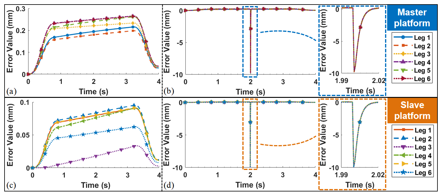
Figure 7Simulation results of the H∞ mixed-sensitivity controller. (a) Leg displacement tracking error of the master platform. (b) Leg displacement tracking error of the master platform (with step disturbance). (c) Leg displacement tracking error of the slave platform. (d) Leg displacement tracking error of the slave platform (with step disturbance).
Furthermore, to validate the robustness of the controller, a step signal with an amplitude of 10 mm is introduced as an external disturbance at the 2 s mark to observe the recovery of the system output. The final simulation results are shown in Fig. 7b and d. The results indicate that the H∞ mixed-sensitivity controller rapidly suppressed the oscillations induced by the disturbance (within approximately 0.02 s), enabling the system to quickly return to a stable tracking state. This demonstrates that the position controller designed based on the H∞ mixed-sensitivity method possesses strong disturbance rejection capability against external disturbances, meeting the requirements for high-precision pose adjustment.
4.3 Cooperative posture adjustment simulation
This section validates the overall performance of the proposed primary–secondary admittance control strategy for the dual-platform cooperative posture adjustment task, based on the co-simulation platform established in Sect. 4.1. The simulation focuses on two key metrics: the final positioning accuracy of the workpiece and the system's ability to suppress internal force–moment.
As described in Sect. 4.1, the internal force–moment Fin of the workpiece is indirectly observed via the bushing force in the ADAMS model (Table 2). To accurately isolate the undesired internal force–moment generated specifically by the motion asynchronization of the two platforms, a differential method is employed:
where Fmea is measured in real time through the bushing force model in ADAMS and represents a complex mixed term. Inevitably, it contains three core components: the gravitational component of the workpiece itself, the inertia force component generated as the workpiece follows the platform motion, and internal squeezing or pulling forces resulting from the motion asynchrony between the primary and secondary platforms. If Fmea is directly used as feedback input in admittance control, the secondary platform will mistakenly exhibit a “compliant” response to the workpiece's own weight, causing the workpiece to drop under gravity and thereby affecting trajectory accuracy. Therefore, the concept of a baseline synchronous force Fsync must be introduced. Fsync is the theoretical static and dynamic load that the slave platform would need to bear under a fully synchronized motion state to maintain the workpiece's current pose and desired kinematic state. By performing the differential calculation, the internal force Fin generated specifically by the motion asynchronization can be accurately isolated.
This method effectively eliminates the internal force–moment component caused by gravity and the initial configuration, ensuring that the observed force signal originates directly from the motion asynchronization between the two platforms. The dynamic characteristics of the admittance controller are determined by the mass (M), damping (D), and stiffness (K) matrices in Eq. (15). To achieve satisfactory force tracking performance and system stability, parameters were optimized through the system's dynamic response. The final admittance parameters were determined as follows:
where , , , , , and .
With the admittance controller implemented, a co-simulation of the entire cooperative adjustment process was conducted. The actual tracking trajectory of the workpiece from its initial to target pose is shown in Fig. 8a and b, and the internal force–moment variations are shown in Fig. 8c and d.
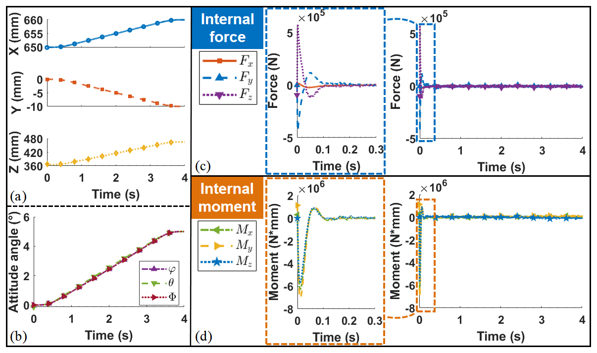
Figure 8Co-simulation results. (a) Actual displacement tracking curve of the workpiece. (b) Actual attitude angle tracking curve of the workpiece. (c) Internal force variations curve of the workpiece. (d) Internal moment variations curve of the workpiece.
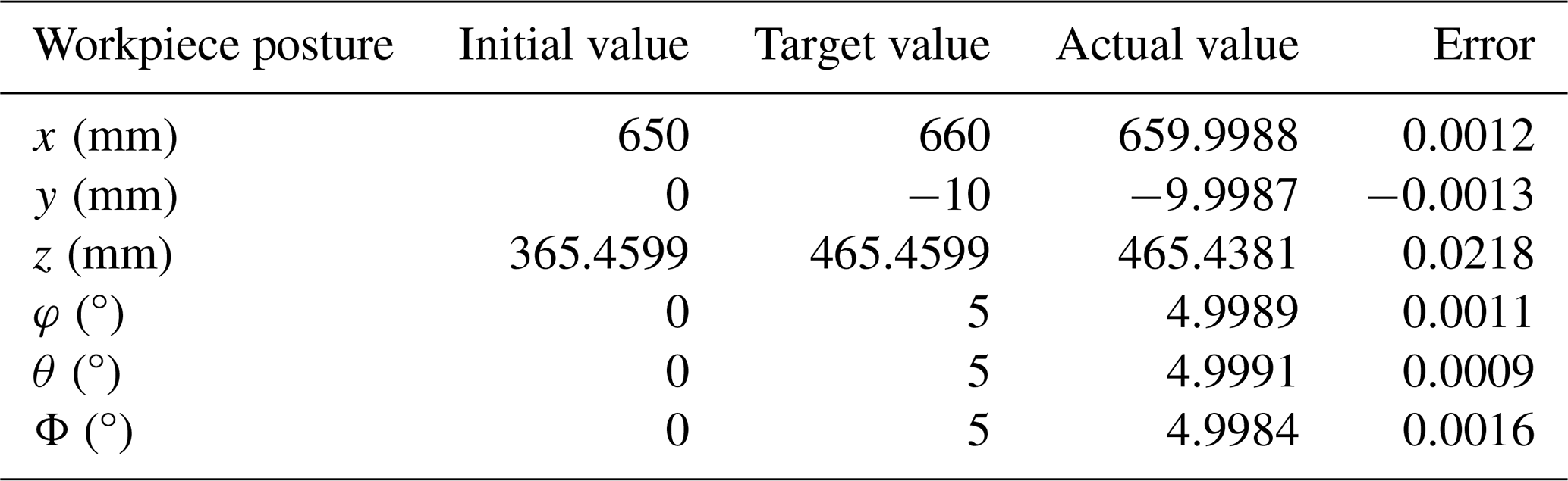
A quantitative analysis of the simulation data was performed, with the results summarized in Tables 3 and 4. The pose accuracy analysis (Table 3) demonstrates that, upon completion of the posture adjustment task, the positioning errors of the workpiece were consistently low. Specifically, the maximum translational error was 0.0218 mm in the Z direction, and the maximum attitude error was 0.0016° around the Z axis. These results fully confirm the high-precision performance of the control system.
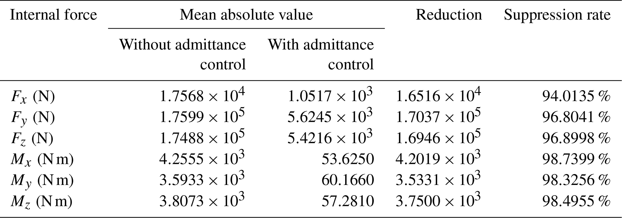
Table 5Design parameters for multiple sets of simulation experiment working conditions.
The internal force–moment suppression effect, detailed in Table 4, is even more remarkable. Compared to the scenario without admittance control, the introduction of the admittance controller successfully suppressed the internal force–moment in all directions to a significantly lower level, achieving a suppression rate exceeding 94.01 % across all measured components. This clearly indicates that the proposed primary–secondary admittance control strategy is highly effective in mitigating the internal force–moment generated by motion asynchronization between the two platforms.
In summary, the simulation results comprehensively validate that the system's performance meets the technical specifications outlined in Sect. 2.1 (Table 1), excelling in both posture adjustment accuracy and internal force–moment suppression capability.
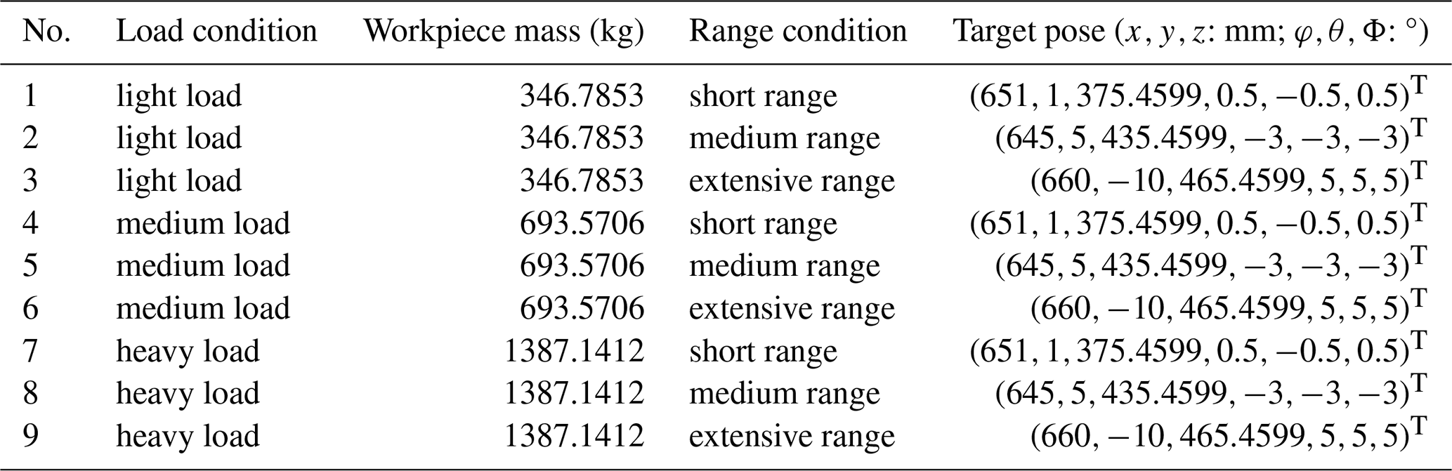
To validate the effectiveness and stability of the proposed control strategy under different operating conditions, multiple sets of simulation experiments were conducted further based on the aforementioned simulations. The simulation experiments were designed from two dimensions: load mass and pose adjustment range, resulting in nine different working conditions: (1) Load conditions are categorized into light load, medium load, and heavy load. Without altering the workpiece model, the density parameter was adjusted to simulate scenarios involving clamping components of different weights. (2) Range conditions are categorized into short range, medium range, and extensive range. This was achieved by setting different target poses for the workpiece. The range magnitude was measured by the required extension or retraction of each electric cylinder on the primary and secondary platforms, which directly reflects the utilization of the platform's driving mechanism within its physical stroke range.
Among them, the aforementioned simulation demonstrates the “medium load-extensive range” working condition. Under all working conditions, the same simulation environment settings, control algorithm parameters, and disturbance signals (Δq(t)) are maintained. The specific parameter designs for each working condition are shown in Table 5.
Table 6Workpiece posture error statistics under multiple working conditions.
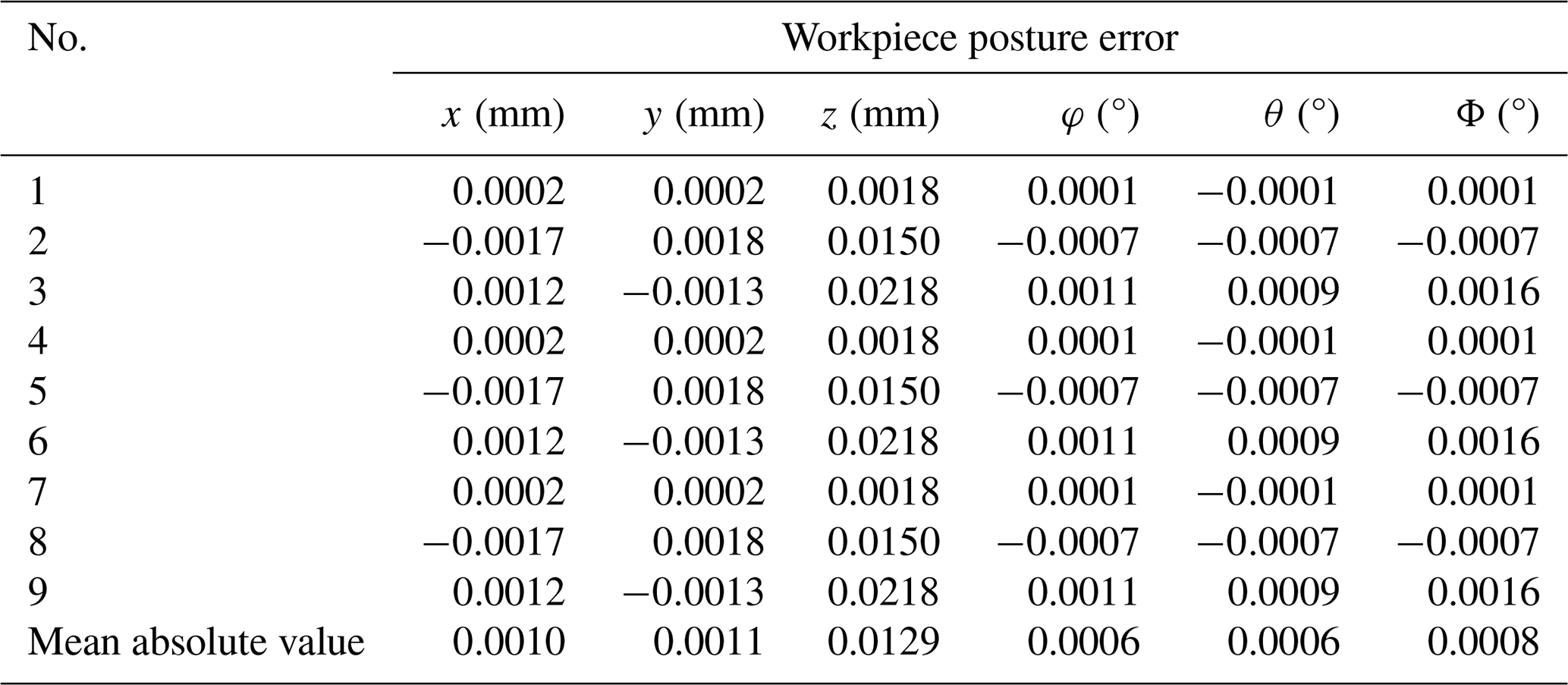
Table 7Workpiece internal force suppression rate statistics under multiple working conditions.

Furthermore, to evaluate the robustness of the proposed control strategy against fluctuations in controller parameters in practical engineering applications, piecewise time-varying random disturbances were introduced into the parameters of the admittance controller in the simulation. The specific design is as follows: the total duration of each simulation is evenly divided into 10 time segments. Within each segment, a random time point is selected, at which the mass, damping, and stiffness parameters of the admittance controller are instantly superimposed with a random disturbance value uniformly distributed within a ±5 % range. This disturbance remains constant throughout the segment until the next disturbance time point is triggered. This design aims to simulate the slow drift or step changes in controller parameters caused by factors such as component aging or environmental temperature variations, thereby testing the stability of the cooperative control strategy under non-ideal parameter conditions.
Data from all nine sets of simulation experiments were collected and analyzed. The summarized results of the core performance indicators (posture adjustment accuracy and internal force suppression effectiveness) are presented in Tables 6 and 7.
Based on the statistical data from Tables 6 and 7, the following conclusions can be drawn regarding the performance of the proposed control strategy under different working conditions: across the nine working conditions covering light, medium, and heavy loads, as well as small, medium, and large ranges, the final workpiece pose errors remain at a low level. As shown in Table 6, the mean absolute values of displacement errors in all directions do not exceed 0.0129 mm, and the mean absolute values of attitude angle errors do not exceed 0.0008°. This indicates that the designed H∞ mixed-sensitivity position controller exhibits good robustness against variations in load, motion range, and controller parameter fluctuations and can stably ensure high-precision trajectory tracking. Meanwhile, as seen in Table 7, the proposed admittance cooperative control strategy achieves highly efficient suppression of adjustment internal forces under all nine working conditions, with the suppression rates for internal forces and moments in all directions exceeding 90.03 %. The data show that, even in the presence of disturbances in the controller parameters, the internal force suppression performance does not significantly degrade, verifying its stability in internal force suppression.
In summary, the results of multiple sets of simulation experiments conducted under parameter disturbances demonstrate that the dual parallel platform cooperative pose adjustment strategy based on primary–secondary admittance control, as proposed in this paper, can achieve high-precision pose control and effective internal force suppression under various working conditions – from light to heavy loads and from small to large ranges. This fully meets the technical specifications outlined in Sect. 2.1 (Table 1).
This study addresses the challenge of precise posture adjustment for point-feature and linear-feature aircraft components in confined assembly spaces by proposing a dual-Stewart platform cooperative strategy based on primary–secondary admittance control. To enhance system robustness against parameter variations and external disturbances, the position controller was designed using the H∞ mixed-sensitivity method. Simulation results demonstrate that the proposed approach not only achieves high-precision pose control, with translational errors within 0.0218 mm and attitude errors within 0.0016°, but also effectively suppresses the internal force–moment caused by motion asynchronization between the two platforms, achieving a suppression rate of over 94.01 %.
Currently, research on posture adjustment technologies using parallel mechanisms for point-feature and linear-feature aircraft components remains limited, particularly in terms of multi-platform force–position cooperative control methods for large-sized, low-rigidity workpieces. Thus, the strategy presented in this paper offers a viable technical solution for high-precision, low-force assembly of such components in spatially confined environments, contributing to broadening the application of parallel mechanisms in aviation manufacturing. Future work will involve the construction of a physical platform to validate the control strategy under real-world conditions. Key research directions will include the following: (1) advancing the control architecture from unilateral admittance to bilateral compliance or shared impedance, incorporating differentiated stiffness settings for the primary–secondary platforms and delay compensation mechanisms (e.g., passivity observers, bandwidth adjustment) to enhance coordination and stability in practical operation; (2) implementing joint coordinate calibration for the Stewart platform and developing adaptive compensation strategies for multi-source errors (e.g., friction, backlash, crosstalk), potentially augmented by global measurement feedback, to bridge the sim-to-real gap; and (3) establishing a real-time internal force observation loop based on the physical force sensor network, utilizing methods such as inverse-dynamics difference or matrix null-space decomposition to replace the simulation-specific bushing model, thereby improving the reliability and practicality of internal force control.
Code and data are available on request from the authors. The datasets and the control code generated and analyzed during this study are not publicly available due to confidentiality agreements with our industrial partners and the proprietary nature of the aircraft components involved. However, processed data necessary to reproduce the key findings, along with a demonstration version of the control algorithm, are available from the corresponding author upon reasonable request for academic verification purposes.
The supplement related to this article is available online at https://doi.org/10.5194/ms-17-657-2026-supplement.
Methodology: HY and JL. Software: JL and KL. Validation: RT, KL, and PZ. Investigation: HY and PZ. Writing (original draft preparation): JL and PZ. Writing (review and editing): JL and PZ. Visualization: JL and PZ. Supervision: HY and RT. Project administration: HY. Funding acquisition: HY and RT. All of the authors reviewed and approved the final version of the paper.
At least one of the (co-)authors is a member of the editorial board of Mechanical Sciences. The peer-review process was guided by an independent editor, and the authors also have no other competing interests to declare.
Publisher's note: Copernicus Publications remains neutral with regard to jurisdictional claims made in the text, published maps, institutional affiliations, or any other geographical representation in this paper. The authors bear the ultimate responsibility for providing appropriate place names. Views expressed in the text are those of the authors and do not necessarily reflect the views of the publisher.
This research was supported 2024 “Hundred Doctors-Hundred Enterprises” Initiative under grant 2024H-100171; in part by the Shenzhen Science and Technology Program under grant KCXFZ20240903094011015; and in part by the Natural Science Foundation of Sichuan Province under grant 2026NSFSC1255.
This research was supported 2024 “Hundred Doctors-Hundred Enterprises” Initiative under grant no. 2024H-100171, in part by the Shenzhen Science and Technology Program under grant no. KCXFZ20240903094011015 and in part by the Natural Science Foundation of Sichuan Province under grant no. 2026NSFSC1255.
This paper was edited by Haitong Liang and reviewed by two anonymous referees.
Chen, Z., Huang, F. H., Yang, C. N., and Yao, B.: Adaptive fuzzy backstepping control for stable nonlinear bilateral teleoperation manipulators with enhanced transparency performance, IEEE T. Ind. Electron., 67, 746–756, https://doi.org/10.1109/TIE.2019.2898587, 2020.
Dasgupta, B. and Mruthyunjaya, T.-S.: A Newton–Euler formulation for the inverse dynamics of the Stewart platform manipulator, Mech. Mach. Theory, 33, 1135–1152, https://doi.org/10.1016/S0094-114X(97)00118-3, 1998.
Duan, J. J., Gan, Y. H., Chen, M., and Dai, X. Z.: Adaptive variable impedance control for dynamic contact force tracking in uncertain environment, Robot. Auton. Syst., 102, 54–65, https://doi.org/10.1016/j.robot.2018.01.009, 2018.
Erdem, I., Helgosson, P., and Kihlman, H.: Development of Automated Flexible Tooling as Enabler in Wing Box Assembly, Proc. CIRP, 44, 233–238, https://doi.org/10.1016/j.procir.2016.02.065, 2016.
Guo, F. Y., Xiao, Q. D., Xiao, S. H., and Wang, Z. Q.: Assembly technology for aeronautical CFRP structures under the collaborative constrains of geometric shape, physical performance and service stability, Compos. Struct., 318, 1–26, https://doi.org/10.1016/j.compstruct.2023.117071, 2023.
He, W., Xue, C. Q., Yu, X. B., Li, Z. J., and Yang, C. G.: Admittance-based controller design for physical human-robot interaction in the constrained task space, IEEE T. Autom. Sci. Eng., 17, 1937–1949, https://doi.org/10.1109/TASE.2020.2983225, 2020.
Hogan, N.: Impedance Control: An Approach to Manipulation, in: 1984 American Control Conference, San Diego, CA, USA, 6–8 June 1984, 304–313, https://doi.org/10.23919/ACC.1984.4788393, 1984.
Hu, J. Y., Niu, H. L., Carrasco, J., Lennox, B., and Arvin, F.: Voronoi-based multi-robot autonomous exploration in unknown environments via deep reinforcement learning, IEEE T. Veh. Technol., 69, 14413–14423, https://doi.org/10.1109/TVT.2020.3034800, 2020.
Ji, M. and Egerstedt, M.: Distributed Coordination Control of Multiagent Systems While Preserving Connectedness, IEEE T. Robot., 23, 693–703, https://doi.org/10.1109/TRO.2007.900638, 2007.
Jiang, A. M., Han, H., Han, C. Y., He, S., Xu, Z. B., and Wu, Q. W.: Dynamics modeling and redundant force optimization of modular combination parallel manipulator, Machines, 11, 1–19, https://doi.org/10.3390/machines11020247, 2023.
Kou, J. G., Wang, Y. X., Chen, Z. L., Shi, Y., and Guo, Q.: Gait planning and multimodal human-exoskeleton cooperative control based on central pattern generator, IEEE-ASME T. Mech., 30, 2598–2608, https://doi.org/10.1109/TMECH.2024.3453037, 2025.
Li, B., Tian, W., Zhang, C. F., Hua, F. F., Cui, G. Y., and Li, Y. F.: Positioning error compensation of an industrialrobot using neural networks and experimental study, Chinese J. Aeronaut., 35, 346–360, https://doi.org/10.1016/j.cja.2021.03.027, 2021.
Li, C. Y., Hu, J. S., Su, X. T., Wang, H. C., Liu, H. W., and Tian, W.: Analyses and regulations on deformation and stress of aircraft assembly structures with hybrid modeling strategy, Adv. Eng. Inform., 69, 1–27, https://doi.org/10.1016/j.aei.2025.104032, 2025a.
Li, X. F., Zhao, P. Y., and Jing, X. J.: X-Stewart mechanism for vibration isolation with nonlinear translational-to-rotational motion properties, Int. J. Mech. Sci., 303, 1–31, https://doi.org/10.1016/j.ijmecsci.2025.110596, 2025b.
Li, Y. J., Liu, W., Lu, H., Gao, C. Y., Liu, R. Z., and Chen, Q. H.: Online adaptive method for obtaining high-precision spherical joint positions with the lower internal force assembly of large-scale aircraft components, IEEE T. Ind. Inform., 21, 2194–2203, https://doi.org/10.1109/TII.2024.3495764, 2025c.
Liu, H. H., Zhen, S. C., Liu, X. L., Zheng, H. M., Gao, L. S., and Chen, Y.-H.: Robust approximate constraint following control design for collaborative robots system and experimental validation, Robotica, 42, 3957-3975, https://doi.org/10.1017/S0263574724001760, 2025.
Lu, Z.-Q., Wu, D., Ding, H., and Chen, L.-Q.: Vibration isolation and energy harvesting integrated in a Stewart platform with high static and low dynamic stiffness, Appl. Math. Model., 89, 249–267, https://doi.org/10.1016/j.apm.2020.07.060, 2020.
Raibert, M. H. and Craig, J. J.: Hybrid position/force control of manipulators, J. Dyn. Syst.-T. ASME, 103, 126-133, https://doi.org/10.1115/1.3139652, 1981.
Ramirez, J. and Wollnack, J.: Flexible automated assembly systems for large CFRP-structures, Procedia Technol., 15, 447–455, https://doi.org/10.1016/j.protcy.2014.09.004, 2014.
Russo, M., Zhang, D., Liu, X.-J., and Xie, Z. H.: A review of parallel kinematic machine tools: Design, modeling, and applications, Int. J. Mach. Tool Manu., 196, 1–22, https://doi.org/10.1016/j.ijmachtools.2024.104118, 2024.
Shi, P. and Yan, B.: A survey on intelligent control for multiagent systems, IEEE T. Syst. Man. Cy. A, 51, 161-175, https://doi.org/10.1109/TSMC.2020.3042823, 2021.
Sombolestan, M. and Nguyen, Q.: Hierarchical Adaptive Control for Collaborative Manipulation of a Rigid Object by Quadrupedal Robots, in: 2023 IEEE/RSJ International Conference on Intelligent Robots and Systems, Detroit, MI, USA, 1–5 October 2023, 2752–2759, https://doi.org/10.1109/IROS55552.2023.10341700, 2023.
Stewart, D.: A platform with six degrees of freedom, Proc. Inst. Mech. Eng., 180, 371–386, https://doi.org/10.1243/PIME_PROC_1965_180_029_02, 1965.
Sun, T., Song, Y. M., Dong, G., Lian, B. B., and Liu, J. P.: Optimal design of a parallel mechanism with three rotational degrees of freedom, Robot. CIM-Int. Manuf., 28, 500–508, https://doi.org/10.1016/j.rcim.2012.02.002, 2012.
Wang, J. Y., Tian, Y. Z., Xi, F. F., Chablat, D., Ren, G., and Zhao, Y. J.: A Pill bug-inspired Two-mode Mobile Robot Covered with Sliding Curvy Shells, IEEE T. Robot., 42, 1275–1289, https://doi.org/10.1109/TRO.2026.3661723, 2026.
Wang, M. C., Zong, L. J., and Yuan, J. P.: Position/Force Control for a Dual-Arm Space Manipulator Gripping and Transporting an Unknown Target Without Grapple Fixtures, IEEE T. Aero. Elec. Sys., 60, 1770–1783, https://doi.org/10.1109/TAES.2023.3341056, 2024.
Wang, Y., Liu, Y. P., Chen, H. H., Xie, Q., Zhang, K. J., and Wang, J.: Combined measurement based wing-fuselage assembly coordination via multiconstraint optimization, IEEE T. Instrum. Meas., 71, 1–16, https://doi.org/10.1109/TIM.2022.3186675, 2022.
Wang, Z. H., Li, H. B., and Sun, N. N.: High-efficiency inverse dynamics modeling of parallel posture alignment mechanism with actuation redundancy, Robotica, 41, 2668–2687, https://doi.org/10.1017/S0263574723000590, 2023.
Yu, H., Lv, M., Hu, B., Zhang, Y., and Zhao, P.: Review article: A review of control technologies for soft robots: from structural design to intelligent control, Mech. Sci., 17, 313–332, https://doi.org/10.5194/ms-17-313-2026, 2026.
Zeng, Q., Huang, X., Li, S. G., and Deng, Z. P.: High-efficiency posture prealignment method for large component assembly via iGPS and laser ranging, IEEE T. Instrum. Meas., 69, 5497–5510, https://doi.org/10.1109/TIM.2019.2958579, 2020.
Zhao, H. D., Li, L. P., Peng, Q. Y., Zhang, R. Q., Chen, T. D., Fang, F., Zhang, Q. J., Zhang, B. J., and Xiao, W. H.: Model based forward design of six degrees of freedom vibration isolator for aviation optoelectronic platform, Opt. Express, 33, 1–16, https://doi.org/10.1364/OE.564911, 2025.
Zhou, W., Tao, J. L., Yang, Z. J., Liu, W. Q., and Peng, J. Q.: Laparoscope adjustment with stereo vision for robot-assisted surgery based on multi-task control, IEEE Sens. J. (Early Access), 1–15, https://doi.org/10.1109/JSEN.2025.3582390, 2025.
Zhu, D. H., Feng, X. Z., Xu, X. H., Yang, Z. Y., Li, W. L., Yan, S. J., and Ding, H.: Robotic grinding of complex components: A step towards efficient and intelligent machining – challenges, solutions, and applications, Robot. CIM-Int. Manuf., 65, 1–15, https://doi.org/10.1016/j.rcim.2019.101908, 2020.