the Creative Commons Attribution 4.0 License.
the Creative Commons Attribution 4.0 License.
 | 27 May 2026
Multi-objective structural optimization of submarine cable pallet based on Kriging-MOPSO
Yuze Wang
Lijie Zuo
Changfang Zou
Cong Li
Hongliang Zhang
Yi Luo
Yunfei Ding
Zechen Qian
Yuhe Zou
Optimizing marine equipment is crucial for enhancing its overall performance, and numerous studies have explored the structural optimization of various marine systems. However, few investigations have focused on the design optimization of submarine cable pallets, despite their importance in marine operations. In this study, a static analysis of a submarine cable pallet under both lifting and transportation conditions was conducted using the finite-element method (FEM). The dimensions of key structural components were sampled using a design of experiment (DOE) approach. The resulting data were utilized to perform a sensitivity analysis on the pallet's performance indicators and to establish a surrogate model. This surrogate model was subsequently combined with a multi-objective particle swarm optimization (MOPSO) algorithm to optimize the pallet design. Specifically, the pallet base and the pallet fence were selected as the optimization targets under lifting and transportation conditions, respectively. The findings reveal significant improvements in the pallet's design, providing a valuable reference for the future structural engineering of submarine cable pallets.
- Article
(8726 KB) - Full-text XML
-
Supplement
(324 KB) - BibTeX
- EndNote


Driven by the rapid development of the marine economy, the demand for advanced marine equipment is steadily increasing. Consequently, structural optimization has emerged as a key research focus. Its objective is not merely to reduce equipment weight through material minimization, but to achieve minimal weight while maintaining or even enhancing critical mechanical properties, such as strength and stiffness. Ultimately, this approach satisfies the developmental requirements of marine equipment while promoting environmental sustainability and energy efficiency.
Recent advancements in computational capabilities have enabled the widespread application of simulation-based design optimization in marine engineering structures (Serani et al., 2024). Furthermore, several studies indicate that the integration of intelligent algorithms with parametric design significantly enhances both design efficiency and structural reliability (Xiao et al., 2024; Jarcă and Perijoc, 2023; Na and Karr, 2016).
For multi-objective optimization, a Pareto strategy was employed by Nazemian and Ghadimi (2020) to strike a balance between high-strength and lightweight requirements. In terms of hydrodynamic optimization, Abedin et al. (2024) utilized computational fluid dynamics (CFD) tools, specifically CAESES and STAR-CCM+, to optimize deep-sea trawlers, achieving notable improvements in seakeeping performance. Similarly, Pehlivan Solak (2020) developed a surrogate model to optimize the side hull configuration of trimarans, effectively reducing resistance and enhancing stability. Furthermore, the integration of intelligent algorithms has significantly boosted computational efficiency. For instance, the two-stage framework introduced by Abedin et al. (2024) increased computational efficiency by 40 %, while the high-fidelity surrogate model utilized by Pehlivan Solak (2020) for optimizing stern line shapes enhanced propulsion efficiency by 15 %.
The impact of various uncertainty factors on offshore wind turbine support structures was systematically quantified by Yu et al. (2023) using random variable modeling, Monte Carlo simulations, multi-limit state reliability analyses, and efficient radial basis function (RBF) surrogate models. While Monte Carlo simulations are highly effective for uncertainty quantification, advanced numerical design strategies from other transportation sectors offer valuable alternative perspectives. For example, Cascino et al. (2026) demonstrated that the topology optimization of railway motor supports – under manufacturing and adaptive stress constraints – provides a sophisticated framework for optimal material distribution. This approach ensures structural integrity under complex loading conditions while achieving extreme weight reduction. Such cross-disciplinary strategies highlight a critical evolution from simple parametric sensitivity studies to high-dimensional structural synthesis.
In the domain of surface ship propulsion, Wu et al. (2023) proposed a comprehensive optimization framework integrating CAD, CFD, design of experiments (DOEs), and particle swarm optimization (PSO). By selecting the tail propeller as the design object (with blade chord length and spacing as variables) and identifying the Kriging model as the most accurate surrogate model, they achieved remarkable improvements. Specifically, total resistance decreased by 23.99 %, single-propeller power consumption dropped by 3.55 %, and the tail propeller volume was reduced to 44 % of its original design. Furthermore, Jiang et al. (2023) introduced a dominant artificial bee colony (D-ABC) algorithm for multi-objective optimization. After validating its accuracy and convergence via benchmark functions, they applied this method to a chemical tanker's structural design, yielding a 5.08 % reduction in cross-sectional area and a 7.427 % decrease in the maximum vertical center of gravity height.
For anti-ship missile fuselage configurations under high-speed surface contact, Ye et al. (2023) developed a surrogate-model-assisted optimization method. By refining the sampling point selection for Kriging model construction, they significantly enhanced the prediction accuracy of target and constraint responses. The optimized fuselage reduced the maximum impact load by 17.4 % compared to the initial design and by 32.9 % relative to conventional configurations, thereby markedly boosting overall missile performance. Similarly, in the context of offshore wind turbine support structures, Rezvanipour et al. (2024) introduced a reliability-constrained optimization framework for lightweight design. By integrating finite-element analysis (FEA), genetic algorithms (GAs), and Monte Carlo simulation (MCS), this framework ensures that structural designs satisfy stringent performance and reliability standards while achieving mass reduction.
Topology optimization has been utilized to derive novel jacket foundation designs by identifying optimal load transmission paths within the structure (Marjan and Huang, 2023). For instance, computational simulations incorporating gas–water–servo-elastic loads were performed on the OC4 jacket model to generate a series of optimized configurations, with time-domain fatigue simulations conducted to evaluate structural integrity. Focusing on bottom-fixed offshore wind turbines in deep-sea environments, Tian et al. (2022) demonstrated that optimizing structural layouts can lead to enhanced performance, reduced weight, and lower costs. Their evaluation considered key indicators such as stability, ultimate strength, and natural frequency through limit state, eigenvalue, and buckling analyses.
In addition to wind turbine foundations, Romero-Tello et al. (2025) presented an optimization framework for pressure-resistant hull structures, aiming to minimize weight while adhering to DNV standards by integrating GAs with the FEM. Furthermore, the robustness of such numerical designs can be strengthened by incorporating advanced experimental monitoring technologies from other sectors. For example, the application of a 3D vision system for railway freight wagon monitoring (Luo et al., 1996) illustrates how real-time data acquisition can provide a comprehensive framework for validating simulated structural responses in complex environments. Integrating these experimental perspectives with numerical optimization ensures that derived designs are not only theoretically optimal but also practically reliable.
In this study, focusing on large submarine cable pallets, the flange and web thicknesses of the pallet base and the wall thicknesses of the fence circular tubes were selected as design variables. These selections were based on critical lifting and transportation conditions. A structural optimization framework was developed by combining a Kriging surrogate model with a multi-objective particle swarm optimization (MOPSO) algorithm. This approach optimized both the pallet base and the fence structure, aiming to minimize material consumption and manufacturing costs while simultaneously enhancing structural performance.
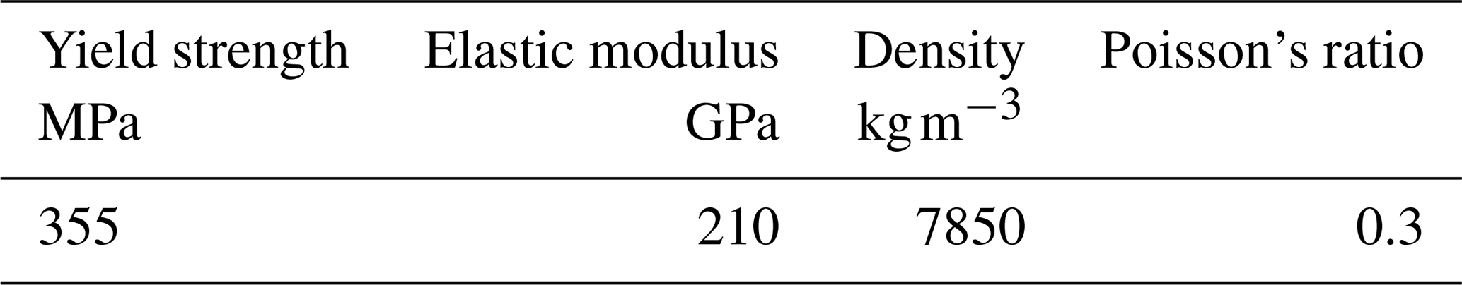
A large-scale submarine cable pallet with a loading capacity of 400 t was selected as the subject of this study. The finite-element model was developed using Abaqus software. The pallet structure primarily consists of a steel section base and a circular tube fence. To enhance computational efficiency, a hybrid modeling approach was adopted: line elements (beam elements) were utilized for the pallet fence, while shell elements were employed for the pallet base. These components were subsequently integrated into a comprehensive assembly within the Abaqus environment. Specifically, a tie constraint was established between the lower surface of the lifting eye and the upper surface of the base, and a coupling constraint was applied to connect the fence to the base surface. The primary material of the pallet is Q355 steel. The fundamental mechanical properties of Q355 were assigned to the model, as summarized in Table 1.
2.1 Lifting constraints
To simulate the lifting condition, the pallet was modeled using four slings with infinite stiffness, connecting a central hook point to the lifting eyes. In the finite-element model, coupling constraints were established between the hook point and the lifting eyes to represent the sling attachments. All translational and rotational degrees of freedom of the hook point were fully constrained in the x, y, and z directions to define the boundary conditions.
2.2 Lifting load analysis
Under the lifting condition, the total mass of the submarine cable is applied as a distributed load on the upper surface of the pallet base, specifically within the area between the inner and outer fences. In accordance with the DNV-ST-E273 standard, the design load, denoted as Fair, is calculated using Eq. (1). This definition and associated loading criteria are applied to all portable offshore units.
Here DF is the design factor, and MGW is the maximum gross weight of the marine equipment.
The design factor was defined based on the operating class and maximum gross weight (MGW). Given that the pallet is intended for onshore lifting operations, it was assigned an operating class of R00. For units with an MGW≥50 t, the design factor for this study was set to 1.5. The specific loads calculated for the lifting condition are summarized in Table 2.
Table 2Definitions of individual loads under the lifting condition.
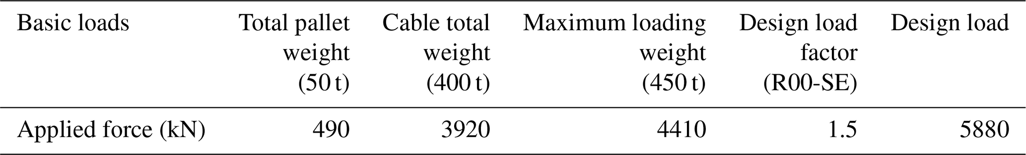
The design load was applied exclusively to the upper surface of the steel sections located between the inner and outer fences, with the purple arrows indicating the load distribution. The hook point was positioned directly above the geometric center of the pallet, and its vertical distance to the pallet base, denoted a z, was calculated using Eq. (2):
where a is the horizontal distance from the pallet center to the single hook point, α is the included angle between the slings and vertical direction, and H is the vertical height from the hook point center to the pallet base, as shown in Fig. 1.
In this model, a=5740 mm, α=30°, H=260 mm, and z=5213 mm.
2.3 Transportation constraints
Under transport conditions, the submarine cable pallet was positioned on the ship's deck. In the finite-element model, the vertical displacement of the bottom surface of the pallet base was constrained. The base was secured using stoppers located at each of its vertices. In accordance with the DNV-ST-E273 standard, three stoppers function as locators when the pallet is subjected to external loading. Consequently, the translational displacements of three stoppers were constrained. The corresponding boundary conditions, denoted as BC1, BC2, and BC3, were defined as Ux=0, Uy=0, and Uz=0 in the model.
2.4 Ship motion status under transportation condition
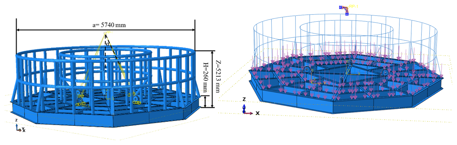
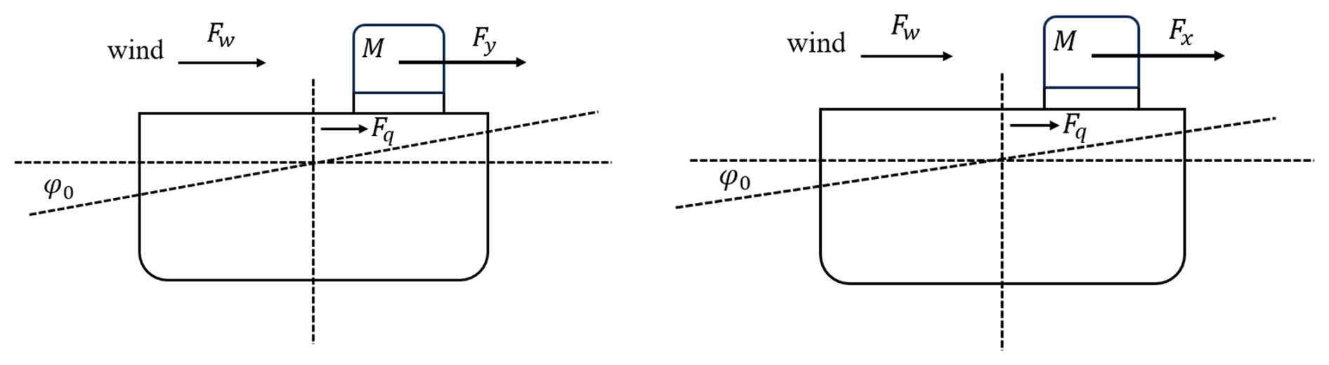
The center of rotation of the ship was assumed to be located at the intersection of its centerline and the horizontal plane of the deck. The motion-induced forces were calculated based on the mass of the submarine cable. The transport ship was modeled as a small vessel with an overall length of less than 76 m and a breadth of less than 23 m. Referring to the International Convention on Load Lines and incorporating conservative safety margins, the vertical height from the waterline to the main deck was assumed to be 8 m. According to the general arrangement drawing, the center of gravity of the pallet is located 1.68 m above the deck. During transportation, the pallet is primarily subjected to transverse forces induced by rolling acceleration and longitudinal forces induced by pitching acceleration; both sets of forces act parallel to the deck plane, as illustrated in Fig. 2.
Figure 2Schematic diagram of the forces acting on the ship under the transportation conditions.
2.4.1 Transverse force
The transverse force was determined by Eq. (3):
where M denotes the cable weight, Fw is the wind load, Fq is the sway force, and Ay is the transverse acceleration.
The submarine cable mass was 400 t; both the wind load and the sway force were applied as distributed pressures of 1 kN m−2, acting horizontally against the side of the pallet, parallel to the deck. However, the wind load was ultimately considered negligible and ignored in the calculations due to the highly skeletonized structure of the fences. In accordance with the DNV-ST-E273 standard, the transverse acceleration can be calculated using Eq. (4):
The parameters defined in Eq. (4) are illustrated in Fig. 3.
According to the default motion criteria DNV ND0030-3, φ0=30°, Tφ=10 s, and g=9.81 m s−2.
Then the transverse force Fy was calculated to be 2989 kN.
2.4.2 Longitudinal force
The longitudinal force was determined by Eq. (5):
The parameters are defined identically to those in Eq. (3).
The values of the wind load and swaying force are the same as those used in the calculation of the transverse force. Longitudinal acceleration was calculated using Eq. (6):
According to the default motion criteria DNV ND0030-3, φ0=15°, Tφ=10 s, and g=9.81 m s−2.
The longitudinal force Fx was calculated to be 1549 kN.
2.4.3 Vertical force
The vertical force along the Z axis was determined as the sum of the cable's weight and the vertical inertial force induced by the ship's motion, which was calculated using Eq. (7):
where M is the mass of the cable, g is gravity acceleration, and a is the inertial acceleration.
The maximum vertical force was calculated to be 4708 kN.
The loads and constraints applied to the model under transportation conditions are illustrated in Fig. 4. Displacements across all three degrees of freedom were constrained at the three stoppers. A vertical load was applied to the upper surface of the base, positioned between the inner and outer fences. Half of the horizontal load, Fy, was applied to the upper third of the inner pallet fence, while the remaining half was applied to the lower third of the outer pallet fence.
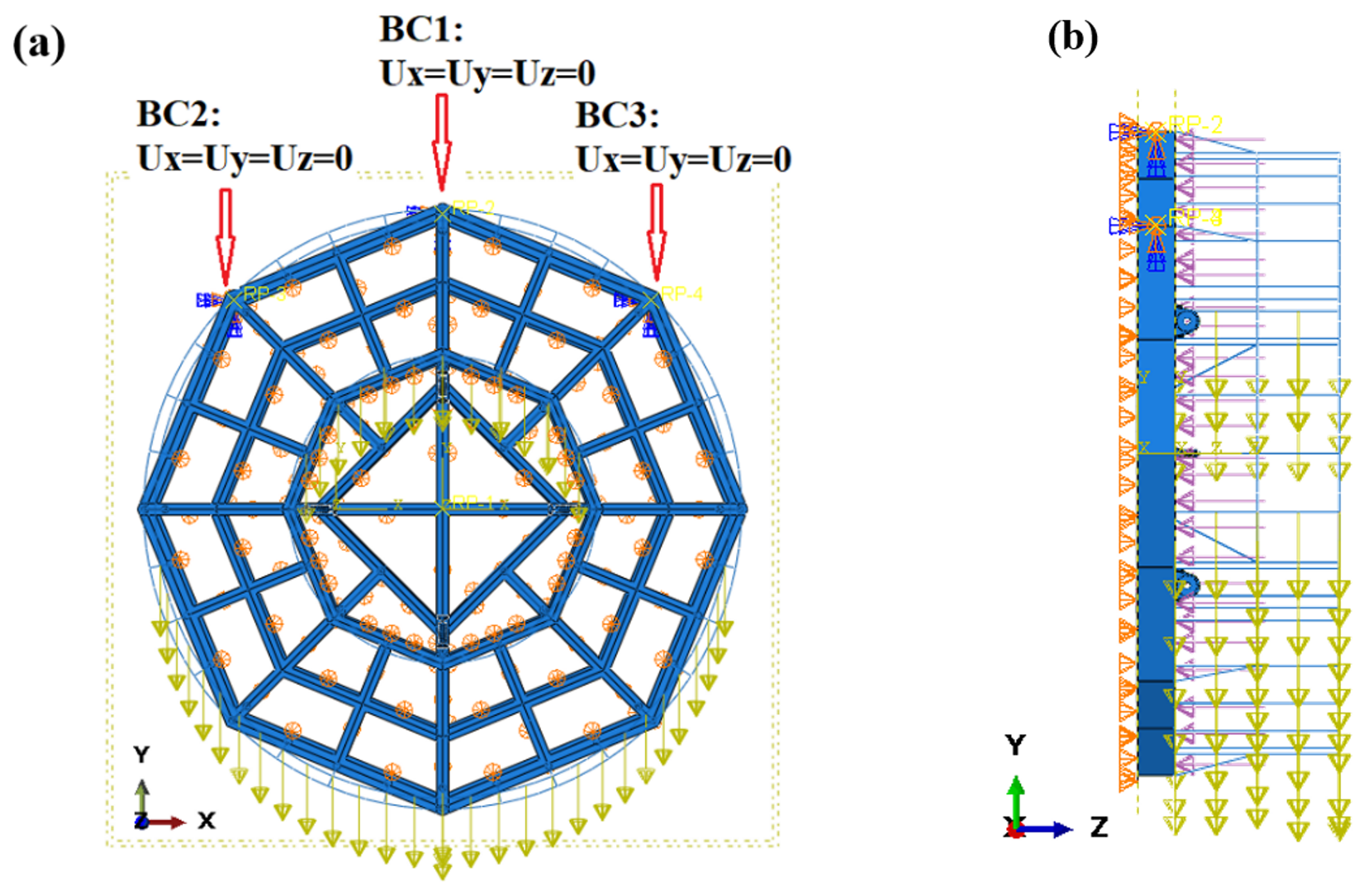
Figure 4Schematic diagram of the constraints and forces acting on the pallet under the transportation conditions.
3.1 Design of experiments
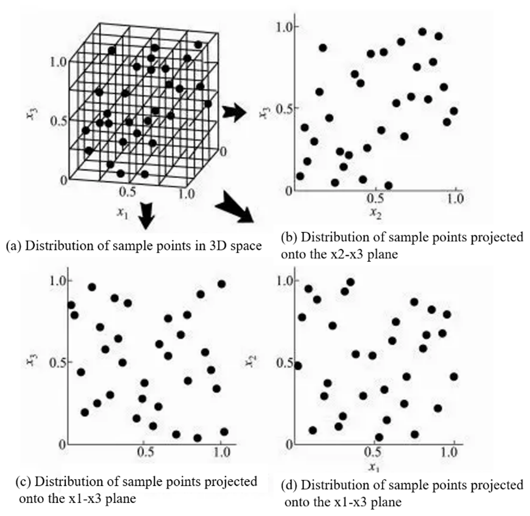
Design of experiments (DOEs) is a methodology founded on mathematical statistics, probability theory, and linear algebra. By employing this method, the effects of input parameters on output responses can be evaluated, and sample data for constructing a surrogate model can be generated (Kleijnen, 2008). In the structural optimization of ocean engineering equipment, the uniformity of the sampling points within the design space is crucial for the reliability of subsequent analyses. Therefore, Latin hypercube sampling (Mathé, 2000) was utilized for the experimental design in this study, as it is highly effective for scenarios involving a large number of samples and expansive design spaces. The sampling schematic of Latin hypercube is shown in Fig. 5.
3.2 Sensitivity analysis
In multi-objective optimization problems, inherent trade-offs exist among different objectives, making it impossible to find a single solution that simultaneously optimizes all of them. Therefore, conducting parameter sensitivity analysis to identify which parameters significantly influence the structural responses is of great importance.
Furthermore, the critical structural components of the pallet requiring evaluation varied between the lifting and transportation conditions; specifically, the base and the fence structures of the pallet bore the primary loads under these respective conditions.
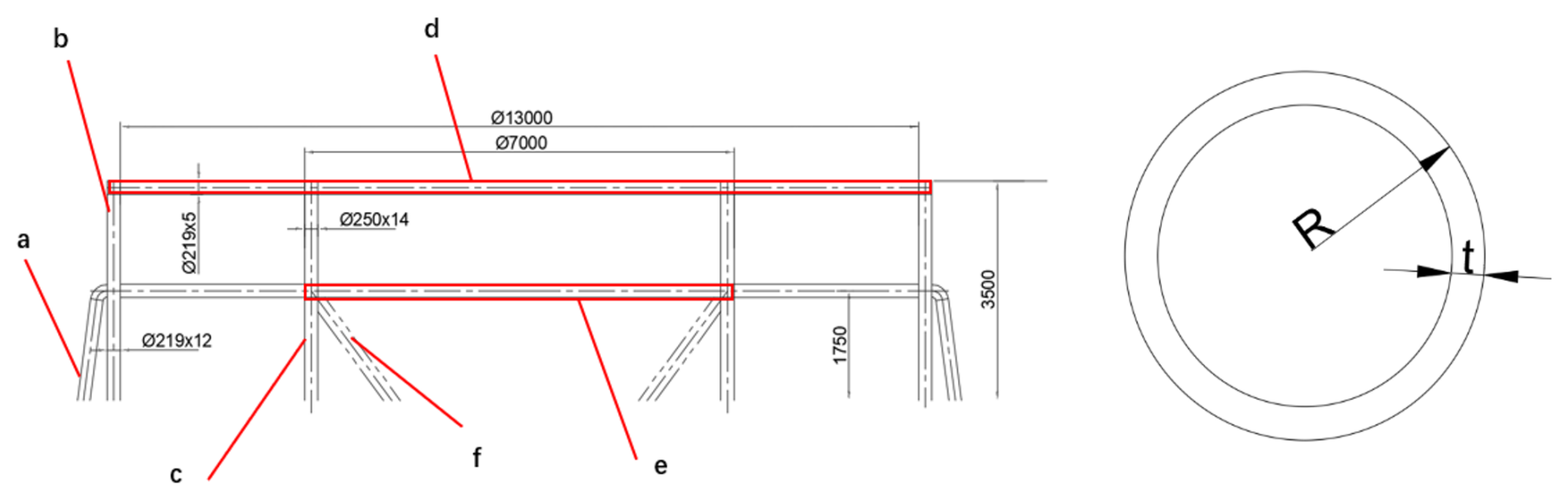
Given that the loading space of the pallet must remain constant, the web thickness, flange thickness, and tube wall thickness were selected as design variables. For the lifting condition, the pallet base structure was divided into eight sections. The web and flange thicknesses of the H beams were chosen as design variables based on their stress states during lifting while also accounting for manufacturing and processing characteristics, as illustrated in Fig. 6.
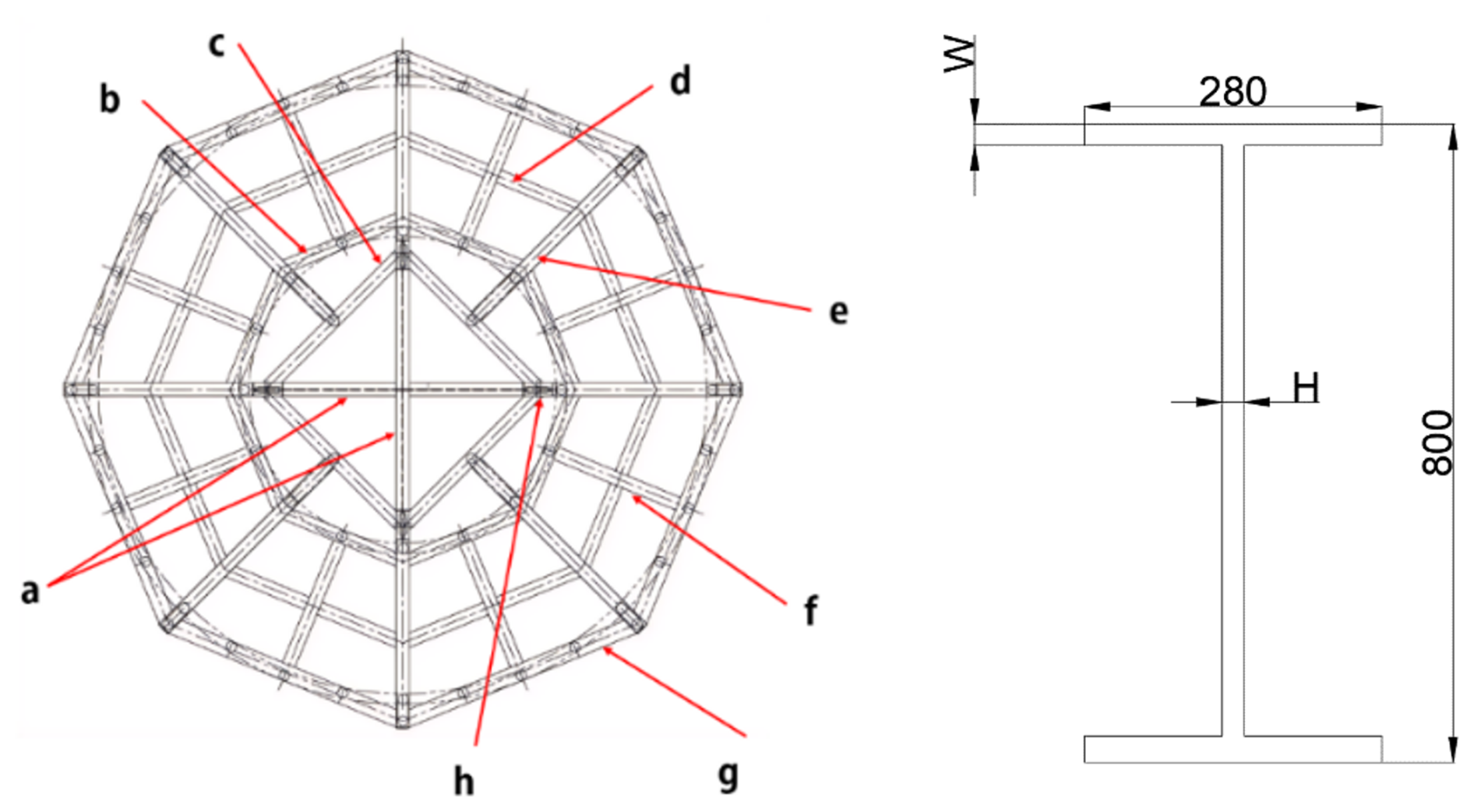
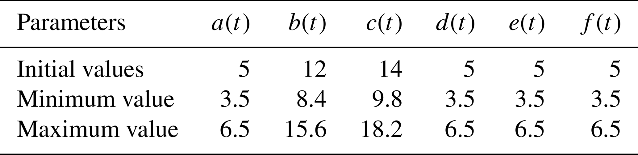
Under the transportation condition, the fence structure was divided into six sections, denoted as a, b, c, d, e, and f. Taking into account the applied loads during transportation and the manufacturing characteristics of the fence, the wall thickness of the circular tubes in each section was selected as the design variable. Consequently, a total of six design variables were established, as illustrated in Fig. 7. The specific sample data is presented in the Supplement.
For the 18 design variables under the lifting condition, 185 sample points were utilized to establish the response surface relationships between the design variables and key structural responses, such as mass, displacement, and stress. The resulting sensitivity values are illustrated in Fig. 8. Positive values indicate a positive correlation between the variables and the corresponding responses, whereas negative values signify a negative correlation. The sensitivity of each variable with respect to the structural responses is quantified using standardized regression coefficients. This quantitative metric provides a scientific basis for evaluating the impact of individual geometric parameters on the overall structural performance.
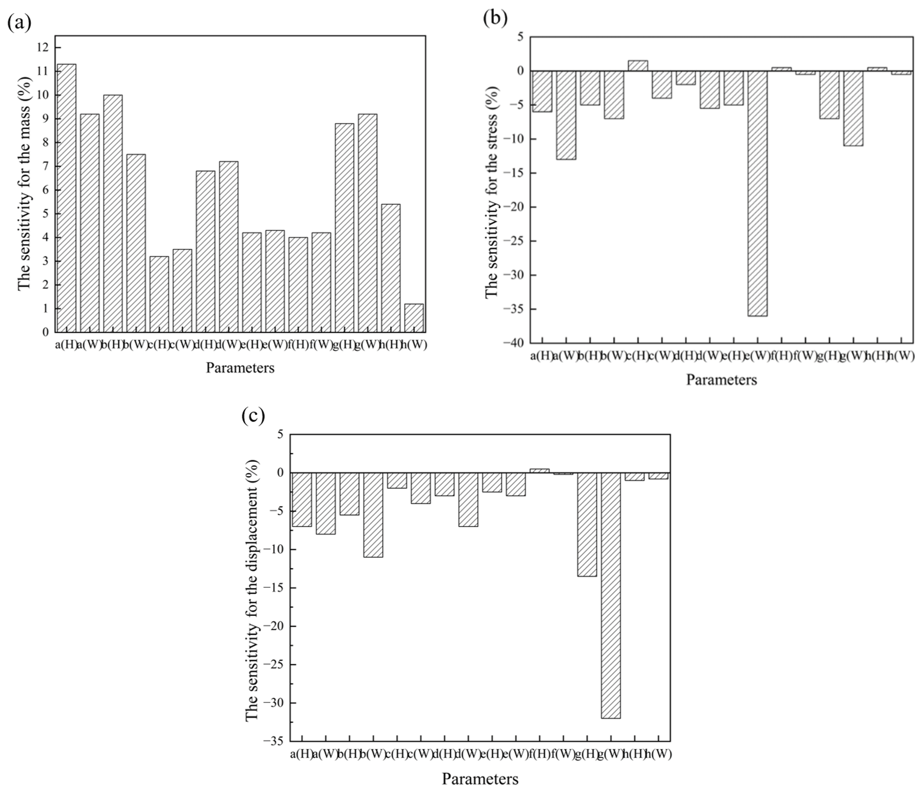
Figure 8Sensitivity values of the design variables to mass, stress, and displacement under the lifting condition.
As illustrated in Fig. 8, the sensitivities of the structural responses to the various design variables of the pallet base exhibited significant variations. The submarine cable is positioned between the inner and outer fences. Under the lifting condition, the weight of the submarine cable induces bending loads on the pallet base. These loads act directly on the flanges, making them critical load-bearing components of the base structure. Consequently, the geometric parameters of the flange exert a highly significant influence on the stress levels within the pallet base. Furthermore, the cross-sectional moment of inertia of the flange is substantially greater than that of the web; its superior bending stiffness primarily governs the overall structural deformation, thereby having a more pronounced effect on the displacement.
Flange e(W) connects multiple H-beam structures. The highly staggered arrangement in this area leads to stress concentrations, resulting in the highest stress sensitivity value. The maximum displacement occurred at flange G(W) because it is located at the extremity of the pallet base and is subjected to weaker boundary constraints. Webs a(H) and b(H), which account for the largest mass proportion in the pallet base structure, have a negligible impact on both stress and displacement. Furthermore, the mass sensitivities of web f(H) and flange f(W) were 0.04; however, their sensitivities regarding stress and displacement were both below 0.01. This distinct contrast provides a crucial direction for structural lightweighting.
For the six design variables under the transportation condition, 30 sample points were utilized to establish the response surface relationships between these design variables and key structural responses, such as mass, displacement, and stress, as illustrated in Fig. 9.
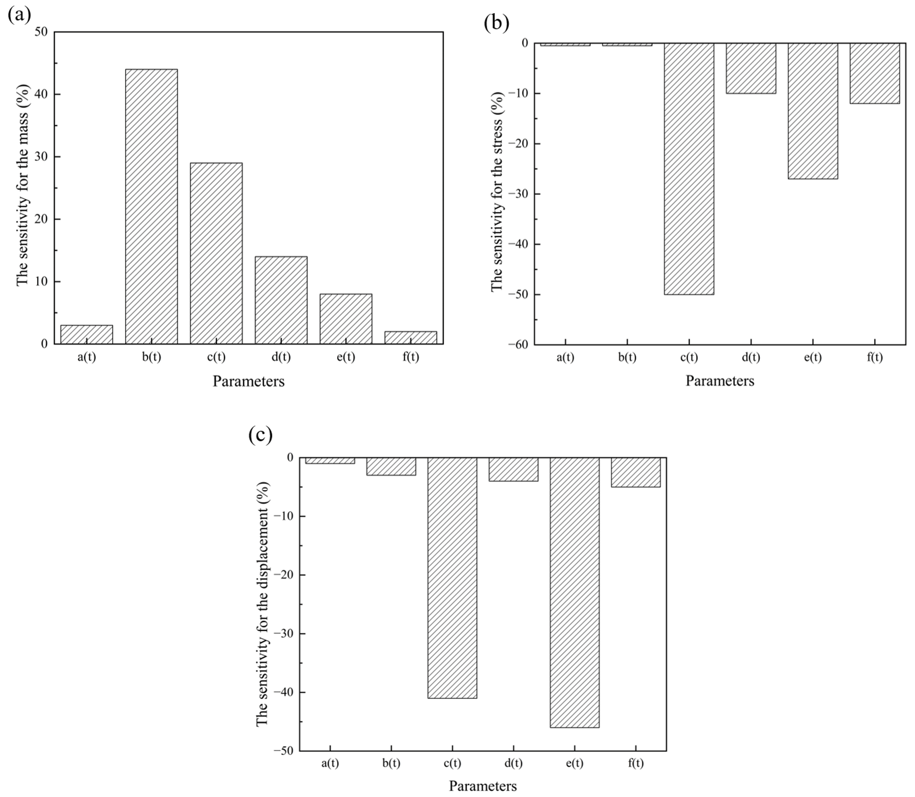
Figure 9Sensitivity values of the design variables to mass, stress, and displacement under the transportation condition.
The wall thicknesses of the circular tubes in various sections of the fence exert varying degrees of influence on structural responses such as mass, stress, and displacement. The maximum stress occurred at the connection interface between the inner vertical tube and the pallet base, while the maximum displacement was observed on the inner fence. Based on the sensitivity analysis, the wall thicknesses of sections c(t) and e(t) exhibited highly sensitive characteristics for both stress and displacement. Specifically, their stress sensitivities were 0.48 and 0.41, while their displacement sensitivities were 0.40 and 0.45, respectively.
Consequently, serving as the primary support structure, the inner vertical fence can alter the stress transfer path through an effective increase in wall thickness, thereby mitigating stress concentrations at the connection interface between the base and the fence. Simultaneously, increasing the wall thickness of the inner transverse fence enhances its bending stiffness and improves its capacity to restrain the submarine cable. When the fence is subjected to transverse forces, structural displacement is effectively constrained, thereby enhancing the overall stability of the pallet.
When subjected to transverse loads, the inner tilted fence pipes exhibited a significant stress redistribution capability, resulting in a more uniform stress distribution and a reduction in structural stress concentrations. In addition, these tilted pipes, together with the vertical and transverse fence pipes, formed a spatial frame structure, which significantly contributed to restricting the overall structural displacement.
In contrast, the wall thickness of the outer fence, b(t), had a minimal effect on both stress and displacement, despite accounting for the largest mass proportion within the fence structure. Furthermore, the outer fence is subjected to only 50 % of the line load compared to the inner fence, and its stress distribution is more dispersed. Therefore, the design of the outer vertical fence can be optimized to achieve structural lightweighting without compromising overall performance.
3.3 Size design variable
To achieve structural lightweighting and displacement reduction, 16 variables from 8 regions of the pallet base and 6 variables from 6 regions of the pallet fence were selected as the design variables for optimization.
The design variable ranges were established based on component criticality and manufacturing constraints. The base profiles, serving as primary load-bearing members, were assigned a conservative ±10 % range to maintain high structural reliability and compatibility with standard steel profiles. In contrast, the fence pipes, acting as secondary retaining members, were allocated a broader range of ±30 % to maximize the lightweighting potential while remaining within the limits of standard commercial pipe thicknesses.
The size parameters are listed in Tables 3 and 4, respectively. The upper and lower limits of the base variables were ±10 % of their baseline values, whereas the limits for the fence variables were established at ±30 % of their baseline values.
Table 3Variation range of the optimized dimensional parameters for the base (in mm).
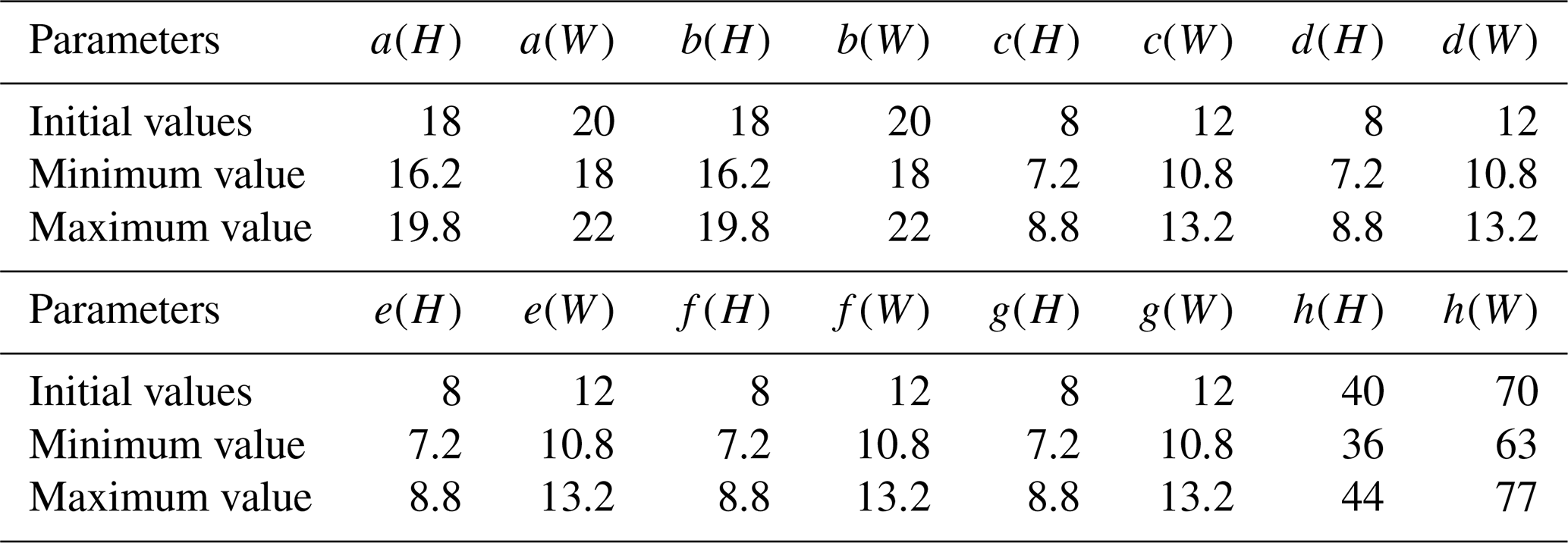
Table 4Variation range of the optimized dimensional parameters for the fence (in mm).
3.4 Mathematical models
A mathematical optimization model for the pallet was established based on key performance indicators, including structural mass, displacement, and stress:
where F(x) is the objective function; M(x) and U(x) are the structural mass and maximum displacement after optimization, respectively; M(Xi) and U(Xi) are the initial mass and initial maximum displacement of the structure, respectively; and ωi and ωj are the weighting factors.
Given the multi-objective nature of the optimization, both weighting factors, ωi and ωj, were set to 0.5.
First, the preliminary sensitivity analysis demonstrated that both mass and displacement were highly sensitive to the design variables, indicating that they are critical optimization objectives warranting equal consideration. Second, for large-scale structures such as submarine cable pallets, achieving a lightweight design and maintaining sufficient stiffness hold comparable importance in engineering practice. Finally, in the absence of explicit prior preferences, assigning equal weights served as a standard and rational baseline approach. This strategy aimed to identify a compromise solution that significantly improved both objectives simultaneously.
Based on the established objective function, the optimal design is achieved when F(x) is minimized. Under the lifting condition, the mass of the pallet base and the corresponding constraints can be described by the following mathematical expressions:
Under the transportation condition, the mass of the pallet base and corresponding constraints can be described by the following mathematical expressions:
3.5 Approximation model
A surrogate model was constructed using the design of experiment (DOE) approach, yielding results that closely approximated those of the finite-element analysis (FEA) (Kleijnen, 2017). By replacing computationally expensive finite-element numerical analyses, this surrogate model significantly enhanced the efficiency of the optimization process. The spatial distributions of the stress, mass, and displacement indicators, derived from the sampling data points, are illustrated in Fig. 10. It can be observed that these three indicators – mass, displacement, and stress – are conflicting objectives.
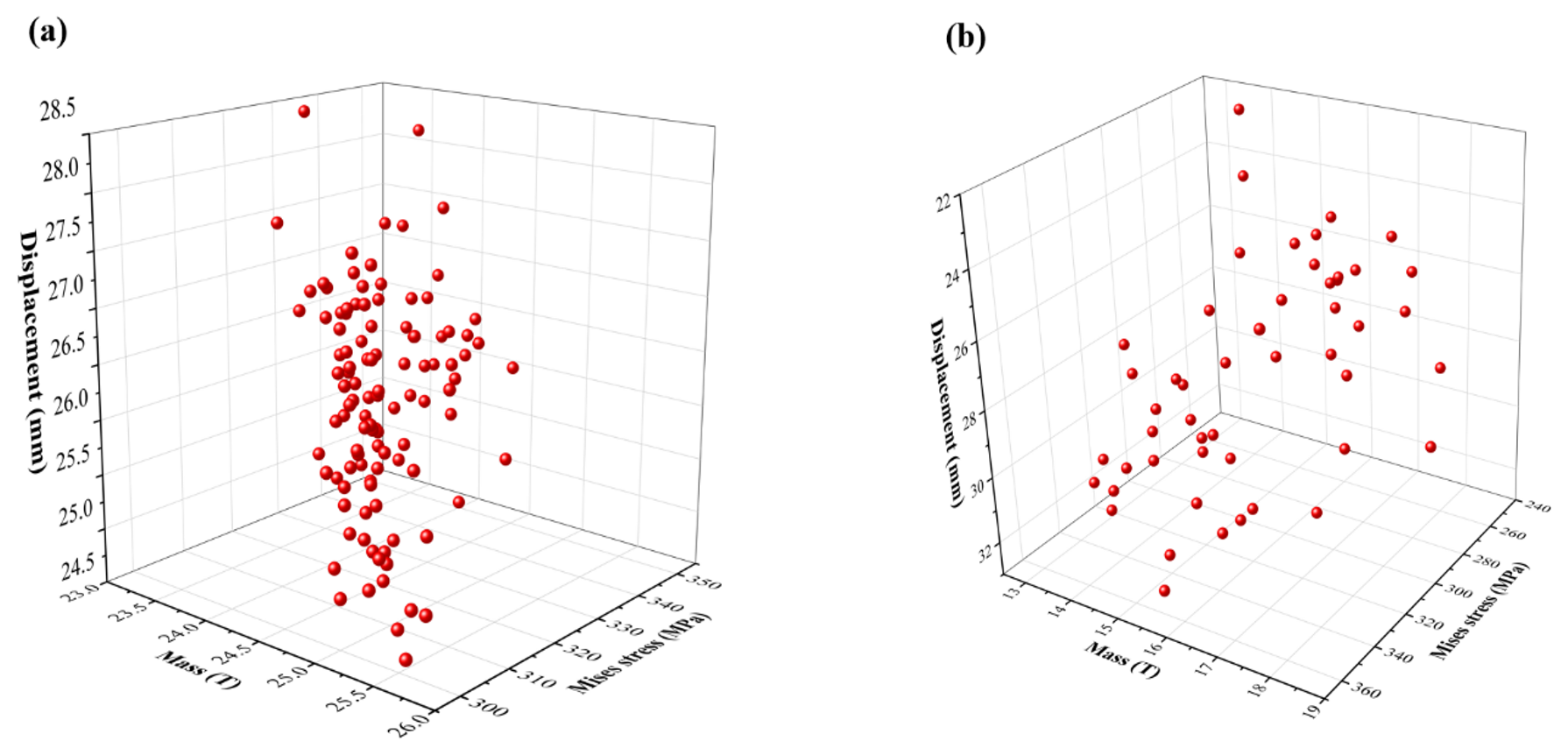
Figure 10Spatial distribution diagrams of pallet mass, stress, and displacement under lifting and transportation conditions.
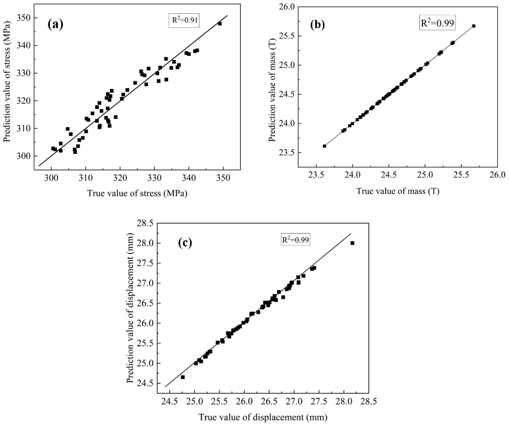
Figure 11Prediction accuracy of the universal Kriging model for mass, stress, and displacement responses under the lifting condition.
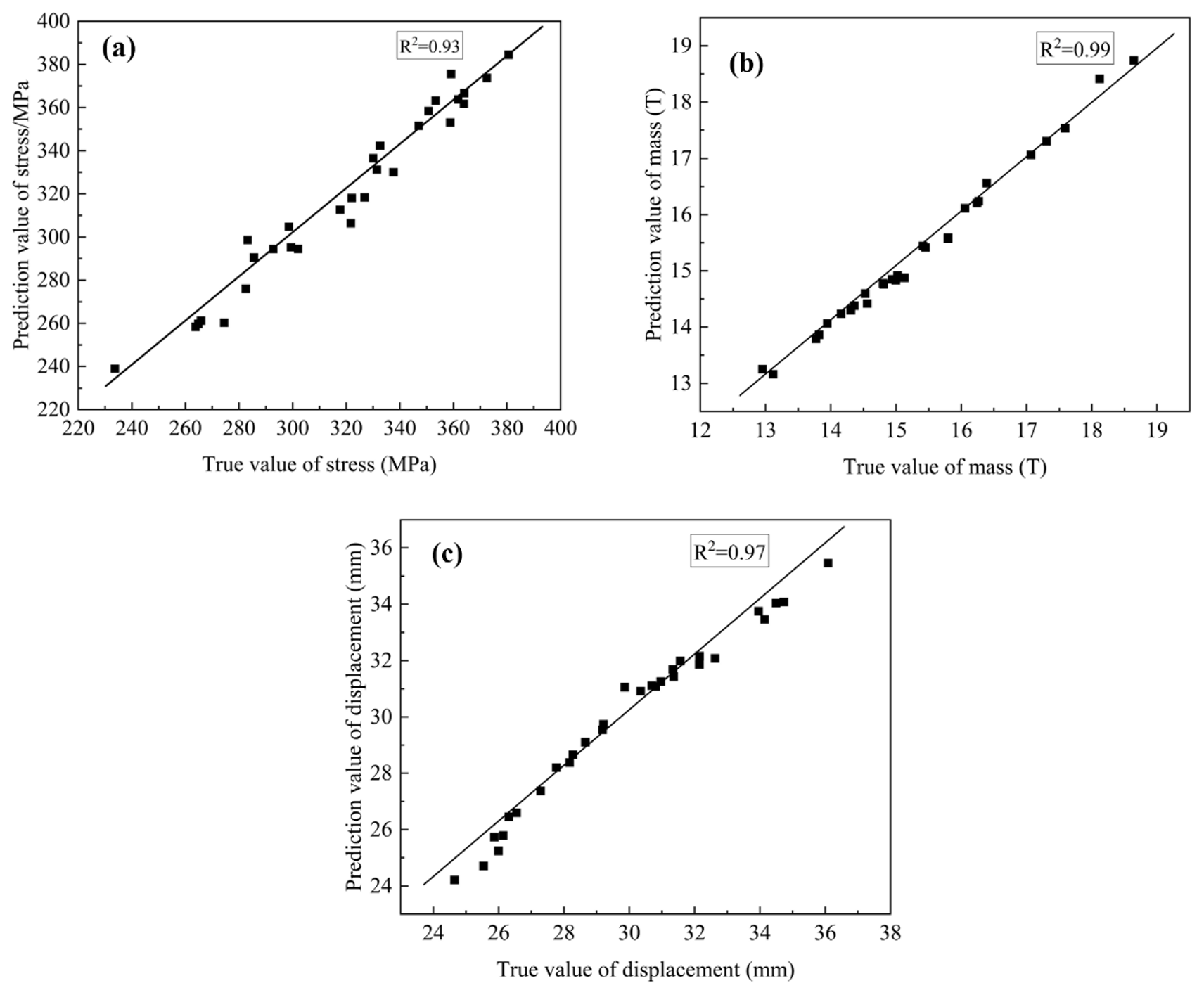
Figure 12Prediction accuracy of the universal Kriging model for mass, stress, and displacement responses under the transportation condition.
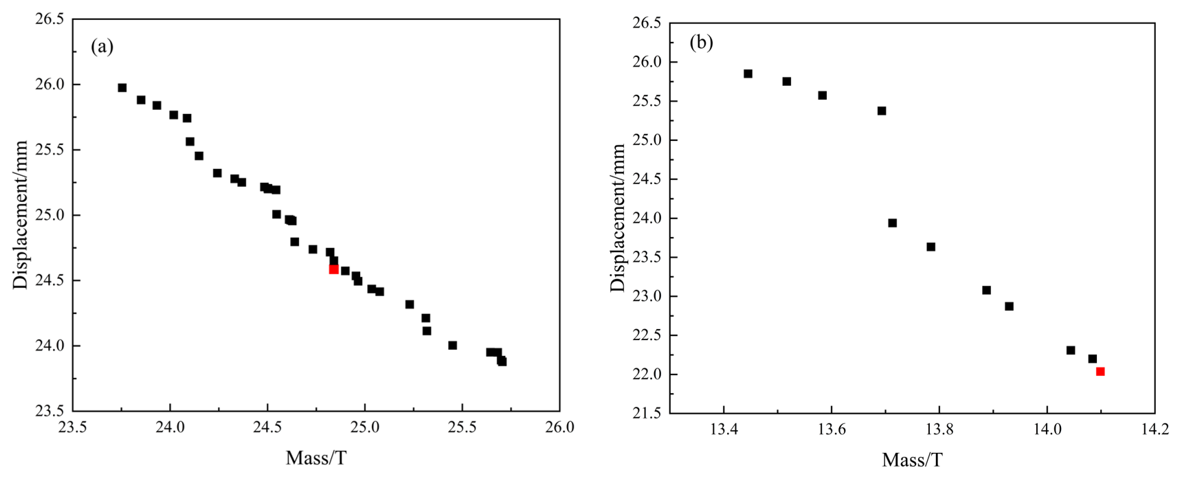
Figure 13Pareto chart of pallet mass and displacement under lifting and transportation conditions.
Table 5Optimization results of the pallet base design variable (in mm).
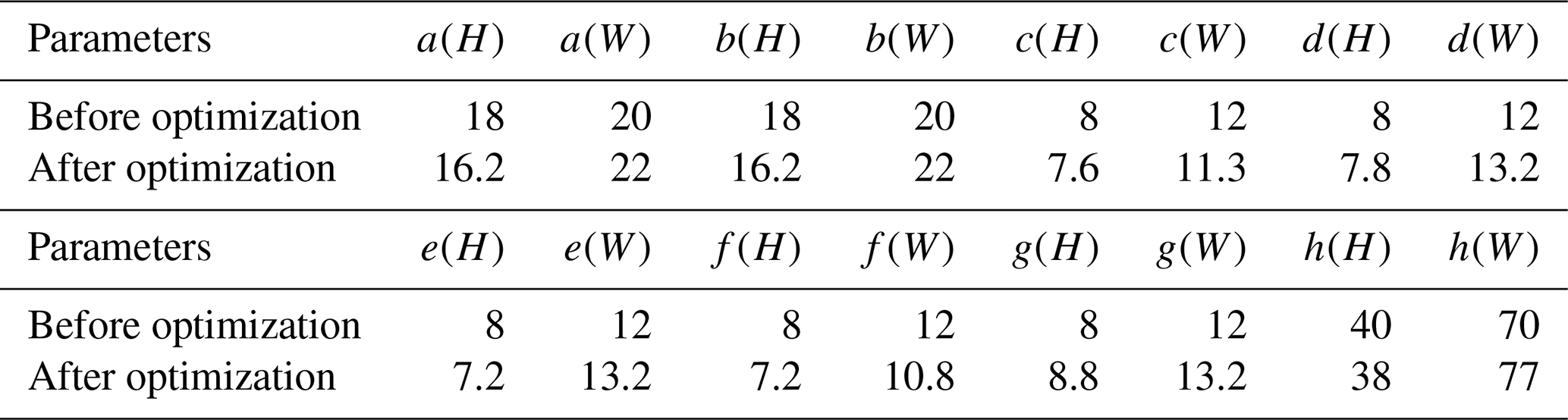
Table 6Optimization results of the pallet fence design variable (in mm).
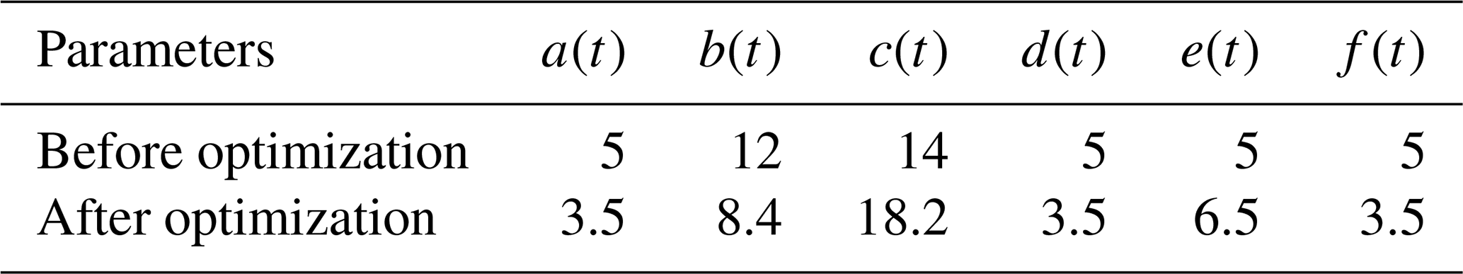
Table 7Comparison of the performance indicators values before and after structural optimization.
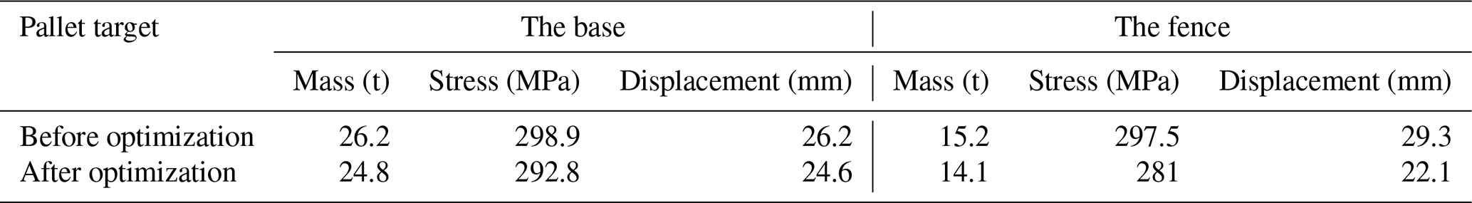
Table 8Comparison of the results between the surrogate model and finite-element analysis under the lifting and transportation conditions.
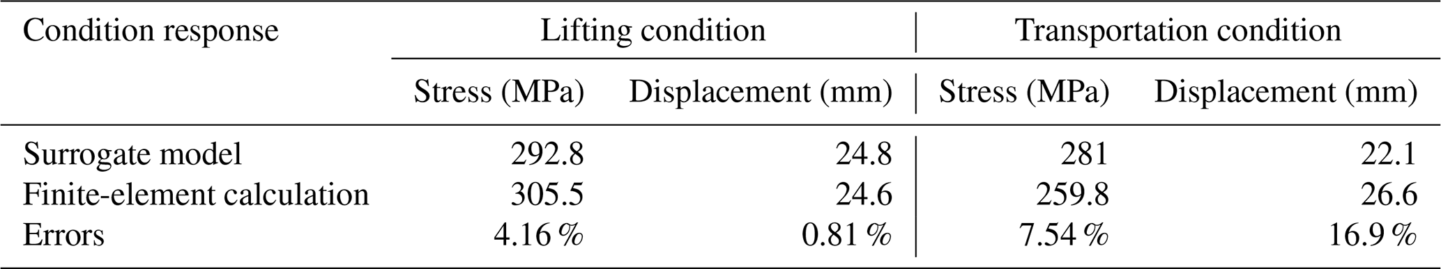
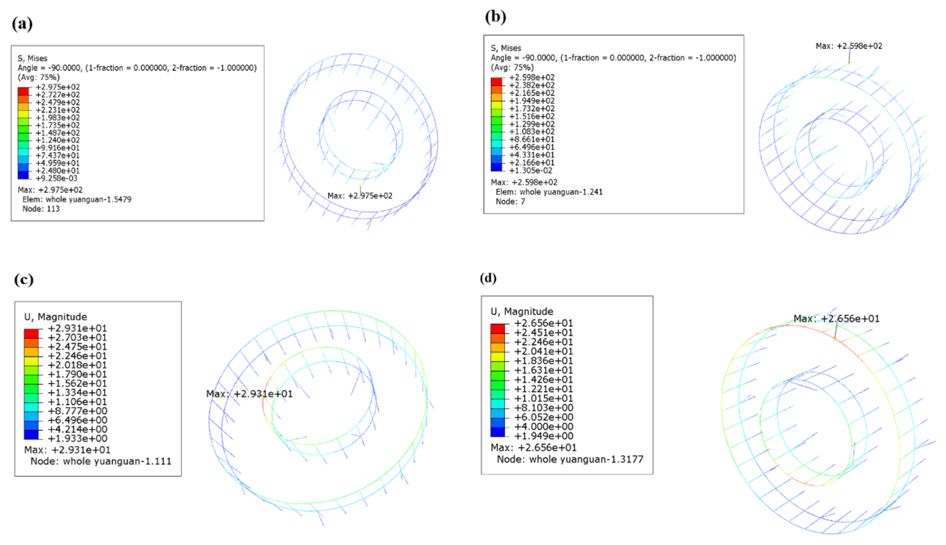
Figure 14Contour maps of stress and displacement for the pallet before and after optimization under the transportation conditions: (a) fence stress before optimization (unit: MPa), (b) fence stress after optimization (unit: MPa), (c) fence displacement before optimization (unit: mm), and (d) fence displacement after optimization (unit: mm).
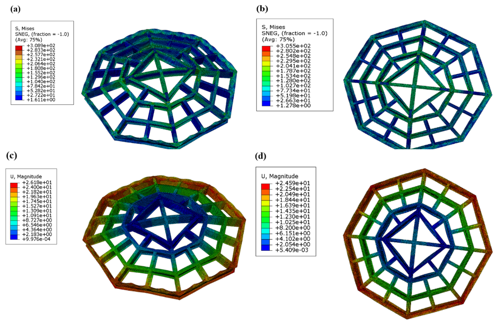
Figure 15Contour maps of stress and displacement for the pallet before and after optimization under the lifting conditions: (a) fence stress before optimization (unit: MPa), (b) fence stress after optimization (unit: MPa), (c) fence displacement before optimization (unit: mm), and (d) fence displacement after optimization (unit: mm).
The Kriging model is an interpolation method that defines its interpolated values as a linear combination of known sample responses. It exhibits high adaptability to nonlinear problems and has become one of the most widely used and representative surrogate models (Wang et al., 2017). Compared to the standard Kriging model, the universal Kriging model accounts for the spatial correlation of attribute values by introducing a variogram function, thereby producing interpolation results that are more consistent with real-world conditions (Montes and Ledo, 2010).
In this study, the universal Kriging model was employed to fit the sampled data. To ensure the validity of the optimization outcomes, it is essential to verify the model's predictive accuracy.
For the lifting and transportation conditions, the prediction accuracy of the universal Kriging model for each indicator, evaluated using the coefficient of determination (R2), is presented in Figs. 11 and 12, respectively.
As illustrated in the figures, the R2 values for the mass, stress, and displacement were all greater than 0.9. These results indicate that the surrogate model is highly reliable.
3.6 Optimization algorithm
The particle swarm optimization algorithm was originally proposed in 1995 (Eberhart and Kennedy, 1995), and its stability and convergence have since been rigorously proven. As a swarm intelligence evolutionary algorithm, PSO simulates the natural foraging behavior of bird flocks. In this model, the location of the food is analogous to the optimal solution of the problem, while the flight direction and spatial position of the birds correspond to the velocity and position of the particles, respectively. Through information exchange between the global optimum (gbest) and the individual historical optimum (pbest), the positions and velocities of the particles are continuously updated. Compared to standard PSO, multi-objective particle swarm optimization incorporates boundary handling mechanisms and constriction factors during particle velocity updates, thereby improving search efficiency. Furthermore, by introducing an external archive, superior solutions are preserved while inferior ones are discarded during each iteration of the optimization process. The velocity and position updating process is mathematically expressed as follows:
where Xi(t) is the position vector, Vi(t) is the velocity vector, pBest is the personal best position, gBest is the global best position, ω is the inertia weight factor, c1 and c2 are learning factors, and γ1 and γ2 are contraction factors.
In this study, the parameters were set as follows: the number of iterations was 200, the number of particles was 15, the inertia factor ω=0.9, the learning factors , and the contraction factors .
Based on the aforementioned principles, the submarine cable pellet structure was optimized using the multi-objective particle swarm optimization algorithm. Multiple sets of non-dominated solutions for the three performance indicators were obtained, and the resulting Pareto fronts are depicted in Fig. 13. The selected optimal solution is highlighted in red.
As can be observed, the three performance indicators – mass, displacement, and stress – exhibit clear trade-offs with one another. Based on the three-dimensional plot, the distribution of the objective values is both well-proportioned and convergent. These optimization results align closely with theoretical expectations. The final optimal design was determined by comprehensively evaluating both the multi-objective optimization results and the parameter sensitivity analysis. The optimization results of the pallet base and fence are illustrated in Tables 5 and 6.
The indicator results before and after optimization are compared in Table 7.
Following the optimization of the pallet base, its mass decreased from 26.2 to 24.8 t, and the displacement was reduced from 26.2 to 24.8 mm. Similarly, after optimizing the pallet fence, its mass decreased from 15.2 to 14.1 t, and the displacement dropped from 29.3 to 22.1 mm. Overall, a lightweight design was achieved for the pallet while its static stiffness was improved.
The contour maps of the structural stress and displacement obtained through finite-element analysis are shown in Figs. 14 and 15, respectively.
Table 8 compares the finite-element analysis results with the values predicted by the surrogate model. For the pallet base under the lifting condition, the errors in the maximum stress and maximum displacement were 4.16 % and 0.81 %, respectively. For the pallet fence under the transportation condition, the errors in the maximum stress and maximum displacement were 7.54 % and 16.9 %, respectively. These results demonstrate that the surrogate model possesses high accuracy and provides credible predictions.
In this study, the mechanical performance of a large submarine cable pallet was analyzed using finite-element analysis. Subsequently, the dimensional parameters of the pallet were optimized using a combination of the universal Kriging model and the multi-objective particle swarm optimization algorithm.
- (1)
A finite-element model of a large submarine cable pallet was established. Static analysis revealed that the strength of the pallet possessed a large safety margin. Therefore, it is feasible to reduce the mass of the pallet and further minimize its deformation through structural optimization.
- (2)
A total of 185 data sets for the pallet base design variables were generated using the design of experiment (DOE) method, and performance indicators, such as stress and displacement, were calculated via finite-element analysis (FEA). Among these, 55 data sets were utilized as the training set to establish the universal Kriging model. Similarly, 30 data sets for the pallet fence design variables were obtained via DOE, with their corresponding stresses and displacements calculated using FEA. All of these data sets were used to train another universal Kriging model. The average errors of the four groups data are 7.35 %.
- (3)
Under the lifting and transportation conditions, the influence of various pallet components on the performance indicators varied. Specifically, under the lifting condition, the flange had a more significant impact on the stress and displacement of the pallet base than the web. Similarly, the vertical fence exerted a greater influence on the stress and displacement than the transverse fence. The optimization objective was to minimize both the pallet mass and the displacement while satisfying the yield stress constraints. Following the optimization, the mass and displacement of the base were reduced by approximately 5.4 %, accompanied by a slight decrease in stress. Furthermore, the mass and displacement of the fence were reduced by approximately 7.2 % and 12.7 %, respectively.
The software code used for the current study is not publicly available as it is part of an ongoing research project, but it is available from the corresponding author upon reasonable request.
The datasets generated and analyzed during the current study are not publicly available because they are part of an ongoing research project and contain intermediate variables that are still being investigated. However, the data are available from the corresponding author upon reasonable request.
Conceptualization, YD and YL; methodology, YW and CZ; software, YW; validation, HZ and CL; formal analysis, LZ and YL; investigation, HZ; resources, HZ and CL; data curation, YZ and ZQ; writing – original draft preparation, YW; writing – review and editing, CZ and LZ; visualization, CL and ZQ; supervision, YL; project administration, HZ; funding acquisition, YD. All authors have read and agreed to the published version of the paper.
The contact author has declared that none of the authors has any competing interests.
Publisher's note: Copernicus Publications remains neutral with regard to jurisdictional claims made in the text, published maps, institutional affiliations, or any other geographical representation in this paper. The authors bear the ultimate responsibility for providing appropriate place names. Views expressed in the text are those of the authors and do not necessarily reflect the views of the publisher.
This research has been supported by the Graduate Research and Innovation Projects of Jiangsu Province (grant no. SJCX24_2090).
This paper was edited by Pengyuan Zhao and reviewed by two anonymous referees.
Abedin, J., Franklin, F., and Mahmud, S. M. I.: A Two-Stage Optimisation of Ship Hull Structure Combining Fractional Factorial Design Technique and NSGA-II Algorithm, Journal of Marine Science and Engineering, 12, 411, https://doi.org/10.3390/jmse12030411, 2024.
Cascino, A., Meli, E., and Rindi, A.: Multi-Stage Topology Optimization for Structural Redesign of Railway Motor Bogie Frames, Appl. Sci.-Basel, 16, 973, https://doi.org/10.3390/app16020973, 2026.
Eberhart, R. and Kennedy, J.: A new optimizer using particle swarm theory. MHS'95, Proceedings of the Sixth International Symposium on Micro Machine and Human Science, 39–43, https://doi.org/10.1109/mhs.1995.494215, 1995.
Jarcă, O. M. and Perijoc, D. S.: Comparative static FEA of equipment foundations on marine vessels: standard, stiffened, and structural integrated, Analele Universităţii “Dunărea de Jos” Din Galaţi Fascicula XI Construcţii Navale/Annals of “Dunărea de Jos” of Galati Fascicle XI Shipbuilding, 46, 125–132, https://doi.org/10.35219/annugalshipbuilding/2023.46.15, 2023.
Jiang, C., Yang, S., Nie, P., and Xiang, X.: Multi-objective structural profile optimization of ships based on improved Artificial Bee Colony Algorithm and structural component library, Ocean Eng., 283, 115124, https://doi.org/10.1016/j.oceaneng.2023.115124, 2023.
Kleijnen, J. P. C.: Design of Experiments: Overview, SSRN Electronic Journal, https://doi.org/10.2139/ssrn.1262179, 2008.
Kleijnen, J. P. C.: Regression and Kriging metamodels with their experimental designs in simulation: A review, Eur. J. Oper. Res., 256, 1–16, https://doi.org/10.1016/j.ejor.2016.06.041, 2017.
Luo, R. K., Gabbitas, B. L., and Brickle, B. V.: Dynamic stress analysis of an open-shaped railway bogie frame, Eng. Fail. Anal., 3, 53–64, https://doi.org/10.1016/1350-6307(96)00003-9, 1996.
Marjan, A. and Huang, L.: Topology optimisation of offshore wind turbine jacket foundation for fatigue life and mass reduction, Ocean Eng., 289, 116228, https://doi.org/10.1016/j.oceaneng.2023.116228, 2023.
Mathé, P.: Hilbert space analysis of Latin Hypercube Sampling, P. Am. Math. Soc., 129, 1477–1492, https://doi.org/10.1090/s0002-9939-00-05850-0, 2000.
Montes, F. and Ledo, A.: Incorporating environmental and geographical information in forest data analysis: a new fitting approach for universal kriging, Can. J. Forest Res., 40, 1852–1861, https://doi.org/10.1139/x10-131, 2010.
Na, S.-S. and Karr, D. G.: Development of Pareto strategy multi-objective function method for the optimum design of ship structures, Int. J. Nav. Arch. Ocean, 8, 602–614, https://doi.org/10.1016/j.ijnaoe.2016.06.001, 2016.
Nazemian, A. and Ghadimi, P.: Multi-objective optimization of trimaran sidehull arrangement via surrogate-based approach for reducing resistance and improving the seakeeping performance, P. I. Mech. Eng. M-J. Eng., 235, 944–956, https://doi.org/10.1177/1475090220980275, 2020.
Pehlivan Solak, H.: Multi-dimensional surrogate based aft form optimization of ships using high fidelity solvers, Brodogradnja, 71, 85–100, https://doi.org/10.21278/brod71106, 2020.
Rezvanipour, M., Kolios, A., Amirafshari, P., and Wang, L.: A reliability-constrained optimisation framework for offshore wind turbine support structures, International Journal of Sustainable Energy, 43, https://doi.org/10.1080/14786451.2024.2352786, 2024.
Romero-Tello, P., Lorente-López, A. J., and Gutiérrez-Romero, J. E.: Structural design optimization of pressure hull using genetic algorithm and finite element analysis, International Journal of Structural Integrity, 16, 60–84, https://doi.org/10.1108/ijsi-10-2024-0171, 2025.
Serani, A., Scholcz, T., and Vanzi, V.: A Scoping Review on Simulation-based Design Optimization in Marine Engineering: Trends, Best Practices, and Gaps, arXiv, https://doi.org/10.48550/arxiv.2404.18654, 2024.
Tian, X., Sun, X., Liu, G., Deng, W., Wang, H., Li, Z., and Li, D.: Optimization design of the jacket support structure for offshore wind turbine using topology optimization method, Ocean Eng., 243, 110084, https://doi.org/10.1016/j.oceaneng.2021.110084, 2022.
Wang, J. T., Wang, C. J., and Zhao, J. P.: Frequency response function-based model updating using Kriging model, Mech. Syst. Signal Pr., 87, 218–228, https://doi.org/10.1016/j.ymssp.2016.10.023, 2017.
Wu, Z., Gong, J., Ding, J., Sun, Y., and Ma, C.: Autonomous modification and optimization method for rim-driven system in surface ships, Ocean Eng., 290, 116293, https://doi.org/10.1016/j.oceaneng.2023.116293, 2023.
Xiao, S., Zhang, H., Wei, Y., Shen, Q., and Zhao, Z.: Analysis of the overall structural strength and optimization recommendations for ultra-large container ships based on the improved equivalent design wave method, Mech. Adv. Mater. Struc., 1–11, https://doi.org/10.1080/15376494.2024.2400239, 2024.
Ye, N., Long, T., Meng, J., Shi, R., and Zhang, B.: Surrogate-assisted optimization for anti-ship missile body configuration considering high-velocity water touching, Chinese J. Aeronaut., 36, 268–281, https://doi.org/10.1016/j.cja.2023.07.010, 2023.
Yu, C., Lv, X., Huang, D., and Jiang, D.: Reliability-based design optimization of offshore wind turbine support structures using RBF surrogate model, Frontiers of Structural and Civil Engineering, 17, 1086–1099, https://doi.org/10.1007/s11709-023-0976-8, 2023.