the Creative Commons Attribution 4.0 License.
the Creative Commons Attribution 4.0 License.
 | 03 Feb 2026
Modeling and experimental study of cutting forces in pulsed laser-assisted cutting of SiCp ∕ Al considering temperature effects
Tiange Han
Anping Xiong
Xiaoqin Zhou
Shuaijie Zhai
Ming Wang
Zhun Qiao
composite is a kind of metal matrix composite with aluminum alloy as a matrix and silicon carbide particles as reinforcement, which shows a broad application prospect in the aerospace and automotive industries by virtue of its excellent mechanical properties and lightweight characteristics. However, its non-uniform reinforcing phase distribution and the difference in the properties of the two phases lead to the problem of high cutting force during the machining process. In this study, based on a three-dimensional transient temperature field simulation model considering the equivalent thermophysical properties of the Al matrix and SiC particles, a cutting force decomposition model for the pulsed laser-assisted cutting of composites is established, and the accuracy of the cutting force model is verified by the pulsed laser-assisted cutting test. The obtained cutting force modeling equations show that the cutting speed, feed, depth of cut, and cutting temperature all affect the magnitude of the cutting force. The results of the cutting tests show that the overall error between the magnitude of the main cutting force, predicted by the cutting force model and the measured values of the tests, is within 20 %, which proves the reliability of the cutting force model.
- Article
(2689 KB) - Full-text XML
- BibTeX
- EndNote


composites, as an emerging particle-reinforced metal matrix composite material, are increasingly emerging in many industrial and engineering applications, replacing traditional material choices due to their high hardness, low coefficient of thermal expansion, and wear-resistant properties (Yuan et al., 2023). However, the Al matrix and SiC particles have very different mechanical properties and material property differences, which makes conventional processing very difficult (Zhou et al., 2014).
Laser-heating-assisted cutting technology focuses a high-energy pulsed laser on the cutting zone instantaneously, causing the material to rapidly warm up and soften before machining. The technology utilizes the thermoplastic effect to reduce the yield strength of the material, reducing cutting forces and tool wear, while suppressing machining chatter, ultimately realizing high-quality machining with high efficiency and low consumption (You et al., 2020; Gao et al., 2025). Rashid et al. (2014) conducted a precision laser-assisted cutting orthogonal experiment on β titanium alloy. It was found that if the material is preheated to 1050–1250 °C, the cutting force can be reduced. Dandekar and Shin (2013) carried out laser-assisted cutting experiments on 20 % composites in order to analyze the optimization of the cutting force due to the variation of the laser heating temperature. The experimental data illustrated that the laser heating condition of 300 °C presented the best performance, and the cutting force was reduced by 12 % under this condition. In the process of laser-assisted milling, Feng et al. (2019) found that the influence of preheating temperature and processing temperature is incorporated into the established temperature prediction model. The model can accurately estimate the temperature change in the processing area by integrating the influence of shear heat source and friction heat source. In order to confirm the reliability of the temperature prediction model, laser-assisted milling experiments are carried out on Si3N4 and . The experimental results show that the error between the actual temperature measurement value and the predicted value of the model is very small, which proves the validity of the temperature model.
Jiao et al. (2016) analyzed the wear mechanism of the PCBN tool under the combined action of laser and ultrasonic vibration in order to study the wear mechanism of the PCBN tool and its influence on the cutting process. It was found that laser heating and two-dimensional ultrasonic combined with auxiliary cutting can effectively relieve tool wear, improve dimensional accuracy and surface quality, and reduce cutting force. Abedinzadeh et al. (2022) conducted experiments on Al-1 wt % SiC-1 wt % Al2O3 hybrid nanocomposite material samples and assisted turning experiments with pulsed Nd : YAG lasers. The experimental results show that pulsed Nd : YAG lasers can achieve the uniformity of temperature distribution in the cutting process, so as to form an ideal heat-affected zone, which is helpful to improve the machining consistency.
Cutting force models are constructed in cutting experimental investigations and form the theoretical cornerstone of experimental planning and parameter optimization (Pramanik et al., 2006; Bian et al., 2012). Yin et al. (2021) developed a new model of orthogonal cutting force for composites, taking into account the particle volume fraction, size, random distribution of aspect ratio, and dynamic thermal effects. It is shown that the bi-directional average cutting force (Fc/Ft) tends to increase when the volume fraction is increased from 15 % to 65 % or the particle size is increased from 5 to 60 µm; the cutting force is stabilized when the aspect ratio is >6 or <2, and then it decreases linearly with the increase in aspect ratio in the range of 2–6. Sikder and Kishawy (2012) constructed a new cutting force analysis model and established a framework for the calculation of chip-forming force, based on orthogonal cutting mechanics and the Johnson–Cook intrinsic model. This combines the slip line field theory and the Griffith's failure theory in solving the plowing force and the particle fracture force, and establishes a framework of multi-mechanics coupling analysis for the prediction of the cutting force of metal matrix composite materials. Lin et al. (2022) developed a new cutting force model, which integrates the transient depth of cut/shear angle effect and decomposes the total cutting force into four components: chip generation force, tool-chip friction, particle fracture, and ultrasonic impact. The accurate prediction of the main cutting force is realized through multi-force coupling analysis, and the deviation between experiment and simulation is <13 %, which verifies the high reliability of the mode. Zhang et al. (2022) accurately predicted the cutting force and surface morphology based on the three-phase cutting model and studied the interaction between the tool and the matrix phase, the particle enhancement phase, and the interface phase in the cutting process. Du et al. (2023) established a multiphase simulation model that integrates three-phase relationships and random particle distribution. They investigated the dynamic effects of chip formation and cutting forces on composite materials and found that ultrasonic elliptical vibration-assisted cutting results in more continuous sawtooth-shaped chips in SiCp/Al composites, making SiC particles easier to break and improving the machinability of SiCp/Al composites. The material generates more continuous sawtooth, which makes SiC particles easier to break and improves the machining performance of composite materials. Under the cutting depth of 25 and 50 µm, the cutting force decreases 26 % and 23 % respectively, and the surface roughness decreases 19 % and 28 %, respectively.
In summary, in this study, pulsed laser-assisted cutting composites start with the different material properties of SiC particles and the Al matrix, along with the heating and softening effect of the pulsed laser on the workpiece. Based on the heat conduction theory, a three-dimensional transient temperature field model considering the equivalent thermal properties of Al matrix and SiC particles is established. At the same time, the finite element simulation and cutting test are carried out by ABAQUS software to verify the validity of the model.
2.1 Temperature field modeling construction
Based on the theory related to heat conduction, the three-dimensional transient heat conduction equation is first considered, including the laser heat source term (Abedinzadeh et al., 2022; Ma et al., 2020):
where T represents the temperature field, ρ represents the material density, cp represents the material specific heat capacity, k represents the thermal conductivity, and Q represents the laser heat source term.
The laser heat source term Q contains a spatial Gaussian distribution and temporal pulse characteristics:
where α represents the material absorption rate of the laser, P0 represents the laser power, r0 represents the laser spot radius, and fpulse(t) represents the time pulse function.
The time pulse function follows a rectangular pulse sequence:
Tp stands for the pulse period, τ represents the single pulse width, and rect(u) stands for the pulsed laser function.
Set the initial temperature condition to room temperature:
Boundary conditions are set up with the pulsed laser acting on the material surface, considering thermal convection and radiative heat dissipation:
where h is for the convective heat transfer coefficient, ε represents the material emissivity, and σ is the Stefan-Boltzmann constant.
Other surfaces are adiabatic, assuming that heat is conducted primarily in the depth direction, i.e., the normal phase gradient is zero:
For composites, the thermophysical properties of the Al matrix and the SiC particles are significantly different and need to be defined separately. The composite is considered as a homogeneous medium during the calculations, and the equivalent thermophysical parameters are derived by the mixing law:
VSiC is the volume fraction of SiC particles: 45 %. This equivalent thermophysical property model based on the mixing law can effectively solve the problem of discontinuity of the thermal parameters of the two-phase materials in the temperature field modeling process.
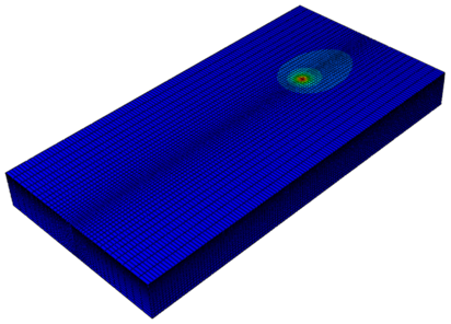
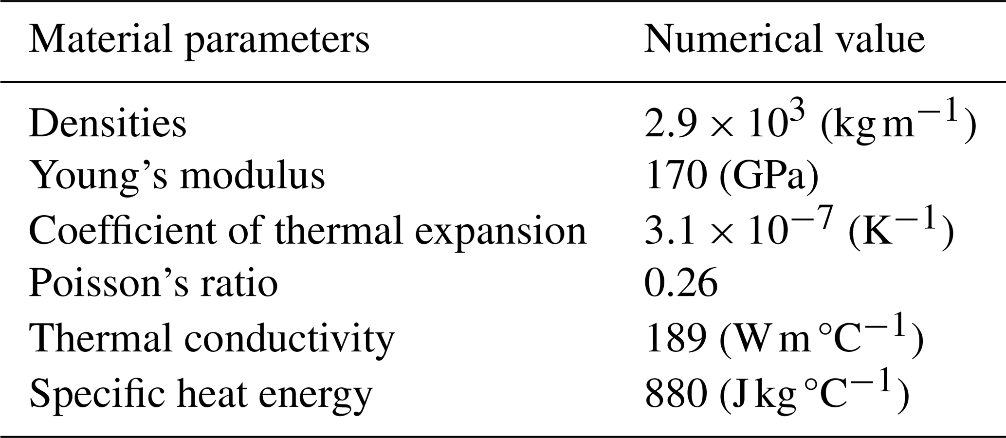
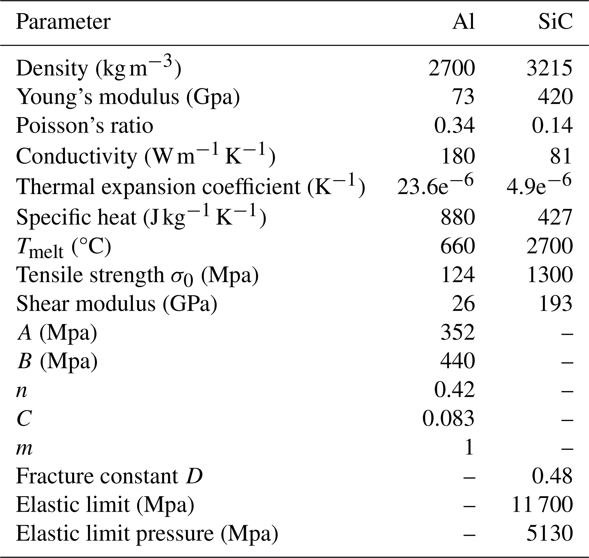
The unfolded three-dimensional material model established using ABAQUS finite element software is shown in Fig. 1. In the meshing of the material model, the mesh of the laser irradiation region is refined to improve the accuracy of the simulation results; and the meshes of the other regions and the laser irradiation region are set up with transition regions and appropriately coarsened to simplify the model, reduce the number of calculations, and improve the efficiency of the calculations. The pulse form is regarded as a rectangular pulse, and the pulse width is set to 100 ns (the time of a single pulse of the laser acting on the workpiece). The material property parameters are set, as shown in Table 1 (Sun et al., 2021).
2.2 Temperature field simulation analysis
When a pulsed laser irradiates composites, the magnitude of the laser power directly affects the heating efficiency, which in turn affects the temperature rise of the material. In order to analyze the influence of different laser powers on the material surface temperature field, the laser power is set to 8, 13, 18, and 23 W using the VDFLUX subroutine associated with ABAQUS, and four groups of simulations are carried out to control and analyze the distribution of the surface temperature field of the material under the conditions of different laser powers. The cloud diagram of the simulation results is shown in Fig. 2.
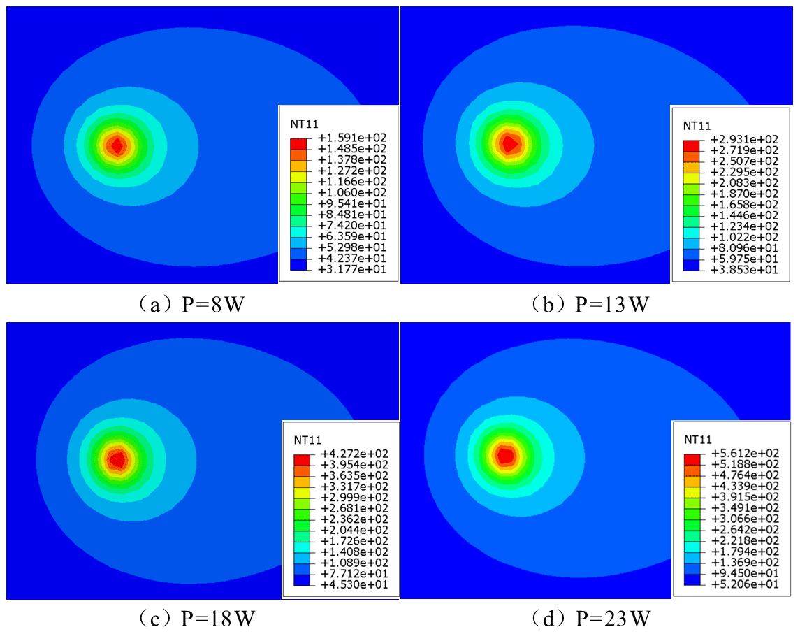
Figure 2Distribution of the material surface temperature field under different laser powers.
The temperature at the center of the light plate increases from 159.1 °C, when the laser power is 8 W, to 561.2 °C), when the laser power is 23 W. The dynamic temperature field is ovoid, with a higher residual temperature in the rear than in the unirradiated region and a steeper gradient at the leading edge. The power enhancement resulted in a non-linear increase in the rate of temperature increase, confirming the excellent thermal response of the composites to the pulsed laser. The melting point of the Al matrix is around 660 °C. The temperature of the Al matrix is around 660 °C (Wei et al., 2020). When the laser power is 8 W, the maximum temperature of the material surface is 134.4 °C. At this time, the temperature is low, and the pulsed laser cannot play a good softening effect on the material, which does not reach the optimal situation of pulsed laser-assisted cutting. When the laser power is 23 W and the maximum temperature of the material surface is 561.2 °C, the temperature is too high, although not more than the melting point of the Al matrix. The cutting process will produce a lot of cutting heat, resulting in the ablation of the material surface, contrary to the original intention of the pulsed laser-assisted cutting (Min and Choon, 2016). The advantages of pulsed laser-assisted cutting can only be realized when the surface temperature of the material is optimal, which is roughly controlled at 200–500 °C, and the appropriate laser power should be selected during processing.
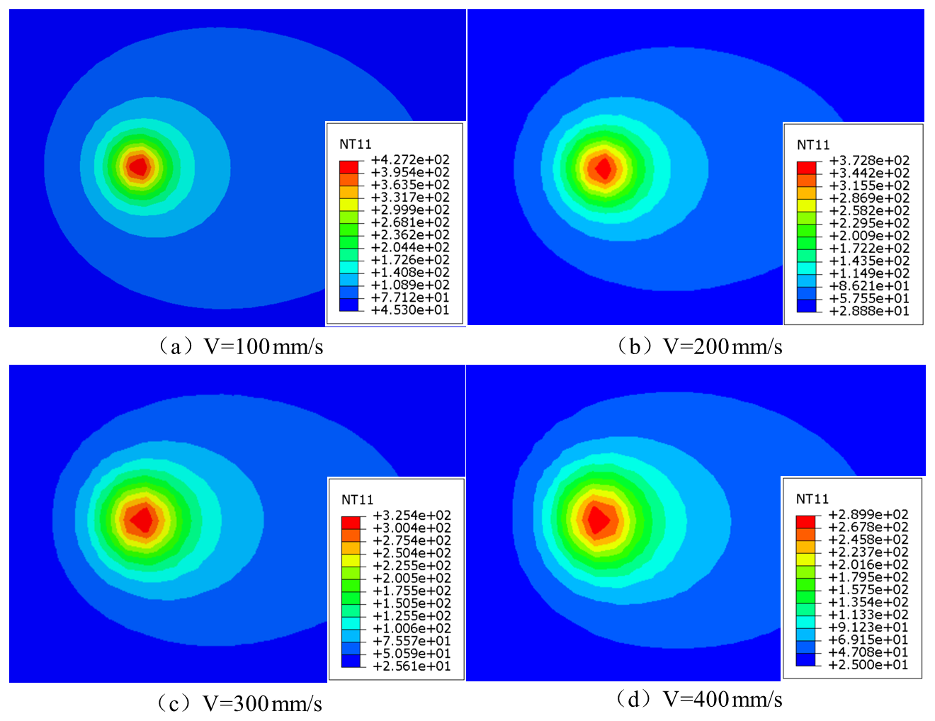
Figure 3Distribution of the material surface temperature field at different laser travel speeds.
To investigate the influence mechanism of the laser scanning rate change on the thermal distribution characteristics of the material surface layer, the laser moving speed is set to 100, 200, 300, and 400 mm s−1 using the VDFLUX subroutine associated with ABAQUS. The distribution of material surface temperature field under different laser spot radii was then analyzed. The cloud diagram of the simulation results is shown in Fig. 3. Simulations show that the laser travel speed increases from 100 to 400 mm s−1 and leads to a decrease in the material surface temperature from 427.2 to 289.9 °C (Δ137.3 °C) when other laser parameters are constant. This thermal decay effect results from the shortening of the thermal accumulation time due to the speed increase, leading to an enhanced diffusion of the energy density. Process optimization requires controlling the travel speed in the range of 100–300 mm s−1 to maintain the surface temperature in the 200–500 °C thermoplastic window. Matching the cutting speed to achieve the optimal thermal coupling ensures that the material softens sufficiently, without thermal damage.
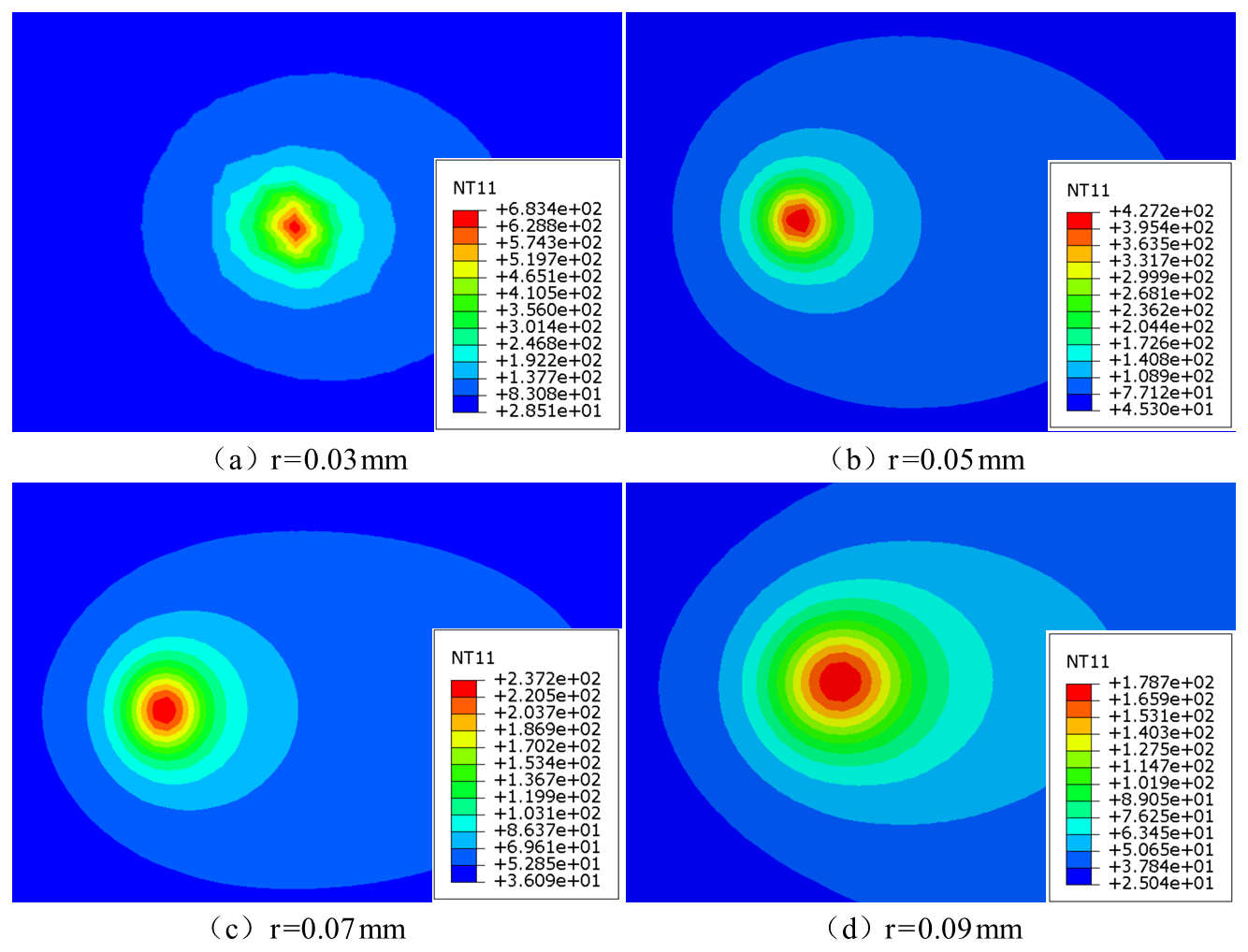
Figure 4Distribution of the material surface temperature field at different laser spot radii.
To explore the influence law of laser radius change on the thermal distribution characteristics of the material surface layer, the laser spot radius is set to 0.03, 0.05, 0.07, and 0.09 mm using the VDFLUX subroutine associated with ABAQUS. Four sets of simulation controls are carried out to analyze the distribution of the material surface temperature field under different laser spot radius conditions. The cloud diagram of the simulation results is shown in Fig. 4.
Simulation shows that the spot radius is non-linearly correlated with the material temperature: 683.4 °C at 0.03 mm, exceeding the melting point of Al at 660 °C (triggering ablation) and 178.7 °C at 0.09 mm, which is insufficient softening. The mechanism analysis shows that the process optimization needs to control the spot radius in the range of 0.05–0.07 mm, so that the surface temperature is stable in the thermoplastic window of 200–500 °C. This not only avoids the occurrence of ablation but also ensures the full softening and achieves the optimal balance of the cutting process.
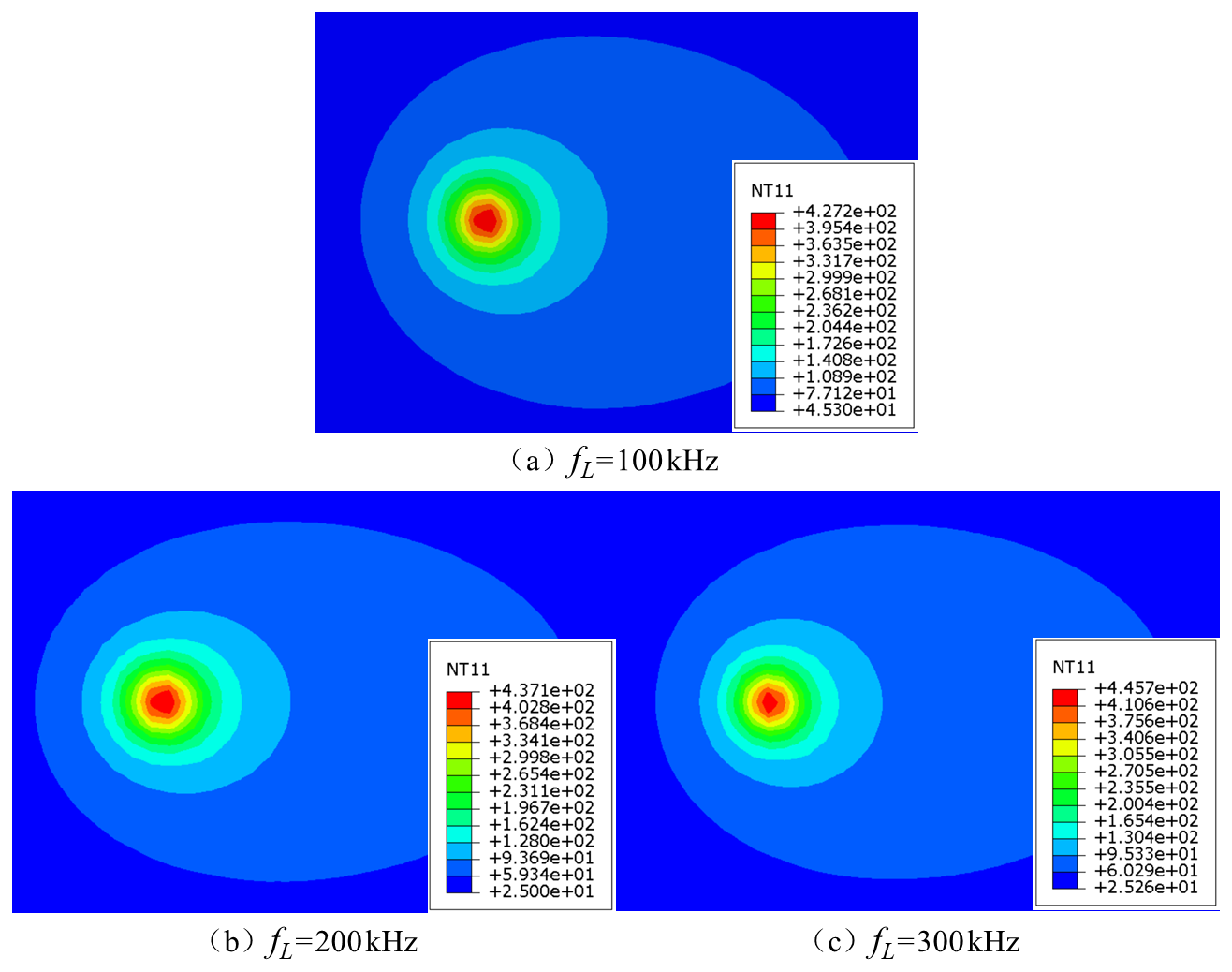
Figure 5Distribution of the material surface temperature field at different laser pulse frequencies.
To explore the influence mechanism of the laser pulse frequency variable on the thermal distribution characteristics of the material surface layer, the solid uses the VDFLUX subroutine associated with ABAQUS to set the laser pulse frequency to 100, 200, and 300 kHz, respectively. Three sets of simulation control experiments are conducted in order to analyze the distribution of the surface temperature field of the material under the conditions of different laser pulse frequencies. The cloud diagram of the simulation results is shown in Fig. 5.
Simulations show that the surface temperature increases slightly from 427.2 to 445.7 °C (Δ18.5 °C) when the pulse frequency 100 kHz rises to 300 kHz, and the thermal accumulation effect is governed by the balance between the pulse energy ) and the total energy (Przestacki, 2014; Przestacki et al., 2016). Compared to power, speed, and radius parameters, frequency modulation has a weaker effect on temperature (<5 % increase), which needs to be combined with multi-parameter co-optimization of the process.
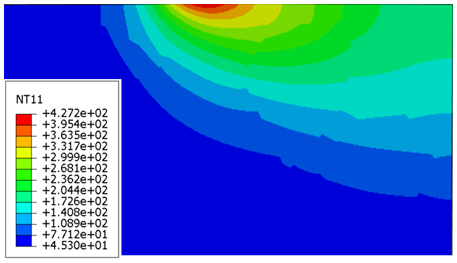
In summary, the laser parameters that can achieve the best cutting conditions are laser power 18 W, laser travel speed 100 mm s−1, laser radius 0.05 mm, pulse frequency 100 kHz, and pulse width 100 ns. Figure 6 shows the distribution of the temperature field in the direction of cutting depth to meet this condition. The bending of isotherms in the figure is due to the presence of SiC particles in the material and the thermal conductivity of the Al matrix. The large gap between the SiC particles and the Al matrix leads to an uneven temperature distribution. The temperature field distribution in the cutting depth direction provides a theoretical basis for the establishment of the cutting force model of composites with the subsequent pulse laser-heating-assisted cutting.
3.1 Modeling of particle–substrate interfacial forces
During the pulsed laser-assisted cutting of composites, SiC particles make contact with the Al matrix and induce fragmentation and fracture phenomena under the action of tool pressure (Zhang et al., 2019), which is called the particle–matrix interface force.
The particle–substrate interfacial force Fi1 for a single SiC particle is first found from the energy of destruction of the individual SiC particle Q and is expressed as
where Kc represents the fracture toughness of SiC particles 3 MPa m½, a represents the initial crack length of SiC particles, w represents the initial crack width of SiC particles 1 µm, v1 represents the Poisson's ratio of SiC particles, and E1 represents the elastic modulus of SiC particles.
The percentage of SiC particles that undergo damage during cutting is approximately equal to the volume fraction of SiC particles in the composite, and the number Ns of SiC particles that undergo damage is approximately
P represents the probability of destruction of SiC particles during the cutting process, which is about
where σP represents the maximum tensile stress of SiC particles, S represents the percentage of SiC particles, and g represents the shape parameter of SiC particles.
Then the total particle–substrate interfacial force Fi of SiC particles is
The total particle–substrate interfacial force Fi of SiC particles is decomposed into a force Fip in the direction of cutting speed and a force Fit in the direction of cutting depth:
δh represents the angle between the direction of the combined individual particle–substrate interfacial force and the direction of the cutting speed, which can be expressed as
3.2 Shear force modeling
During the cutting process, the shear deformation occurring in the composite and the homogeneous material is approximately the same, so in order to simplify the model, the SiC particles are neglected for the modeling of shear (Jin et al., 2022). Figure 7 shows the force in the shear deformation region of composites.
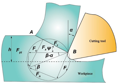
Based on Merchant's theory, it is known that the forces of the tool and of the workpiece in the shear zone are a pair of interacting forces. The force Fc along the cutting direction of the tool is
Force in the direction of the depth of cut is
In the two equations, ka represents the Al matrix shear strength; h represents the cutting thickness, f represents the feed, β represents the friction angle, α represents the tool front angle, and φ represents the shear angle.
The composite cutting process has the presence of tool tip arcs, as shown in Fig. 8. Involved in the cutting edge rz and straight-line DB, the combination of the two can be approximated as a straight line DC. This line is called the equivalent cutting edge. When the depth of cut is greater than the radius of the tip circle, the equivalent main deflection angle ks is
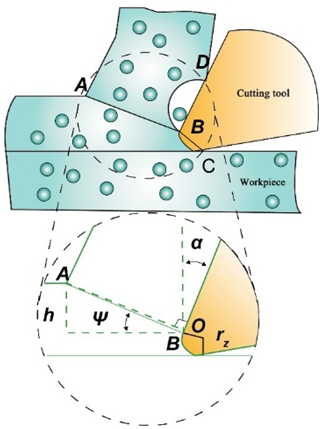
When the depth of cut is less than the radius of the blade arc, the equivalent main deflection angle ks is
Shear force on the shear plane AB:
where τs represents the shear flow stress, rz represents the radius of the cutting edge circle, and d represents the cutting width in the direction of the cutting edge.
The magnitude of the shear flow stress τs can be determined from the Johnson–Cook intrinsic model, which is typically capable of providing a quasi-dynamic and dynamically strained environment for the flow stresses in materials under a high degree of strain, strain rate, and temperature fluctuations. Since the composites were considered as homogeneous Al metallic materials, the parameters of the intrinsic model of the Al matrix are shown in Table 2. However, SiC particles, as brittle and hard materials, are specially introduced into the JH-2 constitutive model, as shown in Table 3, to characterize their physical properties (Wang et al., 2018).
Table 2Parameters of J–C intrinsic model for Al matrix (Johnson and Cook, 1985).
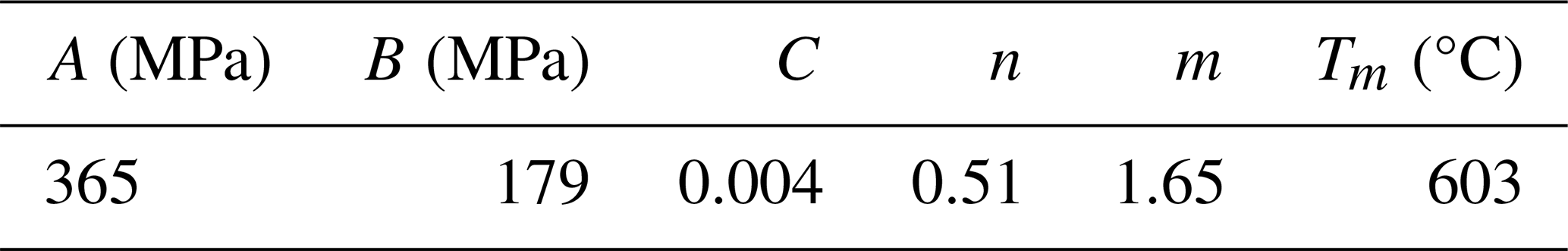
Table 3Mechanical properties and finite element model parameters of .
Then the shear flow stress τs
where A represents the yield stress of the material, B represents the hardening modulus of the material, C represents the strain rate hardening coefficient of the material, n represents the strain-hardening index of the material, m represents the temperature softening index of the material, represents the reference strain rate of the material 1 s−1, and ε represents the equivalent plastic strain of the material. This can be obtained by the following formula:
Here, represents the equivalent plastic strain rate of the material and can be obtained from the following equation:
where T0 represents the initial temperature of the shear surface, T1 represents the ambient temperature, and T2 represents the melting point of the material.
In the JH-2 constitutive model, the equivalent stress of SiC particles can be expressed as
The initial temperature of the shear surface T0 is
where Ta represents the laser irradiation temperature at the shear surface, τ0 represents the initial shear stress, ρ represents the density of the material, and Ct represents the specific heat capacity of the material.
In the pulsed laser-assisted cutting process, the laser irradiation in front of the tool heats the material to soften it. To simplify the calculation, the laser irradiation temperature at the cutting surface is approximated to be the average of the highest temperature in the heat-affected zone of the pulsed laser heating-temperature field in Fig. 6 and the depth of cut (Wu et al., 2021).
3.3 Friction modeling
The friction between the tool and the material is mainly divided into the friction between the front face of the tool and the chip, and the friction formed by the contact between the back face of the tool and the material surface.
During the cutting process, the sliding of chips on the tool surface consumes a certain amount of energy in resisting the friction on the front face of the tool. In order to construct an accurate cutting force prediction model, the friction between the tool and the chip cannot be neglected. As SiC particles are contained in composites, the pulsed laser irradiation of the material softens the material sufficiently, causing the tool to pull out the SiC particles during the cutting process and follow the tool along with the cutting (Li et al., 2020). SiC particles and the front tool surface are divided into two forms, namely the two-body sliding friction and the three-body rolling friction, as shown in Fig. 9. Therefore the tool–chip friction should be divided into the friction between the Al matrix and the front tool face, and the friction between the SiC particles and the front tool face.
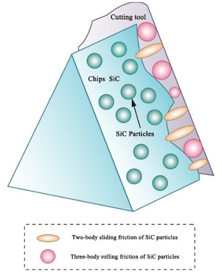
The interaction between the front face of the tool and the SiC particles within the chip creates a two-body sliding friction phenomenon, and this process is accompanied by sliding the chip along the front face of the tool. On the other hand, three-body rolling friction occurs during the cutting process when the tool pulls the SiC particles out of the matrix, and these particles generate rolling at the contact interface between the tool and the newly generated chip. Therefore, the total friction between the tool and the SiC particles can be derived by combining the effects of these two friction modes:
Two-body sliding friction is analogous to abrasive friction and can be expressed as
where Ht represents the hardness of the tool, which depends on the material of the tool itself; q represents the proportion of SiC particles that undergo two-body sliding friction, which is related to the size of the particles; and Ap represents the contact area of individual particles with the front face of the tool. The specific case is shown in Fig. 10 and is taken to be approximately the product of the equivalent width of cut and the equivalent depth of cut:
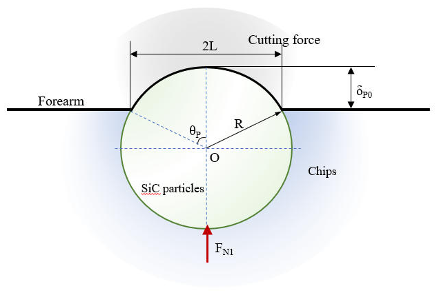
The top angle θp can be expressed as
δp0 represents the critical penetration depth of the front blade surface of the SiC particle extrusion tool, which is affected by the heat generated by laser irradiation and friction, and its value can be expressed as
E∗ represents the composite modulus GPa, which can be expressed by the following equation:
where E1 represents the modulus of elasticity of SiC particles, E2 represents the modulus of elasticity of the tool, V1 represents the Poisson's ratio of SiC particles, and V2 represents the Poisson's ratio of the tool.
In Eq. (28), Np represents the number of SiC particles that undergo two-body sliding friction:
where Vp represents the volume fraction of SiC particles, As represents the contact area between the tool and chip, and R represents the radius of SiC particles.
The three-body rolling friction can be defined as the product of the three-body rolling friction coefficient and the normal force exerted at the interface between the front surface of the tool and the SiC particles in contact:
μ3b represents the three-body rolling friction coefficient and can be expressed as
The normal force at the interface between the front face of the tool and the SiC particles can be expressed as
where P1 represents the probability of the pull-out fracture of SiC particles, which is related to the size of the particles (Kishawy et al., 2004); and Fn1 represents the normal force on a single SiC particle. This can be expressed as
The hardness of the Al matrix is relatively low compared to the SiC particles and the tool, so it is prone to softening under the influence of the laser temperature and cutting temperature. In order to simplify the calculation, the friction between the Al matrix and the front face of the cutter can be approximately regarded as the friction between the cutter and the homogeneous Al metal, and the normal force at the interface of the front face of the cutter and the Al matrix can be ignored (Nima et al., 2020). The friction between the Al substrate and the front blade surface can be expressed as
τc represents the average shear stress between the Al matrix and the front face of the tool, and the Al matrix is isotropic and viscoplastic (Waldorf, 1996). It can then be calculated by the intrinsic Eq. (23), and since the heat generated by the pulsed laser irradiation on the material surface is much larger than the heat generated by the friction between the Al substrate and the tool's front face, the temperature of the Al substrate–tool interface can be regarded as the temperature of the plane where the depth of cut is located in the heat-affected zone in Fig. 6; σAl represents the ultimate tensile strength of the Al matrix; and AAl represents the contact area between the Al matrix and the front face of the tool, which can be expressed as
Aq indicates the contact area between the chip as a whole and the front face of the tool.
From the above analysis, the total friction between the front face of the tool and the chip is
Decompose the total friction force into forces along the cutting direction and the depth of cut.
Since this model ignores the normal force at the interface between the front face of the tool and the Al matrix, the total normal force on the front face of the tool is the normal force at the interface between the front face of the tool and the SiC particles. The ratio of the total friction force Ff to the total normal force FN on the front face of the tool gives the friction angle β:
During the cutting process, the thermomechanical load at the interface between the tool and the workpiece will be affected by the SiC particles, leading to the formation of tool wear. In order to accurately predict the cutting force model, the friction formed by the contact between the tool's back face and the material surface cannot be neglected, as shown in Fig. 11.
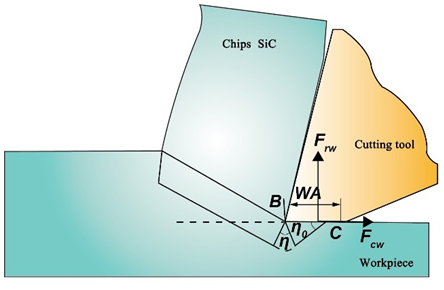
The normal force and friction on the back tool face can be expressed as
where WA represents the width of the wear zone, where a critical wear zone WA∗ is formed due to the high material temperature caused by the pulsed laser irradiation; and σw and τw represent rear blade surface stresses.
WA :
where
Here, ηw represents the field angle of the friction slip line at the rear blade surface and mw represents the coefficient of friction at the blade edge.
:
Here, η0 represents the slip line field angle of the material in the wear zone when friction is steadily building up, which is approximately equal to the friction slip line field angle of the backface ηw; mp represents the coefficient of friction at the cutting edge at this point in time, which is approximately equal to mw; ρ0 represents the first angle, which is approximately 0 when the ratio of the thickness of the uncut chip to the width of the cut is greater than 0.05; and τs represents the shear flow stress in the shear zone of the back tool face, which can be calculated by the intrinsic Eq. (23). Since a large part of the heat generated by the pulsed laser irradiation of the material surface flows into the chip, and a small part flows into the surface that is in contact with the back face of the tool, the temperature can be approximated to be considered as the lowest temperature of the plane at which the depth of cut is located, indicated in Fig. 6.
3.4 Lateral compression force modeling
Due to the existence of the tip radius of the tool, the cutting process will make part of the workpiece material squeezed into the cutting edge below, generating lateral squeezing pressure. According to the slip line field model equation (Waldorf, 2006), the lateral compression force is decomposed into a radial force Fp along the center of the cutting edge and a tangential force Ft along the center of the cutting edge:
According to the above equation, the lateral squeezing force is then decomposed into a force Fwp in the direction of cutting speed and a force Fwt in the direction of cutting depth:
In summary, the cutting force of pulsed laser-assisted cutting of composites can be expressed as the force FV in the direction of cutting speed and the force FD in the direction of cutting depth:
4.1 Test platform construction
The pulsed laser-assisted cutting experimental system mainly consists of three parts: cutting system, pulsed laser heating system, and cutting force measurement system, as shown in Fig. 12.
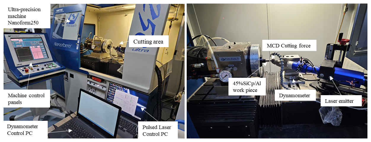
The cutting system consists of a three-axis ultra-precision diamond processing machine Nanoform 250, MCD single-crystal diamond tools, and workpieces. The three-axis ultra-precision diamond processing machine Nanoform 250 has an X and Z guideway travel of 220 mm, a standard rotary diameter of 250 mm, a motion accuracy of less than 15 nm, and a maximum spindle speed of 7000 rpm. The pulsed laser heating system is mainly composed of a pulsed laser transmitter, a pulsed laser control PC, and an infrared thermal imaging camera. This test uses an IPG Nanosecond Pulsed Laser (model YLPN-1-100×500-10), with a power adjustment range of 0–100 W, a pulse frequency adjustment range of 100–600 kHz, and a pulse width adjustment range of 100–500 ns. The radius of the emitted laser spot is 0.05 mm. In this test, a FAST M200 infrared camera from TELOPS Canada was used to measure the cutting temperature during pulsed laser-assisted cutting, with a cooled mercury cadmium telluride (HgCdTe) detector, a temperature range of 0–2500 °C, and a precision of 1 °C. The camera was mounted at the rear of the machine to provide a more accurate measurement of the temperature of the tool. Due to the space constraints inside the machine, the rear side of the machine was chosen as the location for the camera. To achieve more accurate results, the camera should be aligned with the front face of the tool, and the lens should be as close to the tool as possible. A pulsed laser angle of incidence that is too large may lead to the uneven distribution of energy density, which in turn reduces the rate of temperature rise of the workpiece and negatively affects the softening process of the material. Therefore it is necessary to appropriately limit the size of the angle of incidence. The laser angle of incidence of 60° was selected for this test. The cutting force measurement system includes a force gauge, charge amplifier, data acquisition system, and control PC. The whole experimental platform for pulsed laser-assisted cutting of is shown in Fig. 12.
4.2 Analysis of test results
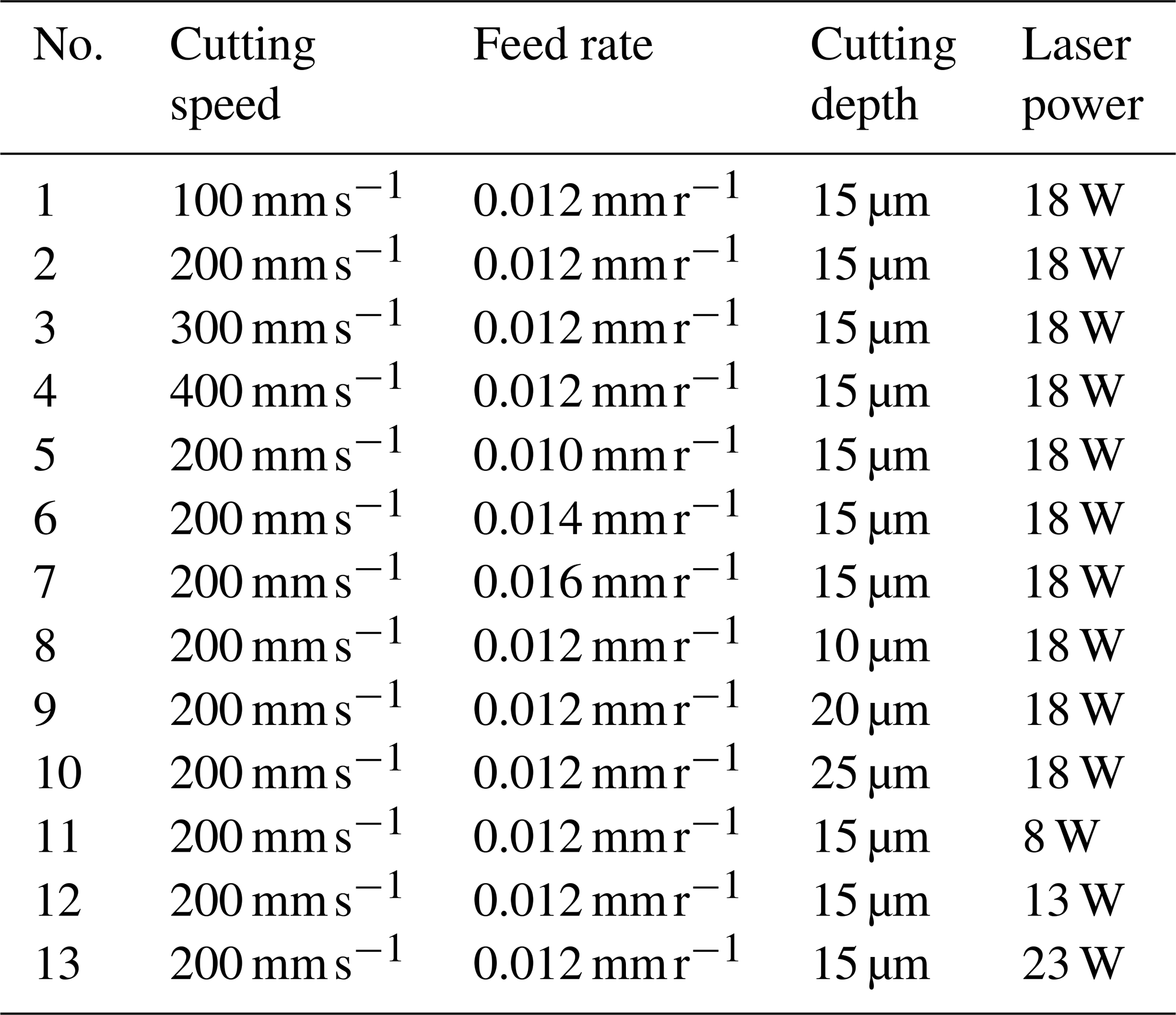
Analysis of the derived cutting force model formula shows that the key elements of cutting force mainly include cutting speed, feed, depth of cut, and cutting temperature. It is worth noting that the cutting temperature is not an independent factor; it is subject to the heating effect of the pulsed laser on the material as well as the double effect of the heat generated in the cutting process. Therefore, infrared thermography technology was used to measure the cutting temperature during the experiment. The laser spot radius was fixed at 0.05 mm, the pulse frequency was fixed at 100 kHz, and the pulse width was fixed at 100 ns. The rest of the experimental parameters were set as shown in Table 4.
Table 4Validation test parameters of the cutting force model .
The main cutting force is an important factor causing tool vibration and workpiece damage during the cutting process, and the direction is the same as the direction of the cutting speed, which is the component of the cutting force on the cutting speed. During the cutting test, the average value is taken after each group of tests is repeated three times. The surface temperature of the workpiece cut by the pulsed laser-assisted cutting of the composite material is shown in Table 5, and the main cutting force test results and comparison are shown in Fig. 13 and Table 6. The measured values and errors of the serial numbers in the table correspond to the results under the experimental parameters of each serial number in Table 4.
Table 5Surface temperatures of the workpiece by pulse laser-assisted cutting.
Table 6Test results of the pulsed laser-assisted cutting of the composites main cutting force.
Figure 13Comparison of predicted and measured values of the main cutting force with different cutting parameters.
When the cutting speed is in the interval of 100–400 mm s−1, the error between the measured and predicted values of the main cutting force is 4.6 %–12.7 %. This suggests that with a cutting speed of 100 mm s−1, the material-softening effect may be more significant due to the relatively sufficient laser heating time, but the dynamic contact between the tool and the material during the actual cutting process may introduce incompletely modeled friction effects, resulting in a high error. As the speed is increased to 200 mm s−1, the laser heat accumulation time is shortened, and the degree of material softening is reduced. However, the increase in material strain rate during the cutting process may enhance the strain-hardening effect, and, at this time, the model predicts the shear more accurately, and the error is reduced to 4.6 %.
When the feed increased from 0.010 to 0.014 mm r−1, the measured value of main cutting force increased from 0.85 to 1.52 N, while the model predicted value increased from 0.98 to 1.72 N, with a maximum error of 15.3 %. This error may be due to the fact that the cutting force model ignores the effect of the non-linear increase in the contact area between the front face of the tool and the chip on the friction force.
The effect of depth of cut on the error was relatively stable. When the depth of cut increased from 10 to 25 µm, the measured force increased from 0.71 to 1.92 N, the model predicted value increased from 0.79 to 2.13 N, and the error was maintained in the range of 4.6 % to 10.9 %. This result indicates that the decomposition mechanism of the model for the lateral squeezing force is more reasonable, but at a larger depth (25 µm), the material squeezing effect due to the radius of the tool tip arc may go beyond the assumption of the slip line field model, which introduces a slight deviation.
The change in laser power had the most significant effect on the accuracy of the cutting force model. When the power was increased from 8 to 23 W, the material surface temperature increased from 193.1 to 517.3 °C, but the prediction error of the model at 23 W reached 20.7 %. This anomaly may be caused by multiple factors: first, the high laser power may trigger the oxidation or phase change of the material surface, which changes the thermophysical parameters, but the equivalent mixing law model does not dynamically update such parameters; second, the actual temperature measured by infrared camera may have local fluctuations, and the temperature distribution of the actual cutting zone differs from that of the simulation results, which leads to the deviation of the computation of the shear flow stresses; in addition, the actual cutting process may be affected by the formation of tool-chip tumors in the tool. Furthermore, the formation of tool-chip tumors in the actual cutting process may change the contact conditions between the tool and the material (Wang et al., 2021). At the same time, with the increase in feed speed, the workpiece surface temperature gradually decreases; as the cutting depth increases, the workpiece surface temperature gradually increases. This is because the laser transmitter and the tool are fixed on the same track of the machine tool, and they move at the same time. When the feed speed increases, the time for the laser to act on the workpiece surface decreases, and the laser heat storage time decreases, thus reducing the cutting temperature. However, when the cutting depth increases, the contact surface between the workpiece and the tool increases, resulting in increased friction, which further affects the cutting temperature. To sum up, the change trends of cutting temperature and cutting force on the workpiece surface are almost the same.
In conclusion, the overall error of the main cutting force prediction is within 20 %, which can prove the accuracy of the established cutting force prediction model.
Considering the role of temperature on the cutting force, a multi-component decomposition model of the cutting force for pulsed laser-assisted cutting of composites was established. Then the accuracy of the cutting force model was verified by experiments. The specific conclusions are as follows:
-
The surface temperature of the material is positively correlated with the laser power, and the highest temperature in the range of 8–23 W can reach 561.2 °C. It is negatively correlated with the laser traveling speed and spot radius, while the pulse frequency has a smaller effect on the temperature, with a temperature difference of only 18.5 °C in the range of 100–300 kHz. The simulation results of the temperature field provide the basis for temperature parameter selection for subsequent cutting force modeling.
-
The cutting force prediction model of pulsed laser-assisted cutting of composites was experimentally verified by changing various cutting parameters. It was found that the predicted and experimental values of the cutting force were roughly the same, and the overall error was not more than 20 %. Only when the laser power was 23 W, due to the phase change of the material, the error was 20.7 %, which verified the validity of the cutting force model of the pulsed laser-assisted cutting of composites. This verifies the validity of the cutting force model.
The data are available from the authors.
Writing (review and editing): TH. Experiments: AX. Conceptualization and visualization: XZ. Data analysis and writing of the paper: SZ. Data curation and writing of the paper: MW. Methodology, data curation, and formal analysis: ZQ.
The contact author has declared that none of the authors has any competing interests.
Publisher's note: Copernicus Publications remains neutral with regard to jurisdictional claims made in the text, published maps, institutional affiliations, or any other geographical representation in this paper. The authors bear the ultimate responsibility for providing appropriate place names. Views expressed in the text are those of the authors and do not necessarily reflect the views of the publisher.
This study was supported by National Natural Science Foundation of China (U21A20137).
This research has been supported by the National Natural Science Foundation of China (grant no. U21A20137).
This paper was edited by Jeong Hoon Ko and reviewed by two anonymous referees.
Abedinzadeh, R., Norouzi, E., and Toghraie, D.: Study on machining characteristics of SiC−Al2O3 reinforced aluminum hybrid nanocomposite in conventional and laser-assisted turning, Ceram. Int., 48, 29205–29216, https://doi.org/10.1016/J.CERAMINT.2022.05.196, 2022.
Bian, W. L., Fu, Y. C., Xu, J. H., Zhang, S., and Ge, Y. F.: Modeling of cutting forces for high-speed milling of composites, Aerospace Manufacturing Technology, 3, 92–95, https://doi.org/10.16080/j.issn1671-833x.2012.03.002, 2012.
Dandekar, C. R. and Shin, Y. C.: Experimental evaluation of laser-assisted machining of silicon carbide particle-reinforced aluminum matrix composites, Int. J. Adv. Manuf. Tech., 66, 1603–1610, https://doi.org/10.1007/s00170-012-4443-2, 2013.
Du, Y. S., Lu, M. M., Lin, J. Q., and Yang, Y. K.: Experimental and simulation study of ultrasonic elliptical vibration cutting composites: chip formation and surface integrity study, J. Mater. Res. Technol., 22, 1595–1609, https://doi.org/10.1016/j.jmrt.2022.12.008, 2023.
Feng, Y. X., Hung, T. P., Lu, Y. T., Lin, Y. F., Hsu, F. C., Lin, C. F., Lu, Y. C., and Liang, S. Y.: Analytical prediction of temperature in laser-assisted milling with laser preheating and machining effects, Int. J. Adv. Manuf. Tech., 100, 3185–3195, https://doi.org/10.1007/s00170-018-2930-9, 2019.
Gao, B. X., Tang, K., Deng, Z. P., Chen, Z. Q., Yuan, L. F., and Wang, W. T.: A review of laser-assisted cutting of hard and brittle materials: Tools, devices and mechanisms, Opt. Laser Technol., 18, 3105–13105, https://doi.org/10.1016/J.OPTLASTEC.2025.113105, 2025.
Jiao, F., Niu, Y., Zhang, M. J., and Zhang, C. J.: Research on characteristics of tool wear in laser heating and ultrasonic vibration cutting of tungsten carbide, Adv. Mech. Eng., 8, https://doi.org/10.1177/1687814016679786, 2016.
Jin, P., Gao, Q., Wang, Q. Z., and Li, W. B.: Influence of cutting parameters on the surface quality of high volume fraction 2024 composite, Silicon-Neth., 14, 4739–4756, https://doi.org/10.1007/S12633-021-01262-6, 2022.
Johnson, G. R. and Cook, W. H.: Fracture characteristics of three metals subjected to various strains, strain rates, temperatures and pressures, Eng. Fract. Mech., 21, 31–48, https://doi.org/10.1016/0013-7944(85)90052-9, 1985.
Kishawy, H. A., Kannan, S., and Balazinski, M.: An energy based analytical force model for orthogonal cutting of metal matrix composites, CIRP. Ann.-Manuf. Techn., 53, 91–94, https://doi.org/10.1016/S0007-8506(07)60652-0, 2004.
Li, Y. Q., Xiang, D. H., Feng, H. R., Gao, G. F., and Shi, Z. L.: Surface characteristics investigation of ultrasonic longitudinal-torsional milling of high-volume fraction , Int. J. Adv. Manuf. Tech., 110, 2119–2130, https://doi.org/10.1007/s00170-020-05971-x, 2020.
Lin, J. Q., Wang, C., Lu, M. M., Zhou, J. K., Zhao, S. X., and Liu, Y. Y.: Modeling and investigation of cutting force for composites during ultrasonic vibration-assisted turning, P. I. Mech. Eng. E-J. Pro., 236, 1013–1022, https://doi.org/10.1177/09544089211060721, 2022.
Ma, Z. L., Wang, Z., Wang, X. Z., and Yu, T. B.: Effects of laser-assisted grinding on surface integrity of zirconia ceramic, Ceram. Int., 46, 921–929, https://doi.org/10.1016/j.ceramint.2019.09.051, 2020.
Min, S. S. and Choon, M. L.: Determination of optimal laser power according to the tool path inclination angle of a titanium alloy workpiece in laser-assisted machining, Int. J. Adv. Manuf. Tech., 83, 1717–1724, https://doi.org/10.1007/s00170-015-7684-z, 2016.
Nima, N. D., Ouf, A. S., Tilak, T. C., and Alokesh, P.: Preheating and thermal behaviour of a rotating cylindrical workpiece in laser-assisted machining, P. I. Mech. Eng. B-J. Eng., 234, 559–570, https://doi.org/10.1177/0954405419863597, 2020.
Pramanik, A., Zhang, L. C., and Arsecularatne, J. A.: Prediction of cutting forces in machining of metal matrix composites, Int. J. Mach. Tool. Manu., 46, 1795–1803, https://doi.org/10.1016/j.ijmachtools.2005.11.012, 2006.
Przestacki, D.: Conventional and laser assisted machining of composite , Procedia Cirp, 14, 229–233, https://doi.org/10.1016/j.procir.2014.03.029, 2014.
Przestacki, D., Szymanski, P., and Wojciechowski, S.: Formation of surface layer in metal matrix composite during laser assisted turning, Compos, Part A- Appl. S., 91, 370–379, https://doi.org/10.1016/j.compositesa.2016.10.026, 2016.
Rashid, R. A. R., Sun, S., Palanisamy, S., Wang, G., and Dargusch, M. S.: A study on laser assisted machining of Ti10V2Fe3Al alloy with varying laser power, In. J. Adv. Manuf. Tech., 74, 219–224, https://doi.org/10.1007/s00170-014-5958-5, 2014.
Sikder, S. and Kishawy, H. A.: Analytical model for force prediction when machining metal matrix composite, Int. J. Mech. Sci., 59, 95–103, https://doi.org/10.1016/J.CERAMINT.2021.09.066, 2012.
Sun, W., Duan, C. Z., and Yin, W. D.: Chip formation mechanism in machining of composites based on analysis of particle damage, J. Manuf. Process., 64, 861–877, https://doi.org/10.1016/J.JMAPRO.2021.02.032, 2021.
Waldorf, D. J.: Shearing, ploughing, and wear in orthogonal machining, M. University of Illinois at Urbana-Champaign, http://hdl.handle.net/2142/22648 (last access: 22 January 2026), 1996.
Waldorf, D. J.: A simplified model for ploughing forces in turning, J. Manuf. Process., 8, 76–82, https://doi.org/10.1016/S1526-6125(07)00005-9, 2006.
Wang, J. X., Yin, Y., and Luo, C. W.: Johnson-Holmquist-II (JH-2) constitutive model for rock materials: parameter determination and application in tunnel smooth blasting, Applied Sciences, 8, 1675, https://doi.org/10.3390/app8091675, 2018.
Wang, Q. Q., Jin, Z. J., Zhao, Y., Niu, L., and Guo, J.: A comparative study on tool life and wear of uncoated and coated cutting tools in turning of tungsten heavy alloys, Wear., 482, 203929, https://doi.org/10.1016/J.WEAR.2021.203929, 2021.
Wei, C., Guo, W., Pratomo, E. S., Li, Q., Wang, D., Whitehead, D., and Li, L.: High speed, high power density laser-assisted machining of Al−SiC metal matrix composite with significant increase in productivity and surface quality, J. Mater. Process. Tech., 285, 116784, https://doi.org/10.1016/j.jmatprotec.2020.116784, 2020.
Wu, X., Zeng, K., Zhong, L., Shen, J. Y., and Li, L.: Hybrid micro-milling assisted with laser oxidation based on the hardness reduction that caused by cemented carbide oxidation, Ceram. Int., 47, 35144–35151, https://doi.org/10.1016/J.CERAMINT.2021.09.057, 2021.
Yin, W. D., Duan, C. Z., Li, Y. J., and Miao, K. Q.: Dynamic cutting force model for cutting composites considering particle characteristics stochastic models, Ceram. Int., 47, 35234–35247, https://doi.org/10.1016/J.CERAMINT.2021.09.066, 2021.
You, K. Y., Yan, G. P., Luo, X. C., Gilchrist, M. D., and Fangm, F. Z.: Advances in laser assisted machining of hard and brittle materials, J. Manuf. Process., 58, 677–692, https://doi.org/10.1016/j.jmapro.2020.08.034, 2020.
Yuan, Z. J., Xiang, D. H., Peng, P. C., Zhang, Z. Q., Li, B. H., Ma, M. Y., Zhang, Z. P., Gao, G. F., and Zhao, B.: A comprehensive review of advances in ultrasonic vibration machining on composites, J. Mater. Res. and Technol., 24, 6665–6698, https://doi.org/10.1016/J.JMRT.2023.04.245, 2023.
Zhang, J. J., Han, L., Zhang, J. G., Liu, H. Y., Yan, Y. D., and Sun, T.: Brittle-to-ductile transition in elliptical vibration-assisted diamond cutting of reaction-bonded silicon carbide, J. Manuf. Process., 45, 670–681, https://doi.org/10.1016/j.jmapro.2019.08.005, 2019.
Zhang, Z. W., Men, X. H., Pan, Y. Z., Wang, Z. D., Shi, Q. H., and Fu, X. L.: Research on simulation of finite element cutting based on cohesive model, Mater. Today. Commun., 32, 103848, https://doi.org/10.1016/J.MTCOMM.2022.103848, 2022.
Zhou, L., Wang, Y., Ma, Z. Y., and Yu, X. L.: Finite element and experimental studies of the formation mechanism of edge defects during machining of composites, In. J. Mach. Tool. Manu., 84, 9–16, https://doi.org/10.1016/j.ijmachtools.2014.03.003, 2014.
- Abstract
- Introduction
- Simulation study of temperature field of composites by pulsed laser heating
- Cutting force decomposition model for pulsed laser-assisted cutting of composites
- Experimental study on cutting force of composites by pulsed laser-assisted cutting
- Conclusions
- Data availability
- Author contributions
- Competing interests
- Disclaimer
- Acknowledgements
- Financial support
- Review statement
- References