the Creative Commons Attribution 4.0 License.
the Creative Commons Attribution 4.0 License.
 | 15 Apr 2026
Multiphysics investigation of thermo-mechanical behavior and mechanisms in small-hole tapping of Ti6Al4V alloy
Wei Gao
Xinfu Liang
Lei Lin
Xiangkun Meng
Wenjing Zhang
Qi Gao
Jiawei Zhang
This study employs a thermo-mechanical coupled simulation to investigate the tapping process, analyzing the mechanical behavior, thermodynamic characteristics, and variations in the tap pressure field during thread formation. The simulation results reveal that tapping constitutes a progressive material removal process accompanied by severe plastic deformation and friction. The three-dimensional cutting force curves indicate that the axial force follows a three-stage variation pattern, whereas the radial force exhibits periodic alternating loads, reflecting the dynamic nature of multi-edge cutting. Furthermore, contact pressure fields and torque curves demonstrate that friction between the tap and the machined surface accounts for a substantial portion of the overall torque. Temperature field analysis further identifies localized high-temperature zones at the cutting edges. Through multiphysics simulation, this research elucidates the stress and temperature distributions within the tap, providing a theoretical foundation for optimizing tap geometry, selecting suitable process parameters to reduce cutting loads, control machining temperatures, and enhance tool life and thread quality.
- Article
(6858 KB) - Full-text XML
- BibTeX
- EndNote


Ti6Al4V alloy is renowned for its exceptional strength-to-weight ratio, corrosion resistance, and high-temperature performance, making it a critical material for high-stakes aerospace fasteners used in engines and airframe structures (Brandão et al., 2020; Patel et al., 2012). Despite these advantages, its inherent characteristics – including low thermal conductivity, high chemical reactivity, and a propensity for work hardening – classify it among the most difficult-to-machine materials (An et al., 2020; Chen et al., 2021). In the aerospace industry, Ti6Al4V is widely used for threaded fasteners in high-temperature, high-pressure environments, such as aircraft engines, thereby significantly enhancing structural stability and safety (Pawar and Joshi, 2016).
The tapping process, essential for creating internal threads in these components, is particularly challenging (Barooah et al., 2021). It involves complex, multi-edge cutting under confined conditions, leading to intense thermo-mechanical loads, severe tool wear, and frequent failures such as chipping or fracture. These issues are dramatically exacerbated in small-hole applications (e.g., sub-M6 diameters), where limited space hinders chip evacuation and heat dissipation, directly impacting production efficiency, cost, and the structural integrity of the final assembly (Saito et al., 2016).
Numerical simulation, particularly the finite-element method (FEM), has become an indispensable tool for deconstructing the intricate mechanics of machining processes, offering insights often unattainable through experiments alone (Davoudinejad et al., 2015). While significant simulation research exists for operations like turning and milling, dedicated FEM studies for tapping are comparatively limited. Early and recent contributions have laid important groundwork. For instance, studies have developed models for torque prediction using segmented workpieces to reduce computation time (Oezkaya and Biermann, 2018), analyzed stress distributions in taps of different geometries (Demirel et al., 2022), and even employed computational fluid dynamics (CFDs) to optimize internal coolant channel design (Biermann and Oezkaya, 2017). Other research has integrated system elements like tapping chucks to predict thread quality (South Ural State University, Chelyabinsk, Russian Federation et al., 2023) or modeled chipless thread-forming processes (Mathurin et al., 2009). Collectively, these works validate FEM's capability to capture key aspects of tapping, from macro-level forces to micro-scale tool–workpiece interactions.
However, a critical gap persists in the application of high-fidelity, multiphysics simulation to the specific problem of small-hole tapping in Ti6Al4V alloy. Existing tapping models frequently focus on common steels or larger diameters, failing to address the unique confluence of challenges presented by this material and geometry. The extreme pressures, concentrated heat generation, and dynamic chip flow in a confined space create a physical scenario distinct from conventional tapping. Consequently, there is a notable absence of detailed, thermo-mechanically coupled FEM analyses that can elucidate the transient evolution of cutting forces, the distribution of contact pressure and friction (a major contributor to torque), and the localized temperature fields that dictate tool wear mechanisms and thread surface integrity in this specific context.
Therefore, this paper establishes a finite-element model for small-hole (2.8448 mm diameter) tapping based on the constitutive model, chip separation criterion, and friction model of Ti6Al4V. Model accuracy is verified by a comparative analysis of axial force and torque with experimental data. Furthermore, the model results reveal the thread formation mechanism and analyze the behavior of tap temperature and pressure fields, as well as chip morphology during tapping.
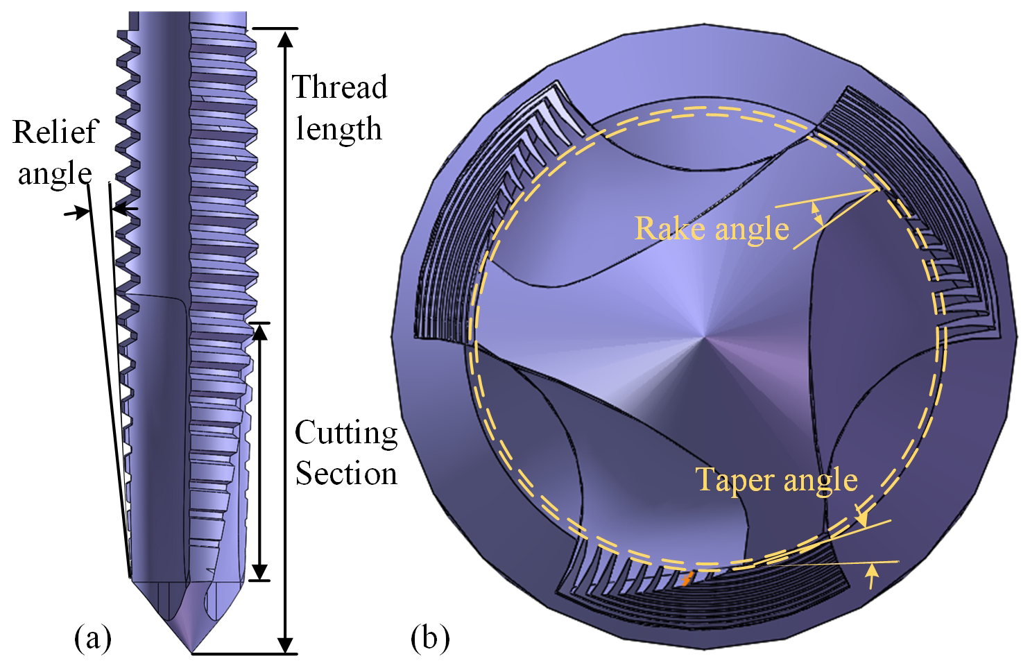
2.1 Spiral point tap geometric model
Figure 1 shows the 3D model of the spiral point tap, comprising the threaded section, shank, and holder. The threaded section is divided into the cutting zone, calibration zone, and back taper zone. The cutting zone features a helical structure responsible for material removal and is the primary region for torque generation. The calibration zone trims the thread profile to ensure dimensional accuracy. The back taper zone at the tail does not participate in cutting and has a slightly smaller major diameter than the calibration zone to reduce workpiece friction (Dos Santos Siqueira et al., 2019). The tap material is cobalt-containing high-speed steel, treated as a rigid body in the model. The rake angle is 21.9°, the taper angle is 8.1°, and the relief angle is 4.3°.
To enhance computational efficiency, the workpiece model is simplified to a 12 mm × 12 mm × 10 mm rectangular block with a through-hole of 2.4 mm diameter and 10 mm depth at its center. No chamfer is applied to the hole entrance as it is not the focus of this study.
2.2 Material parameters and constitutive model
Third Wave AdvantEdge software is employed for simulation, specifically designed for metal-cutting processes. AdvantEdge utilizes the Lagrange explicit time integration method combined with adaptive remeshing technology. The solver employs a dynamic explicit algorithm, integrating a centralized mass matrix with central difference time integration, making it particularly suitable for high-strain-rate and large-deformation problems. The tapping process involves material plastic deformation and separation, necessitating adequate consideration of high-strain and thermo-mechanical coupling effects in the material model (Li et al., 2002). This study uses the Johnson–Cook constitutive model to describe the mechanical behavior of Ti6Al4V under high strain, high strain rate, and elevated temperatures. Its expression is as follows:
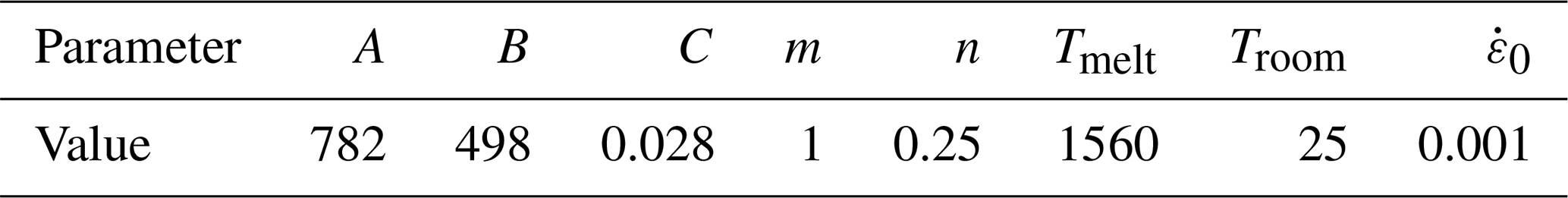
where A represents the material's initial yield stress (MPa), B is the material's strain hardening modulus (MPa), C represents the material's characteristic coefficient, m denotes the material's thermal softening coefficient, n is the material's strain hardening exponent, σ is the equivalent flow stress (MPa), ε is the equivalent elastic strain, is the equivalent plastic strain rate (s−1), is the reference equivalent elastic strain rate (s−1), T represents the workpiece deformation temperature (°C), Tmelt is the workpiece melting point (°C), and Troom represents room temperature (°C). Specific constitutive parameters for the model are listed in Table 1.
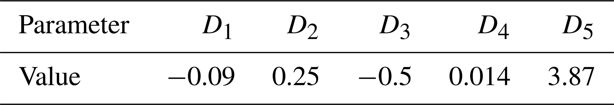
The equivalent plastic strain at failure is calculated using Eq. (2) (Wu and Zhang, 2014). This model defines the equivalent plastic strain at failure as a function of triaxial stress, strain rate, and temperature:
where p is hydrostatic pressure, q is von Mises stress, and D1–D5 is the failure parameter; see Table 2 for details.
Table 2Failure parameters of Ti6Al4V alloy (Wu and Zhang, 2014).
Accurate simulation of chip behavior is crucial for ensuring simulation precision in tapping. Selecting a reasonable chip separation criterion helps improve consistency between simulation results and the actual cutting process. This study adopts a physics-based chip separation criterion, determining whether stress, strain, and other parameters at nodes ahead of the tool tip reach the material failure threshold to achieve chip separation. The specific expression of this criterion is as follows:
where D is the damage factor, fracture occurs when D≥1, is the equivalent plastic strain increment, and is the failure strain.
The friction model comprehensively considers sliding- and adhesive-friction behavior. In the sliding zone, the friction stress is proportional to the normal stress, while, in the adhesive zone, it remains constant. According to friction and wear experiments conducted by Li et al. (2026) on Ti6Al4V alloy, the coefficient of friction between the tool and workpiece was determined to be 0.5. The friction coefficient in the model is set to 0.5, with the specific expression being as follows:
2.3 Meshing and boundary conditions
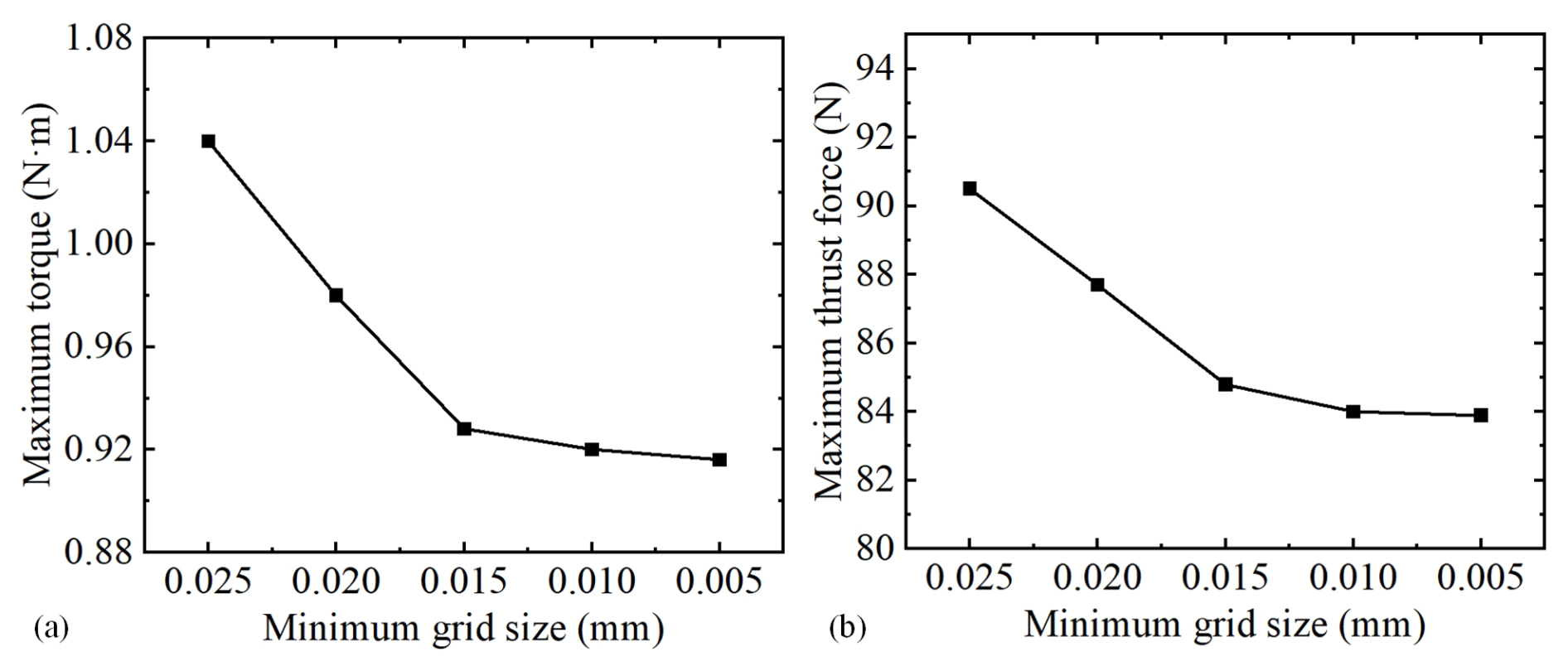
The ALE (adaptive Lagrange–Euler) adaptive mesh refinement method was adopted. This allows the mesh to be independent of material flow, dynamically adjusting the mesh structure during each iterative calculation, maintaining coupling between nodes and physical fields, thereby avoiding excessive mesh distortion and improving result accuracy. To further enhance model precision, user-defined meshing is employed, calculating the workpiece's minimum mesh length and refinement zone radius based on tap feed rate and radial depth of cut. After importing the tap STP file, the minimum mesh size and meshing level for the tap need adjustment (as shown in Fig. 2).
To ensure numerical objectivity and to verify mesh-independent results, a systematic mesh convergence study was performed. Specifically, the minimum element size in the tapping region was varied (0.025, 0.020, 0.015, and 0.010 mm), and the corresponding maximum torque and maximum thrust force were calculated under identical process parameters, as shown in Fig. 2. As the mesh was refined, both torque and thrust force exhibited a monotonically decreasing trend with gradually diminishing variations. From 0.025 to 0.020 mm, the torque decreased by 6.7 %, and the thrust force decreased by 3.3 %. From 0.020 to 0.015 mm, the torque decreased by 4.1 %, and the thrust force decreased by 1.1 %. From 0.015 to 0.010 mm, the torque changed by only 0.2 %, and the thrust force changed by 2.9 %. This indicates that, once the element size falls below 0.015 mm, the computational results stabilize and satisfy the requirements for mesh independence. Considering both computational accuracy and efficiency, a minimum element size of 0.015 mm was selected for subsequent analyses. Compared to the 0.010 mm mesh, the predictions obtained with this mesh show a torque deviation of less than 0.3 % and a thrust force deviation of less than 3 %, while the number of elements is reduced by approximately 40 %, significantly lowering computational cost.
The workpiece was meshed using linear tetrahedral elements, which were automatically generated by the software's built-in mesher. The tap was modeled as a rigid body and discretized with surface elements for contact interaction. During the cutting process, the adaptive meshing technique (ALE method) was applied to the workpiece, with a refined mesh around the pilot hole and coarser elements in non-cutting regions, as illustrated in Fig. 3. The maximum element size was set to 5 mm, and the minimum element size was set to 0.015 mm. A mesh refinement factor of 2 was used, and adaptive remeshing was performed every five time increments.
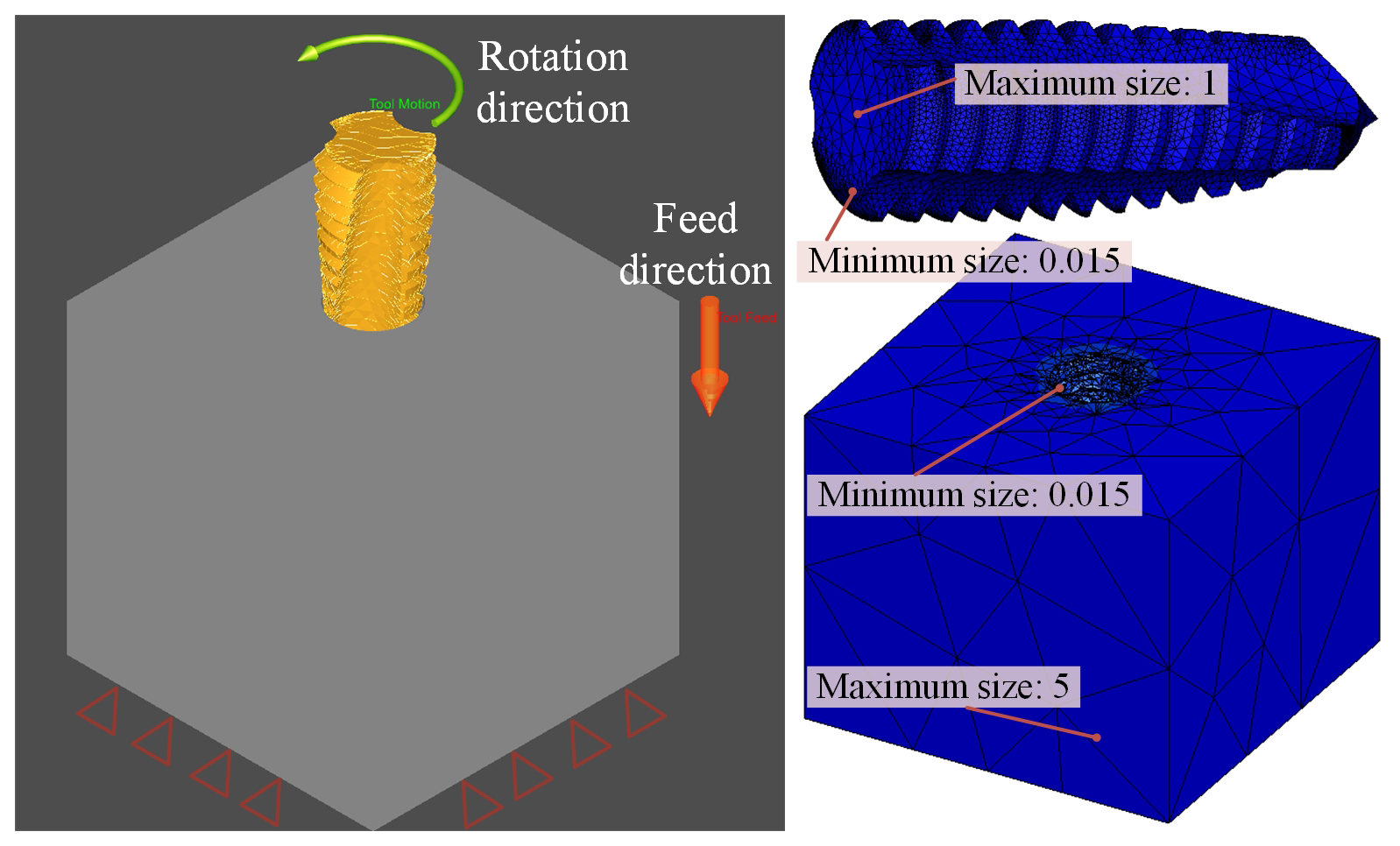
As shown in Fig. 3, the workpiece rotates around its axis with fixed orientation and moves along the positive Z-axis to simulate the tap's downward feed. The tap is fully constrained in axial translation and rotation about its axis. The tapping speed is set to 420 r min−1. For tap motion duration, the software's built-in tapping setting function is used, requiring only the definition of the tap rotation angle. To ensure complete entry of tap-cutting teeth into the pilot hole and considering the tap-cutting section length, the rotation angle is set to 4320° (12 revolutions). Establishing the Ti6Al4V alloy small model involves five steps: first, create and simplify the 3D models of the tap and workpiece; second, define the workpiece constitutive model and tap material properties; third, determine tapping parameters; fourth, set tapping boundary conditions and constrain the tap and tool; and, finally, mesh and verify accuracy.
3.1 Workpiece material and tool details
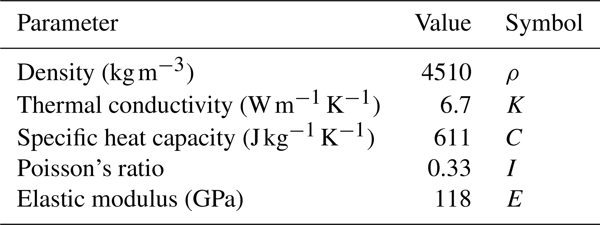
The Ti6Al4V alloy material was supplied by the manufacturer (BAOJI JIEMUTAI). After ultrasonic cleaning and metallographic sectioning, its chemical composition was determined using energy-dispersive spectroscopy (EDS), with results shown in Table 3. The alloy's mechanical properties are listed in Table 4. It should be noted that all material parameters listed in Table 4 are currently treated as temperature-independent constants. This simplification is based on the observation that the maximum temperature in simulations remains below approximately 250 °C, within which range material parameter variations are relatively minor. Furthermore, employing temperature-independent properties is a widely accepted simplification in cutting simulations (Zhang et al., 2012, 2011). For ease of operation and observation, the material was cut into 130 mm × 114 mm × 10 mm plate specimens, and a specialized fixture was designed to securely clamp them to the worktable.
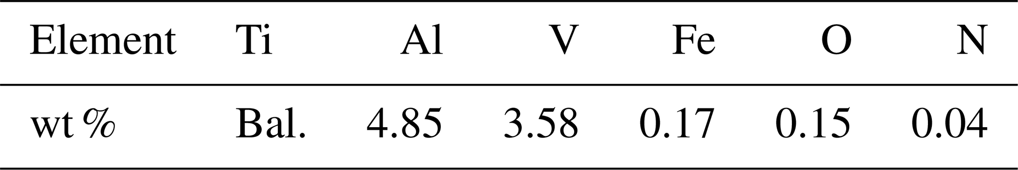
Table 4Thermo-mechanical properties of Ti6Al4V alloy (Li et al., 2023).
Due to low rotational speeds and small cutting velocities in small-diameter tapping, carbide tools are typically not used (Gill et al., 2012). This study selects uncoated powder metallurgy high-speed steel (M42 HSS-E-PM) spiral taps provided by Oiz. Pre-drilling pilot holes matching the tap specification are necessary before tapping; this experiment used carbide twist drills for this operation. The tap thread specification is 0.112-48UNJF, indicating a major diameter of 2.8448 mm) and 48 threads per inch. According to ISO 2306:1972, a 2.4 mm diameter drill was selected for the pilot hole. TiAlN-coated carbide drills have proven to be effective for obtaining high-quality holes in Ti6Al4V alloy (Saini et al., 2016). Additionally, to place a thermistor, a 1.5 mm diameter TiAlN-coated carbide drill was used to create an 8.5 mm deep blind hole 0.2 mm from the pilot hole center.
3.2 Ti6Al4V alloy small-sole tapping experimental platform
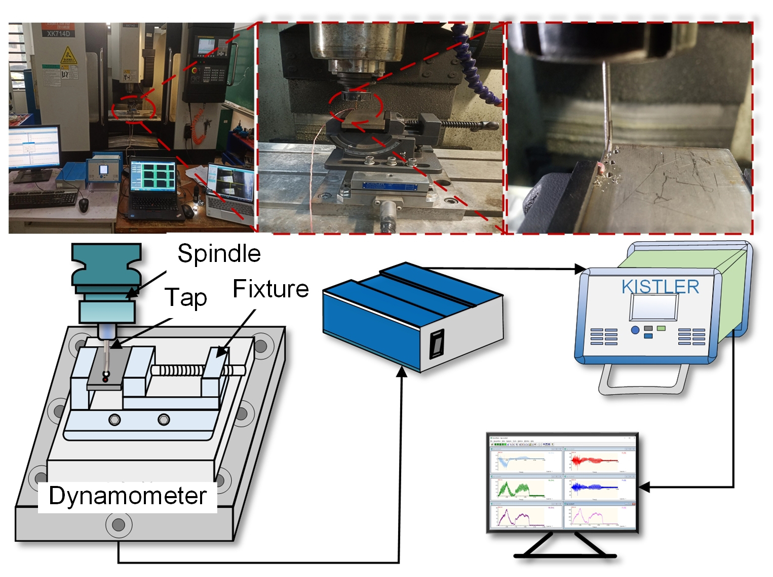
To validate the finite-element model accuracy, tapping experiments under dry conditions were conducted on a Hanchuan XK714D machine tool, with the experimental setup shown in Fig. 4. Before tapping, a through-hole was machined on the same machine as the pilot hole, and a blind hole was drilled for embedding the thermistor. Referencing previous research on Ti6Al4V drilling (Zhu, 2017), pilot hole drilling used a spindle speed of 6000 rpm and a feed rate of 15 mm min−1. To minimize thermal influence between adjacent holes, the center distance was set to 6 mm. All drilling and tapping operations were performed dry on the same milling machine. The machined pilot holes had a diameter of 2.4 mm and a depth of 10 mm. Each new drill was used only three times, and H7 hole gauges verified that hole diameters were within the 2.400–2.410 mm range. A Kistler 9257A dynamometer collected axial force and torque signals during tapping at a sampling frequency of 20 kHz. The output signals were amplified by a Kistler 5070 charge amplifier, transmitted via a data acquisition card to a computer, and processed using Dynoware software.
Based on experimentally measured tapping-force signals, the simulated torque and axial force values were verified through comparison. In the simulation, axial force and torque data were extracted throughout the entire 4320° rotation of the tap, and experimental measurements from the corresponding time interval were selected for comparison. Figure 5 displays the peak axial force and torque values from both experiments and simulations. The experimentally measured peak axial force was approximately 90 N, while the simulation result was approximately 84 N, representing a relative error of 6.7 %. This error falls within an acceptable range. The primary causes of the discrepancy include the simulation's idealized neglect of machine tool vibration and impact effects, as well as room for improvement in the mesh refinement accuracy.
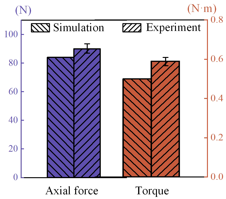
Torque is a key parameter that reflects the interaction between the tap and the workpiece during tapping. Torque results were validated experimentally; simulation data were extracted during post-processing and fitted into curves, as shown in Fig. 5. Simulation and experimental trends are consistent. The experimental peak was 1.00 N m, and the simulation result was 0.92 N m, showing an error of 8 %. Comparing the peaks and trends of axial force and torque validates the model's accuracy.
5.1 Thread formation mechanism
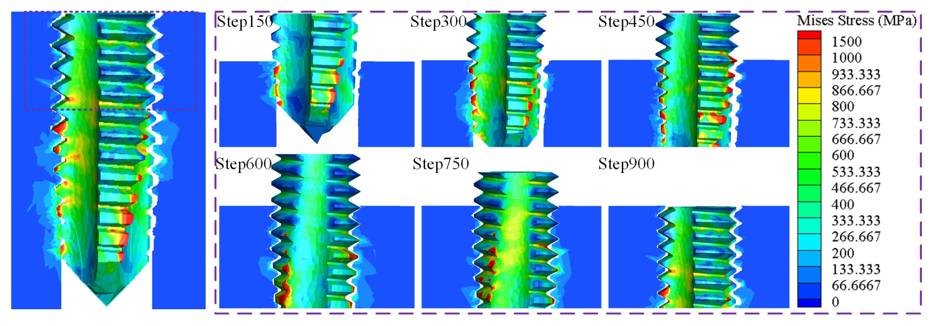
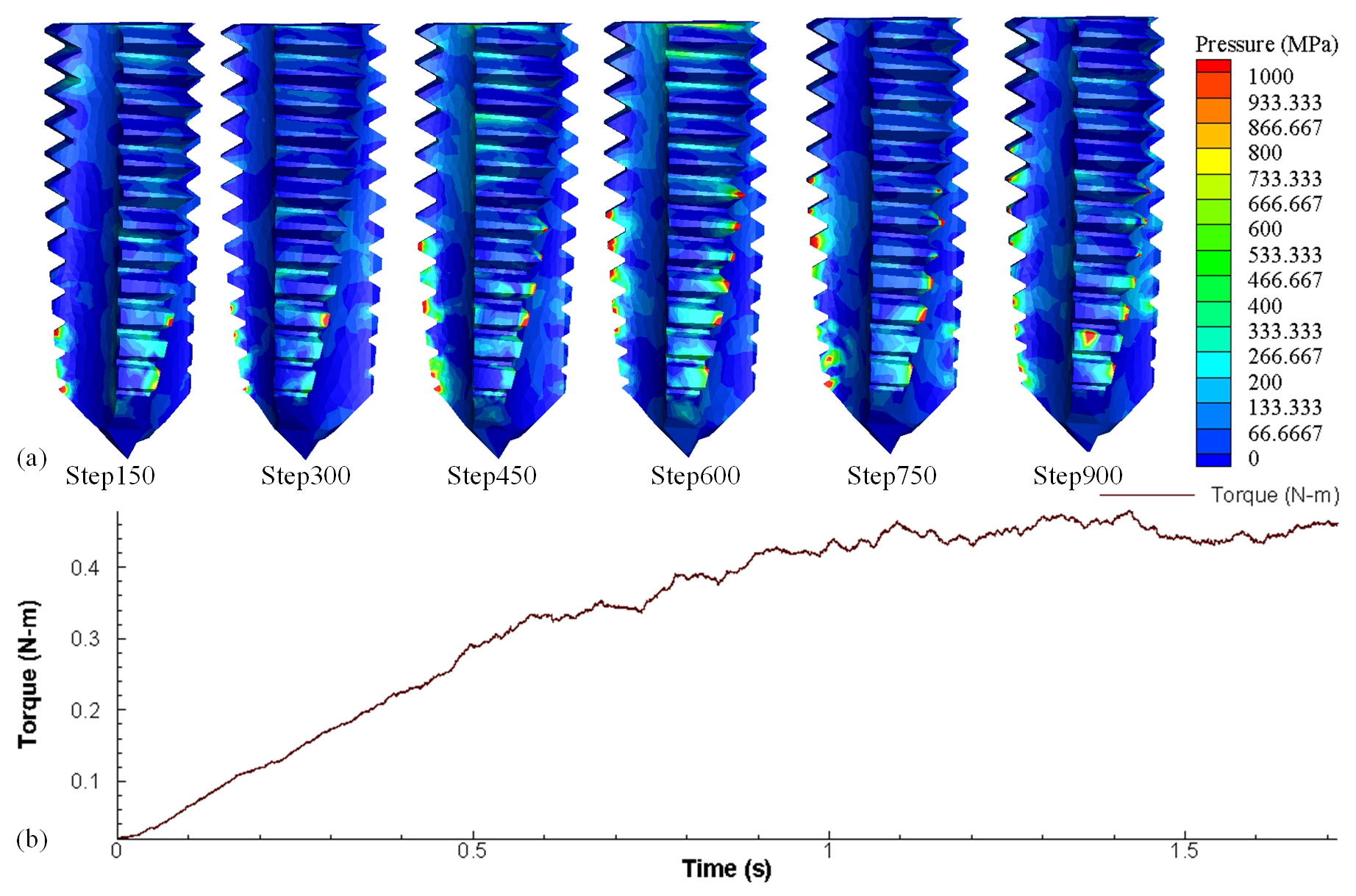
During tapping, thread formation is a typical progressive process combining material plastic deformation and cutting. In the initial stage (e.g., step 150), the front cutting teeth of the tap begin to penetrate the workpiece material, with significant local stress concentration. Von Mises stress can exceed 1000 MPa, indicating that the material is undergoing intense plastic yielding. As the tap advances further (step 300–step 600), the thread profile gradually becomes clear; the stress field expands from the front backwards; and stress in the formed thread region gradually releases but remains relatively high, suggesting continuous plastic flow and work hardening during forming. At higher step numbers (step 750–step 900), the thread morphology stabilizes, and stress distribution becomes more uniform, but stress concentration persists at the thread root and tap edge contact areas, reflecting the combined effects of material shearing, extrusion, and elastic recovery during formation.
5.2 Tapping-force analysis
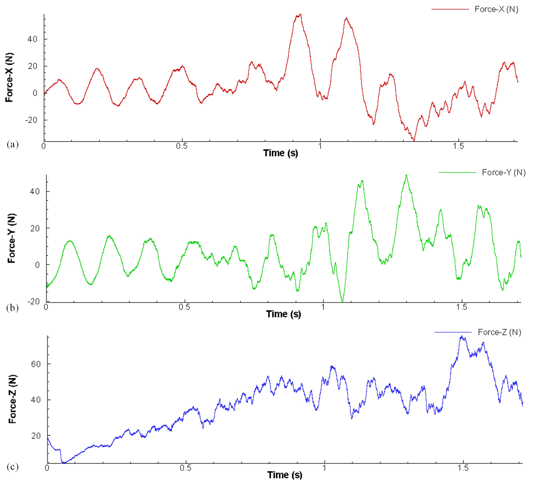
Figure 7 shows the force curves in the X, Y, and Z directions obtained from the finite-element simulation. The X and Y direction force curves exhibit strong, similar-amplitude periodic fluctuations centered around the zero line. This is one of the most significant dynamic characteristics of the tapping process because the tap itself has multiple flutes (cutting edges), and its structure is not axisymmetric. As the tap rotates, each cutting edge engages the material sequentially, generating an instantaneous radial-impact force whose direction changes with the tap angle. The forces in the X and Y directions are essentially the decomposition of this periodically varying radial force into two orthogonal directions. Within one complete rotation cycle, the radial forces in various directions theoretically cancel each other out, resulting in a net (average) radial force of zero. The curves fluctuate symmetrically around the zero axis, consistently with the force characteristics of a rotating cutting tool under ideal conditions. The fluctuation amplitude reflects the impact intensity of single-tooth cutting.
The Z-direction force curve shows a typical three-stage characteristic: “rapid rise–stable fluctuation–rapid decline”. This corresponds to the initial engagement of the tap's front cutting cone with the workpiece, where the engaged cutting-edge length and material contact area increase rapidly, causing a sharp rise in axial force. After full engagement, the working part (cutting cone and calibration cone) reaches a stable contact state with the workpiece (Zhang et al., 2026b). Here, the axial force fluctuates around a high average value. This fluctuation stems from two main factors: first, the tap's rotation, which causes each cutting tooth to cyclically engage and disengage the material, and, second, the inhomogeneity of the workpiece material and the continuous process of chip formation and fracture.
5.3 Tap temperature field analysis
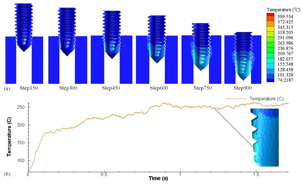
Tap tapping involves severe plastic deformation and friction, inevitably accompanied by significant heat generation. Analyzing the simulated temperature field contour (Fig. 8a) and the temperature–time curve (Fig. 8b) provides deep insight into the process's thermodynamic characteristics. The highest temperature is consistently concentrated at the tap's cutting edges and contact regions with the machined thread surface. Figure 8a displays the temperature distribution contour map of the workpiece area surrounding the threaded hole and the tap surface. It can be observed that heat is primarily concentrated near the hole wall and gradually attenuates radially towards the interior of the workpiece, forming a distinct temperature gradient. This indicates that the cutting heat primarily originates from the intense friction and plastic deformation between the cutting edge and the workpiece material. As tapping progresses, heat accumulates and conducts outwards, gradually expanding the “heat-affected zone” around the tap itself and the workpiece thread hole.
During the initial tap engagement stage (0–0.1 s), the temperature curve rises steeply. This corresponds to the tap's cutting cone beginning to contact and compress the material, where plastic work and friction work instantly convert into substantial heat, causing a sharp temperature increase. After full engagement and entry into stable cutting (0.1–1.5 s), the temperature reaches a relatively stable high plateau (around 200 °C) with minor fluctuations. This is due to a dynamic balance between heat generation and dissipation (via chip, workpiece, and tool conduction), and fluctuations arise from the periodic engagement and disengagement of cutting edges during rotation, causing cyclic changes in heat source intensity.
5.4 Tap pressure field analysis
Figure 9a and b show the tap pressure field and torque curve obtained from the finite-element model. Extremely high contact pressures (up to 1000 MPa) are concentrated on the tap's cutting edges and the contact areas between the tap margin (calibration section) and the machined thread flank. This indicates that the material withstands extreme pressure not only at the instant of cutting but also continuously on the formed thread surface due to elastic recovery and tool extrusion. As tapping proceeds, the pressure in the formed thread section stabilizes but remains high, indicating that the tap calibration section sustains extrusion and friction throughout the process.
The torque–time curve, as shown in Fig. 9b, quantitatively describes the rotational moment required throughout tapping, with its growth trend resembling the axial force. It is worth noting that the torque curve represents the sum of the tangential forces acting on all cutting edges of the tap (Zhang et al., 2026a). During initial engagement, torque increases sharply with the rapid increase in contact area between tap and workpiece. Torque in this stage primarily overcomes initial material shear resistance and friction at the front cutting edges. After full engagement, torque enters a relatively stable high plateau with noticeable periodic fluctuations. The curve's periodic fluctuations directly relate to the number of tap flutes. Each cutting edge cyclically engages and disengages the material, causing regular variations in instantaneous torque. These fluctuations directly manifest the multi-edge cutting characteristic of the tap.
5.5 Chip analysis
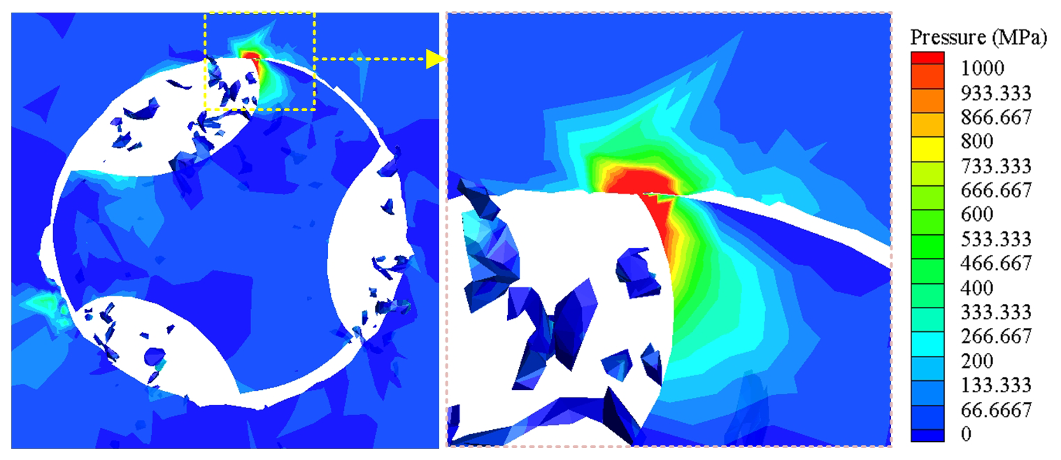
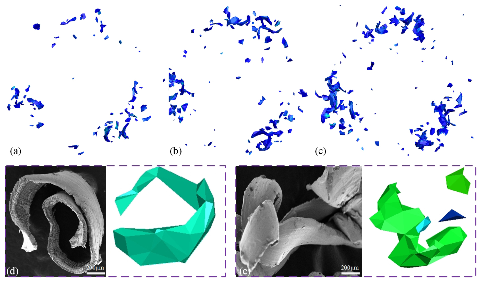
Chip morphology is a key indicator for assessing cutting state and tap performance (Bai et al., 2017) as its shape, size, and surface condition directly influence tapping stability, friction heat distribution, and tool life. From the cross-sectional stress contour of the tap and workpiece (Fig. 10), particularly the enlarged view near the tool tip, the key physical process of material removal during tapping can be clearly observed. The core mechanism involves continuous shear and slip of the workpiece material under high pressure by the tap's cutting edge. Stress values are highest on the tool tip and rake face (surface contacting the chip), as indicated by the red areas. This shows that the tool tip is the forefront for material extrusion and penetration, while the rake face withstands immense friction and pressure from chip formation and flow. The rotating, advancing tap-cutting edge first compresses the workpiece material, causing elastic deformation. When stress exceeds the material's yield strength, concentrated plastic shear slip occurs in the primary deformation zone ahead of the tool tip. Continuous shear slip eventually completely separates a portion of the material, forming the chip, which is evacuated upwards along the tap's rake face and flute. Figure 11a–c show chips obtained at different times. Since the tap has three chip evacuation channels, three separate chip sections are formed. Figure 11d and e compare and verify the chip morphology obtained from experiments and simulations. The chips are predominantly “strip-like” and “cluster-like”, with consistent morphological features, indicating good predictive reliability of the established finite-element model. The curled chips shown in Fig. 11d exhibit a continuous and regular morphology consistent with the stable cutting phase simulated. The disordered, tangled chips in Fig. 11e primarily occur during chip removal difficulties or accumulation, reflecting the complexity of chip flow in actual tapping processes (Liu et al., 2024).
This paper conducts a comprehensive numerical simulation study of the tapping process via finite-element analysis, yielding the following main conclusions:
- 1.
The formation of threads is essentially a continuous shearing process performed by the cutting edges of a tap under high pressure. Stress contour plots clearly reveal the stress concentration zone ahead of the cutting edge, where concentrated plastic slip occurs in the material. This ultimately leads to separation and chip formation, progressively shaping the thread profile.
- 2.
During tapping, the tap undergoes significant tri-axial loads. The axial force (Z direction) is the primary resistance, with the largest steady-state value; due to tap rotation and multi-edge structure, radial forces in the X and Y directions manifest as periodic alternating forces, a dynamic load contributing significantly to tap fatigue.
- 3.
Extremely high contact pressure concentrates on the cutting edges and tap margin areas. This pressure field is the root cause of substantial frictional torque, making the total driving torque comprise both “cutting torque” and “frictional torque”. The periodic fluctuations in the torque curve directly reflect the intermittent nature of multi-edge cutting.
- 4.
Heat generated during cutting leads to localized high temperatures at the cutting edges, forming steep temperature gradients. High temperatures can induce material thermal softening; affect flow stress; and, collectively with high stress and friction, create an extreme thermo-mechanical coupled environment.
Although the finite-element model established in this study has been experimentally validated and provides valuable industrial insights for the tapping process, certain limitations must be acknowledged, and relevant future research directions are proposed.
Modeling limitations and uncertainties. First, although a mesh convergence study was conducted, the selected mesh size represents a compromise between computational cost and accuracy. Second, the use of a constant friction coefficient and temperature-independent material properties simplifies the complex interface behavior during tapping. Actual interface behavior and material properties vary with temperature. Additionally, the model neglects thermal boundary conditions involving convective and radiative heat transfer.
Future work. Subsequent research will focus on optimizing the mesh size and developing a temperature- and pressure-coupled friction model to more accurately describe interfacial behavior. A tapping model incorporating precise convective boundary conditions will be developed. Furthermore, a finite-element model for tapping considering progressive tap wear will be established, incorporating temperature-dependent material properties to accurately predict tap life.
The datasets used or analyzed during the current study are available from the corresponding author on reasonable request.
Conceptualization: GW, LXF, and MXK. Data collection: GW and MXKl. Methodology: LXF and ZWJ. Validation: GW. Resources: QY and YX. Writing (original draft): GW, GQ, and ZJW. Writing (review and editing): GW and LXF. Supervision: MXK, GQ, and ZJW.
The contact author has declared that none of the authors has any competing interests.
Publisher's note: Copernicus Publications remains neutral with regard to jurisdictional claims made in the text, published maps, institutional affiliations, or any other geographical representation in this paper. The authors bear the ultimate responsibility for providing appropriate place names. Views expressed in the text are those of the authors and do not necessarily reflect the views of the publisher.
This paper was edited by Yancheng Zhang and reviewed by two anonymous referees.
An, Q., Cai, C., Zou, F., Liang, X., and Chen, M.: Tool wear and machined surface characteristics in side milling Ti6Al4V under dry and supercritical CO2 with MQL conditions, Tribol. Int., 151, 106511, https://doi.org/10.1016/j.triboint.2020.106511, 2020.
Bai, D., Sun, J., Chen, W., and Wang, T.: Wear mechanisms of WC/Co tools when machining high-strength titanium alloy TB6 (Ti-10V-2Fe-3Al), Int. J. Adv. Manuf. Technol., 90, 2863–2874, https://doi.org/10.1007/s00170-016-9607-z, 2017.
Barooah, R. K., Paiva, J. M., Arif, A. F. M., Rawal, S., Bose, B., and Veldhuis, S. C.: Investigation on wear mechanisms of PVD coatings for form taps in threading of Al–Si alloy, Wear, 464–465, 203528, https://doi.org/10.1016/j.wear.2020.203528, 2021.
Biermann, D. and Oezkaya, E.: CFD simulation for internal coolant channel design of tapping tools to reduce tool wear, CIRP Ann., 66, 109–112, https://doi.org/10.1016/j.cirp.2017.04.024, 2017.
Brandão, G. L., Silva, P. M. D. C., De Freitas, S. A., Pereira, R. B. D., Lauro, C. H., and Brandão, L. C.: State of the art on internal thread manufacturing: a review, Int. J. Adv. Manuf. Technol., 110, 3445–3465, https://doi.org/10.1007/s00170-020-06107-x, 2020.
Chen, F., Wang, D., and Wu, S.: Influence of ultrasonic vibration-assisted cutting on ploughing effect in cutting Ti6Al4V, Arch. Civ. Mech. Eng., 21, 42, https://doi.org/10.1007/s43452-021-00196-5, 2021.
Davoudinejad, A., Chiappini, E., Tirelli, S., Annoni, M., and Strano, M.: Finite Element Simulation and Validation of Chip Formation and Cutting Forces in Dry and Cryogenic Cutting of Ti–6Al–4V, Procedia Manuf., 1, 728–739, https://doi.org/10.1016/j.promfg.2015.09.037, 2015.
Demirel, T., Yağmur, S., Kayır, Y., and Kurt, A.: Finite element simulation of stresses in cutting tools during tapping, Simul. Model. Pract. Theory, https://doi.org/10.21203/rs.3.rs-1710771/v1, in review, 2022.
Dos Santos Siqueira, B., Freitas, S. A., Pereira, R. B. D., Lauro, C. H., and Brandão, L. C.: Influence of chip breaker and helix angle on cutting efforts in the internal threading process, Int. J. Adv. Manuf. Technol., 102, 1537–1546, https://doi.org/10.1007/s00170-018-3165-5, 2019.
Gill, S. S., Singh, R., Singh, J., and Singh, H.: Adaptive neuro-fuzzy inference system modeling of cryogenically treated AISI M2 HSS turning tool for estimation of flank wear, Expert Syst. Appl., 39, 4171–4180, https://doi.org/10.1016/j.eswa.2011.09.117, 2012.
Li, J., Wang, Y., Liu, K., Zhao, D., Jiang, S., Yang, Y., and Yu, Q.: Tough-brittle transition mechanism and specific cutting energy analysis during cryogenic machining of Ti–6Al–4V alloy, J. Clean. Prod., 383, 135533, https://doi.org/10.1016/j.jclepro.2022.135533, 2023.
Li, K., Gao, X.-L., and Sutherland, J. W.: Finite element simulation of the orthogonal metal cutting process for qualitative understanding of the effects of crater wear on the chip formation process, J. Mater. Process. Technol., 127, 309–324, https://doi.org/10.1016/S0924-0136(02)00281-9, 2002.
Li, Z., Tang, Z., Duan, Y., Feng, Z., Ma, L., Zheng, S., Peng, M., and Li, M.: Microstructure and wear properties of B-Al layer on Ti6Al4V titanium alloy by boron-aluminizing with rare-earth oxide, Tribol. Int., 213, 111050, https://doi.org/10.1016/j.triboint.2025.111050, 2026.
Liu, C., Zhang, J., Liu, J., and Wang, K.: Machinability based cooling/lubrication strategies in tapping within small holes of Ti6Al4V alloy, J. Manuf. Process., 131, 1565–1581, https://doi.org/10.1016/j.jmapro.2024.09.121, 2024.
Mathurin, F., Guillot, J., Stéphan, P., and Daidié, A.: 3D Finite Element Modeling of an Assembly Process With Thread Forming Screw, J. Manuf. Sci. Eng., 131, 041015, https://doi.org/10.1115/1.3160377, 2009.
Miguélez, M. H., Soldani, X., and Molinari, A.: Analysis of adiabatic shear banding in orthogonal cutting of Ti alloy, Int. J. Mech. Sci., 75, 212–222, https://doi.org/10.1016/j.ijmecsci.2013.06.011, 2013.
Oezkaya, E. and Biermann, D.: Development of a geometrical torque prediction method (GTPM) to automatically determine the relative torque for different tapping tools and diameters, Int. J. Adv. Manuf. Technol., 97, 1465–1479, https://doi.org/10.1007/s00170-018-2037-3, 2018.
Patel, H. J., Patel, B. P., and Patel, S. M.: A Review on Thread Tapping Operation and Parametric Study, Int. J. Eng., 2, 109–113, 2012.
Pawar, S. and Joshi, S. S.: Experimental analysis of axial and torsional vibrations assisted tapping of titanium alloy, J. Manuf. Process., 22, 7–20, https://doi.org/10.1016/j.jmapro.2016.01.006, 2016.
Saini, A., Pabla, B., and Dhami, S.: Developments in cutting tool technology in improving machinability of Ti6Al4V alloy: A review, Proc. Inst. Mech. Eng. Part B J. Eng. Manuf., 230, 1977–1989, https://doi.org/10.1177/0954405416640176, 2016.
Saito, Y., Takiguchi, S., Yamaguchi, T., Shibata, K., Kubo, T., Watanabe, W., Oyama, S., and Hokkirigawa, K.: Effect of friction at chip–tool interface on chip geometry and chip snarling in tapping process, Int. J. Mach. Tools Manuf., 107, 60–65, https://doi.org/10.1016/j.ijmachtools.2016.05.004, 2016.
South Ural State University, Chelyabinsk, Russian Federation, Shchurov, I. A., Boldyrev, I. S., and South Ural State University, Chelyabinsk, Russian Federation: FE-modeling of tapping for calculating the virtual pitch thread diamete, Bull. South Ural State Univ. Ser. Mech. Eng. Ind., 23, 73–80, https://doi.org/10.14529/engin230107, 2023.
Wu, H. B. and Zhang, S. J.: 3D FEM simulation of milling process for titanium alloy Ti6Al4V, Int. J. Adv. Manuf. Technol., 71, 1319–1326, https://doi.org/10.1007/s00170-013-5546-0, 2014.
Zhang, J., Liu, C., Wei, L., and Zhou, Q.: A novel flank grinding strategy for reduced friction and extended tool life in small hole tapping of Ti6Al4V, J. Manuf. Process., 164, 339–358, https://doi.org/10.1016/j.jmapro.2026.02.072, 2026a.
Zhang, J., Liu, C., Wei, L., and Zhou, Q.: Revealing the wear characteristics, mechanisms, and failure of PM-HSS taps in Ti6Al4V alloy: Insights from tap life testing and tribological behavior, Tribol. Int., 217, 111608, https://doi.org/10.1016/j.triboint.2025.111608, 2026b.
Zhang, Y., Mabrouki, T., Nelias, D., Courbon, C., Rech, J., and Gong, Y.: Cutting simulation capabilities based on crystal plasticity theory and discrete cohesive elements, J. Mater. Process. Technol., 212, 936–953, https://doi.org/10.1016/j.jmatprotec.2011.12.001, 2012.
Zhang, Y. C., Mabrouki, T., Nelias, D., and Gong, Y. D.: Chip formation in orthogonal cutting considering interface limiting shear stress and damage evolution based on fracture energy approach, Finite Elem. Anal. Des., 47, 850–863, https://doi.org/10.1016/j.finel.2011.02.016, 2011.
Zhu, Z., Sui, S. C., Sun, J., Li, J. F., and Li, Y. L.: Investigation on performance haracteristics in drilling of Ti6Al4V alloy, Int. J. Adv. Manuf. Technol., 93, 651–660, https://doi.org/10.1007/s00170-017-0508-6, 2017.
- Abstract
- Introduction
- 3D numerical model establishment for Ti6Al4V alloy small-hole tapping
- Ti6Al4V alloy small-hole tapping experiment
- Validation and analysis
- Finite-element analysis results
- Conclusion
- Limitations and future work
- Data availability
- Author contributions
- Competing interests
- Disclaimer
- Review statement
- References