the Creative Commons Attribution 4.0 License.
the Creative Commons Attribution 4.0 License.
 | 26 Mar 2026
Mechanical analysis of historical crossbows
Zhe-Ran Wang
Yang Zhang
Chieh-Ya Lin
Kuo-Hung Hsiao
The crossbow evolved from the traditional bow through the incorporation of a stock and trigger mechanism, enabling the crossbow archer to retain the accumulated elastic energy of the bow and string. This design overcame limitations such as difficulty maintaining aim for extended periods, reduced shooting accuracy, and limited range. The shooting process of a crossbow consists of four main steps: string drawing, bolt loading, string releasing, and bolt launching. The principal difference between Eastern and Western crossbows lies in the method of drawing the string. Ancient Chinese crossbows used either manual force or linkage mechanisms. Early European crossbows additionally employed gear mechanisms to facilitate string drawing. The mechanical configuration of a crossbow changes during shooting. Therefore, it is classified as a variable-topology mechanism. This paper applies graph representations to illustrate the mechanical structural changes in historical crossbows from both China and Europe. First, the historical development of crossbows in the East and West is briefly reviewed. Then, the motion characteristics of the earliest documented repeating crossbow, lever-type crossbow, and cranequin crossbow are analyzed. Graph representations and 3D computer models are used to visualize the topological variations in these three crossbow types and their shooting processes. Finally a cross-cultural comparison of ancient crossbows is provided.
- Article
(4890 KB) - Full-text XML
- BibTeX
- EndNote


Traditional bow-and-arrow systems are operated by drawing the bowstring through human effort and bending both the string and the bow to induce elastic energy. Upon release, the bow returns to its original shape and releases the accumulated energy to launch the nocked arrow with great force. Arrowheads fashioned from stone have been found in 10 000-year-old Paleolithic sites, and large quantities of arrowheads made from either stone or animal bone have been found in subsequent Neolithic sites. These findings indicate that prehistoric humans progressed from hunting by throwing stones to manufacturing and using bows and arrows. This advancement continued with the development of a variety of ranged weaponry, shaping the history of projectile arms for millennia (Needham, 1954).
Attaching a stock and trigger mechanism to the bow gave rise to the crossbow. Its shooting sequence involved four key steps – drawing the string, nocking the projectile (bolt), releasing the string, and firing. This weapon had profound influence. Eastern and Western civilizations independently developed crossbows with distinctive mechanical designs (Hsiao, 2013; Hsiao and Yan, 2014). Single-shot crossbows can be traced to the 6th century BCE, representing one of the most characteristic weapons of ancient China (McNab, 2012). The repeating crossbow emerged no later than the first half of the 3rd century BC and underwent significant improvements in the 2nd century CE (Loades, 2018). In Europe, crossbows first appeared in documents from the 2nd century BCE and became widespread from the 12th century onward. By the 14th and 15th centuries, spanning mechanisms equipped with linkages or gears were introduced to assist crossbow archers in drawing the increasingly powerful bows and strings that substantially enhanced the crossbow's lethality (Ford and Grant, 2006). Throughout the shooting process, the crossbow's mechanical configuration changes. This is classified as a variable-topology mechanism. The present study analyzed the mechanical structures of representative crossbows from Eastern and Western traditions. This paper first outlines the historical development of crossbows in these regions and then examines the constrained motions of three key crossbow types – the repeating crossbow, the lever-type crossbow, and the cranequin crossbow. It presents schematic representations and 3D computer illustrations to demonstrate the structural transformations and shooting processes of these crossbows. Finally, a comparison of the historical crossbows is discussed.
As illustrated in Fig. 1, ancient Chinese crossbows comprised a stock (KF), a bow (KCB), and a bowstring (KT), along with a trigger mechanism consisting of mechanical components such as the input link (KPL), the percussion link (KPL), and the connecting link (KL). The earliest written record of Chinese crossbows appeared in The Art of War (498 BCE; Sun, 2019). The oldest excavated crossbow trigger mechanism, unearthed in Qufu, Shandong Province, dates to the 6th century BCE (Zhang et al., 2004). The key technological feature of the ancient Chinese crossbow was its bronze trigger mechanism, which enabled the crossbow archer to retain the elastic energy stored in the bow and bowstring without maintaining manual tension on the string and to discharge one arrow at a time. This innovation effectively addressed several weaknesses of traditional archery (e.g., limited aiming duration, low accuracy, and short range). Before the 2nd century CE, the components of trigger mechanisms were mounted directly onto the wooden stock. After the 2nd century CE, these components were housed within a bronze case before being installed in the stock, enabling greater tension than that provided using direct wooden mounting, thereby extending the weapon's effective range. Since the 2nd century CE, Chinese crossbows underwent few structural changes, although their sizes and ranges increased. Based on size and function, ancient Chinese crossbows were categorized into large mechanical crossbows and small handheld crossbows. Large mechanical crossbows typically combined multiple bows and incorporated mechanical cocking devices to enhance power and stability. Small handheld crossbows generated less force but offered superior agility and maneuverability. Until the Qing dynasty (1644–1911 CE), single-shot crossbows remained standard military equipment and represented one of the most distinctive weapon systems of ancient China.
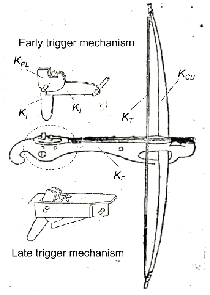
Figure 1Single-shot crossbow from ancient China (Mao, 2001).
The repeating crossbow featured an ingenious mechanical design. By manipulating the input link, the operator could complete the four steps of shooting – drawing, loading, releasing, and launching. In 1986, archeologists unearthed a repeating crossbow from a tomb in Hubei Province, dating to the first half of the 3rd century BCE. The weapon featured a 20-bolt magazine and could fire two arrows simultaneously, suggesting that such repeating crossbows may have emerged even earlier (Chen, 1990). Records of the Three Kingdoms (Chen, 2020) documented that the military strategist Zhuge Liang (181–234 CE) improved the crossbow capable of firing arrows in rapid succession. Later generations named this device the Zhuge repeating crossbow. Historical accounts noted that the weapon launched iron bolts about 8 cun (1 cun is approximately 3.3 cm) in length, firing one bolt at a time for a total of 10 consecutive shots. According to the Ming dynasty treatise, Wubei Zhi (Mao, 2001), the Zhuge repeating crossbow had a relatively short range; thus, poison was applied to the bolt heads to enhance its lethality. After the Song dynasty (960–1219 CE), the Zhuge repeating crossbow became standard military equipment and continued to be used until the First Sino–Japanese War (1894–1895 CE) (Payne-Gallwey, 1995). Since its invention, its basic structure had undergone few modifications, making it one of the most enduring projectile weapons in Chinese history.
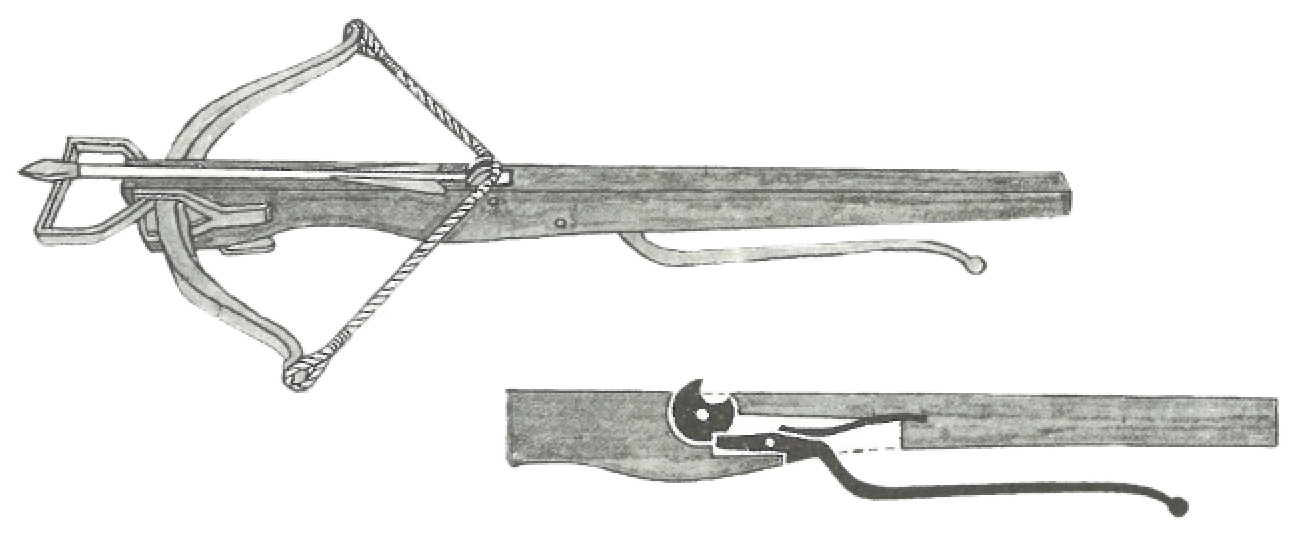
In Europe, the use of the crossbow can be traced back to the Roman period of the 1st century BCE, when it was primarily employed in siege warfare. Due to its excessive weight, it was ineffective against agile cavalry forces and eventually disappeared together with the Roman Empire. During the two centuries of the Crusades (1096–1291 CE), Crusader forces refined the weapon and developed a more powerful version known as the foot-stirrup crossbow. As illustrated in Fig. 2, this improved design comprised a stock (KF), bow (KCB), and bowstring (KT), together with a curved input link (KI), a cylindrical rotatable percussion link (KPL), and a spring (KS) connected to the input link. With these advancements, the Western crossbow evolved into a truly formidable weapon on the battlefield.
By the late 14th century, Europeans sought to extend the range of bolts by constructing bows and bowstrings of much greater strength, thereby requiring high-tension strings, which were challenging to draw. Accordingly, Europeans devised various mechanical cocking mechanisms that reduced the effort required for spanning. Examples included the lever-type cocking mechanism (goat's foot lever), which operated through a linkage mechanism, and the gear-driven cocking mechanism (cranequin), which used a gear and rack system (McNab, 2012). The goat's foot lever offers a mechanical advantage of 5:1, meaning that applying one unit of force can generate five units of pulling force, while the cranequin can provide a mechanical advantage as high as 145:1, enabling it to be used with heavy steel crossbows requiring a draw weight of over 360 kg (Loades, 2018).
The crossbow emerged as one of the most distinctive weapons of medieval Europe. The crossbow offered key advantages over the contemporary longbow. It delivered greater armor-penetrating power and could be held loaded, making it ideal for siege and defensive operations. Its spanning mechanisms reduced physical strain, allowing the use of heavier bows with minimal training. Continual technical innovations, like steel lathes and precision triggers, enhanced its effectiveness and prestige (Gorman, 2016). These advantages fundamentally reshaped the conduct of warfare in medieval Europe. With the introduction of the crossbow, even a peasant, after limited practice, could kill a heavily armored knight – an act that undermined the long-standing social hierarchy in which knights earned their titles through years of martial training. In response, knightly orders repeatedly appealed to the Church to prohibit the use of crossbows. Practical military needs rendered such bans ineffective, and armies across Europe continued to deploy the weapon, incorporating diverse mechanical innovations that gave rise to numerous crossbow designs (McNab, 2012).
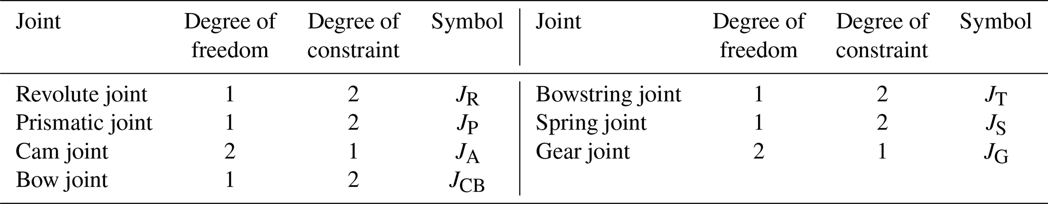
A mechanism is a device consisting of mechanical members connected by joints, and these members are formed and connected in such a way as to transmit constrained motion (Hsiao and Yan, 2014). It can be classified as a planar or spatial mechanism by its moving space. For planar mechanisms, a member has 3 degrees of freedom, including translational motions along two mutually perpendicular axes and a rotational motion about any point. Joints in planar mechanisms are, for example, revolute joints, prismatic joints, cam joints, and gear joints. The sum of the joint's degrees of freedom and its degree of restraint is 3. For example, the degree of freedom of a revolute joint is 1, and its degree of constraint is 2. The degree of freedom of a cam joint is 2, and its degree of constraint is 1.
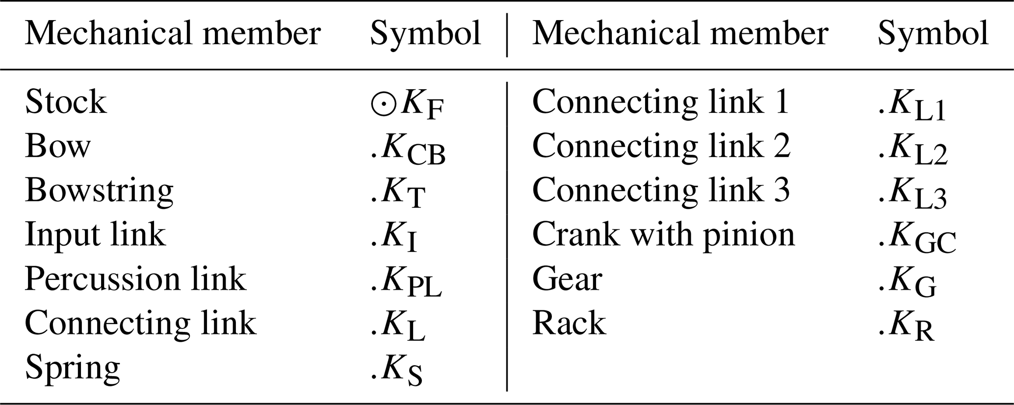
The topological structure of mechanisms refers to the number of mechanical members and joints and the connections among them (Yan, 1998, 2016). A mechanism whose topological structure changes during operation is defined as a variable-topology mechanism. For example, there is a mechanism with three operating stages, if the numbers and types of mechanical members and joints change in any stage. It can be referred to as a variable-topology mechanism. The graphical representation method provides an intuitive approach to illustrate the topological structure of a mechanism (Tsai, 2000). The shooting process of a crossbow consists of four steps – drawing, loading, releasing, and shooting – each corresponding to a distinct topological configuration. Therefore, the crossbow can be classified as a variable-topology mechanism. To represent the topological structure and motion relationships of crossbows, each mechanical member and joint is expressed as a vertex and an edge, respectively. Two vertices (or edges) are connected when their corresponding members (or joints) are physically linked (Yan, 1998). Based on this principle, the mechanical members of the crossbow are represented by vertices labeled with their respective names, as shown in Table 1, while the joints are represented by edges labeled with their joint types, degrees of freedom, and degrees of constraint, as listed in Table 2. The subscript in each joint symbol denotes its type: revolute, prismatic, and cam joints are represented by JR, JP, and JA, respectively. The bow is directly inserted into the stock, forming a bow joint JCB. This joint exhibits the same motion characteristics as a revolute joint – the relative movement between the connected components occurs as rotation about an axis – and its degree of freedom equals 1. The bowstring is directly tied to the bow, forming a string joint JT, which likewise behaves as a revolute joint with a degree of freedom of 1. The spring is mounted on the stock and directly contacts the input link, forming a spring joint JS. This joint also functions similarly to a revolute joint and has a degree of freedom of 1.
The Zhuge repeating crossbow, the lever-type crossbow, and the gear-driven crossbow were used as representative examples for analyzing variations in topological structure and for examining the constrained motion involved in the shooting process. The analysis employed the graphical representation method to illustrate structural transformations during operation.
4.1 Zhuge repeating crossbow
According to historical records, the Zhuge repeating crossbow comprised a stock (KF), bow (KCB), bowstring (KT), input link (KI), and percussion link (KPL) for drawing the string, as shown in Fig. 3a (Hsiao and Yan, 2014). The percussion link was positioned above the stock and featured a magazine housing 10 bolts in a longitudinal chamber. During operation, the operator first pushed the input link forward, allowing the percussion link to hook the bowstring. The operator then pulled the input link backward. At the lowest point of the pull, a small protrusion on the stock made contact with the bowstring, causing the string to disengage from the percussion link and propel the bolt. After each shot, the next bolt in the magazine dropped automatically due to gravity, preparing the weapon for the subsequent firing cycle.

Because the bolts descended automatically due to gravity, the shooting process of the Zhuge repeating crossbow consisted of four sequential stages: string hooking, string drawing, string releasing, and bolt launching. Each stage is described in detail below.
4.1.1 String hooking
During this stage, both the bow and the bowstring remained stationary. The input link was pushed forward and connected to the stock and the percussion link with the magazine through revolute joints JR. The percussion link was further connected to the stock via a cam joint JA. The corresponding 3D model and graphical representation are shown in Figs. 4a and 5a, respectively. Once the bowstring was successfully hooked, as illustrated in Fig. 4b1, the process proceeded to the second stage.
This stage comprised three mechanical members, two revolute joints, and one cam joint. Therefore, NL = 3, CpR = 2, NJR = 2, CpA = 1, and NJA = 1. The degree of freedom Fp for this step was calculated as follows:
Hence, the motion during this stage was constrained.
4.1.2 String drawing
When the input link reached its foremost position, the notch at the lower end of the percussion link hooked the bowstring. The input link was then pulled backward while remaining connected to both the stock and the percussion link via revolute joints JR. The percussion link and stock were connected by a cam joint JA. The bow was attached to the stock and bowstring through a bow joint JCB and a bowstring joint JT, respectively. As the bowstring was directly stretched by the percussion link, it was treated as being connected through the bowstring joint JT. The corresponding 3D model and graphical representation are presented in Figs. 4b2 and 5b.
This stage involved five mechanical members, two revolute joints, one cam joint, one bow joint, and two bowstring joints. Therefore, NL = 5, CpR = 2, NJR = 2, CpA = 1, NJA = 1, CpCB = 2, NJCB = 1, CpT = 2, and NJT = 2. The degree of freedom Fp for this step was derived as follows:
Thus, the motion during this stage was also constrained.
4.1.3 String releasing
When the input link reached its rearmost position, as illustrated in Fig. 4c, the bowstring was pushed by the protrusion on the stock, disengaging from the notch of the percussion link. Because the protrusion had an irregular geometry, the connection between the bowstring and the stock protrusion was represented as a cam joint JA. The other link relationships were identical to those in the string-drawing stage. The corresponding 3D model and graphical representation are shown in Figs. 4c and 5c.
This stage consisted of five mechanical members, two revolute joints, one bow joint, two bowstring joints, and two cam joints. Accordingly, NL = 5, CpR = 2, NJR = 2, CpCB = 2, NJCB = 1, CpT = 2, NJT = 2, CpA = 1, and NJA = 2. The degree of freedom Fp for this step was calculated as follows:
Because the degree of freedom equaled zero, the mechanismwas theoretically immobile. In practice, the bowstring is a flexible member, and the elasticity of the bowstring allowed the protrusion on the stock to push the bowstring out of the percussion link's notch, thereby completing the release stage. The comparison of degrees of freedom per each stage is listed in Table 3.
4.1.4 Bolt launching
When the bowstring disengaged from the percussion link, the elastic energy accumulated in the bow and bowstring was released, propelling the bolt forward. During this stage, both the input link and the percussion link remained stationary, awaiting the next shooting cycle. The bow was connected to the stock and bowstring via a bow joint JCB and bowstring joint JT, respectively, and the bowstring was attached to the stock through a prismatic joint JP. The corresponding 3D model and graphical representation are illustrated in Figs. 4d and 5d.
4.2 Lever-type crossbow
The trigger mechanism of early European crossbows incorporated a spring plate, creating a design distinct from that of ancient Chinese crossbows (Fig. 2). During shooting, the operator pressed the input link to cause the beak-shaped tip at its front end to disengage from the notch of the percussion link, allowing the percussion link to rotate and release the bowstring. This trigger mechanism exhibited lower sensitivity but offered greater operational safety by preventing accidental discharge.
To enhance the bolt's range and striking power, European artisans increased the strength of the bow and bowstring. Consequently, crossbow archers could no longer draw the string manually. To overcome this limitation, they invented several external cocking mechanisms that employed various mechanical members to reduce the required effort, reflecting the advanced mechanical expertise of medieval European artisans. One notable example was the goat's foot lever cocking mechanism (Fig. 6), which consisted of three connecting links: connecting link 1 (KL1), connecting link 2 (KL2), and connecting link 3 (KL3).
The shooting process of the lever-type crossbow comprised four stages: string drawing, bolt loading, string releasing, and bolt launching. Each stage is described in detail below.
4.2.1 String drawing
During the string drawing stage, the operator positioned the cocking mechanism on top of the stock. Connecting link 2 (KL2) hooked onto the bowstring, and connecting link 3 (KL3) rested against a pivot point on the stock. By utilizing the mechanical advantage of the cocking mechanism, the operator manipulated connecting link 1 (KL1) to draw the bowstring back and secured it onto the percussion link (KPL) of the trigger mechanism. At this stage, connecting link 1 was connected to connecting link 3 through a revolute joint JR, and connecting link 2 was connected to connecting link 3 and the bowstring via a revolute joint JR and a bowstring joint JT, respectively. Connecting link 3 was attached to the stock's pivot point through a prismatic joint JP, and the bowstring was likewise connected to the stock through a prismatic joint JP. The corresponding 3D model and graphical representation are shown in Figs. 7a1 and 8a. When the bowstring engaged the percussion link (KPL), as illustrated in Fig. 7a2, the operation advanced to the second stage.
This step involved six mechanical members, two revolute joints, one bow joint, two bowstring joints, and two prismatic joints. Accordingly, NL = 6, CpR = 2, NJR = 2, CpCB = 2, NJCB = 1, CpT = 2, NJT = 2, CpP = 2, and NJP = 2. The degree of freedom Fp for this step was calculated as follows:
Thus, the motion during this stage was also constrained.
4.2.2 Bolt loading
Once the bowstring was drawn and secured onto the percussion link, the operator removed the cocking mechanism and positioned the bolt for firing. At this stage, all components of the crossbow remained stationary. The corresponding 3D model is shown in Fig. 7b0.
4.2.3 String releasing
After aiming, the operator pressed the input link, causing its pointed tip to disengage from the notch of the percussion link. This disengagement allowed the percussion link to rotate, releasing the bowstring. During this step, the input link was connected to the stock and percussion link via a revolute joint JR and cam joint JA, respectively. The percussion link was connected to the stock and bowstring through another revolute joint JR and a bowstring joint JT. The spring was attached to the stock and input link through spring joints JS. The motion of the bow, bowstring, and stock during release followed the same mechanical behavior as that of the Zhuge repeating crossbow. The corresponding 3D model and graphical representation are shown in Figs. 7b1 and 8b.
This operation involved six mechanical members, two revolute joints, one bow joint, two bowstring joints, one cam joint, and two spring joints. Accordingly, NL = 6, CpR = 2, NJR = 2, CpCB = 2, NJCB = 1, CpT = 2, NJT = 2, CpA = 1, NJA = 1, CpS = 2, and NJS = 2. The degree of freedom Fp for this step was derived as follow:
The degree of freedom was zero, meaning the mechanism is theoretically immobile. In practice, the spring is a flexible member, and the elasticity of the spring allows flexible deformation, enabling the input link to drive the percussion link to rotate and thereby complete the string–release process.
4.2.4 Bolt launching
When the bowstring disengaged from the percussion link, the input link, percussion link, and spring no longer participated in the motion. The stock, bow, and bowstring moved in the same manner as observed during the bolt launching of the Zhuge repeating crossbow. The corresponding 3D model and graphical representation are shown in Figs. 7c and 8c.
4.3 Cranequin crossbow
The cranequin is a gear-driven cocking mechanism known for its high efficiency and mechanical advantage. It consists of three main components: a crank with a pinion at its base (KGC), a gear with a three-tooth pin at its base (KG), and a rack with a hooked claw (KR), as illustrated in Fig. 9. Constructed from steel, this cocking mechanism was suitable for both civilian crossbows (e.g., for hunting) and military crossbows. It appeared in 14th century Europe and reached its peak usage during the 15th and 16th centuries.
The shooting sequence of the cranequin crossbow follows the same four-step process as the lever-type crossbow: string drawing, bolt loading, string releasing, and bolt launching. Among these, only the string drawing step differs structurally from that of the lever-type crossbow. The other three steps remain the same. Therefore, the following discussion focuses on the drawing step. The 3D models and graphical representations of the remaining steps are shown in Figs. 7b1–c and 8b–c.
During string drawing, the cranequin cocking mechanism was first mounted on the stock, and the hooked claw on the rack (KR) was engaged with the bowstring. The crank, capable of a full 360° rotation and serving as the input link, was then turned. Its pinion at the base drove the gear (KG), and the three-tooth pin attached to the bottom of the gear pulled the engaged rack, thereby drawing the bowstring back to the trigger mechanism's percussion link (KPL). In this step, the crank with a pinion (KGC) was connected to the stock via a revolute joint JR. The pinion at the crank's base was linked to the gear (KG) through a gear joint JG. The three-tooth pin fixed to the bottom of the gear engaged the rack (KR) through another gear joint JG. The gear (KG) itself was mounted to the stock via a revolute joint JR. The rack (KR) was connected to the stock by a prismatic joint JP, and the bowstring was attached to the rack and the stock through a bowstring joint JT and a prismatic joint JP, respectively. The corresponding 3D model and graphical representation are shown in Fig. 10a and b. Once the bowstring became engaged, as illustrated in Fig. 10c, the mechanism was ready to proceed to the next step.
This stage involved six mechanical members, two revolute joints, one bow joint, two bowstring joints, two gear joints, and one prismatic joint. Accordingly, NL = 6, CpR = 2, NJR = 2, CpCB = 2, NJCB = 1, CpT = 2, NJT = 2, CpG = 1, NJG = 2, CpP = 2, and NJP = 1. The degree of freedom Fp for this step was calculated as follows:
Therefore, the motion at this stage was constrained.
When examining ancient crossbows from both Chinese and Western traditions within a unified technological spectrum, the Zhuge repeating crossbow occupies one extreme, while lever-type crossbows and cranequin crossbows represent the opposite pole. The Zhuge repeating crossbow sacrifices single-shot kinetic energy in favor of maximizing the rate of fire against unarmored targets at close range over a short duration, positioning it at the end of the spectrum characterized by the lowest “energy density” but the highest “output frequency”. In contrast, lever-type and cranequin crossbows prioritize mechanical advantage – achieved through levers or gearing – to concentrate physical energy into a single shot at the expense of firing speed, representing the extreme with the highest “energy density” but the lowest “output frequency”.
Due to their highly specialized designs, these weapons were historically not adopted for large-scale deployment in ranged infantry units. Instead, both Chinese and Western militaries widely fielded standardized, single-shot crossbows whose draw weights were limited to what an archer could manage using core and lower-body strength. In China, these included the Tazhang (foot-drawn) and Yaokai (waist-drawn) crossbows, which correspond functionally to Western foot-stirrup and belt-and-claw crossbows. These models offered balanced performance, lower production costs, and relatively quick operation, forming the logistical and tactical foundation of pre-modern ranged warfare. A quantitative comparison of their performance can be conducted through the comparative analysis of military archeological evidence and modern reconstruction experiments (Payne-Gallwey, 1995; You, 1998; Loades, 2018), as outlined in Table 4.
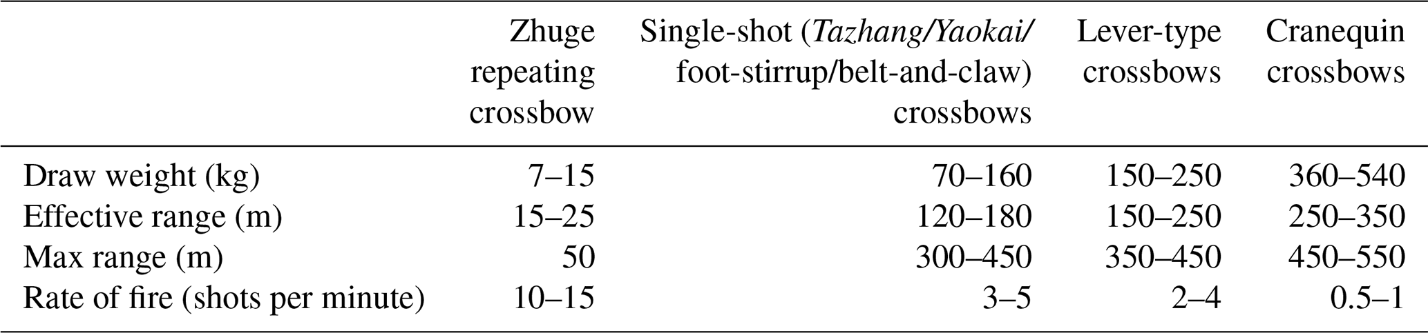
As can be seen from Table 4, although Chinese and Western single-shot crossbows differ structurally, they exhibit a remarkable convergence in performance by setting their draw force around the “limit of an individual's full-body strength”. This range ensures that the bolt possesses sufficient kinetic energy to penetrate contemporary mainstream armor, without making the reloading process unacceptably slow. On the other hand, the Zhuge repeating crossbow and the lever-type or cranequin crossbows represent developments toward two opposite extremes.
Through the above cross-civilizational discussion, it is evident that although both Chinese and Western military technological traditions independently developed single-shot, human-powered crossbows for infantry use – reflecting their commonalities in ergonomics and tactical constraints – their specialized designs exhibit significant technological divergence. The Zhuge repeating crossbow, lever-type crossbow, and cranequin crossbow are, in essence, engineered responses to specific tactical contexts. Their technical differences are rooted in distinct material cultures, craft systems, and battlefield environmental demands. These mechanical devices not only demonstrate the ingenious concepts and exceptional wisdom of ancient technology in overcoming human physiological limitations but also provide valuable cases for reinterpretation and theoretical examination from the perspective of modern mechanical engineering.
Crossbows were crucial for warfare in both ancient Eastern and Western societies and represent an evolution from traditional bows. During the shooting process, the topological structure of a crossbow changes, classifying it as a variable-topology mechanism. This study reviewed the historical development of Eastern and Western crossbows and analyzed the structural changes that occur throughout the shooting process. The earliest crossbows in ancient China date back to the 6th century BCE, and by the 2nd century CE, records already documented crossbows capable of rapid, consecutive firing. In Europe, large crossbows had already been developed in ancient Rome, and by the 14th–15th centuries, lever- and gear-based cocking mechanisms were introduced to draw high-strength bowstrings efficiently. This study applied graphical representation to examine the topological variability of crossbows, analyzed their degrees of freedom and constrained motions during shooting, and ultimately illustrated the shooting process using 3D computer models. Through the exploration of crossbows in the East and West, these mechanical devices not only demonstrate the ingenuity and wisdom of the ancients, but also provide valuable case studies for modern mechanical design.
All code included in this study is available upon request to the corresponding author.
All data included in this study are available upon request to the corresponding author.
All authors made contributions to the study of historical crossbows. ZRW and KHH were the lead authors and provided the material of the crossbows. YZ directed the analysis of the model represented in the paper. ZRW structured the paper. CYL provided reviews of the paper. KHH made contributions to the presentation approaches for the crossbows.
The contact author has declared that none of the authors has any competing interests.
Publisher's note: Copernicus Publications remains neutral with regard to jurisdictional claims made in the text, published maps, institutional affiliations, or any other geographical representation in this paper. The authors bear the ultimate responsibility for providing appropriate place names. Views expressed in the text are those of the authors and do not necessarily reflect the views of the publisher.
The authors wish to express their gratitude to the National Science and Technology Council, Taipei, Taiwan, for providing financial support.
This research has been supported by the National Science and Technology Council, Taipei, Taiwan, provided under NSTC grant no. 114-2410-H-359-003 and Humanities and Social Science Fund of Ministry of Education (Beijing, China) under grant no. 21YJC760110.
This paper was edited by Liangliang Cheng and reviewed by two anonymous referees.
Chen, S.: The Records of the Three Kingdoms, Chung Hwa Book Company, Taipei, ISBN: 9789865512156, 2020 (in Chinese).
Chen, Y. J.: A Study on the Double-Bolt Repeating Crossbow Unearthed from Chu Tombs in Jiangling, Cultural Relics, 5, 89–96, 1990 (in Chinese).
Ford, R. and Grant, R. G.: Weapon: A Visual History of Arms and Armor, Dorling Kindersley Publishing, ISBN: 9780756622107, 2006.
Gorman, S.: The Technological Development of the Bow and the Crossbow in the Later Middle Ages, PhD thesis, Trinity College Dublin, http://hdl.handle.net/2262/77397 (last access: 23 March 2026), 2016.
Hsiao, K. H.: Structural Synthesis of Ancient Chinese Original Crossbow, T. Can. Soc. Mech. Eng., 37, 259–271, https://doi.org/10.1139/tcsme-2013-0016, 2013.
Hsiao, K. H. and Yan, H. S.: Mechanisms in Ancient Chinese Books with Illustrations, Springer, Switzerland, https://doi.org/10.1007/978-3-319-02009-9, 2014.
Loades, M.: The Crossbow, Osprey Publishing, ISBN: 9781472824608, 2018.
Mao, T. Y.: Treatise on Armament, 1st edn., Hainan Press, ISBN: 9787806458693, 2001 (in Chinese).
McNab, C.: A History of the World in 100 Weapons, Osprey Publishing, Oxford, UK, ISBN: 9781435141483, 2012.
Needham, J.: Science and Civilisation in China, Vol. 5, Part 6, Cambridge University Press, ISBN: 9780521057998, 1954.
Payne-Gallwey, R.: The Book of the Crossbow, Dover Publications, ISBN: 9780486287201, 1995.
Sun, T.: The Art of War, 1st edn., Ixia Press, ISBN: 9780486832944, 2019.
Tsai, L. W.: Mechanism Design: Enumeration of Kinematic Structures According to Function, CRC Press, https://doi.org/10.1201/9780367802790, 2000.
Yan, H. S.: Creative Design of Mechanical Devices, Springer, Singapore, ISBN: 9789813083578, 1998.
Yan, H. S.: Mechanisms: Theory and Applications, McGraw-Hill, ISBN: 9789814660006, 2016.
You, Z. H.: The Mechanical Technology and Combat Characteristics of the Continuously Shooting Crossbow in Ancient China, in: Proceedings of the First International Conference on the History of Chinese and Japanese Mechanical Technology, Beijing, China, 12–14 October 1998, 257–263, 1998 (in Chinese).
Zhang, C. H., You, Z. H., Wu, Z. Z., and Liu, Y. L.: History of Inventions in Chinese Mechanical Engineering, 2nd edn., Tsinghua University Press, ISBN: 9787302091004, 2004 (in Chinese).
- Abstract
- Introduction
- A brief history of early crossbow development
- Topological structure and graphical representation
- Structural analysis
- A cross-cultural comparison of ancient crossbows
- Conclusions
- Code availability
- Data availability
- Author contributions
- Competing interests
- Disclaimer
- Acknowledgements
- Financial support
- Review statement
- References