the Creative Commons Attribution 4.0 License.
the Creative Commons Attribution 4.0 License.
 | 20 Mar 2026
Surface quality and process optimization in rotary ultrasonic-assisted drilling of carbon-fiber-reinforced plastics
Lingzhi Luo
Fuxian Zhu
Liuyang Duan
Fengling Zhao
Zhen Zhang
To address the issue of exit delamination and burr defects during the drilling of carbon-fiber-reinforced plastics (CFRPs), this study employs rotary ultrasonic-assisted drilling (RUD) technology. A three-factor, three-level drilling experiment was designed using the Box–Behnken method to analyze the morphology of drilling-induced defects. Based on response surface methodology (RSM), the influence of process parameters on exit defects was quantitatively evaluated, the interactions among process parameters were investigated, and the RUD parameters were optimized. The results indicate that delamination damage and burr defects are prone to occur at the drill exit. Increasing the spindle speed (7000 r min−1) effectively suppresses delamination, while reducing the feed rate (30 mm min−1) and using a coarse-grit tool (60 grits) significantly minimize fiber tearing and burr formation. The optimal parameter combination (7000 r min−1, 30 mm min−1, 60-grit tool), obtained through multi-objective optimization, was experimentally validated. The delamination factor and burr height coefficient were reduced to 1.047 and 0.016, respectively, consistent with the model predictions. This study provides a process strategy for high-precision drilling of CFRP that enables synergistic control of multiple defects.
- Article
(10207 KB) - Full-text XML
- BibTeX
- EndNote


Carbon-fiber-reinforced plastics (CFRPs) are widely used in the fields of aerospace and transportation due to their excellent properties (Barile et al., 2022; Papa et al., 2019). Drilling is one of the common machining processes used to achieve assembly connections between CFRP components (Xu et al., 2023). Owing to the laminated structure, anisotropy, and long-fiber reinforcement characteristics of CFRP laminates, major defects such as delamination damage, burrs, and fiber pull-out tend to occur at the exit side during drilling. These defects not only reduce the assembly tolerance and surface quality of the holes but also compromise the mechanical performance and load-bearing capacity of the overall structure. Therefore, it is necessary to optimize the drilling process to suppress these defects (Xu et al., 2022; Zadafiya et al., 2021; Zhu et al., 2022).
To enhance the quality and efficiency of drilling CFRP laminates, researchers have developed improvements upon traditional drill bits primarily by optimizing structural parameters such as the nose edge (Lazar and Xirouchakis, 2011), point angle (Durão et al., 2010), stepped cutting edge (Xia and Mahdavian, 2005), or double-point angle (Henerichs et al., 2015). These modifications aim to control the axial force below the critical threshold, thereby suppressing exit-side delamination damage. Building on this, Priarone et al. (2017) investigated the performance of a coreless diamond core drill based on the concept of “drilling by grinding”. It was concluded that this approach significantly reduces axial force and temperature, effectively mitigating machining damage in composites; however, its machining efficiency remains relatively low. Studies by Lv et al. (2021) and Lotfi et al. (2022) indicated that rotary ultrasonic-assisted drilling (RUD) enables high-frequency vibration of the tool during grinding, which periodically removes material and alters the material removal process. The studies by these two researchers primarily focus on the advantages of ultrasonic-assisted machining, with a relatively singular research objective. However, in actual machining processes, optimizing and improving a single defect make it challenging to identify the optimal process parameters. Shard et al. (2023) conducted ultrasonic-assisted drilling experiments on CFRP using a twist drill and a diamond core drill. The results demonstrated that under ultrasonic assistance, the use of a diamond core drill significantly reduced delamination defects compared to non-ultrasonic drilling. Similarly, Geng et al. (2020) performed ultrasonic-assisted drilling experiments on CFRP with a diamond core drill and found that the hole quality at both entry and exit sides was superior with ultrasonic assistance, leading to better overall hole machining quality. Evidently, compared with conventional drilling processes, RUD offers distinct advantages, including reduced axial force, lower grinding temperature, improved chip evacuation, suppressed delamination, better surface roughness, and higher drilling accuracy.
On the other hand, the drilling process itself is a critical factor influencing machining quality. Scholars have conducted experimental studies on drilling processes to investigate their effects on drilling-induced defects, explore the underlying mechanisms of defect formation, and further enhance the quality of holes in CFRP composites by employing intelligent optimization algorithms to optimize process parameters (Cao et al., 2022; Xu et al., 2021; Zhang et al., 2020). Mudhukrishnan et al. (2019) investigated the influence of drilling parameters on exit delamination in CFRP composites based on a full factorial design. A correlation model between drilling parameters and responses was established, revealing that the delamination factor increases with feed rate and decreases with spindle speed. Liu et al. (2023) employed an orthogonal experimental design to comparatively analyze exit burr formation under three processes: conventional drilling (CD), ultrasonic-assisted drilling (UAD), and ultrasonic-assisted peck drilling (UAPD), across varying parameters. Shard et al. (2023) employed rotary ultrasonic-assisted drilling (RUD) to machine CFRP composites and conducted a comparative analysis with rotary drilling and conventional drilling. Experiments were performed to study the influence of different drilling parameters on cutting force, temperature, torque, surface roughness, material removal rate (MRR), and micro-cracks at the hole edge. Slimane et al. (2019) experimentally investigated the combined effects of vibration amplitude, tool rotation speed, and feed rate on cutting forces during the rotary ultrasonic machining (RUM) of CFRP composites. Optimal cutting force values were identified, leading to the optimization of process parameters. Zhang et al. (2023) studied the effects of process parameters in ultrasonic-vibration-assisted helical grinding (UVHG) on hole wall surface roughness and exit defects. The results demonstrated the significant effectiveness of the UVHG method in reducing surface roughness and suppressing exit defects. A process parameter optimization model was developed, and the multi-objective optimization problem was solved using the NSGA-II algorithm to obtain the optimal parameter set.
Existing research indicates that the drilling quality and efficiency of carbon-fiber-reinforced plastic (CFRP) composites are simultaneously influenced by tool geometry and machining parameters. Process optimization based on machining experiments can effectively reduce thrust force, minimize defects, and enhance hole quality (Sanda et al., 2016; Wang et al., 2023). Current research in ultrasonic-vibration-assisted grinding drilling primarily focuses on the influence of processing parameters on a single type of defect under ultrasonic assistance. However, drilling defects in CFRP composites are diverse. Studies on the improvement mechanisms for a single defect struggle to achieve the optimal selection of both tool structure and machining parameters. Therefore, distinguishing itself from existing research, this paper not only introduces the tool grit size as a key variable into the response surface methodology (RSM) model alongside spindle speed and feed rate but also employs a three-factor, three-level Box–Behnken experimental design. This approach quantitatively evaluates the effects of various parameters and their interactions on two types of defects: exit delamination and burrs. With the objective of minimizing multiple defects, RSM is utilized to achieve the multi-objective optimization of both the grit size of the diamond core drill and the machining parameters, aiming to identify superior machining process parameters.
2.1 Experimental sample
Square CFRP laminates are used as the drilling specimens in this experiment. The upper and lower surface layers of the laminates consist of a 0 and 90° carbon fiber plain weave, while the internal structure comprises 0 and 90° cross-ply carbon fiber layers, with a total of 33 plies. The carbon fiber prepreg is first cut into 300 × 300 mm squares. The cut prepreg sheets are then laid into a mold in a specific sequence of 0 and 90° cross-ply orientation. Subsequently, the mold is closed and cured in a hot press. Finally, the cured panel is demolded, trimmed, and cut into the 100 × 100 mm CFRP workpieces used in this study, with a final specimen thickness of 5 mm.
2.2 Experimental equipment
The hole-making equipment used was a Chuang Sheng Teer vertical machining center. The work travel of the X, Y, and Z axes of this machine tool is 800 × 500 × 550 mm, with a table area of 500 × 1000 mm2. The spindle speed can reach up to 12 000 r min−1. The experiment employed an ultrasonic vibration device developed by the Nanjing University of Aeronautics and Astronautics, which consists of three parts: a generator, a primary coil, and a tool holder. The coil was fastened to the spindle with screws; the generator and the primary coil were connected via a power cable. The tool used in the experiment was an electroplated diamond core drill, whose structure comprises a drill head, chip flutes, and a shank. The base material is tool steel, and the drill head is bonded with diamond abrasive grains through an electroplating process. The tool length is 50 mm, with an outer diameter of the drill head of 6 mm and an inner diameter of 4.5 mm. The abrasive grain size is 250 µm. The tool was mounted onto the ultrasonic tool holder using a collet chuck and a locking nut. The machining setup is shown in Fig. 1.
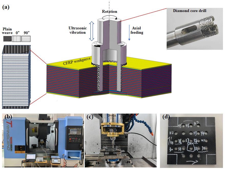
Figure 1Experimental setup. (a) Schematic of the experimental principle, (b) machining machine tool, (c) ultrasonic vibration device, and (d) machined specimen.
2.3 Testing methods
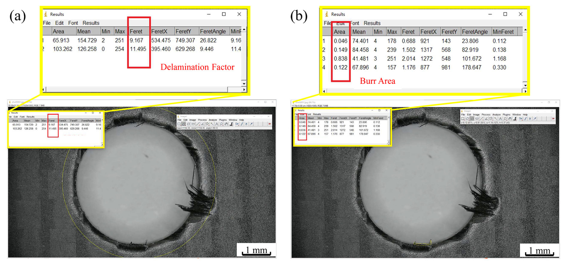
The experiment employed a scanning electron microscope (SEM) to observe microscopic defects on the hole's inner wall and utilized a HIROX RH-2000 3D video microscope to examine machining defects at the entrance and exit of the CFRP hole. The size of the damage zones was precisely measured through microscopic images.
Existing research indicates that larger defects on the hole's inner wall are primarily concentrated at the hole's entrance and exit, manifesting mainly as delamination defects and burr defects, which require quantitative analysis (Luo et al., 2019; Xu et al., 2020).
The quantitative evaluation method for delamination defects in drilling of CFRP laminates is as follows:
In the equations, Fd represents the delamination factor, Dmax is the maximum defect diameter, and D is the preset hole diameter.
The burr area is adopted to evaluate the burr defect in the drilling of CFRP laminates, and the expression is given as follows:
In the equations, Cb represents the burr factor, Ab is the total burr area, and An is the predesigned area of the hole. The measurement method is shown in Fig. 2.
2.4 Design of experiments based on response surface methodology
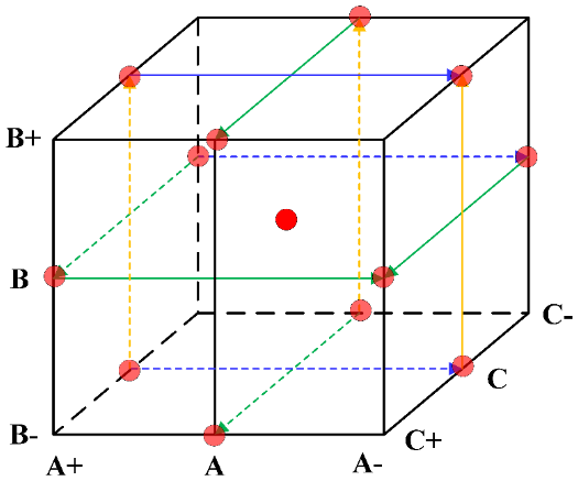
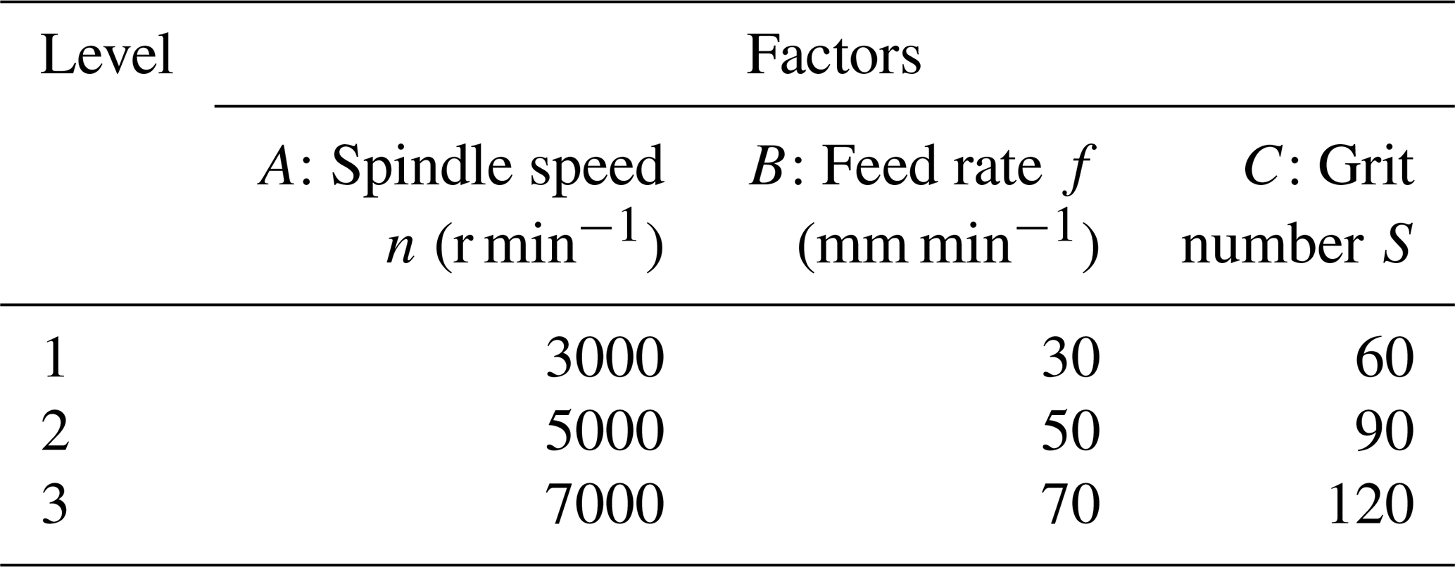
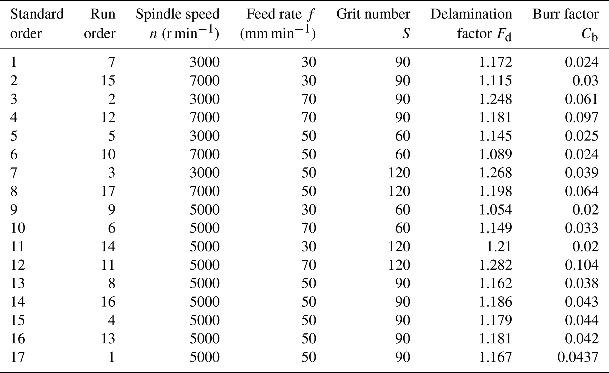
The core concept of response surface methodology (RSM) is to establish an RSM function Y=f(x), which approximates the mapping function y=f(x) with maximum accuracy (Box and Wilson, 1951). RSM employs various experimental design models, such as central composite design (CCD), Box–Behnken design (BBD), and uniform design. Among these, the Box–Behnken design (BBD) is preferred due to its spherical structure (Spahiu et al., 2022), where design points are located on a sphere of a fixed radius, corresponding to the midpoints of the edges of a cube. This design offers greater efficiency in the number of required experimental runs while demonstrating higher accuracy in evaluating the nonlinear effects of factors. The design principle is illustrated in Fig. 3, where A denotes the spindle speed, B represents the feed rate, and C indicates the tool grit number. Based on relevant references (Zhu et al., 2025) and the typical operating range of diamond core drills, the experimental levels are shown in Table 1. In this study, a three-factor, three-level experimental scheme was designed using the BBD approach, with five replicated experiments at the center point. Each experimental group was repeated three times, and the average value was taken. To ensure consistency in temperature, tool wear, and vibration stability, all experiments were conducted under uniform environmental conditions. A new tool was used for each experimental group, and the ultrasonic vibration frequency and amplitude were fixed at 23.2 kHz and 7 µm, respectively. The experimental order was randomized to avoid noise interference. The BBD experimental parameters are listed in Table 2.
An RSM model can be established based on the response results, with the following general form:
In the equations, Y is the response variable; n is the number of design variables (n = 3); β0 is the regression intercept; βi, βii, and βij are the linear coefficient, quadratic coefficient, and interaction coefficient, respectively; and ε is the normal random error.
An analysis of variance (ANOVA) of the experimental results was conducted using Design-Expert software. The significance of the constant term, linear terms, quadratic terms, and interaction terms in the regression equation was evaluated. The reliability of the established model is demonstrated by a significance test with P > 0.05. The goodness of fit of the model is examined using the coefficient of determination R2. R2 has an inherent drawback in that its value tends to increase with the number of independent variables; therefore, it is adjusted to the adjusted . The predictive capability of the model for new data is assessed by the predicted R2 pred. These three metrics vary within the range [0, 1]. A value of closer to 1 indicates a better fit of the model to the current data, while a value of closer to 1 signifies stronger predictive ability for new data (Jian et al., 2023). Their expressions are as follows:
In the equations, SSE is the sum of squared errors (the sum of squared differences between the experimental values and the model-predicted values), SST is the total sum of squares (the sum of squared differences between the experimental values and the mean of experimental values), n is the number of samples, p is the number of independent variables, y(i) is the experimental value with the ith observation deleted, and is the predicted value with the ith observation deleted.
Subsequently, residual plots are generated using the experimental design software for diagnostic purposes. The goodness of fit between the model and the data is evaluated by analyzing the absolute values of the residuals. Standardized residuals are commonly employed to eliminate the influence of measurement units; however, they fail to eliminate the impact of K–T transformation. This study adopts studentized deleted residuals as a replacement for standardized residuals, which provides a more intuitive assessment of whether the error terms conform to a normal distribution and contributes to the optimization of the linear regression model (Jones and Nachtsheim, 2017). Its expression is as follows:
In the equations, ti denotes the studentized deleted residual for the ith observation, ei represents the residual, hii is the diagonal element of the K–T transformation matrix , and SSE(−i) indicates the sum of squared errors calculated after deleting the ith observation, based on the remaining n−1 data points.
3.1 Analysis of drilling-induced defects
Figure 4 shows the surface morphology at the entrance of a hole drilled in CFRP using a 60-grit tool. The entrance machining phase, which is when the tool is about to enter the workpiece, is primarily characterized by the cutting action of the tool's bottom-end face on the material. This phase persists until the tool breaks through the surface layer and enters the interior of the material. At this stage, as the tool has just entered the material, the workpiece material is sufficiently supported from below, preventing delamination and resulting only in tearing damage on the CFRP surface. Furthermore, it can be observed that as the feed rate increases, the quality at the entrance of the CFRP hole gradually improves, with defects significantly reduced.
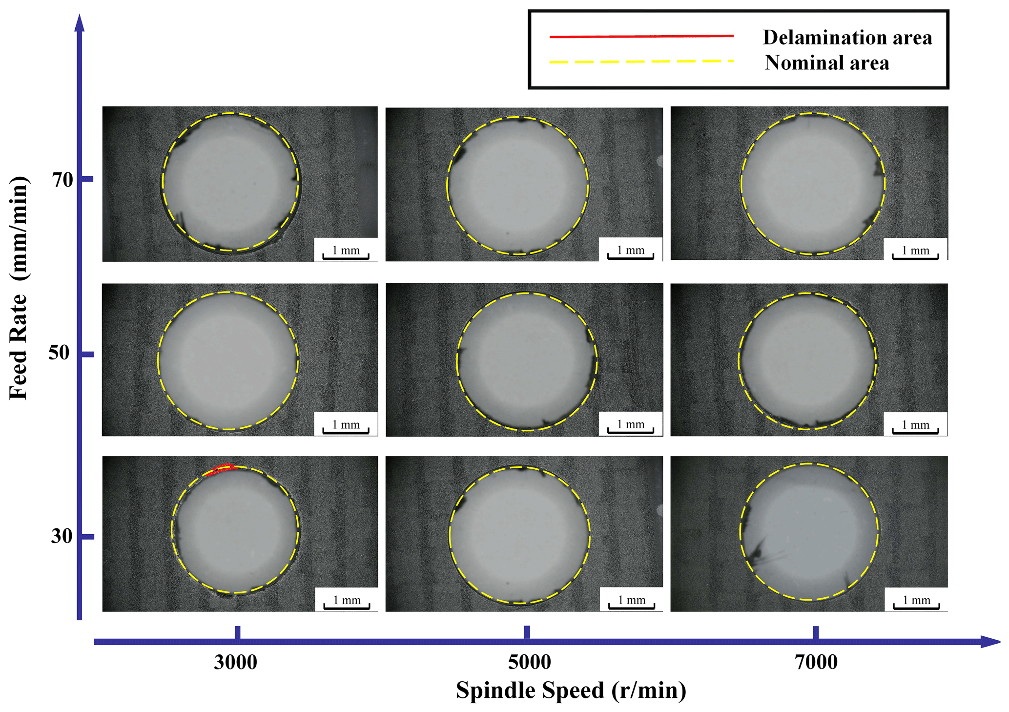
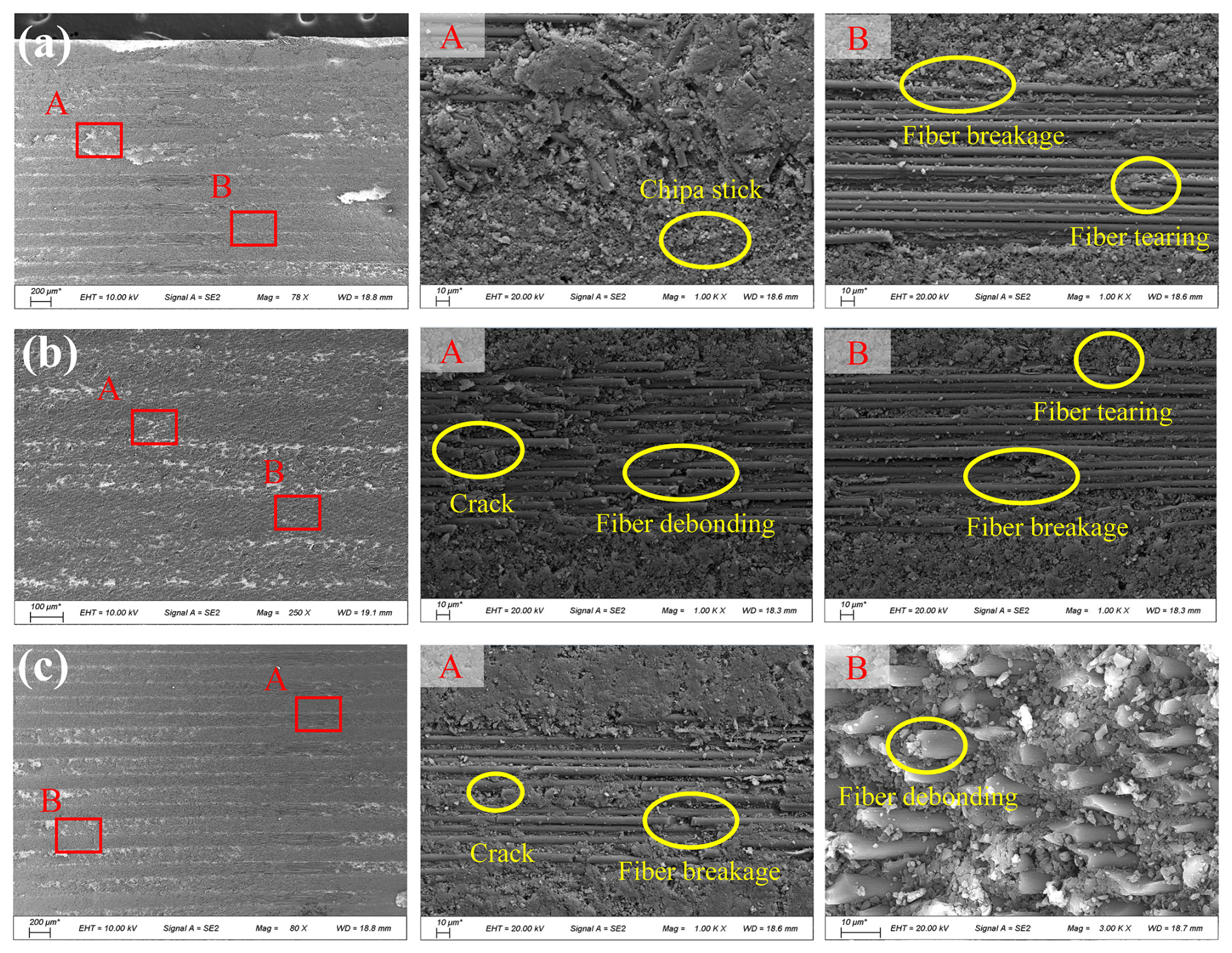
Figure 5SEM morphology of hole wall processed by RUD (a) 3000 r min−1, (b) 5000 r min−1, and (c) 7000 r min−1.
Figure 5 shows SEM images of the hole wall morphology in CFRP machined with a 60-grit tool at spindle speeds n of 3000, 5000, and 7000 r min−1 and a feed rate f of 30 mm min−1. It can be observed that due to the sufficient thickness of the undrilled portion, the composite layers of the workpiece remain adequately supported, preventing delamination damage. When n increases from 3000 to 7000 r min−1, defects such as matrix loss and surface voids are reduced to some extent. This is because a higher cutting speed reduces the axial force, and material removal is primarily caused by bending fracture. At lower spindle speeds, higher axial forces lead to more severe fiber bending, thereby exacerbating fiber debonding (Du et al., 2023). As revealed by the high-magnification SEM image in Fig. 5a, chip adhesion is present on the inner wall of the hole. This is mainly attributed to the high temperatures generated during processing (approaching or exceeding the material's softening point), which cause further softening of the matrix in the thermosetting CF/epoxy composite. When the polymer matrix is in a viscous state, the shear force applied by the tool edge readily aligns the polymer chains along the strain direction, consequently forming a matrix coating and chip adhesion (Ge et al., 2023).
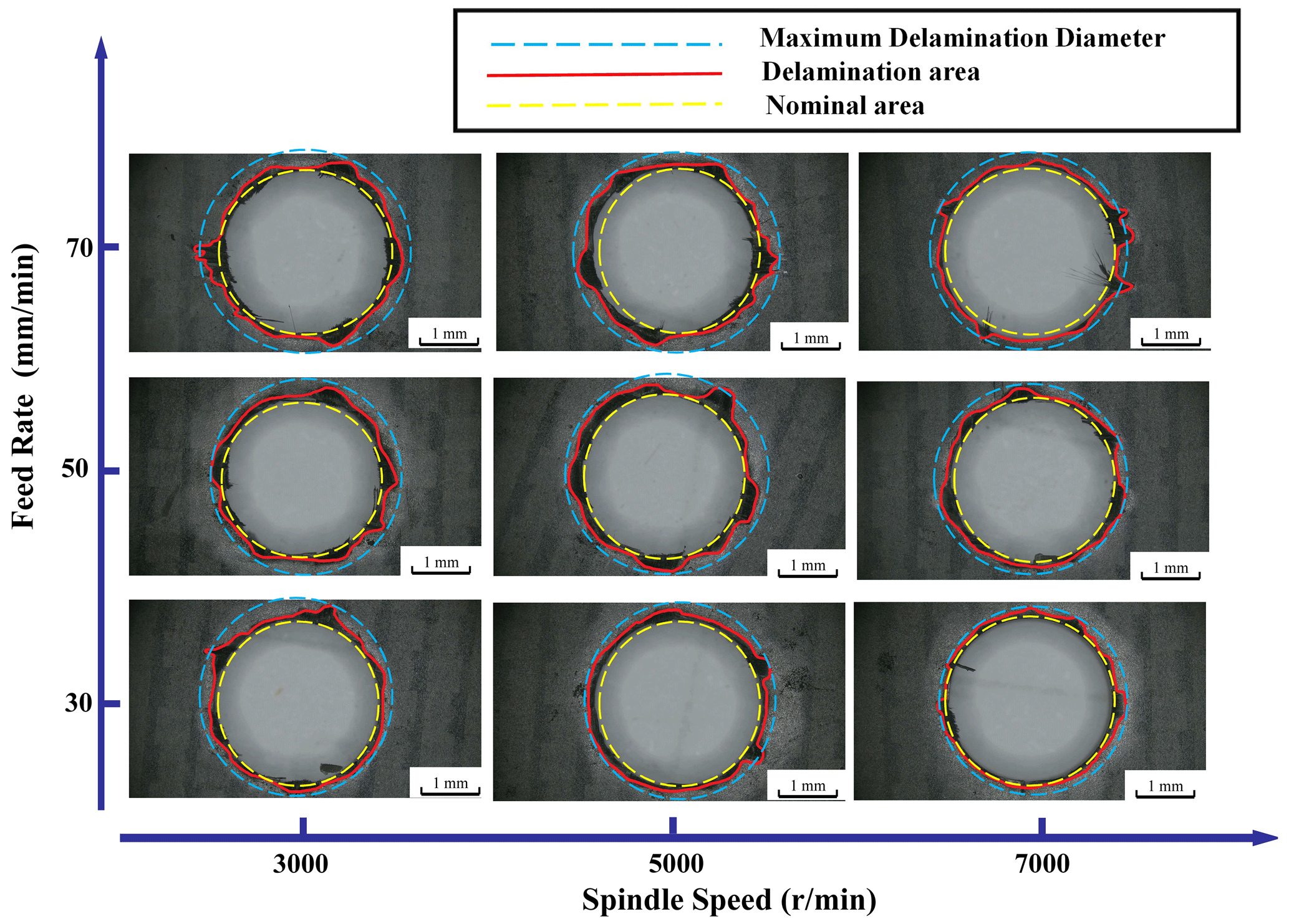
Figure 6 shows the surface morphology at the exit of a hole drilled in CFRP using a 60-grit tool. It can be observed that the exit region exhibits a large tearing area and an increased delamination diameter. This is attributed to the fact that during tool exit, the unsupported bottom layer experiences tensile stress induced by bending, and the axial grinding force from the tool exceeds the interlaminar bonding strength of the undrilled material (Zhang et al., 2024; Zhu et al., 2025), resulting in interlaminar delamination. Additionally, due to variations in the sharpness of abrasive cutting edges and reduced constraint on the fiber material, fibers cannot be completely severed, leading to the rotation of terminal fibers with the tool face and their instantaneous tearing, thereby forming defects such as burrs and torn fibers. Furthermore, the figure indicates that as the feed rate increases, the delamination factors at the CFRP hole exit show an increasing trend. This occurs because a higher feed rate elevates the axial force during drilling, which enhances the axial pushing effect at the hole exit, causing delamination damage in a thicker undrilled layer and resulting in more extensive fiber tearing (Geng et al., 2020). Conversely, as the spindle speed rises, the delamination factors at the exit decrease. This is because the increased spindle speed reduces the pushing effect at the exit, leading to delamination occurring in a thinner undrilled layer with lower interlaminar component strength, thereby mitigating exit delamination damage.
In summary, when utilizing the RUD drilling process, sufficient support is present beneath both the hole entrance and the hole wall in CFRP, making delamination damage less likely to occur. In contrast, during exit processing, the lack of adequate underlying support readily induces delamination damage. It can therefore be concluded that the damage is more severe at the exit. Consequently, subsequent research will focus specifically on the influencing factors at the exit region to optimize the overall drilling process parameters and achieve optimal hole quality.
3.2 Analysis of influencing factors on delamination factors
Within the process parameter range studied in this paper, a second-order model was established based on the Box–Behnken design (BBD) and expressed in the form of a second-order polynomial, as shown in Eq. (3). The correlation coefficients were computed using the least squares method and fitted to 17 sets of experimental data. After fitting, ANOVA was conducted to test the significance of each coefficient. Insignificant terms were eliminated, and the remaining coefficients were substituted back into the original model to obtain the second-order nonlinear fitting equation.
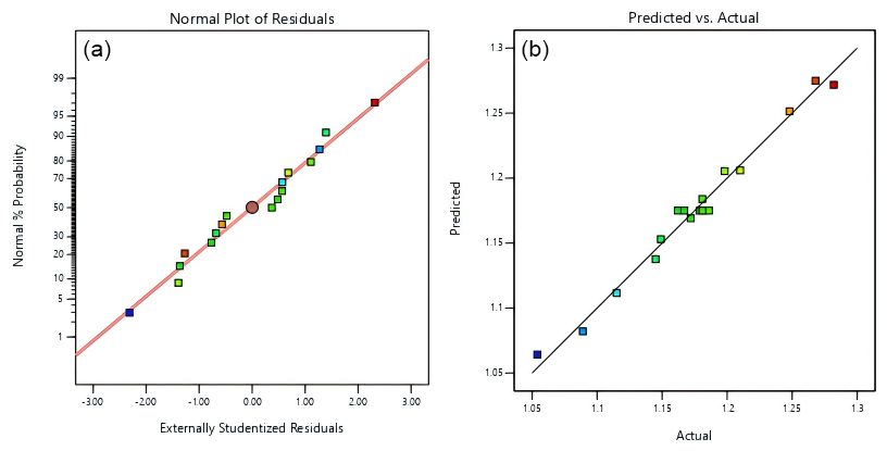
Figure 7Comparison between experimental and predicted results for delamination factors. (a) Normal probability plot of residuals, (b) experimental vs. predicted values.
Based on the experimental data, the second-order nonlinear fitting equation for the influence of process parameters on the exit delamination factor (Fd) in CFRP grinding drilling is given as follows:
Based on the fitted second-order nonlinear equation, a comparison plot between the experimental results and predicted results is shown in Fig. 7. As seen in Fig. 7a, the studentized deleted residuals of the exit delamination defect model for CFRP grinding drilling follow a normal distribution, indicating that the response values predicted by the proposed model are reliable without significant deviations. From Fig. 7b, it can be observed that all scattered points are distributed near the correlation line, meaning the abscissa and ordinate values of each point are close, which demonstrates high agreement between predicted and actual values. This confirms that the equation has a high goodness of fit and can effectively predict experimental results.
Table 3Analysis of variance (ANOVA) for the delamination defect model.
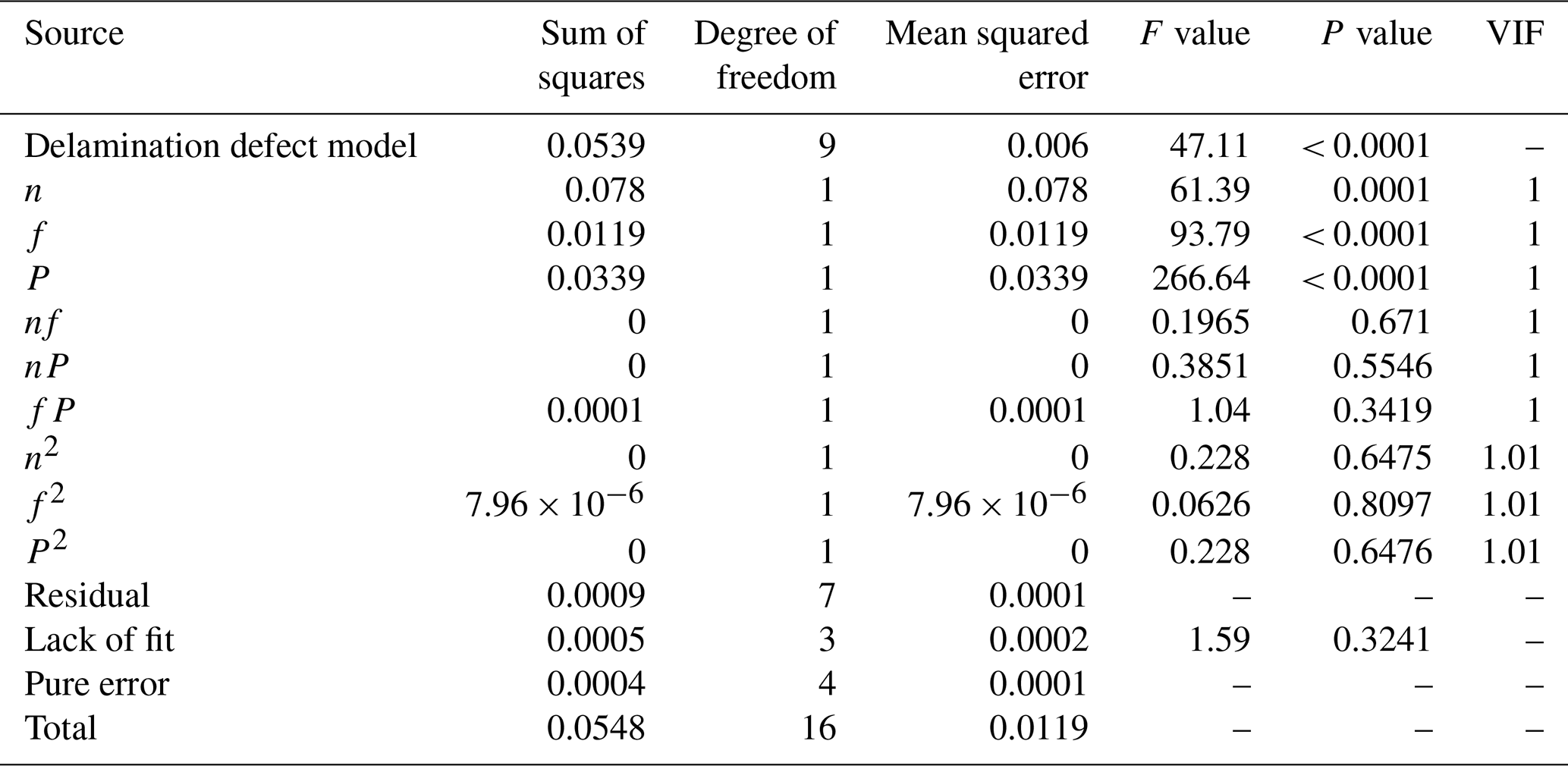
Table 3 presents the ANOVA results for the delamination defect model. The variance inflation factor (VIF) for each coefficient in the model falls between 1 and 1.01, which is well below the threshold of 5. This indicates that there is no significant multicollinearity among the independent variables, and the control of collinearity in the model is effective. The significance of the model depends on the F value (the ratio of the model's mean square to the residual mean square) and the P value. A larger F value and a smaller P value indicate a more significant effect. As can be seen from Table 3, the model's F value is 47.11, and the P value is less than 0.0001, indicating that the model is effective and highly significant. The lack-of-fit P value is 0.3241, which is greater than 0.05 and is not significant, further demonstrating the validity of the model. Furthermore, based on the P values, the contribution of the three main factors to the delamination factor can be evaluated. The spindle speed (n) has the least influence on delamination factors. Both the tool feed rate (f) and the tool grit number (S) have P values less than 0.0001, indicating that they exert a substantial and comparable influence on delamination factors. The influence of the interaction terms on delamination factors, in descending order, is . Analysis of the correlation coefficients shows that the R2 and values are 0.9838 and 0.9629, respectively, both close to 1, indicating a high correlation of the model. The value is 0.8470, and the difference between and is less than 0.2, demonstrating that the model has both a good fit and predictive ability, fully reflecting the rationality of the CFRP grinding drilling experiment. The adequate precision value (the ratio of the standard deviation of the predicted values to the model error) is 24.3448, which is greater than 4, indicating a reasonable model. The coefficient of variation (C.V. %) is 0.9595 %, which is less than 10 %, suggesting a high degree of reliability in the experimental design.
Response surface plots illustrating the pairwise interactions between spindle speed, tool feed rate, and tool grit number on the exit delamination factor during CFRP grinding drilling are generated using Design-Expert software.
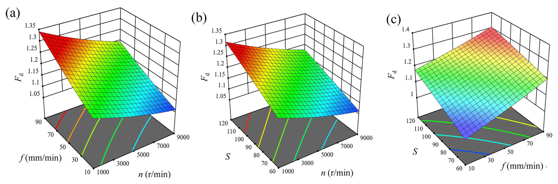
Figure 8Influence of interaction effects on delamination factors: (a) feed rate vs. spindle speed, (b) tool grit number vs. spindle speed, and (c) tool grit number vs. feed rate.
Figure 8a shows the interaction plot between spindle speed and tool feed rate at a fixed tool grit number. It can be observed from the figure that the delamination factor exhibits a negative correlation with spindle speed and a positive correlation with tool feed rate. Additionally, spindle speed and tool feed rate demonstrate an approximately linear relationship; however, their interaction contributes less than 5 % to the exit delamination factors, indicating that the interactive effect between spindle speed and tool feed rate has no significant influence on exit delamination. Furthermore, the results reveal that between spindle speed and feed rate, the feed rate exerts a greater influence on exit delamination. When the spindle speed is 3000 r min−1 and the feed rate increases from 30 to 70 mm min−1, the exit delamination factor increases by 6.5 %. Similarly, when the spindle speed is 7000 r min−1 and the feed rate increases from 30 to 70 mm min−1, the exit delamination factor rises by 5.9 %. Therefore, employing a lower feed rate is an effective approach to reduce exit delamination factors.
Figure 8b shows the interaction plot between spindle speed and tool grit number at a fixed feed rate. As illustrated, the exit delamination factor exhibits a negative correlation with spindle speed and a positive correlation with tool grit number. Furthermore, spindle speed and tool grit number demonstrate an approximately linear relationship, suggesting that their interaction has no significant influence on the exit delamination factor in CFRP. Moreover, comparative analysis indicates that the tool grit number exerts a greater influence on exit delamination factors than spindle speed. When the spindle speed is 3000 r min−1 and the tool grit number increases from 60 to 120, the exit delamination factor increases by 10.7 %. Similarly, when the spindle speed is 7000 r min−1 and the tool grit number increases from 60 to 120, the exit delamination factor rises by 10.01 %. Therefore, employing a lower-grit-number tool is an effective approach to reduce exit delamination factors in CFRP drilling.
Figure 8c shows the interaction plot between feed rate and tool grit number at a fixed spindle speed. As shown in the figure, the exit delamination factor exhibits a positive correlation with both feed rate and tool grit number. Additionally, the contour plot of feed rate and tool grit number shows significant curvature, indicating that their interaction has a substantial influence on the exit delamination factor in CFRP. Comparative analysis further reveals that feed rate exerts a greater influence on exit delamination factors than tool grit number. When the tool grit number is 60 and the feed rate increases from 30 to 70 mm min−1, the exit delamination factor increases by 9.01 %. Conversely, when the tool grit number is 120 and the feed rate increases from 30 to 70 mm min−1, the exit delamination factor rises by 6.01 %. Therefore, employing a lower-grit-number tool combined with reducing the feed rate is an effective strategy to minimize exit delamination factors in CFRP drilling.
Based on a comprehensive analysis of Fig. 8, it can be concluded that during ultrasonic-assisted grinding and drilling of CFRP, to minimize exit delamination factors, it is advisable to select a higher spindle speed, a lower tool feed rate, and a lower tool grit number within an appropriate range of process parameters. Furthermore, the tool feed rate and tool grit number exert a greater influence on delamination factors than spindle speed. Therefore, priority consideration should be given to optimizing these two factors.
3.3 Analysis of influencing factors on burr factor
Based on the experimental data, the second-order nonlinear fitting equation for the influence of process parameters on the exit burr factor (Cb) in CFRP grinding drilling is given as follows:
Based on the fitted second-order nonlinear equation, a comparison between experimental and predicted results is plotted in Fig. 9. As observed in Fig. 9a, the studentized deleted residuals of the exit burr defect model for CFRP grinding drilling follow a normal distribution, indicating no significant deviations in the response values predicted by the proposed model. From Fig. 9b, it can be seen that all scattered points are distributed near the correlation line, meaning the abscissa and ordinate values of each point are close, which demonstrates high agreement between predicted and actual values. This confirms that the equation exhibits a high goodness of fit and can effectively predict experimental results.
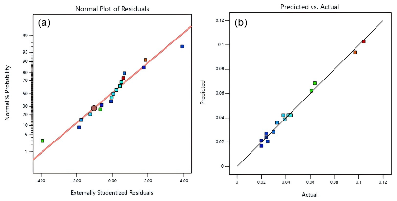
Figure 9Comparison between experimental and predicted results for burr factor. (a) Normal probability plot of residuals, (b) experimental vs. predicted values.
Table 4Analysis of variance (ANOVA) for the burr defect model.
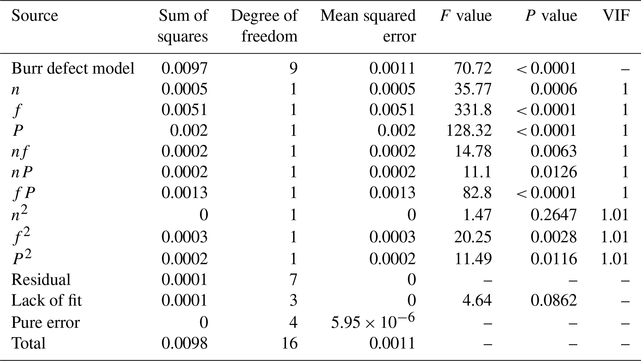
The ANOVA for the exit burr defect model in ultrasonic-assisted grinding and drilling of CFRP is presented in Table 4. The VIF for each coefficient in the model is 1 or 1.01, with all values being less than 5. This indicates that multicollinearity among the coefficients is well controlled. The model's F value is 70.72, and the P value is less than 0.0001, indicating that the model is highly significant and effective. Furthermore, the lack-of-fit P value is greater than 0.05, suggesting that the lack of fit is not significant, which confirms the high accuracy of the model and eliminates the need to consider higher-order terms such as cubic or above. Additionally, according to Table 4, among the three main factors, the tool feed rate and tool grit number exert a substantial influence on the exit burr factor, while the spindle speed has a relatively lower impact. The influence of interaction terms on the burr factor, in descending order, is . Analysis of the correlation coefficients reveals that the R2 and values are 0.9838 and 0.9629, respectively, both close to 1, indicating a high correlation of the model. The value is 0.8470, and the difference between and is less than 0.2, demonstrating that the experimental design and burr defect model adequately reflect the rationality of the CFRP grinding drilling experiment. The adequate precision value is 24.3448, which is greater than 4, indicating a reasonable model. The coefficient of variation (C.V. %) is 0.9595 %, less than 10 %, suggesting high reliability of the experimental design. Therefore, the burr defect model meets all validation criteria, and the regression equation exhibits an excellent fit.
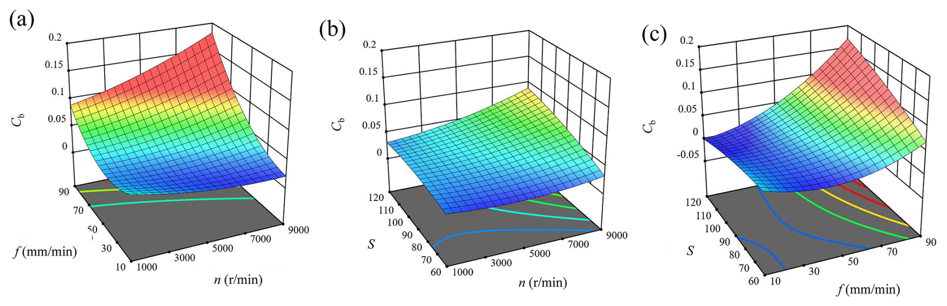
Figure 10Influence of interaction effects on burr factors. (a) Feed rate vs. spindle speed, (b) tool grit number vs. spindle speed, and (c) tool grit number vs. feed rate.
Meanwhile, response surface plots illustrating the pairwise interactions between spindle speed, tool feed rate, and tool grit number on the exit burr area during CFRP grinding drilling are generated using Design-Expert software. Figure 10a shows the interaction plot between spindle speed and tool feed rate. It can be observed from the figure that the burr factor exhibits a positive correlation with both spindle speed and tool feed rate. Regarding the extent of their influence on the exit burr area, the feed rate exerts a greater impact than the spindle speed. When the spindle speed is 3000 r min−1 and the feed rate increases from 30 to 70 mm min−1, the exit burr area increases by approximately 2.54. Similarly, when the spindle speed is 7000 r min−1 and the feed rate increases from 30 to 70 mm min−1, the exit burr area rises by approximately 3.23. Therefore, employing a lower feed rate is an effective strategy to reduce exit burr defects.
Figure 10b shows the interaction plot between spindle speed and tool grit number. It can be observed that the exit burr area exhibits a positive correlation with both spindle speed and tool grit number. Additionally, the interaction between tool grit number and spindle speed has a relatively insignificant influence on the exit burr area of CFRP. Between these two factors, the tool grit number exerts a greater influence on the exit burr area than the spindle speed. When the spindle speed is 3000 r min−1 and the tool grit number increases from 60 to 120, the exit burr area increases by approximately 1.56. Similarly, when the spindle speed is 7000 r min−1 and the tool grit number increases from 60 to 120, the exit burr area rises by approximately 2.67. Therefore, employing a tool with a lower grit number is an effective approach to reduce the exit burr area in CFRP drilling.
Figure 10c shows the interaction plot between feed rate and tool grit number. It can be observed that the exit burr area exhibits a positive correlation with both feed rate and tool grit number. Additionally, the contour plot of feed rate and tool grit number shows significant curvature, indicating that their interaction has a substantial influence on the exit burr area of CFRP. Between these two factors, the feed rate exerts a greater influence on the exit burr area than the tool grit number. When the tool grit number is 60 and the feed rate increases from 30 to 70 mm min−1, the exit burr area increases by approximately 1.65. Conversely, when the tool grit number is 120 and the feed rate increases from 30 to 70 mm min−1, the exit burr area rises by approximately 5.2. Therefore, employing a tool with a lower grit number combined with reducing the feed rate is an effective strategy to minimize the exit burr area in CFRP drilling.
Based on a comprehensive analysis of Fig. 10, it can be concluded that although a positive correlation exists between spindle speed and burr area within a very limited range, the overall trend indicates that a higher spindle speed results in a smaller exit burr area in CFRP. Therefore, during ultrasonic-assisted grinding and drilling of CFRP, to minimize the exit burr area, it is advisable to select a higher spindle speed, a lower tool feed rate, and a lower tool grit number within an appropriate range of process parameters. Furthermore, the tool feed rate and tool grit number exert a greater influence on the burr area than the spindle speed. Hence, priority consideration should be given to optimizing these two factors.
3.4 Multi-objective optimization and experimental verification
3.4.1 Multi-objective response optimization
Currently, research on improving the drilling quality of carbon-fiber-reinforced polymer predominantly focuses on optimizing single-performance metrics. However, in practical operations, defects such as delamination and burrs often occur simultaneously. Given that the optimal combination of process parameters varies for different types of defects, single-objective optimization strategies struggle to comprehensively reflect the combined effects of these defects. Therefore, it is necessary to shift towards simultaneous multi-objective parameter optimization. With the objectives of minimizing both delamination and burr defects, and considering spindle speed, tool feed rate, and tool grit number as variables, the multi-objective optimization model for process parameters in ultrasonic-assisted grinding and drilling of CFRP is established as follows:
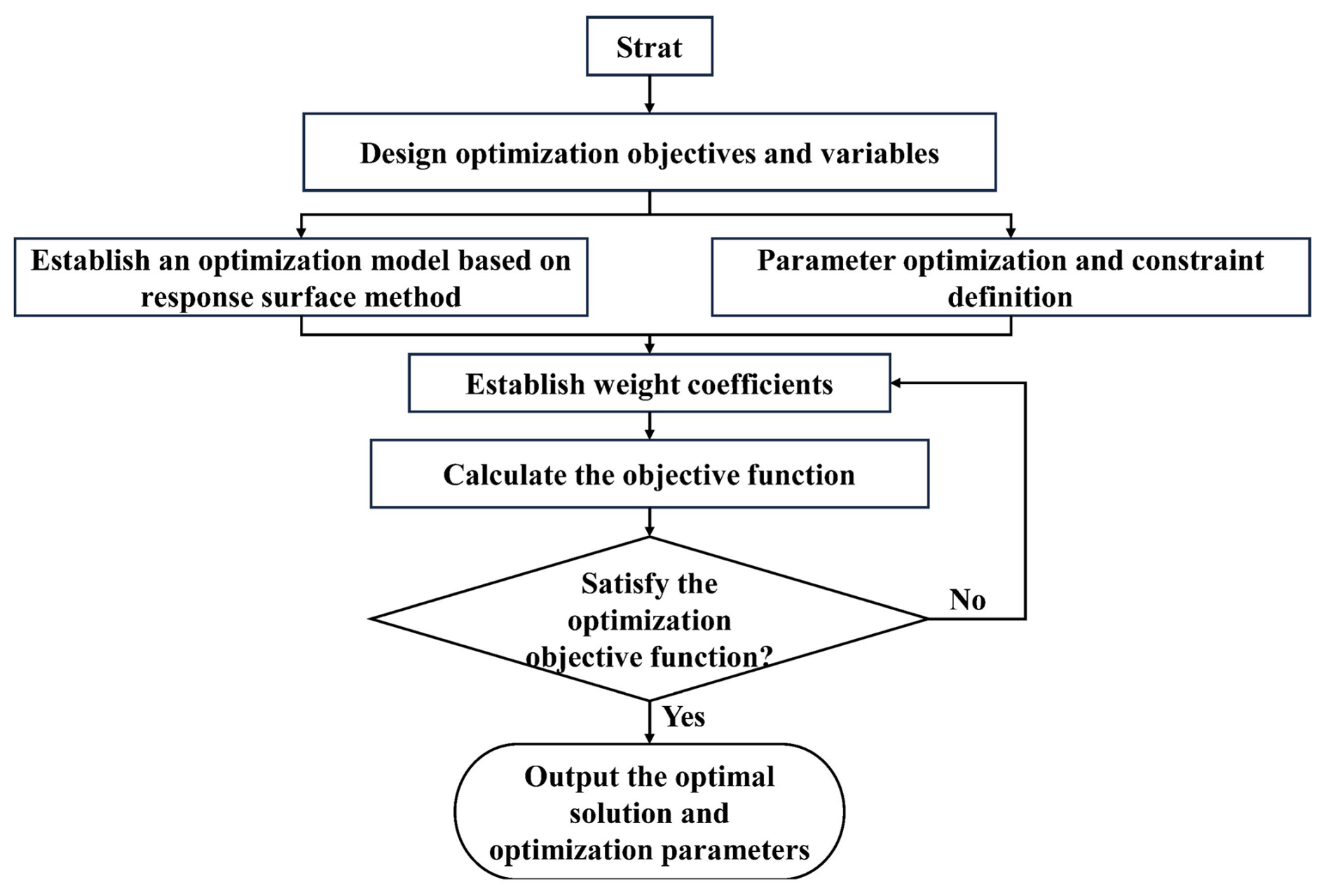
Design-Expert software was employed to solve the response surface model. Given the inherent compatibility between the desirability function approach and response surface methodology, coupled with the low computational cost of the desirability function method – which is well suited for the relatively limited number of variables in this study – the desirability function method was applied to solve the model. This enabled the optimization of process parameters for ultrasonic-assisted grinding and drilling of carbon-fiber-reinforced polymer composites. Specifically, a nonlinear regression model incorporating delamination and burr factors was first established for CFRP drilling process parameters within a defined range. Subsequently, a multi-objective optimization technique was utilized to construct a comprehensive defect evaluation system and identify the optimal configuration of process parameters. The procedure for establishing the multi-objective machining process parameter optimization model is illustrated in Fig. 11.
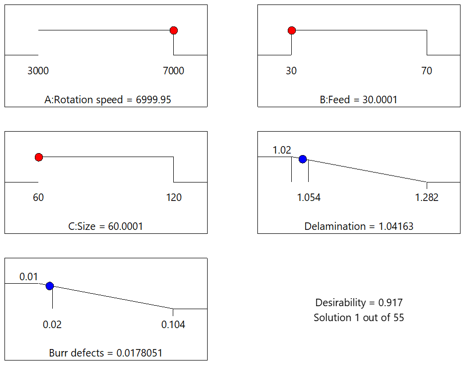
Figure 12 presents the multi-objective optimization results integrating both exit delamination defects and burr defects. It can be observed that when the spindle speed is 6999.95 r min−1, the tool feed rate is 30.0001 mm min−1, and the tool grit number is 60.0001 grit, the exit delamination factor of the CFRP hole reaches its minimum value of 1.0416, while the burr coefficient achieves its minimum value of 0.0178. The desirability of the model is 0.917, approaching 1.0, indicating that the optimization results of the multi-objective model exhibit high accuracy.
3.4.2 Parameter optimization and result validation
By integrating single-objective and multi-objective optimization models and considering experimental conditions and practical constraints in the drilling process, the optimized combination of process parameters is determined as follows: spindle speed of 7000 r min−1, feed rate of 30 mm min−1, and tool grit number of 60. The CFRP ultrasonic-assisted grinding and drilling experiments are conducted using this parameter set. To minimize experimental errors, three replicate trials are performed under this parameter combination, and the experimental results are averaged. Table 5 presents magnified images of the hole exit from the three experiments under this parameter set, along with quantitative analysis data of exit delamination and burr defects.
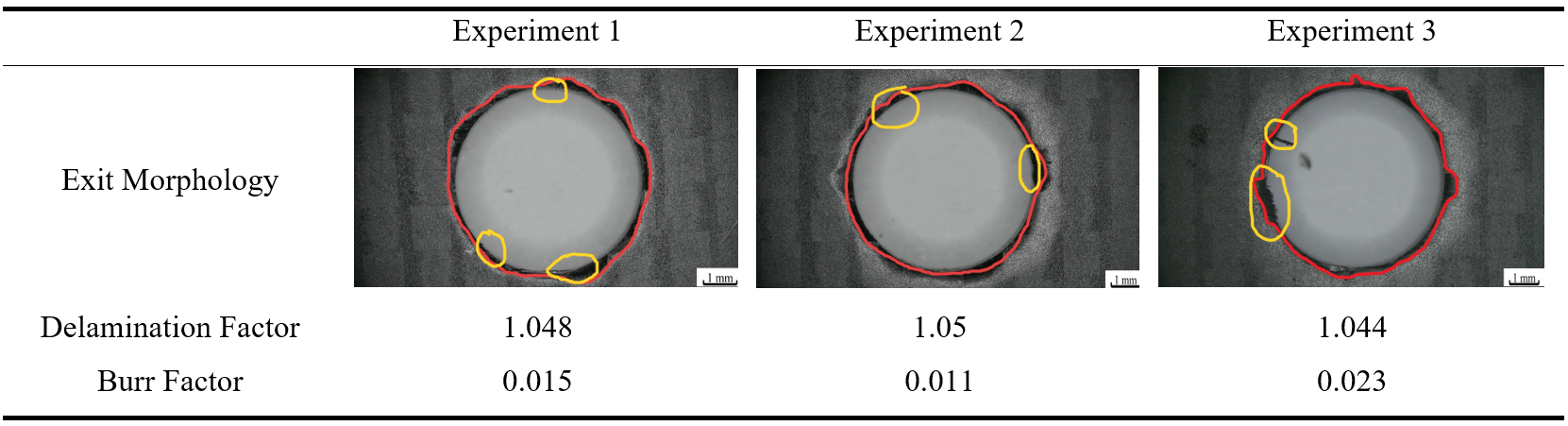
Based on the three sets of experimental data, the exit delamination factor and burr factor of the CFRP holes under this set of process parameters were determined to be 1.047 and 0.016, respectively. Compared to the typical machining process parameters, this represents an 11.2 % improvement in delamination defects and a 61.9 % improvement in burr defects. The measured defect values closely align with those predicted by the optimization model. The observed minor discrepancies are attributed to two primary factors. First, the actual process parameters were selected based on the operational capabilities of the machining center, resulting in slight deviations from the optimal parameters identified by the model. Second, during defect measurement, the faint characteristics of some defects introduced minor inaccuracies. Nevertheless, the optimal solution derived from the optimization model is largely consistent with the experimental results. Therefore, to achieve optimal CFRP hole quality, it is recommended to employ a high spindle speed, low feed rate, and a tool with a small grit number.
-
Analysis of drilling-induced defects indicates that minor tearing damage occurs at the hole entrance, while fiber fracture and crack damage are observed on the hole wall. At the exit, fiber delamination and burrs are present, with the severity of damage increasing with higher feed rates and decreasing with higher spindle speeds. The damage at the exit is more severe than that at the entrance and hole wall, representing the primary defect morphology in carbon fiber composite drilling using the RUD process.
-
Experimental results demonstrate that increasing the spindle speed (7000 r min−1), reducing the feed rate (30 mm min−1), and employing a tool with a small grit number (60 grits) significantly reduce exit delamination and burr formation. Response surface analysis reveals that the feed rate and tool grit number exert the most substantial influence on defects, and their interaction intensifies both delamination and burr generation.
-
The optimal parameter combination obtained through multi-objective optimization is n = 7000 r min−1, f = 30 mm min−1, and S = 60 grit. The delamination factor and burr coefficient are reduced to 1.047 and 0.016, respectively, closely aligning with the model predictions. These research results provide actionable process guidance for high-precision drilling of CFRP components in engineering applications.
All the data used in this paper can be obtained from the corresponding author upon request.
LL: writing – original draft, investigation, software, conceptualization. FZ: writing – review and editing, formal analysis, investigation, data curation, funding acquisition, conceptualization. LD: writing – review and editing. FZ: investigation, data curation. ZZ: funding acquisition.
The contact author has declared that none of the authors has any competing interests.
Publisher's note: Copernicus Publications remains neutral with regard to jurisdictional claims made in the text, published maps, institutional affiliations, or any other geographical representation in this paper. The authors bear the ultimate responsibility for providing appropriate place names. Views expressed in the text are those of the authors and do not necessarily reflect the views of the publisher.
This research is supported by the National Natural Science Foundation of China (grant no. 52075232), funded by the Basic Research Program of Jiangsu (grant no. BK20243025) and the Postgraduate Research & Practice Innovation Program of Jiangsu University of Technology (grant no. XSJCX24_75).
This research has been supported by the National Natural Science Foundation of China (grant no. 52075232), funded by the Basic Research Program of Jiangsu (grant no. BK20243025).
This paper was edited by Jia Ge and reviewed by Tarakeswar Barik and one anonymous referee.
Barile, C., Casavola, C., Pappalettera, G., and Paramsamy Kannan, V.: Laplacian score and K-means data clustering for damage characterization of adhesively bonded CFRP composites by means of acoustic emission technique, Applied Acoustics, 185, 108425, https://doi.org/10.1016/j.apacoust.2021.108425, 2022.
Box, G. E. P. and Wilson, K. B.: On the Experimental Attainment of Optimum Conditions, J. R. Stat. Soc. Series B Stat. Methodol., 13, 1–38, https://doi.org/10.1111/j.2517-6161.1951.tb00067.x, 1951.
Cao, S., Li, H. N., Huang, W., Zhou, Q., Lei, T., and Wu, C.: A delamination prediction model in ultrasonic vibration assisted drilling of CFRP composites, J. Mater. Process. Technol., 302, 117480, https://doi.org/10.1016/j.jmatprotec.2021.117480, 2022.
Du, Y., Yang, T., and Liu, C.: Comparative study on machining performance of conventional and ultrasonic-assisted drilling of carbon fiber-reinforced polyetheretherketone composite, Journal of the Brazilian Society of Mechanical Sciences and Engineering, 45, 540, https://doi.org/10.1007/s40430-023-04460-y, 2023.
Durão, L. M. P., Gonçalves, D. J. S., Tavares, J. M. R. S., de Albuquerque, V. H. C., Aguiar Vieira, A., and Torres Marques, A.: Drilling tool geometry evaluation for reinforced composite laminates, Compos. Struct., 92, 1545–1550, https://doi.org/10.1016/j.compstruct.2009.10.035, 2010.
Ge, J., Luo, M., Zhang, D., Catalanotti, G., Falzon, B. G., McClelland, J., Higgins, C., Jin, Y., and Sun, D.: Temperature field evolution and thermal-mechanical interaction induced damage in drilling of thermoplastic CF/PEKK – A comparative study with thermoset CF/epoxy, J. Manuf. Process., 88, 167–183, https://doi.org/10.1016/j.jmapro.2023.01.042, 2023.
Geng, D., Liu, Y., Shao, Z., Zhang, M., Jiang, X., and Zhang, D.: Delamination formation and suppression during rotary ultrasonic elliptical machining of CFRP, Compos. B Eng., 183, 107698, https://doi.org/10.1016/j.compositesb.2019.107698, 2020.
Henerichs, M., Voß, R., Kuster, F., and Wegener, K.: Machining of carbon fiber reinforced plastics: Influence of tool geometry and fiber orientation on the machining forces, CIRP J. Manuf. Sci. Technol., 9, 136–145, https://doi.org/10.1016/j.cirpj.2014.11.002, 2015.
Jian, W., Ou, X., Sun, L., Chen, Y., Liu, S., Lu, W., Yang, X., Zhao, Z., and Li, Z.: Characterization of anthocyanin accumulation, nutritional properties, and postharvest attributes of transgenic purple tomato, Food Chem., 408, 135181, https://doi.org/10.1016/j.foodchem.2022.135181, 2023.
Jones, B. and Nachtsheim, C. J.: Effective Design-Based Model Selection for Definitive Screening Designs, Technometrics, 59, 319–329, https://doi.org/10.1080/00401706.2016.1234979, 2017.
Lazar, M.-B. and Xirouchakis, P.: Experimental analysis of drilling fiber reinforced composites, Int. J. Mach. Tools Manuf., 51, 937–946, https://doi.org/10.1016/j.ijmachtools.2011.08.009, 2011.
Liu, F., Chen, T., Duan, Z., Suo, Y., and Zhang, C.: Ultrasonic assisted pecking drilling process for CFRP/Ti laminated materials, J. Manuf. Process., 108, 834–851, https://doi.org/10.1016/j.jmapro.2023.11.042, 2023.
Lotfi, M., Charkhian, A., and Akbari, J.: Surface analysis in rotary ultrasonic-assisted milling of CFRP and titanium, J. Manuf. Process., 84, 174–182, https://doi.org/10.1016/j.jmapro.2022.10.006, 2022.
Luo, B., Zhang, K., Liu, S., Cheng, H., and Wang, R.: Investigation on the interface damage in drilling low-stiffness CFRP/Ti stacks, Chinese Journal of Aeronautics, 32, 2211–2221, https://doi.org/10.1016/j.cja.2019.04.017, 2019.
Lv, D., Chen, M., Yao, Y., Yan, C., Chen, G., and Zhu, Y.: High-frequency vibration effects on the hole integrity in rotary ultrasonic drilling of carbon fiber-reinforced plastic composites, Ultrasonics, 115, 106448, https://doi.org/10.1016/j.ultras.2021.106448, 2021.
Mudhukrishnan, M., Hariharan, P., and Palanikumar, K.: Delamination Analysis in Drilling of Carbon Fiber Reinforced Polypropylene (CFR-PP) Composite Materials, Mater. Today Proc., 16, 792–799, https://doi.org/10.1016/j.matpr.2019.05.160, 2019.
Papa, I., Langella, A., and Lopresto, V.: CFRP laminates under low-velocity impact conditions: Influence of matrix and temperature, Polym. Eng. Sci., 59, 2429–2437, https://doi.org/10.1002/pen.25102, 2019.
Priarone, P. C., Robiglio, M., Melentiev, R., and Settineri, L.: Diamond Drilling of Carbon Fiber Reinforced Polymers: Influence of Tool Grit Size and Process Parameters on Workpiece Delamination, Procedia CIRP, 66, 181–186, https://doi.org/10.1016/j.procir.2017.03.296, 2017.
Sanda, A., Arriola, I., Garcia Navas, V., Bengoetxea, I., and Gonzalo, O.: Ultrasonically assisted drilling of carbon fibre reinforced plastics and Ti6Al4V, J. Manuf. Process., 22, 169–176, https://doi.org/10.1016/j.jmapro.2016.03.003, 2016.
Shard, A., Agarwal, R., Gupta, V., and Garg, M. P.: Influence of ultrasonic vibrations during drilling of carbon-fiber-reinforced polyetherimide composites, Applied Acoustics, 202, 109163, https://doi.org/10.1016/j.apacoust.2022.109163, 2023.
Slimane, A., Slimane, S., Kebdani, S., Chaib, M., Dahmane, S., Bouchouicha, B., Sardi, N., and Adjim, S.: Parameters effects analysis of rotary ultrasonic machining on carbon fiber reinforced plastic (CFRP) composite using an interactive RSM Method, International Journal on Interactive Design and Manufacturing (IJIDeM), 13, 521–529, https://doi.org/10.1007/s12008-018-0518-0, 2019.
Spahiu, T., Kitsakis, K., and Kechagias, J. D.: Box-Behnken design to optimise 3D printing parameters in applications for fashion products, International Journal of Experimental Design and Process Optimisation, 7, 49–61, https://doi.org/10.1504/IJEDPO.2022.131225, 2022.
Wang, C., Li, P., Li, S., Qiu, X., Niu, Q., Li, C., and Ko, T. J.: Study on the mechanism and performance of longitudinal-torsional ultrasonic vibration assisted drilling CFRP/Ti stack, J. Manuf. Process., 92, 453–465, https://doi.org/10.1016/j.jmapro.2023.03.005, 2023.
Xia, R. S. and Mahdavian, S. M.: Experimental studies of step drills and establishment of empirical equations for the drilling process, Int. J. Mach. Tools Manuf., 45, 235–240, https://doi.org/10.1016/j.ijmachtools.2004.07.002, 2005.
Xu, C., Yao, S., Wang, G., Wang, Y., and Xu, J.: A prediction model of drilling force in CFRP internal chip removal hole drilling based on support vector regression, The International Journal of Advanced Manufacturing Technology, 117, 1505–1516, https://doi.org/10.1007/s00170-021-07766-0, 2021.
Xu, J., Li, C., Chen, M., El Mansori, M., and Paulo Davim, J.: On the analysis of temperatures, surface morphologies and tool wear in drilling CFRP/Ti6Al4V stacks under different cutting sequence strategies, Compos. Struct., 234, 111708, https://doi.org/10.1016/j.compstruct.2019.111708, 2020.
Xu, J., Yin, Y., Paulo Davim, J., Li, L., Ji, M., Geier, N., and Chen, M.: A critical review addressing drilling-induced damage of CFRP composites, Compos. Struct., 294, 115594, https://doi.org/10.1016/j.compstruct.2022.115594, 2022.
Xu, J., Geier, N., Shen, J., Krishnaraj, V., and Samsudeensadham, S.: A review on CFRP drilling: fundamental mechanisms, damage issues, and approaches toward high-quality drilling, Journal of Materials Research and Technology, 24, 9677–9707, https://doi.org/10.1016/j.jmrt.2023.05.023, 2023.
Zadafiya, K., Bandhu, D., Kumari, S., Chatterjee, S., and Abhishek, K.: Recent trends in drilling of carbon fiber reinforced polymers (CFRPs): A state-of-the-art review, J. Manuf. Process., 69, 47–68, https://doi.org/10.1016/j.jmapro.2021.07.029, 2021.
Zhang, D., Wang, H., Burks, A. R., and Cong, W.: Delamination in rotary ultrasonic machining of CFRP composites: finite element analysis and experimental implementation, The International Journal of Advanced Manufacturing Technology, 107, 3847–3858, https://doi.org/10.1007/s00170-020-05310-0, 2020.
Zhang, S., Wang, W., Jiang, R., Xiong, Y., Huang, B., and Wang, J.: Multi-objective optimization for the machining performance during ultrasonic vibration-assisted helical grinding hole of thin-walled CF/BMI composite laminates, Thin-Walled Structures, 192, 111086, https://doi.org/10.1016/j.tws.2023.111086, 2023.
Zhang, Z., Jiao, F., Li, Y., Wang, X., Niu, Y., and Tong, J.: Experimental study on rotary longitudinal-torsional ultrasonic machining of unidirectional CFRP, Chinese Journal of Aeronautics, 37, 517–534, https://doi.org/10.1016/j.cja.2024.02.012, 2024.
Zhu, F., Zhang, H., Hu, K., Duan, L., Zhang, K., and Xu, X.: A comparative investigation on surface quality of CFRP laminates between rotary drilling and rotary ultrasonic-assisted drilling, Compos. Struct., 358, 118964, https://doi.org/10.1016/j.compstruct.2025.118964, 2025.
Zhu, W., Fu, H., Li, F., Ji, X., Li, Y., and Bai, F.: Optimization of CFRP drilling process: a review, The International Journal of Advanced Manufacturing Technology, 123, 1403–1432, https://doi.org/10.1007/s00170-022-10112-7, 2022.