the Creative Commons Attribution 4.0 License.
the Creative Commons Attribution 4.0 License.
 | 23 Jan 2026
Design and experimental verification of the loading mechanism for a compact bolt installation tool
Li Wensheng
Wu Kun
Wang Shuai
Xia Binhong
Zuo Dunwen
Lu Wenzhuang
In this study, a bolt installation tool loading mechanism has been developed to overcome the constraints posed by compact space in the assembly of aero-engines and airframes. The loading mechanism features a thin-walled structure, allowing it to adapt to compact working space, and achieves high torque output through the coordinated drive of the ratchet–pawl mechanism and the hydraulic cylinder. A detailed design was carried out for the thin-walled structure, force arm dimensions, and ratchet tooth profile in the loading mechanism. Through dynamic simulation analysis, the strength safety of key components under a torque of 120 N m and the rationality of symmetrical design were verified. Experimental results demonstrated that the tool can deliver an average torque of 136.3 N m within a space as narrow as 4 mm, fulfilling the design requirements. The findings of this paper provide a reliable solution for the assembly of high-strength bolts in the compact space of a lean engine, significantly enhancing assembly efficiency and safety.
- Article
(6346 KB) - Full-text XML
- BibTeX
- EndNote


Threaded connections are widely used and are essential for connecting components in aircraft and their engines (Li et al., 2023). Proper installation and removal of bolts are critical steps in the assembly process as the reliability of these connections directly impacts the safety of both the aircraft and its engines (Liu et al., 2022a). During the assembly and maintenance of aircraft engines and airframes, compact designs often lead to significant space constraints when installing or removing certain bolts (Wang and Chen, 2020). Additionally, fasteners are typically manufactured from superalloy materials (Boyer et al., 2015), which require a tensile strength grade of over 900 MPa (Chen et al., 2023). Therefore, a high-precision assembly torque must be applied (Rousseau and Bouzid, 2024). In practical assembly operations, the operator often relies on an open-end manual wrench to perform small-angle reciprocating loading. This approach leads to decreased assembly reliability, lower operational efficiency, and increased labor intensity.
Electric wrenches and electric impact wrenches provide precise control over torque (Wang et al., 2024; He and Wu, 2018), making them suitable for assembly operations that require high accuracy. However, when high torque is necessary, these tools often depend on powerful motors, which can increase their size and make them unsuitable for use in compact spaces. Hydraulic wrenches deliver very high torque output using hydraulic systems. They are commonly employed in applications that require significant torque and offer a stable and robust torque output (Yang et al., 2016). However, they are unsuitable for compact spaces.
Jiang et al. (2023) proposed a new type of humanoid robot featuring a compact S-shaped arm structure. This arm consists of one prismatic joint and four rotary joints, enabling flexible positioning and operation of bolts in tight spaces. However, the design primarily addresses scenarios with compact axial space and does not resolve issues related to radial space constraints.
Ma et al. (2015) proposed a new wrench design that incorporates a flexible hinge. This wrench features an opening in the hinge, allowing it to transmit torque while tightening. During the return stroke, it can detach from the workpiece, enabling a continuous assembly operation even in compact spaces. However, since the spanner is made of flexible materials, it is not suitable for applications that require handling high torque. Zeng (2020) proposed a special wrench design optimized for small spaces. This design utilizes a combination of flexible cable transmission and gear thread coupling to enable continuous movement of the sleeve in compact areas. However, the low strength of the flexible cable makes it unsuitable for applications that require high torque.
The transmission mechanism plays a crucial role in installation tools, with common modes including ratchet–pawl transmission, gear transmission, and worm gear transmission. Gear drives are known for their compact structure and high transmission efficiency (Croccolo et al., 2020). In contrast, worm gear drives can provide a high transmission ratio but typically have lower efficiency (Honkalas et al., 2021). Unlike these two types, ratchet–pawl transmission is a one-way, intermittent motion mechanism that cannot achieve continuous transmission; however, it features a simple structure and low manufacturing costs (Zhou et al., 2012; Li et al., 2024). It is important to note that contact patterns differ between these systems. Gear and worm gear drives primarily exhibit wire contact or near-wire contact (Ni et al., 2024; Liu et al., 2022b), while ratchet–pawl mechanisms generally show face contact during the meshing process. As a result, under the same load conditions, the contact stress distribution in the ratchet–pawl transmission system is more favorable (Zhang and Ren, 2021). This characteristic helps reduce the geometric size and overall volume of key stressed components.
In this paper, we propose a new type of loading mechanism designed to address existing challenges. This mechanism combines a ratchet–pawl drive with a hydraulic cylinder, allowing for continuous one-way loading through the hydraulic cylinder's reciprocating motion. This paper focuses on two main areas: the design of a thin-walled structure suitable for compact spaces and the optimization of ratchet–pawl tooth shapes to enhance overall strength. By conducting finite-element simulation analysis and experimental verification, we demonstrate that this loading mechanism can effectively install large torque bolts within confined spaces. This paper offers a reliable and efficient solution for the assembly of high-strength bolts in compact environments and paves the way for the development of intelligent and compact assembly tools for advanced engineering applications.
This study was conducted with M12 bolts under the following conditions: the opposite-side size of the bolt head was 18 mm, the radial distance between the edge of the bolt head and the constrained point was a minimum of 4 mm, and the tightening torque was 120 N m.
2.1 Introduction to the loading mechanism structure
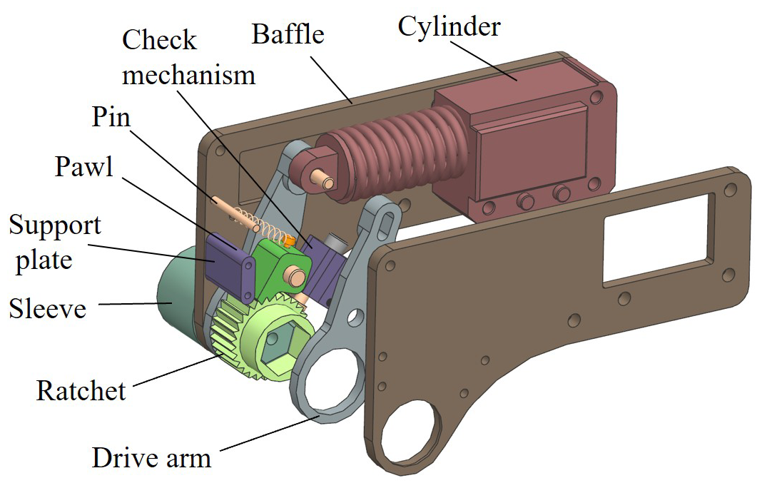
Figure 1 illustrates the structural composition of the loading mechanism, which primarily consists of the sleeve, ratchet, pawl, drive arms, baffles, hydraulic cylinder, and check mechanism. The lower end of the sleeve is engaged with the bolt, while the upper end connects to the ratchet, which, in turn, is engaged with the pawl. The drive arm is positioned on both sides of the ratchet. When the drive arm swings, the pawl rotates, thereby driving the ratchet to rotate as well. Baffles are positioned on either side of the drive arms; the tail end of each baffle connects to the hydraulic cylinder, which pushes the drive arm to swing. On the right side of the ratchet, there is a check mechanism designed to prevent the ratchet from reversing during the return stroke. The base of the check mechanism and the left supporting plate work together to support the baffle and maintain its parallelism. Above the left supporting plate, a pin is connected to a tension spring, while the other end of the tension spring is fixed to a screw located at the upper end of the pawl. This setup ensures that the pawl remains tightly engaged with the ratchet under tension. The loading mechanism uses a unidirectional hydraulic cylinder as its power source, which operates in two stages: propulsion and return. The specific workflow is outlined as follows:
- 1.
Propulsion stage. When the hydraulic system supplies oil, the piston rod of the cylinder extends outward due to hydraulic pressure, simultaneously stretching the spring. The piston rod is rigidly connected to the drive arm via a pin, causing the drive arm to swing forward. As the pawl is fixed to the drive arm through the pin and engages with the ratchet, the swinging motion of the drive arm rotates the ratchet counterclockwise. This drives the sleeve to rotate synchronously, enabling the tightening of bolts or screws.
- 2.
Return stage. After the hydraulic cylinder is depressurized, the reset spring contracts, pulling the piston rod back while the driving arm swings in the opposite direction. At this point, the pawl slides along the tooth surface of the ratchet. The check shaft locks the ratchet due to spring pressure, preventing any reverse movement. Once the piston rod is fully retracted, the pawl re-engages with the ratchet, readying the mechanism for the next working cycle.
2.2 Key structure design
2.2.1 Thin-wall structure design
Based on the introduction of the first section, we show the compact space in Fig. 2b. In this figure, Dmax represents the maximum size available in the radial space, Lmin denotes the minimum distance between the bolt head and the constrained point, and S indicates the thickness of the bolt head. Additionally, the maximum size of the radial space, Dmax, must conform to the following formula:
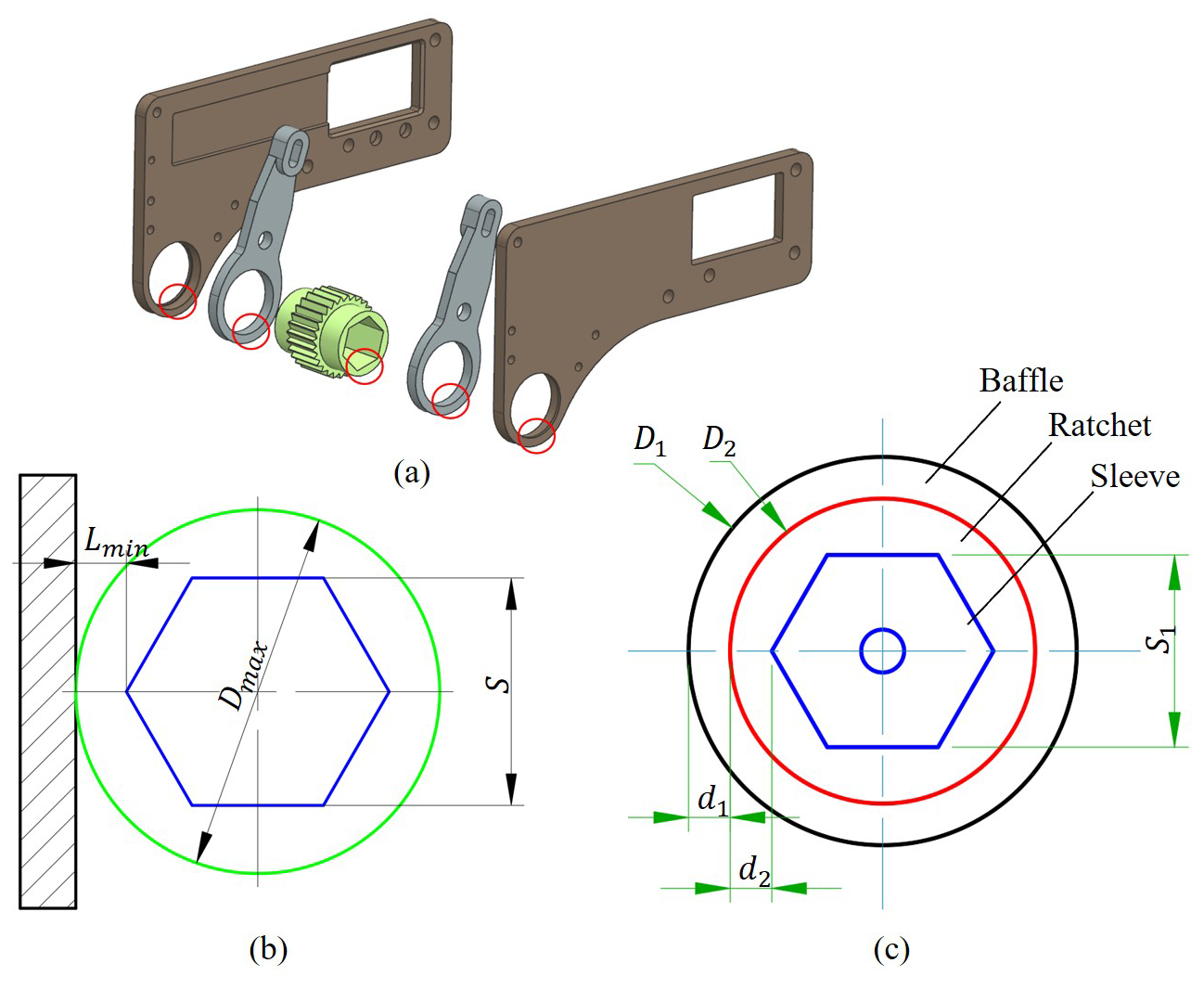
Figure 2Design model diagrams of thin-walled structure: (a) thin-walled structure model diagram of each part of the loading mechanism; (b) calculation model diagram of radial maximum available size in compact space; (c) wall thickness calculation model diagram of thin-walled structure.
In this compact space, there are three components: the baffle, the ratchet, and the sleeve. As illustrated in Fig. 2c, D1 represents the outer diameter of the round hole in the baffle, D2 indicates the diameter at both ends of the ratchet, S1 is the distance measured between the opposite sides of the upper end of the sleeve, d1 denotes the thickness of the round hole in the baffle, and d2 refers to the thickness at both ends of the ratchet. The following relationships exist among these parameters:
The distance Lmin between the bolt head and the constrained point is very small, which results in the maximum radial diameter Dmax being very small. The outer diameter of the round hole in the baffles must be less than the maximum radial diameter available, meaning that D1<Dmax. Accordingly, the thickness of the round hole d1 in the baffles, the thickness d2 at both ends of the ratchet, and the thickness of the round hole in the drive arm are all minimal. As a result, these components appear as thin-walled structures, as illustrated in Fig. 2a.
2.2.2 Drive arm design
The length of the drive arm is related to the stroke of the hydraulic cylinder, the rotation angle of the drive arm, etc. Therefore, a model is established, as shown in Fig. 3, which includes the stroke of the hydraulic cylinder l, the effective angle of one stroke rotation of the driving arm θ, the idle angle θ1, the idle angle of the push stroke θ2, the idle angle of the return stroke θ3, the movable length of the pin shaft h2, and the length of the drive arm L. They have the following relationship:
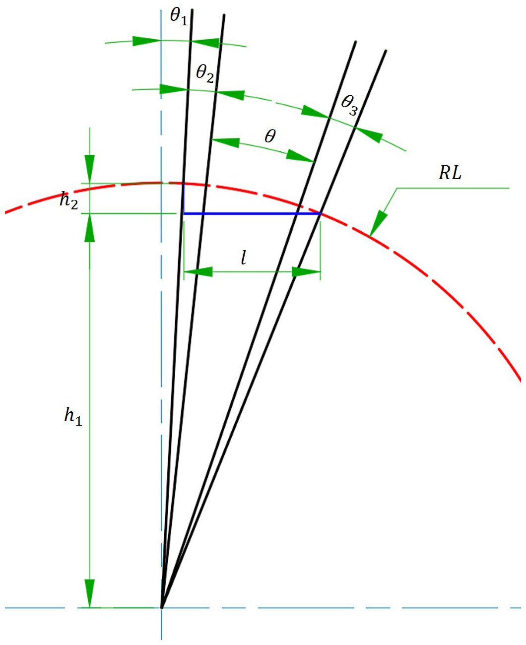
We set the effective angle of the drive arm as , where z is the number of teeth of the ratchet. This setting helps prevent misalignment between the ratchet and the pawl during operation. Additionally, setting the idle angle can effectively resolve issues related to improper meshing between the ratchet and pawl that may arise from manufacturing tolerances.
2.2.3 Ratchet design
According to the previous analysis, given the constraint of the maximum available radial size, if the ratchet diameter (D) is designed to be 28 mm and the intended modulus (m) is 1 mm, the number of ratchet teeth (z) can be calculated to be 28. According to the theoretical analysis, increasing the number of meshing teeth can reduce the load on individual teeth. However, the combined effect of multiple ratchet teeth may increase the idle stroke needed for the ratchet–pawl to transition from the non-meshing state to the meshing state. If the idle stroke is excessive, it can lower the transmission efficiency of the mechanism and increase the impact on the ratchet. After a comprehensive evaluation, the double-tooth meshing scheme has been chosen for this design.
The tooth deviation angle (θd) and the tooth profile angle (θs) are crucial parameters that influence load distribution. If the tooth deviation angle is either too large or too small, it can negatively impact the load distribution between the two teeth. As illustrated in Fig. 4a, when the tooth deviation angle is denoted as θ5, the vertical line of the tooth surface moves away from the center of rotation of the pawl. This misalignment decreases the force on the first tooth while concentrating the load on the second tooth, leading to a significant imbalance in force distribution. To quantitatively analyze this phenomenon, a parametric model was developed using the static-structure module (Wang et al., 2021). This model allows for the observation of stress distribution characteristics in double teeth under varying tooth angles.
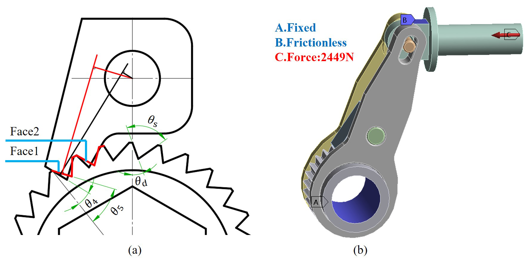
Figure 4Analysis diagrams of ratchet teeth deflection angle: (a) engagement model diagram of ratchet–pawl with different teeth deflection angles; (b) finite-element simulation model diagram of ratchet gear deflection analysis.
One can simplify the model by retaining only the moving parts, as shown in Fig. 4b. Begin by using the “surface mesh subdivision” command to regularize the mesh of the contact surface between the ratchet and the pawl. Next, apply the “surface size adjustment” command to refine the mesh to ensure calculation accuracy. For all contact surfaces, utilize frictional contact with a friction coefficient of 0.1. The contact algorithm should employ a Lagrangian method to improve convergence (Hassan et al., 2019). Constrain all degrees of freedom on the ratchet's internal surface, simulating bolt fixation. Additionally, there should be a frictionless support constraint on the plane of the piston rod to allow it to keep moving at the same height. Finally, apply a concentrated force to the tail end of the piston rod, determining its value through calculations based on the torque balance equation.
where T is the tightening torque, and Ft is the force.
Set the tooth inclination angles to 35, 30, 25, 20, and 15°. Next, calculate the average stress, the difference in average stress, and the maximum stress on the ratchet, as shown in Table 1. The stress difference quantitatively characterizes the degree of uneven load distribution. The stress values are displayed in a bar chart in Fig. 5. The stress cloud map for the two contact surfaces at different tooth angles is shown in Fig. 6. From Fig. 5, it can be observed that, as the tooth deviation angle decreases, the maximum stress on the ratchet initially decreases and then increases. Additionally, the difference in average stress between the two contact surfaces also shows a similar trend, decreasing before it begins to rise again. Notably, when the tooth deviation angle is 20°, the difference in average stress between the two contact surfaces approaches zero. Figure 6 further illustrates that the stress distribution on both contact surfaces is nearly identical when the tooth deviation angle is 20°. Therefore, it can be concluded that the load distribution between the two teeth reaches an equilibrium state at this angle. Ultimately, the optimal tooth deviation angle is determined to be 20°.
Table 1Table of stress magnitude of the ratchet under different tooth angles.
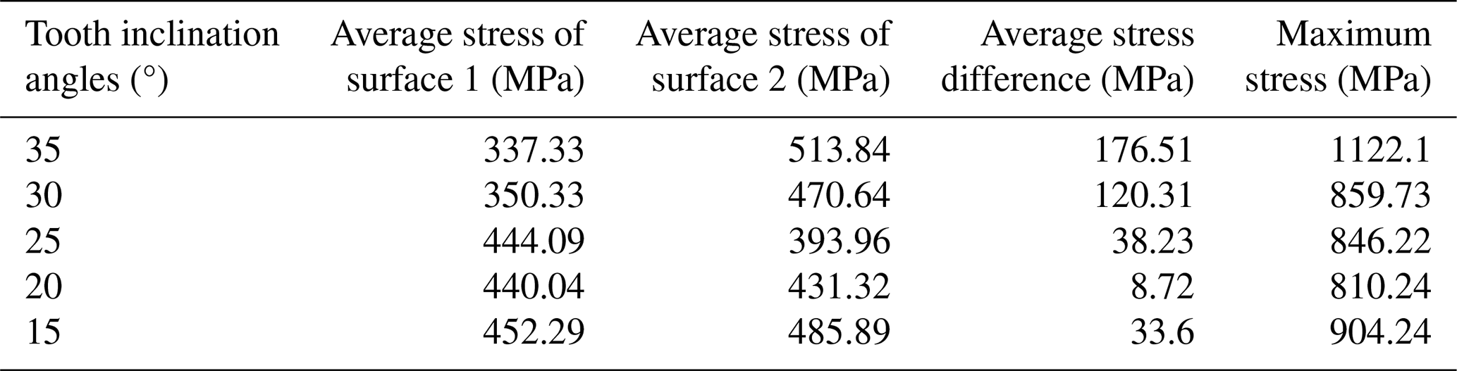
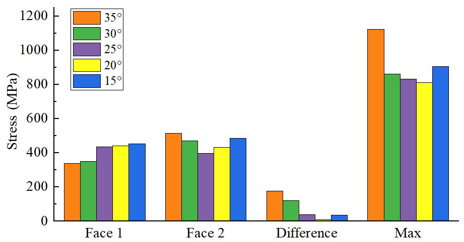
Figure 5Stress histogram of different contact surfaces under different tooth angles of the ratchet.
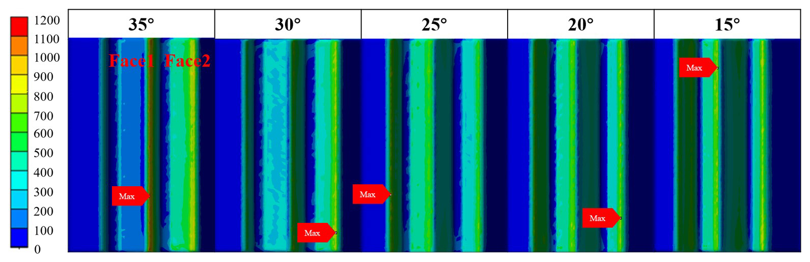
Figure 6Stress cloud maps of different contact surfaces under different tooth angles of the ratchet.
2.3 Working-process analysis of the loading mechanism
- 1.
When the piston rod is in its initial position with a displacement of 0, the ratchet and pawl are not engaged, while the check shaft and ratchet are in a meshing state, as illustrated in Fig. 7a.
- 2.
As the piston rod moves forward, the ratchet remains stationary until the ratchet and pawl engage, which occurs at a displacement of 2.4 mm, as shown in Fig. 7b.
- 3.
Continuing forward, the piston rod pushes the ratchet, causing it to rotate counterclockwise. When the piston rod reaches a displacement of 14 mm, the ratchet rotates by an angle of 13°, and the check shaft engages with the next tooth of the ratchet, as depicted in Fig. 7d.
- 4.
Figure 7c illustrates the position of the piston rod at displacements of 2.4 and 14 mm, with the ratchet rotating counterclockwise and the check shaft retracting.
- 5.
The piston rod continues to move forward, and the ratchet rotates counterclockwise by 3°. At this time, the displacement of the piston rod is 17 mm, and the process ends. At this time, the ratchet and pawl are in the meshing state, and the check shaft and ratchet are in no meshing state, as shown in Fig. 7e. The 3 mm stroke serves as a safeguard to ensure that the check shaft can re-engage with the ratchet, accounting for any variability due to manufacturing quality.
- 6.
After completing this process, the piston rod begins its reverse movement. Due to the friction between the drive arm and the ratchet, as well as the friction between the pawl and the ratchet, the ratchet will move in reverse until its teeth align with the position of the check shaft. At this point, the piston rod's displacement is 14 mm, as shown in Fig. 7f, which is consistent with the position in Fig. 7d.
- 7.
The check shaft impedes the ratchet's rotation as the piston rod moves backward. The ratchet and pawl disengage until the piston rod returns to its initial position, where displacement is 0, as shown in Fig. 7h.
- 8.
Figure 7g represents an intermediate state, where the pawl teeth glide over the ratchet teeth until the piston rod's displacement reaches 0.
During this process, the pawl teeth skip over one tooth of the ratchet. This completes a single reciprocating motion, allowing the piston rod to continue its motion for ongoing tightening of the bolt or screw.
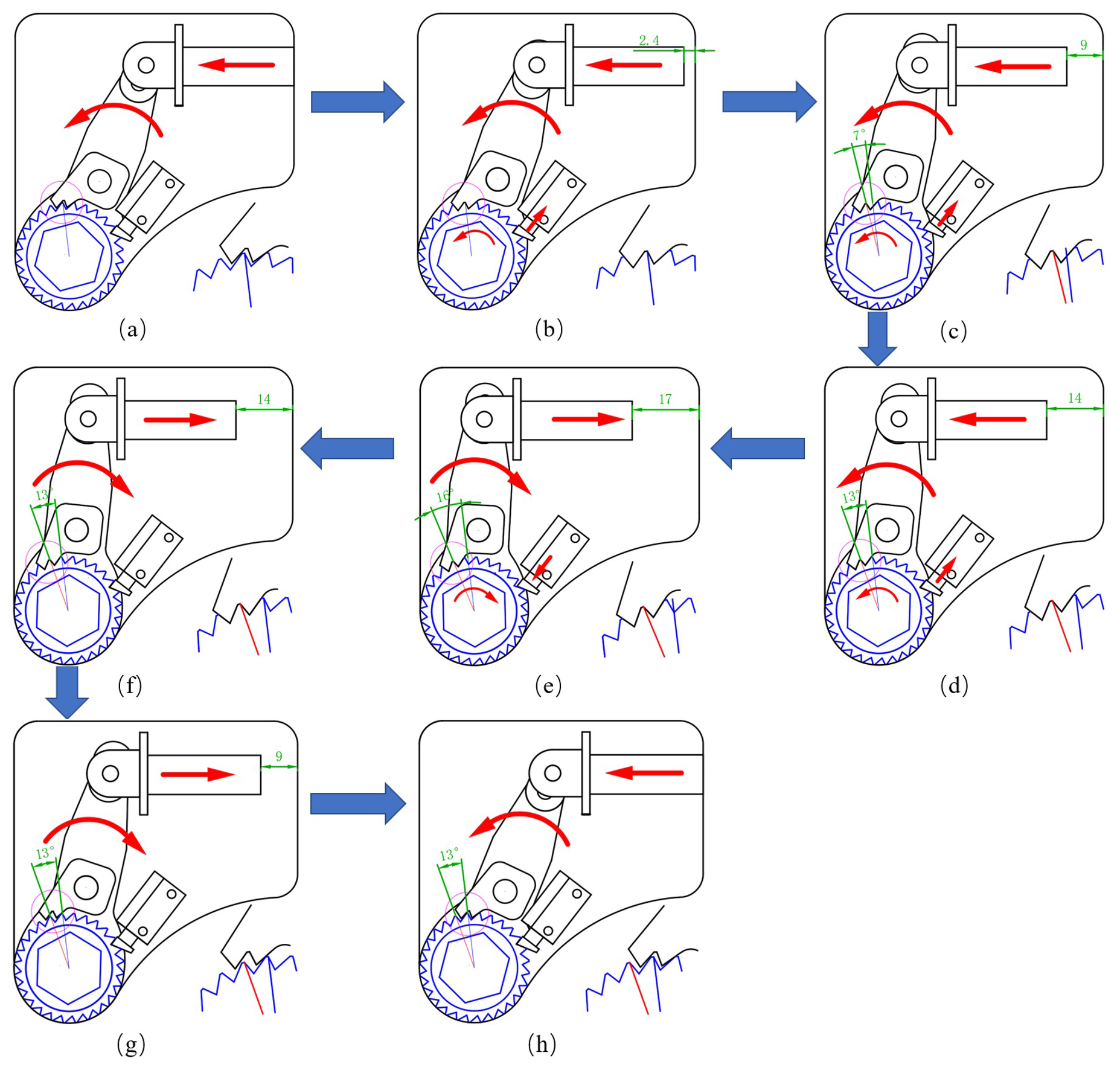
Figure 7Position diagrams of each component during the working process of the loading mechanism.
The transient structural module of finite-element simulation provides high-precision dynamic simulation capabilities that surpass those of the rigid-body dynamics and static-structure modules (Lu et al., 2021). This module can simulate time-varying motion, similarly to rigid-body dynamics, while also calculating elastic–plastic deformation and the stress–strain distribution. Additionally, it addresses the challenges posed by inertia effects, damping, and time-varying loads that are not considered in static analysis. As a result, it accurately captures the dynamic response of the structure during transient processes. Therefore, using this module to calculate the stress and deformation distribution of the loading mechanism, the fundamental equation of transient structural dynamics is as follows:
where M is the mass matrix, C is the damping matrix, K is the spring stiffness, and F(t) is the external time-varying load vector.
3.1 Material selection
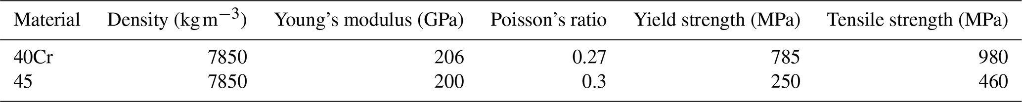
Due to the high tightening torque, the main transmission components must possess significant strength and hardness. Therefore, the ratchet, pawl, and drive arm are made from quenched and tempered 40Cr steel (Li et al., 2013), achieving a hardness of 32–36 HRC after treatment. The remaining parts are composed of 45 steel (Tyutina et al., 2018), and the material parameters are detailed in Table 2.
3.2 Model establishment
Since the tool operates with an external hydraulic pump, it generates a reaction torque that works in the opposite direction during tightening or loosening. To effectively counter this torque, a reaction block is located at the bottom of the tool's tail end, providing the necessary reaction force. The cylinder model is divided into two components, namely the piston rod and the cylinder block, allowing for easier addition of subsequent loads.
To simplify the calculation, only the stress and deformation during the propulsion process are analyzed, while the stress and deformation in the return stage are not considered; only the check base in the check mechanism is retained. To enhance calculation efficiency, certain components that have minimal impact on stress and deformation calculations are treated as rigid bodies. These components include the sleeve, check base, lower support plates, upper support copper column, and stop block, which are excluded from the stress and deformation analyses.
3.3 Boundary condition settings
To effectively replicate real working conditions, it is essential to correctly establish the motion pairs, the position of contact, the type of contact, and the loads involved. Rotary-motion pairs are incorporated between parts that experience relative rotation, including those between the ratchet and the drive arm, the ratchet and the baffle, and the pin and the pawl.
Considering the cylinder piston rod as a linear moving part, a translational-motion pair will be created between the piston rod and the ground to replicate the movement of the piston rod. Additionally, the pin at the top of the drive arm travels within the slot, and a translational-motion pair will be added between the pin and the drive arm.
Since the reaction block is a fixed component, a fixed-motion pair is established between the reaction block and the ground, and a translational-motion pair is created between the reaction block and the tool. The ratchet and pawl will engage, and the contact surface will be designated as a friction contact with a friction coefficient of 0.1.
To simulate the tightening torque, a torque will be applied to the outer circular surface of the sleeve, and a reaction force will be introduced at the front end of the cylinder block, as illustrated in Fig. 8.
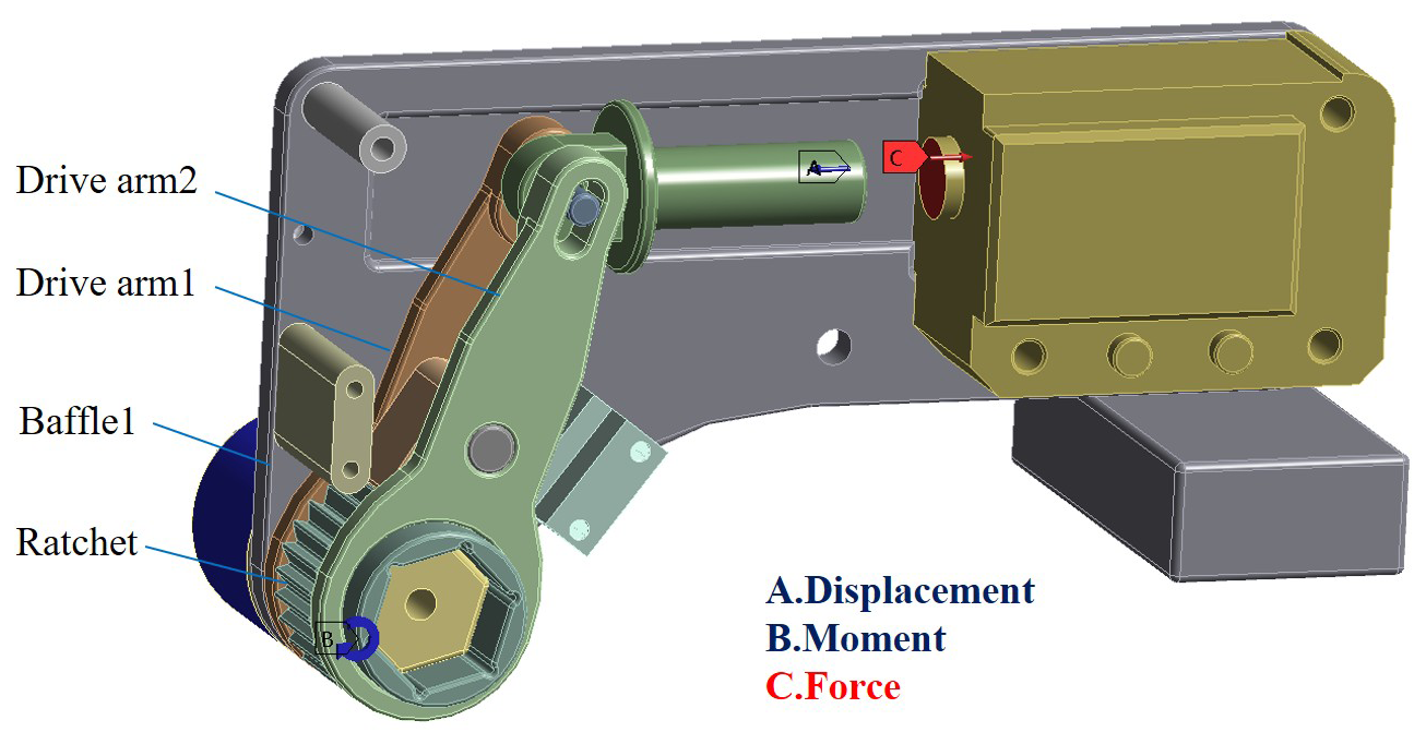
Figure 8Simulation model diagram for the dynamics of the loading mechanism and the establishment of boundary conditions.
To ensure accurate results, the load is applied under two working conditions.
- 1.
Condition 1. Research on the mechanical characteristics of bolted connections shows that, during the elastic deformation stage, there is an approximately linear relationship between the bolt tightening torque and the rotation angle (Chen et al., 2022). This relationship can be represented by a simplified mathematical model, which can be expressed as follows:
where C is a constant, and θ is the tightening angle. In this analysis, we focus on the last propulsion phase. Figure 9a illustrates the changes in tightening torque. Displacement is added to the moving pair of the piston rod, and the displacement curve is depicted in Fig. 9b. A force is applied to the front of the cylinder block to serve as the reaction force. This force must be equal to the thrust of the piston rod but directed opposite to the thrust direction. After calculating the thrust of the piston rod using Eq. (6), the reaction force curve shown in Fig. 9c can be obtained.
- 2.
Condition 2. To ensure that the strength of the parts in the loading mechanism meets the requirements during the propulsion phase, the tightening torque and the reaction force remain constant throughout the process, as shown in Fig. 9.
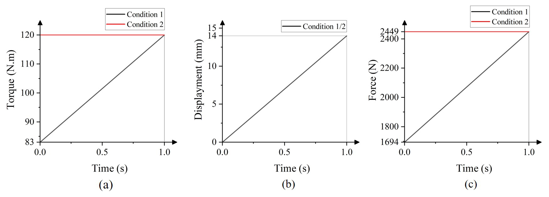
Figure 9Curve diagrams of boundary conditions applied under various working conditions: (a) torque of the sleeve versus time; (b) displacement of the piston rod over time; (c) thrust of the piston rod over time.
3.4 Solution and result analysis
Set the solving time to 1 s, the number of solving steps to 1, the minimum sub-step to 20, the maximum sub-step to 250, and the initial sub-step to 25. Open the weak spring and enable large deflection.
In this loading mechanism, the ratchet, pawl, and two drive arms are transmission parts, and both ends of the ratchet, the circular holes of the drive arm, and the circular holes of the two baffles are thin-walled structures (Bin et al., 2022). Whether they meet the strength requirements is very important to the design of the tool.
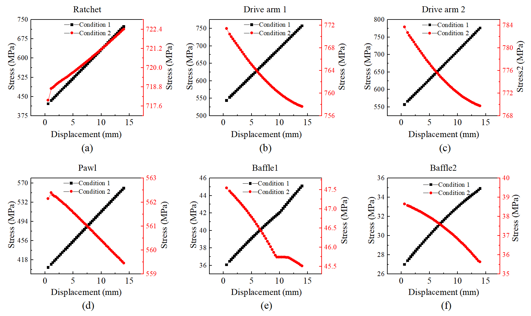
Figure 10The curves of maximum equivalent stress for each component vary with displacement under different working conditions: (a) ratchet, (b) drive arm 1, (c) drive arm 2, (d) pawl, (e) baffle 1, (f) baffle 2.
From the curve of maximum equivalent stress for each component as a function of displacement presented in Fig. 10, the conclusion outlined below can be drawn.
Under the boundary conditions of condition (1), the maximum equivalent stress of each transmission component shows a roughly linear positive correlation with displacement. Under condition (2), only the maximum equivalent stress of the ratchet increases with displacement, while the stress in the other components tends to decrease.
By comparing the maximum stress values of each part under the two working conditions with Table 3, it is evident that the maximum equivalent stress of all key components remains below the yield strength of the material (Vukelic et al., 2019). This indicates that the strength design adheres to safety requirements. The stress nephogram for each component is presented in Fig. 11. The maximum stress on the ratchet occurs at the root of the tooth, indicating that the thin-walled structures at both ends satisfy the strength requirements. Similarly, the maximum stress on the two drive arms is found in the arc, which suggests that the thin-walled structure around the circular hole also meets strength standards. In conclusion, all transmission components and thin-walled structures fulfill the necessary strength requirements.
Table 3Table of equivalent stress under different working conditions.
Figure 11Stress nephograms of different parts: (a) ratchet, (b) drive arm 1, (c) baffle 1, (d) pawl, (e) drive arm 2, (f) baffle 2.
Aside from the sleeve, the mechanism features a symmetrical design, and the balance of forces in symmetrical components can be verified through dynamic force analysis. Figure 12 illustrates the resultant force and displacement curves of the rotary-motion pair between the ratchet and the drive arms, the rotary-motion pair between the ratchet and the baffles, and the translational-motion pair between the upper end of the drive arms and the pin. Based on Fig. 11, it is evident that, under both operating conditions, the stress on the inner circular surface of baffle 1 consistently exceeds that of baffle 2. This is directly related to the fact that the resultant force between the ratchet and baffle 1 is greater than that between the ratchet and baffle 2, as illustrated in Fig. 12. However, since both stress values remain significantly below the material yield strength, it is reasonable to use the same structure for both the left and right baffles.
Figure 12The curves of the resultant force for each motion pair vary with displacement under different working conditions: (a) the motion pair between the ratchet and baffle 1, (b) the motion pair between the ratchet and arm 1, (c) the motion pair between arm 1 and the pin, (d) the motion pair between the ratchet and baffle 2, (e) the motion pair between the ratchet and arm 2, (f) the motion pair between arm 2 and the pin.
Additionally, based on Figs. 11 and 12, the maximum equivalent stress difference between drive arm 1 and drive arm 2 is less than 5 %, and the deviation of the resultant force between the drive arm and the ratchet and pin can be considered to be negligible. We believe that it is reasonable to use the same structure for the drive arm.
Overall, this analysis demonstrates that the symmetrical design of the mechanism not only simplifies the manufacturing and assembly processes but also ensures mechanical equilibrium.
- 1.
Spatial adaptability testing. The experimental device consists of various components, including a tool, a disk, a limit block, and a reaction block. By adjusting the position of the limit block, we set the distance between the bolt head and the constrained point to 4 mm, as illustrated in Fig. 13a. Place the sleeve and tool in position on the bolt head, ensuring that the tool fits the reaction block, as shown in Fig. 13b. The experimental results indicate that, within the 4 mm space constraint, the tool can be smoothly placed in the desired working position without any interference, confirming the spatial adaptability of the designed loading mechanism.
- 2.
Torque performance test. The experimental device primarily consists of various components, including a tool, a limit block, a reaction block, a high-pressure oil pipe, a hydraulic pump, and a digital torque wrench, as illustrated in Fig. 13c. Set the output pressure of the hydraulic pump to 15 MPa and control the tool to operate continuously through a switch valve. Once the bolt stops rotating, remove the tool and disconnect the power supply of the hydraulic pump. A digital torque wrench will be used to measure the loosening torque, which will serve as an approximate value for the tightening torque.
This experiment involves four repeated trials, and the test data obtained are presented in Table 4 below. According to the experimental data, the tool can achieve an average output torque of 136 N m.
Figure 13Diagrams of the experimental testing device for the loading mechanism: (a) compact space display diagram, (b) diagram of the space adaptability testing device, (c) diagram of the torque output performance testing device.
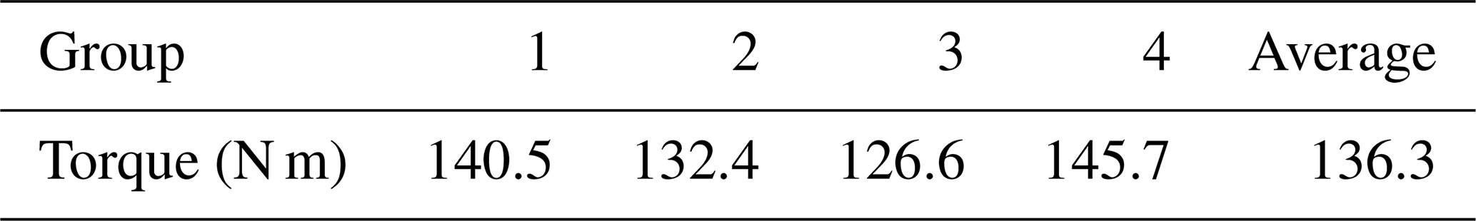
The experimental data indicate that the tool can achieve an output torque of 136 N m under the constraint of a 4 mm compact space, meeting the design requirement of a torque of 120 N m. Additionally, each component meets the strength requirement without any fractures or deformations.
This article presents the design and validation of a bolt installation tool loading mechanism specifically tailored for the confined workspace of aircraft engines. The mechanism employs a ratchet–pawl system for transmission and utilizes a hydraulic cylinder as its driving force. This design effectively combines the high load-bearing capacity of the ratchet–pawl with the powerful output of the hydraulic system, ensuring reliable tightening of high-torque bolts. To accommodate the compact space, a thin-walled structure is implemented at the end of the loading mechanism. Dynamic simulation results indicate that this structure meets the necessary strength requirements. By optimizing the tooth angle of the ratchet and pawl, the force distribution between the two meshing components becomes more balanced, which enhances the overall load-bearing capacity of the mechanism. Experimental results demonstrate that the loading mechanism achieved an average torque output of 136 N m despite having only 4 mm of radial space available. This performance exceeds the design standard of 120 N m, confirming its capability to deliver high torque output even under extreme conditions.
All the data used in this paper can be obtained upon request to the corresponding author.
LW conceptualized the study and reviewed the paper. WK edited the paper. WS and XB supervised the work. ZD and LW directed the writing of the paper.
The contact author has declared that none of the authors has any competing interests.
Publisher's note: Copernicus Publications remains neutral with regard to jurisdictional claims made in the text, published maps, institutional affiliations, or any other geographical representation in this paper. The authors bear the ultimate responsibility for providing appropriate place names. Views expressed in the text are those of the authors and do not necessarily reflect the views of the publisher.
The authors acknowledge Mr. Sun Yebin from Nanjing University of Aeronautics and Astronautics for his valuable suggestions on part design and machining. We also extend our gratitude to the editors and reviewers for their diligent work and constructive comments.
This work was supported by Tianjin Key Laboratory of Fastening Technology (grant no. TKLF2023-01-A-03) and the Aviation Science Foundation of China (grant no. 20220019052001).
This paper was edited by Haitong Liang and reviewed by Siyuan Ye and one anonymous referee.
Bin Kamarudin, M. N., Mohamed Ali, J. S., Aabid, A., and Ibrahim, Y. E.: Buckling Analysis of a Thin-Walled Structure Using Finite Element Method and Design of Experiments, Aerospace, 9, 541, https://doi.org/10.3390/aerospace9100541, 2022.
Boyer, R. R., Cotton, J. D., Mohaghegh, M., and Schafrik, R. E.: Materials Considerations for Aerospace Applications, MRS Bulletin, 40, 1055–1066, https://doi.org/10.1557/mrs.2015.278, 2015.
Chen, C.-M., Chang, H.-L., and Lee, C.-Y.: An Experimental Study on the Torsional Stiffness and Limit Torque of a Jaw Coupling with Consideration of Spacer's Hardness and Installation Methods, J. Mech., 38, 195–203, https://doi.org/10.1093/jom/ufac018, 2022.
Chen, P., Ye, X., Liu, H., Hu, Y., and Yu, X.: Axial Stress Measurement of Bolts Based on Ultrasonic Energy Attenuation, Hangkong Xuebao/Acta Aeronautica et Astronautica Sinica, 44, https://doi.org/10.7527/S1000-6893.2022.27250, 2023.
Croccolo, D., De Agostinis, M., Olmi, G., and Vincenzi, N.: A Practical Approach to Gear Design and Lubrication: A Review, Lubricants, 8, 84, https://doi.org/10.3390/lubricants8090084, 2020.
Hassan, S. N. H. B., Niimi, T., and Yamashita, N.: Augmented Lagrangian Method with Alternating Constraints for Nonlinear Optimization Problems, J. Optim. Theory Appl., 181, 883–904, https://doi.org/10.1007/s10957-019-01488-w, 2019.
He, C. and Wu, T.: Permanent Magnet Brushless DC Motor and Mechanical Structure Design for the Electric Impact Wrench System, Energies, 11, 1360, https://doi.org/10.3390/en11061360, 2018.
Honkalas, R., Deshmukh, B., and Pawar, P.: A Review on Design and Efficiency Improvement of Worm and Worm Wheel of a Gear Motor, J. Phys.: Conf. Ser., 1969, 012023, https://doi.org/10.1088/1742-6596/1969/1/012023, 2021.
Jiang, J., You, J., and Bi, Y.: Kinematic Modeling and Simulation of a New Robot for Wingbox Internal Fastening Application, Machines, 11, 753, https://doi.org/10.3390/machines11070753, 2023.
Li, Y., Pan, X., and Wang, G.: Low Cycle Fatigue and Ratcheting Properties of Steel 40Cr under Stress Controlled Tests, Int. J. Fatigue, 55, 74–80, https://doi.org/10.1016/j.ijfatigue.2013.05.011, 2013.
Li, Y., Liu, W., Wu, J., Zhang, Z., Wu, X., Zeng, L., Hao, D., Zhao, J., and Zhou, X.: A Self-Powered Smart Wave Energy Harvester with Ratchet and Pawl for Sea-Crossing Bridges, Energy Technol., 2402150, https://doi.org/10.1002/ente.202402150, 2024.
Li, Z., Li, X., Han, Y., Zhang, P., Zhang, Z., Zhang, M., and Zhao, G.: A Review of Aeroengines' Bolt Preload Formation Mechanism and Control Technology, Aerospace, 10, 307, https://doi.org/10.3390/aerospace10030307, 2023.
Liu, E., Liu, Y., Chen, Y., Wang, X., Ma, H., Sun, C., and Tan, J.: Measurement Method of Bolt Hole Assembly Stress Based on the Combination of Ultrasonic Longitudinal and Transverse Waves, Appl. Acoust., 189, 108603, https://doi.org/10.1016/j.apacoust.2021.108603, 2022a.
Liu, L., Zhu, L., and Gou, X.: Calculation of Line and Point Contact Ratio for Orthogonal Spur-Face Gear Drive, Int. J. Mech. Sci, 236, 107758, https://doi.org/10.1016/j.ijmecsci.2022.107758, 2022b.
Lu, Y., Long, Y., Zhu, R., Wang, Z., and Wang, X.: Transient Structural Load Characteristics of Reactor Coolant Pump Rotor System in Rotor Seizure Accident, Ann. Nucl. Energy, 164, https://doi.org/10.1016/j.anucene.2021.108631, 2021.
Ma, F., Liu, X., and Chen, G.: Design of a compliant reversible wrench for limited-space operations, Journal of Mechanical Engineering, 51, 183–188, http://www.cjmenet.com.cn/EN/10.3901/JME.2015.13.183, 2015.
Ni, G., Liu, Z., Song, C., Liu, S., Dong, Y., and Cao, Y.: Geometric Parameter Design and Contact Characteristics of Beveloid Gear and Involute Cylindrical Gear Transmission with Crossed Axes, J. Mech. Sci. Technol., 38, 815–825. https://doi.org/10.1007/s12206-024-0128-7, 2024.
Rousseau, R. I. and Bouzid, A.-H.: The Tightening and Untightening Modeling and Simulation of Bolted Joints, Machines, 12, 654, https://doi.org/10.3390/machines12090654, 2024.
Tyutina, M. R., Botvina, L. R., and Sineva, I. O.: Changes in the Physical Properties and the Damage of Low- and Medium-Carbon Steels during Tension, Russ. Metall.+, 2018, 671–676, https://doi.org/10.1134/S0036029518070133, 2018.
Vukelic, G., Vizentin, G., and Masar, A.: Hydraulic Torque Wrench Adapter Failure Analysis, Eng. Fail. Anal., 96, 530–537, https://doi.org/10.1016/j.engfailanal.2018.11.010, 2019.
Wang, J. and Chen, K.: Automatic Assembly of Aero Engine Low Pressure Turbine Shaft Based on 3D Vision Measurement, arXiv [preprint], http://www.cjmenet.com.cn/EN/10.3901/JME.2015.13.183, 2020.
Wang, J. Y., Dai, X. J., Wang, C. W., Bao, Z. L., Gao, L., and Zhang, P.: Statics and Modal Analysis of Square Baler Tool Rest Based on ANSYS Workbench, Journal of Chinese Agricultural Mechanization, 42, 9, https://doi.org/https://doi.org/10.13733/j.jcam.issn.2095-5553.2021.12.02, 2021.
Wang, X. Z., Chen, Y., Zhao, G. Q., and Han, Q.: Bolts Tightening Technology of Angle-Steel Tower, Transactions of Beijing institute of Technology, 44, 395–402, https://doi.org/10.15918/j.tbit1001-0645.2023.111, 2024.
Yang, S., Ren, Z., Wang, H., Fu, M., and Hao, Y.: Design of the Small-Sized Hydraulic Wrench, in: 2016 4th International Conference on Applied Robotics for the Power Industry (CARPI), New York, https://doi.org/https://doi.org/10.1109/CARPI.2016.7745650, 2016.
Zeng, Q.: Design of a large torque bolt loading and unloading wrench in a narrow space, MS thesis, Southwest University of Science and Technology, https://doi.org/10.27415/d.cnki.gxngc.2020.000259, 2020.
Zhang, C. and Ren, W.: Modeling of 3D Surface Morphologies for Predicting the Mechanical Contact Behaviors and Associated Electrical Contact Resistance, Tribol. Lett., 69, 20, https://doi.org/10.1007/s11249-020-01392-9, 2021.
Zhou, G. Q., Yuan, R. W., and Jiang, X. M.: Study on Design of Ratchet-Pawl Clutch in Winder, Appl. Mech. Mater., 215–216, 263–269, https://doi.org/10.4028/www.scientific.net/AMM.215-216.263, 2012.