the Creative Commons Attribution 4.0 License.
the Creative Commons Attribution 4.0 License.
 | 15 Nov 2026
Stiffness-normalized fiber-reinforced polymer composite repair thickness for corroded steel pipelines: design maps and correlation

Fiber-reinforced polymer (FRP) systems are widely used to repair corroded steel pipes, but the required repair thickness depends strongly on the stiffness level of the FRP layer, particularly its hoop direction modulus. This study developed finite-element (FE)-based repair thickness maps for externally repaired corroded steel pipes using normalized FRP stiffness levels. An axisymmetric FE model was developed for a steel pipe containing a circumferentially continuous external corrosion groove of finite axial length, filled with epoxy and externally wrapped with an FRP layer. The model was verified against an analytical multilayer thick-cylinder solution based on Lamé theory. A parametric study was performed by varying the pipe's diameter-to-thickness ratio ( = 10, 20, 40), normalized defect depth ( = 0.10–0.60), and FRP-to-steel-stiffness ratio ( = 0.20–1.20). For each configuration, the required normalized FRP thickness () was determined using a 10 % stress tolerance criterion relative to the corresponding intact pipe. The results showed that increasing reduced the required , whereas deeper defects required larger normalized repair thicknesses. Several low-stiffness FRP systems exhibited indeterminate feasibility for deeper defects within the investigated thickness range. A compact empirical correlation was proposed to estimate , achieving R2 = 0.90, MAE = 0.13, RMSE = 0.34, and MAPE = 7.36 %. Five-fold cross-validation showed comparable predictive performance for held-out cases, further supporting the robustness of the proposed correlation within the investigated parameter range. The developed maps and correlation provide a preliminary stiffness-based framework for FRP thickness selection.
- Article
(4560 KB) - Full-text XML
-
Supplement
(143 KB) - BibTeX
- EndNote


Corrosion is one of the main deterioration mechanisms affecting steel pipelines used for transporting oil, gas, water, and chemicals (Kowalczyk et al., 2025; Wasim and Djukic, 2022). Wall loss caused by corrosion reduces the effective load-carrying area of the pipe wall and disturbs the local stress field under internal pressure (Alhusain, 2026c; Diniz et al., 2006; Fekete and Varga, 2012). Consequently, the hoop stress in the damaged region may increase substantially compared with that in the intact pipe, particularly when the defect depth becomes significant relative to the wall thickness. Because replacement or shutdown is often costly and operationally disruptive, external repair systems are commonly used to restore the structural response of corroded pipelines and to extend their service lives (Alamri, 2020; Djahida et al., 2021; Dumitrescu et al., 2021; Ong et al., 2024; Watanabe Junior et al., 2017).
Fiber-reinforced polymer (FRP) repair systems are an attractive solution for rehabilitating damaged steel pipes because of their high specific strength, corrosion resistance, and ease of installation on curved surfaces (Alabtah et al., 2021; George et al., 2021; Hocine et al., 2024; Shamsuddoha et al., 2013). When externally bonded to a corroded pipe, the FRP layer provides additional circumferential stiffness and contributes to the redistribution of pressure-induced hoop stress away from the damaged steel wall (Chen et al., 2021; Yu et al., 2022; Zhang et al., 2021). The effectiveness of this repair mechanism depends on the defect severity, pipe geometry, repair thickness, fiber orientation, adhesive behavior, and hoop direction stiffness of the FRP system (Budhe et al., 2020; Kong et al., 2020; Lim et al., 2019). Among these factors, the hoop stiffness of the FRP layer is particularly important because it controls the ability of the repair to resist circumferential expansion under internal pressure (Chen et al., 2021; Duell et al., 2008).
Previous numerical and experimental studies have shown that composite repair can reduce stress concentration, improve load sharing, and enhance the pressure response of corroded steel pipelines (Duell et al., 2008; Muda et al., 2022). Several studies have examined the influence of repair thickness, defect size, adhesive properties, composite lay-up, and repair configuration on the response of repaired pipes (Chen et al., 2019; Miranda et al., 2023; Reis et al., 2022). These studies confirm that the effectiveness of composite repair is strongly dependent on both the damaged pipe geometry and the mechanical properties of the repair system. However, because many studies evaluate selected repair configurations or specific commercial FRP materials, their findings are often difficult to generalize to repair systems with different hoop direction stiffness values.
This issue is important because FRP systems can have substantially different elastic moduli depending on the fiber type, fiber volume fraction, laminate architecture, and installation procedure (Liu et al., 2022; Qiao et al., 2024). A repair thickness that is adequate for a high-stiffness carbon-fiber system may not be sufficient for a lower-stiffness glass or hybrid-fiber system. Conversely, a higher-stiffness FRP system may achieve the same stress recovery target with a smaller repair thickness. Therefore, comparing repair systems only by material name or by a single selected thickness does not provide a general basis for selecting the repair thickness. A normalized stiffness parameter, such as , provides a more transferable way to relate repair demand to the overall orthotropic stiffness level of the FRP, indexed by its hoop direction modulus.
Another limitation of the existing literature is that repair performance is commonly reported in terms of stress reduction for selected repair thicknesses rather than as the repair thickness required to satisfy a target stress criterion (Al Shabibi et al., 2025; Chen et al., 2021; Shuai et al., 2021). Although stress reduction trends are useful, they do not directly provide a repair-sizing map. In particular, limited work has systematically mapped the required normalized repair thickness, , as a function of FRP-to-steel-stiffness ratio, defect depth, and pipe diameter-to-thickness ratio. Therefore, the combined influence of , , and on repair feasibility and required FRP thickness remains insufficiently quantified. This limits the ability to identify when lower-stiffness FRP systems fail to satisfy the target criterion within a specified repair thickness range and when higher-stiffness systems can achieve the same stress recovery target with a smaller thickness.
This study addresses this gap by developing FE-based thickness maps for externally repaired corroded steel pipes using normalized stiffness parameters. The investigated configuration consisted of a steel pipe containing an axisymmetric external corrosion groove extending continuously around the pipe circumference over a finite axial length Ld and filled with epoxy and wrapped externally with an FRP layer. Thus, the modeled defect represents an annular wall loss band rather than a corrosion patch localized in the circumferential direction. The repair length was fixed to be equal to the defect length, , so that the analysis could focus on the effects of normalized defect depth, pipe slenderness, and FRP orthotropic stiffness level. The parameters considered were = 0.10–0.60; , 20, and 40; and = 0.20–1.20.
An axisymmetric finite-element model was developed and verified against a multilayer thick-cylinder analytical solution based on Lamé theory. For each combination of , , and , the required normalized FRP thickness was determined using a 10 % stress tolerance criterion relative to the corresponding intact pipe. The resulting dataset was used to construct repair feasibility maps, quantify the effects of FRP stiffness and pipe geometry on the required , and develop a compact empirical correlation for preliminary repair thickness estimation. Therefore, the main contribution of this study is a stiffness-normalized FE framework for selecting the FRP repair thickness based on the defect severity, pipe geometry, and FRP stiffness.
2.1 Overview of study design
This study was designed to develop a normalized stiffness-based framework for estimating the FRP thickness required to repair steel pipes with external corrosion defects. The analysis focused on the hoop stress response of an axisymmetrically repaired pipe subjected to operational internal pressure. Since the applied pressure did not induce plastic deformation in the steel pipe, the response remained within the elastic range and was therefore modeled using linear elastic material behavior. The main objective was to determine the required normalized FRP thickness, , needed to restore the maximum inner-hoop stress of the corroded steel pipe to within a specified tolerance relative to the intact pipe.
The investigated model consisted of a steel pipe containing an external corrosion groove of finite axial length Ld that extended continuously around the full pipe circumference, filled with epoxy and externally wrapped with an FRP repair layer, as illustrated in Fig. 1. In three-dimensional geometric terms, this axisymmetric idealization corresponds to an annular circumferential groove rather than a localized corrosion patch. The parameter Ld therefore represents the axial extent of the groove. This idealization was adopted to represent a conservative circumferential wall loss condition and to allow the repaired pipe to be modeled using an axisymmetric radial–axial cross-section in ABAQUS. The geometric parameters included the pipe diameter D, pipe thickness t, defect depth a, defect length Ld, FRP repair thickness tF, and FRP repair length LF. The pipe diameter and length were kept constant at D = 406.4 mm and L = 4064 mm, respectively, while the pipe's diameter-to-thickness ratio was varied as , 20, and 40, corresponding to pipe thicknesses of 40.64, 20.32, and 10.16 mm, respectively.
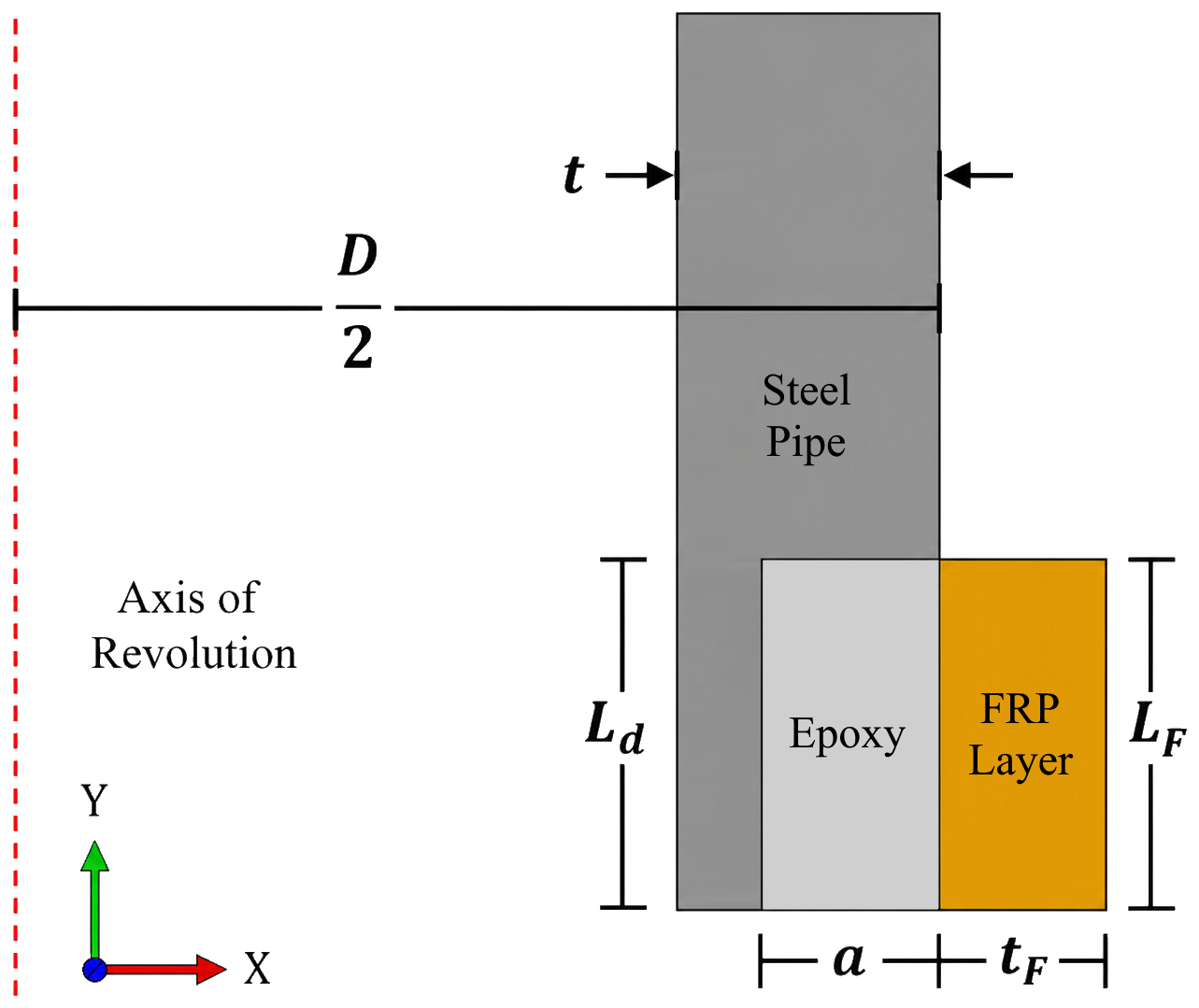
Figure 1Axisymmetric FE model and geometric parameters of the FRP-repaired corroded steel pipe, showing the steel pipe; epoxy filler; FRP layer; axis of revolution; and key dimensions , t, a, tF, Ld, and LF.
The normalized corrosion depth was varied as , 0.20, 0.30, 0.40, 0.50, and 0.60. Previous work showed that increasing the normalized defect length beyond produced negligible additional influence on the maximum inner-hoop stress (Alhusain, 2026b). Accordingly, the defect length was fixed at to represent a near-saturated critical defect length condition. The FRP repair length was fixed at , corresponding to the minimum repair length that fully covered the defect. Previous work also showed that extending the FRP repair beyond the defect length produced only a marginal additional reduction in the maximum inner-hoop stress (Alhusain, 2026a). Therefore, was adopted as a conservative full-coverage repair condition. These fixed values allowed the effects of the defect depth, pipe geometry, and FRP orthotropic stiffness level on the required normalized repair thickness to be isolated.
Table 1Simulation matrix and fixed geometric and/or loading parameters.
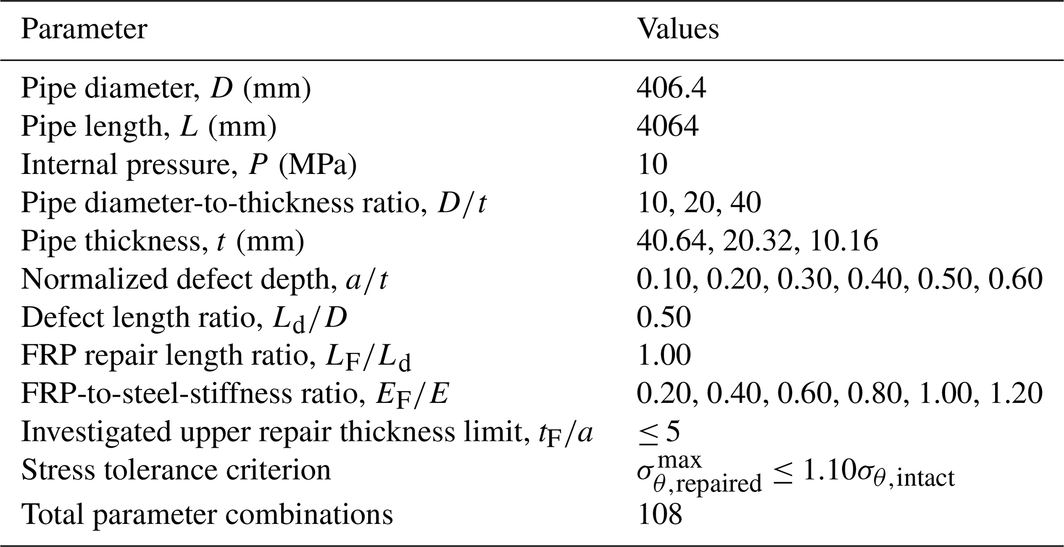
The FRP layer was represented using a normalized orthotropic stiffness model in which the overall stiffness level was varied through the stiffness ratio , where EF is the FRP hoop direction modulus, and E is the elastic modulus of the steel pipe. Six stiffness ratios were considered: , 0.40, 0.60, 0.80, 1.00, and 1.20. The parameter was indexed by the hoop direction modulus, whereas the remaining elastic and shear moduli were scaled proportionally to preserve the relative anisotropy of the reference FRP material. The complete simulation matrix and fixed geometric and/or loading parameters are listed in Table 1.
For each combination of , , and , the required value of was determined by iteratively adjusting the FRP thickness until the maximum inner-hoop stress in the repaired steel pipe satisfied the adopted stress tolerance criterion:
where is the maximum inner-hoop stress in the repaired steel pipe, and σθ,intact is the corresponding maximum inner-hoop stress in the intact pipe with the same ratio. The 10 % stress tolerance criterion was adopted following previous work by Alhusain (2026a), in which the same criterion was used for preliminary carbon-fiber-reinforced polymer (CFRP) repair sizing of corroded steel pipelines. More generally, assessing repair effectiveness relative to the corresponding intact structural response is consistent with previous FRP rehabilitation studies. For example, George et al. (2021) evaluated repair performance using a strength regain ratio referenced to the intact member and reported full recovery of the intact capacity in most cases and approximately 90 % recovery for the pure axial-compression specimens. Accordingly, the present criterion was adopted as a consistent benchmark requiring substantial recovery toward the intact-pipe stress response rather than as a code-prescribed acceptance requirement.
For the feasible repaired cases, the selected values reduced the maximum inner-hoop stress to approximately 9.5 %–10 % above the corresponding intact-pipe stress, confirming that the reported repair thicknesses were close to the target tolerance rather than being substantially over-conservative. An upper bound of was adopted to delimit the repair thickness search rather than to define an absolute physical feasibility limit. For the deepest defect considered in this study, , this upper bound corresponds to an FRP thickness equal to 3 times the pipe wall thickness. Therefore, the selected limit provides a sufficiently broad range for preliminary repair sizing while avoiding an excessively large composite buildup. Cases for which the stress recovery criterion was not satisfied within were classified as having indeterminate feasibility (IF), indicating that their feasibility beyond the investigated thickness range was not evaluated. The resulting dataset was used to evaluate repair feasibility; quantify the effects of , , and on the required FRP thickness; and develop a compact empirical correlation for preliminary repair thickness estimation. The complete FE-derived repair thickness data used to construct the design maps are provided in the Supplement.
2.2 Finite-element modeling
2.2.1 Material properties
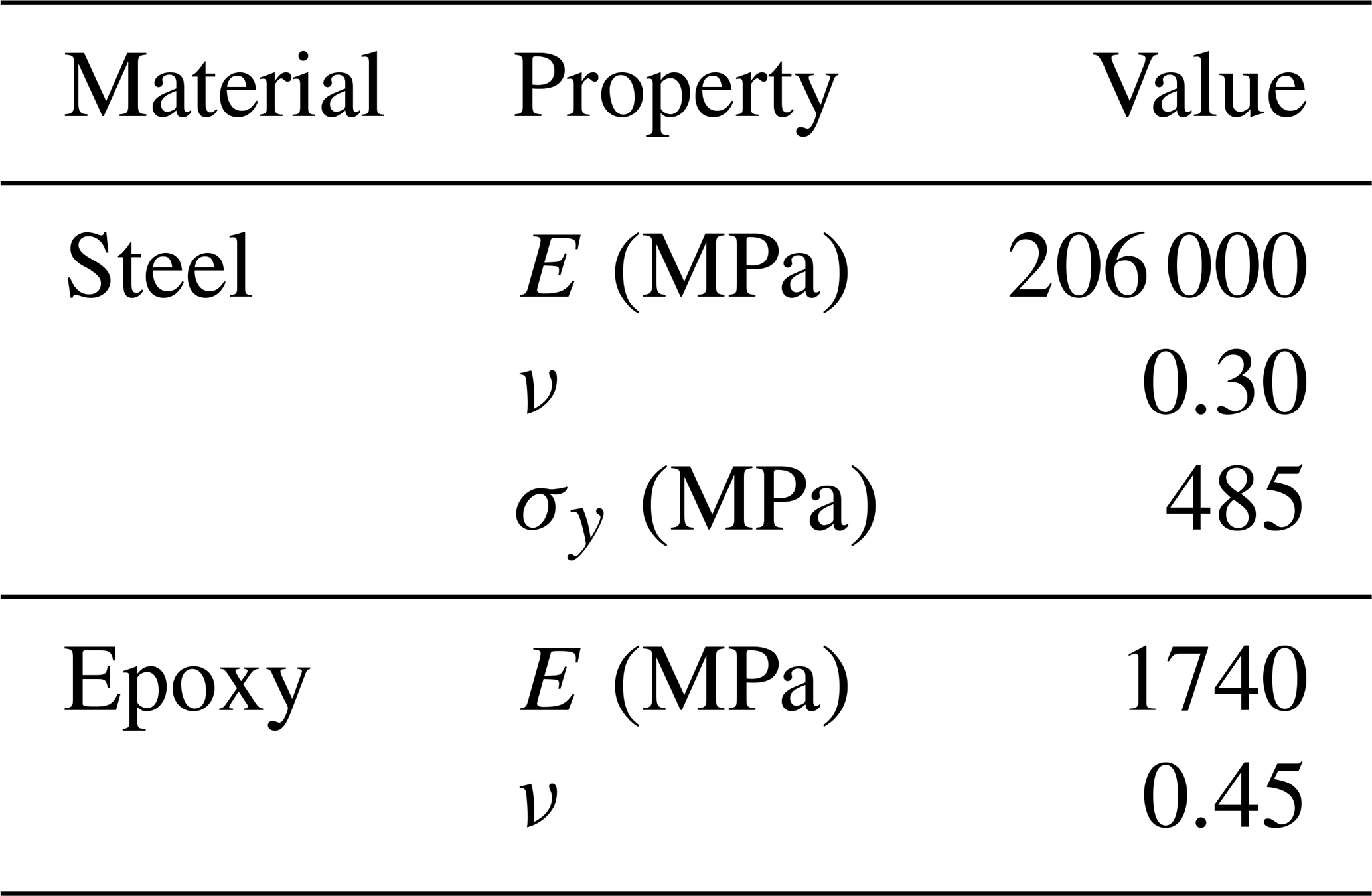
The steel pipe and epoxy filler were modeled as isotropic linear elastic materials. The steel pipe was taken as API 5L X70, with an elastic modulus of E = 206 000 MPa, a Poisson's ratio of ν=0.30, and a specified minimum yield strength of 485 MPa (American Petroleum Institute, 2018). The maximum von Mises stress recorded within the investigated simulation matrix was 401.5 MPa, occurring for , , and at the investigated upper repair thickness limit of . Since this maximum stress remained below the specified minimum yield strength of the X70 steel, linear elastic material behavior was adopted for the steel throughout the parametric study. The epoxy filler was assigned an elastic modulus of E = 1740 MPa and a Poisson's ratio of ν=0.45. The material properties are listed in Table 2.
Table 2Mechanical properties of the steel pipe and epoxy filler used in the FE model (American Petroleum Institute, 2018; Anasiewicz and Kuczmaszewski, 2022; Kar Sing et al., 2018).
The FRP repair layer was modeled as an orthotropic elastic material to represent the directional stiffness of the fiber-reinforced repair systems. Since the objective of this study was to develop a normalized stiffness-based repair thickness framework rather than to evaluate one specific commercial laminate, the FRP stiffness was varied parametrically through the ratio , where EF is the hoop direction modulus of the FRP layer, and E is the elastic modulus of the steel pipe. The hoop direction was assigned as the fiber-dominated material direction, such that E3=EF. Although is defined using the hoop-direction modulus, it represents the overall orthotropic stiffness level of the FRP in the present parametric model because E1,E2, and the shear moduli were scaled proportionally with E3. Thus, should be interpreted as an orthotropic stiffness-scaling parameter indexed by the hoop direction modulus rather than as an independent variation of hoop stiffness alone.
Table 3Orthotropic FRP properties corresponding to the investigated ratios.
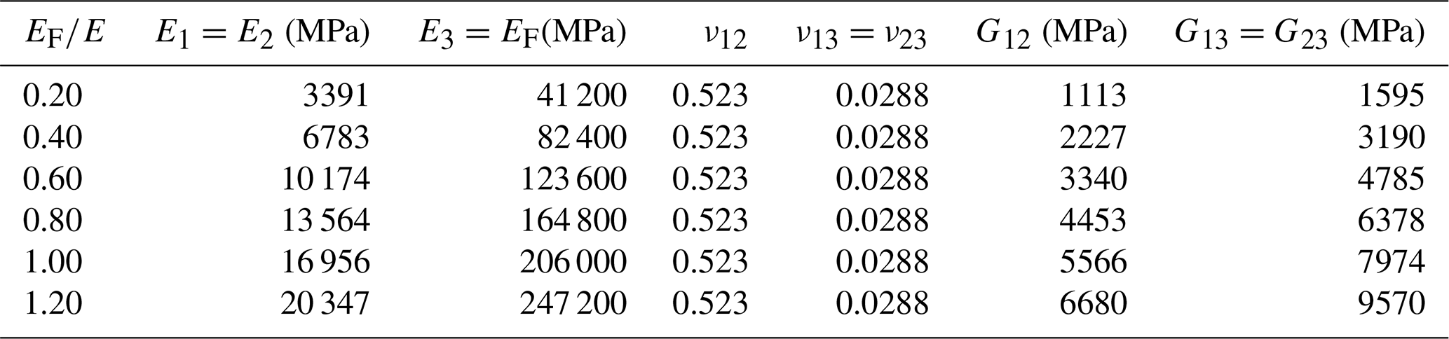
Six stiffness ratios were considered: , 0.40, 0.60, 0.80, 1.00, and 1.20. The orthotropic constants corresponding to these stiffness ratios were generated from the reference CFRP material properties, where the hoop direction modulus was E3 = 165 000 MPa, with E1=E2 = 13 580 MPa, G12 = 4458 MPa, G13=G23 = 6386 MPa, ν12=0.523, and . These reference CFRP properties were used as the baseline orthotropic stiffness pattern. For each target , the elastic and shear moduli were scaled proportionally to match the corresponding hoop direction modulus, whereas the Poisson's ratios were kept constant. The steel modulus was used only to define the non-dimensional stiffness ratio , and the FRP constants were not derived from steel properties. This approach allowed the repair layer to represent a family of FRP systems with different overall orthotropic stiffness levels while preserving the relative anisotropy of the reference material. The corresponding FRP properties used in the FE models are presented in Table 3.
The selected values were not intended to represent specific commercial FRP products. However, they provide an approximate link to the common FRP stiffness classes. Since the steel modulus was E = 206 000 MPa, the investigated ratios = 0.20–1.20 correspond to hoop direction FRP moduli of approximately 41.2–247.2 GPa. The lower end of this range is comparable to the low-stiffness glass-fiber-based repair systems, whereas the upper range is representative of carbon-fiber-based systems with higher hoop stiffness. Intermediate values may represent higher-stiffness glass, basalt, hybrid, or lower-modulus carbon FRP systems, depending on the laminate architecture and fiber volume fraction. Therefore, the stiffness ratios should be interpreted as normalized orthotropic stiffness levels indexed by the hoop direction modulus rather than as independent variations of hoop stiffness or direct assignments to specific FRP materials.
In the axisymmetric model, the FRP material orientation was defined such that material direction 3 corresponded to the circumferential (hoop) direction. Since E3=EF, increasing increased the circumferential stiffness of the repair layer, which is the dominant stiffness component for resisting pressure-induced hoop deformation. However, the remaining elastic and shear moduli were increased proportionally. Therefore, the effects attributed to represent changes in the overall orthotropic stiffness level while maintaining the relative anisotropy of the reference FRP material.
2.2.2 Boundary conditions and loading
The FE model was analyzed using an axisymmetric formulation, where the vertical dashed line shown in Fig. 2 represents the axis of revolution. The model represented half of the pipe length, and an axial symmetry condition was applied at the mid-length plane. This boundary condition was imposed by constraining the axial displacement at the symmetry plane, such that uy=0, as shown in Fig. 2. Radial displacement was not constrained at this plane, allowing the pipe wall, epoxy filler, and FRP layer to expand freely under internal pressure. This allowed the model to represent a fully repaired pipe while reducing the computational domain.
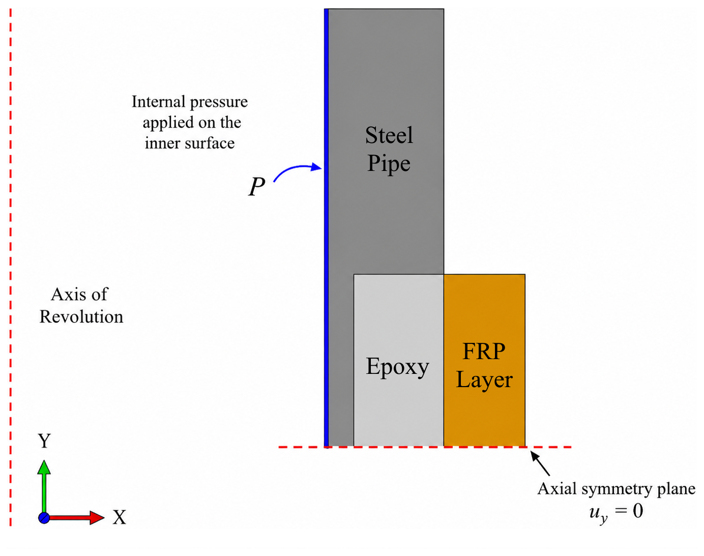
Figure 2Loading and boundary conditions used in the axisymmetric FE model, showing the internal pressure P applied along the inner steel surface and the axial symmetry condition uy=0 imposed at the mid-length plane.
Internal pressure was applied to the inner surface of the steel pipe. The pressure was applied normal to the internal wall and directed radially outward. A constant internal pressure of P = 10 MPa was used throughout the parametric study. The pipe ends were treated as open-ended; therefore, no closed-end axial pressure load was applied. This condition was selected to isolate the pressure-induced hoop stress response and the corresponding stress reduction provided by the FRP repair layer.
The model was analyzed using ABAQUS/Standard with a static general analysis step. Geometric nonlinearity was included to account for the deformation effects during pressurization, although the material response remained within the elastic range under the applied operating pressure. The default ABAQUS/Standard equilibrium convergence controls were used for the static analysis, and all simulations converged without numerical instability.
The epoxy filler and FRP repair layer were bonded to the steel pipe, and perfect interfacial contact was assumed between the adjacent materials. Accordingly, displacement compatibility was maintained at the steel–epoxy and epoxy–FRP interfaces using tie constraints. This assumption allowed the influence of the FRP stiffness and thickness on the hoop stress redistribution to be evaluated without introducing additional uncertainty from interface damage or debonding.
2.2.3 Stress evaluation
The repair performance was evaluated based on the hoop stress response of the steel pipe. Since the applied internal pressure primarily produces circumferential stress in the pipe wall, the hoop stress component, σθ, was selected as the main response quantity. In the axisymmetric FE model, this stress component corresponds to the circumferential stress output.
For each repaired configuration, the maximum hoop stress along the inner surface of the steel pipe was extracted and used as the governing stress measure. The inner surface hoop stress was selected because it directly represents the pressure-side stress demand in the remaining steel wall and provides a consistent basis for comparing the intact, corroded, and repaired configurations.
The repair effectiveness was evaluated using the stress tolerance criterion defined in Sect. 2.1. According to this criterion, the repaired pipe was considered to be acceptable when the maximum inner-hoop stress in the repaired steel pipe was reduced to within 10 % above the corresponding intact-pipe value for the same ratio. Therefore, the intact-pipe stress was evaluated separately for each pipe geometry, ensuring that the repair assessment was normalized with respect to the corresponding uncorroded baseline.
For each of the 108 parameter combinations of , , and , the required FRP thickness was determined using a manual adaptive search procedure. The initial value of was selected based on the trends observed in previously completed parameter combinations rather than using an arbitrary fixed starting value. When the repaired stress was substantially different from the target value, was adjusted using increments or decrements of 0.5. As the stress approached the target, the thickness step was reduced to 0.1, and, for , the step was further reduced to 0.01. No interpolation between successive thickness values was used; each reported corresponds to an explicitly analyzed FE configuration. The search was terminated when the maximum inner-hoop stress in the repaired steel pipe was between 9.5 % and 10 % above the corresponding intact-pipe stress, and the associated was recorded as the required repair thickness. For cases in which the unrepaired corroded pipe already satisfied the 10 % criterion, no FRP layer was applied, and the case was classified as no repair (NR). For cases in which the criterion remained unsatisfied at the investigated upper limit of , the search was terminated, and the case was classified as having indeterminate feasibility (IF). Because the number of thickness iterations varied among parameter combinations, the 108 cases reported in Table 1 represent distinct parameter combinations rather than the total number of individual FE analyses.
2.3 Mesh and convergence analysis
A structured axisymmetric mesh was generated for the repaired pipe model, as illustrated in Fig. 3. The steel pipe, epoxy filler, and FRP repair layer were discretized using eight-node biquadratic axisymmetric quadrilateral elements (CAX8). These second-order elements were selected to improve the representation of stress gradients through the pipe wall and across the repaired region. A fine mesh was used in the corrosion defect, epoxy filler, and FRP repair regions to capture the local stress gradients near the repaired defect. A magnified view of the repair region is shown in Fig. 3, illustrating the mesh distribution across the steel pipe, epoxy filler, and FRP layer.
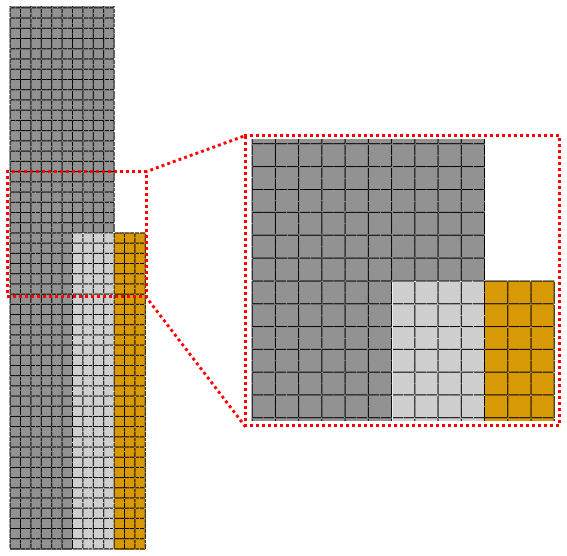
Figure 3Structured CAX8 axisymmetric finite-element mesh of the repaired pipe model showing the global mesh and a magnified view of the corrosion defect, epoxy filler, and FRP repair layer.
Table 4Mesh convergence study for the representative repaired pipe model with , , and .
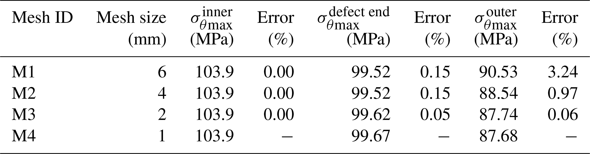
A mesh convergence study was performed using a representative repaired pipe model with , , and . Four mesh sizes were examined, ranging from 6 to 1 mm, as summarized in Table 4. The convergence assessment was based on the maximum hoop stress at three locations: the inner steel surface, defect end region, and outer steel surface. The defect end stress was included as a local convergence indicator because this region contains the strongest geometric discontinuity and stress gradient in the repaired model. The percentage error was calculated relative to the finest mesh (M4).
The maximum inner-hoop stress was insensitive to mesh refinement and remained constant at 103.9 MPa for all investigated mesh sizes. The defect end hoop stress also showed excellent convergence, with the error decreasing from 0.15 % for the 6 and 4 mm meshes to 0.05 % for the 2 mm mesh. The outer surface hoop stress exhibited the largest mesh sensitivity for the coarsest mesh, with an error of 3.24 % for M1. However, this error decreased to 0.97 % for M2 and only 0.06 % for M3.
Based on these results, a 2 mm mesh was selected for the parametric study. This mesh produced the same maximum inner-hoop stress as the finest 1 mm mesh and resulted in errors of only 0.05 % and 0.06 % for the defect end and outer surface hoop stresses, respectively. Therefore, further refinement to 1 mm provided negligible improvement while increasing the computational cost.
2.4 Model verification and literature-based validation
Before conducting the parametric study, the axisymmetric FE model was verified using a closed-form multilayer thick cylinder solution. Verification was performed to confirm that the FE model correctly reproduced the elastic-hoop stress response of a bonded steel–epoxy–FRP system under internal pressure. A three-layer cylindrical configuration consisting of a steel pipe, epoxy filler, and external repair layer was considered. The pipe was treated as open-ended, consistent with the FE boundary conditions, and perfect bonding was assumed between the adjacent layers.
This verification was intended to confirm the implementation of the bonded multilayer elastic cylinder model, including pressure loading, material layering, and interfacial compatibility. It was not used as a validation of the local corrosion defect response because the analytical Lamé solution does not represent geometric wall loss discontinuities.
An analytical solution was obtained using the Lamé thick-cylinder theory (Timoshenko et al., 1970). For each layer, the radial and hoop stresses were expressed as
where r is the radial coordinate, and A and B are the Lamé constants for the corresponding layer. The constants were evaluated using the pressure boundary conditions at the inner and outer radii and the interface pressures between adjacent layers. Since the model represents an open-ended pipe, the radial displacement used for enforcing interfacial compatibility was written as
where E and ν are the elastic modulus and Poisson's ratio of the layer. The unknown interface pressures were obtained by satisfying the displacement continuity at the steel–epoxy and epoxy–FRP interfaces.
The verification was carried out for , 20, and 40 while keeping the pipe diameter constant at D = 406.4 mm. The corresponding pipe thicknesses were 40.64, 20.32, and 10.16 mm, respectively. For the verification analysis, both the epoxy and FRP layer thicknesses were set to be equal to 20 % of the pipe wall thickness. The FE model retained the orthotropic FRP properties corresponding to , with a hoop direction modulus of E3=EF = 82 400 MPa. For the analytical multilayer-cylinder solution, the FRP layer was represented using an equivalent isotropic elastic modulus of 82 400 MPa and a Poisson's ratio of 0.30. This equivalent isotropic representation was used only in the analytical calculation; the FRP material in the FE model remained orthotropic. The inner and outer surface hoop stresses in both the steel pipe and FRP layer were extracted from the FE model and compared with the analytical results.
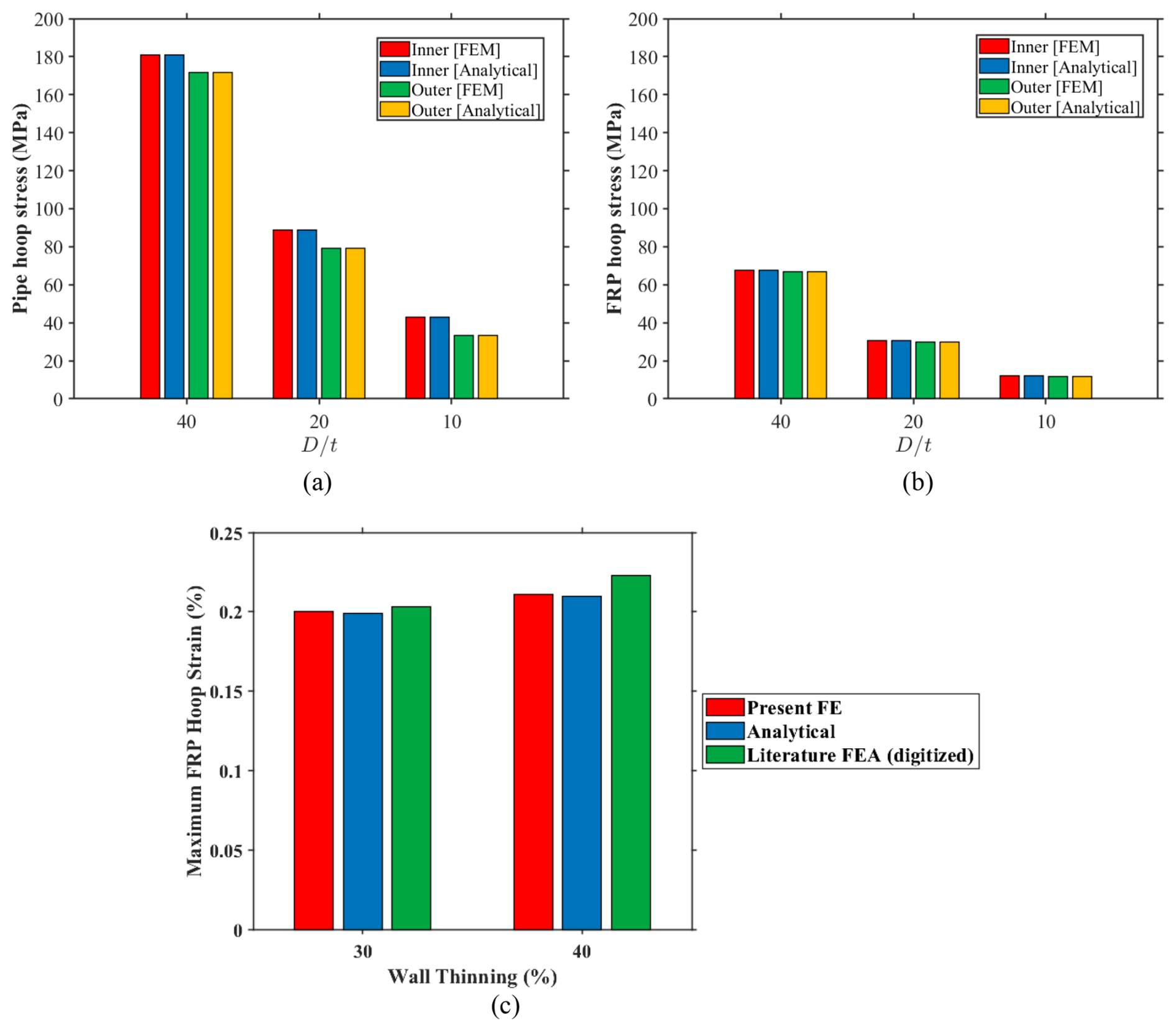
Figure 4FE model verification: (a) steel and (b) FRP hoop stresses compared with the analytical multilayer solution and (c) FRP hoop strain compared with digitized FEA data from Saeed et al. (2014).
As shown in Fig. 4, the FE predictions were in close agreement with the analytical solution for all investigated ratios. The hoop stresses on the inner and outer surfaces of the steel pipe were nearly identical between the two approaches, and a similar agreement was observed for the FRP layer. This agreement confirms that the axisymmetric FE model accurately captures the elastic stress distribution and load transfer in the bonded multilayer systems. Therefore, the verified model was used for the subsequent parametric investigation of the required normalized FRP repair thickness.
To provide an additional literature-based validation for a repaired pipe containing actual wall thinning, the validation procedure previously reported by Alhusain (2026a) was adopted, in which selected axisymmetric composite-repair cases from Saeed et al. (2014) were reproduced. Two zero-live-pressure cases with circumferential wall thinning of 30 % and 40 % were reproduced using the pipe geometry, repair thicknesses, composite properties, and design pressure reported in the reference study. Saeed et al. employed a two-dimensional axisymmetric FE model and evaluated the composite response at a design pressure of 27.25 MPa. The present FE model predicted maximum FRP hoop strains of approximately 0.200 % and 0.211 % for the 30 % and 40 % wall-thinning cases, respectively. The corresponding analytical values were approximately 0.199 % and 0.210 %, while the digitized literature FEA values were approximately 0.203 % and 0.223 %, as shown in Fig. 4c. The present FE predictions therefore differed from the digitized literature values by approximately 1.5 % and 5.4 %, respectively, indicating a reasonable agreement. Although the analytical and literature-based benchmarks do not reproduce the finite defect end geometry, the local stress response was assessed through the mesh convergence study in Sect. 2.3, where the selected 2 mm mesh differed from the finest 1 mm mesh by only 0.05 % in the defect end hoop stress.
2.5 Development of the proposed correlation
After determining the required FRP thickness from the FE simulations, the resulting dataset was used to develop a compact empirical correlation for estimating the normalized repair thickness, . The correlation was formulated in terms of the three main non-dimensional parameters considered in the parametric study: the FRP-to-steel-stiffness ratio , the normalized defect depth , and the pipe diameter-to-thickness ratio . The objective was to define a design-oriented functional form that captures the main FE trends and that can be used for the preliminary estimation of the required FRP repair thickness.
The proposed functional form was selected based on the trends observed in the FE results. The required normalized repair thickness decreased with increasing , increased with increasing , and varied with in a manner dependent on the defect depth. Accordingly, the following general correlation was adopted:
where C, n, p, and q are the fitting constants. The reference values and were used to normalize the correlation around representative values within the investigated parameter range.
The fitting constants were obtained using MATLAB by minimizing the difference between the FE-derived and predicted values of . Only feasible repaired cases were included in the fitting dataset. Cases classified as no repair were excluded because they correspond to , while IF cases were excluded because the stress recovery criterion was not achieved within the investigated upper limit of . The shallowest defect cases with were also excluded from the fitting and error evaluation because several of these cases required no repair or very small repair thicknesses, which can distort a power-law correlation intended for finite repair demand.
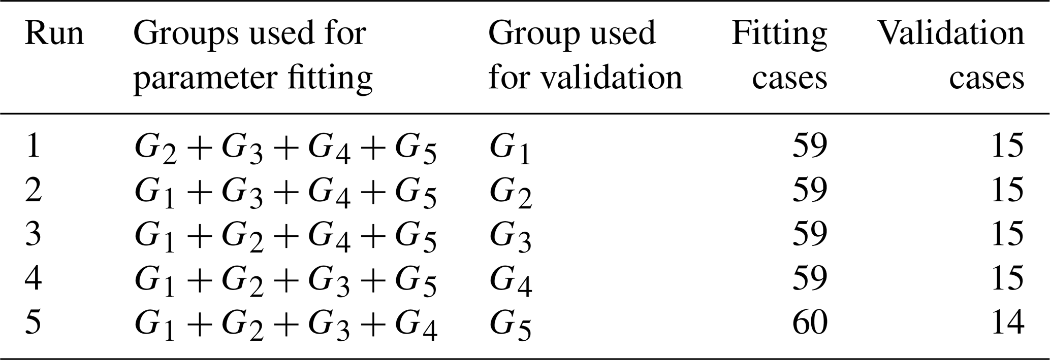
To assess the predictive robustness of the proposed correlation form, 5-fold cross-validation was performed using the 74 eligible FE cases. The cases were randomly divided into five approximately equal groups, G1–G5, containing 14–15 cases each. In each run, four groups were used to refit the correlation coefficients C, n, p, and q, while the remaining group was withheld for validation, as summarized in Table 5. This procedure ensured that every case was used once for validation. The overall cross-validation statistics were calculated from the combined held-out predictions. Detailed group assignments, fold-specific fitted coefficients, and validation statistics are provided in the Supplement. The fold-specific coefficients were used only for cross-validation, whereas the final correlation reported in Sect. 3.4 was fitted using the complete set of 74 eligible FE cases.
Table 5The 5-fold cross-validation scheme used to evaluate the proposed correlation.
The optimized constants and predictive performance of the final correlation are presented in Sect. 3.4. The proposed correlation was developed for the parameter ranges investigated in this study and is intended as a preliminary thickness estimation tool for elastic-hoop stress recovery. Therefore, its use should be limited to the fitted parameter range and should not be interpreted as a substitute for detailed design checks involving FRP failure, interfacial debonding, installation constraints, or long-term durability.
3.1 Overview of required FRP thickness trends and repair feasibility
The overall repair response was first examined by comparing the representative hoop stress distributions before and after repair. Figure 5 shows the hoop stress contours for the case and , including the unrepaired pipe and two repaired configurations with different FRP stiffness ratios. The unrepaired pipe exhibited a significantly higher hoop stress field near the corrosion defect, confirming the stress amplification caused by the local wall thickness reduction. After repair, the steel-hoop stress was substantially reduced, and the two repaired cases produced similar stress distributions despite using different FRP stiffness ratios and repair thicknesses.
For the repaired cases shown in Fig. 5, the lower-stiffness repair with required a larger normalized thickness of , whereas the higher-stiffness repair with required only . The similarity between the repaired stress fields indicates that comparable elastic repair performances can be obtained using different FRP systems when the repair thickness is adjusted according to the FRP stiffness. Therefore, primarily controls the amount of repair thickness required to achieve the target stress reduction, which is consistent with previous findings that composite stiffness governs load sharing in repaired steel pipes (Chen et al., 2021; Dumitrescu et al., 2021). In the present cases, once the same stress recovery criterion was satisfied, the repaired steel stress distributions remained broadly similar despite the different stiffness–thickness combinations.
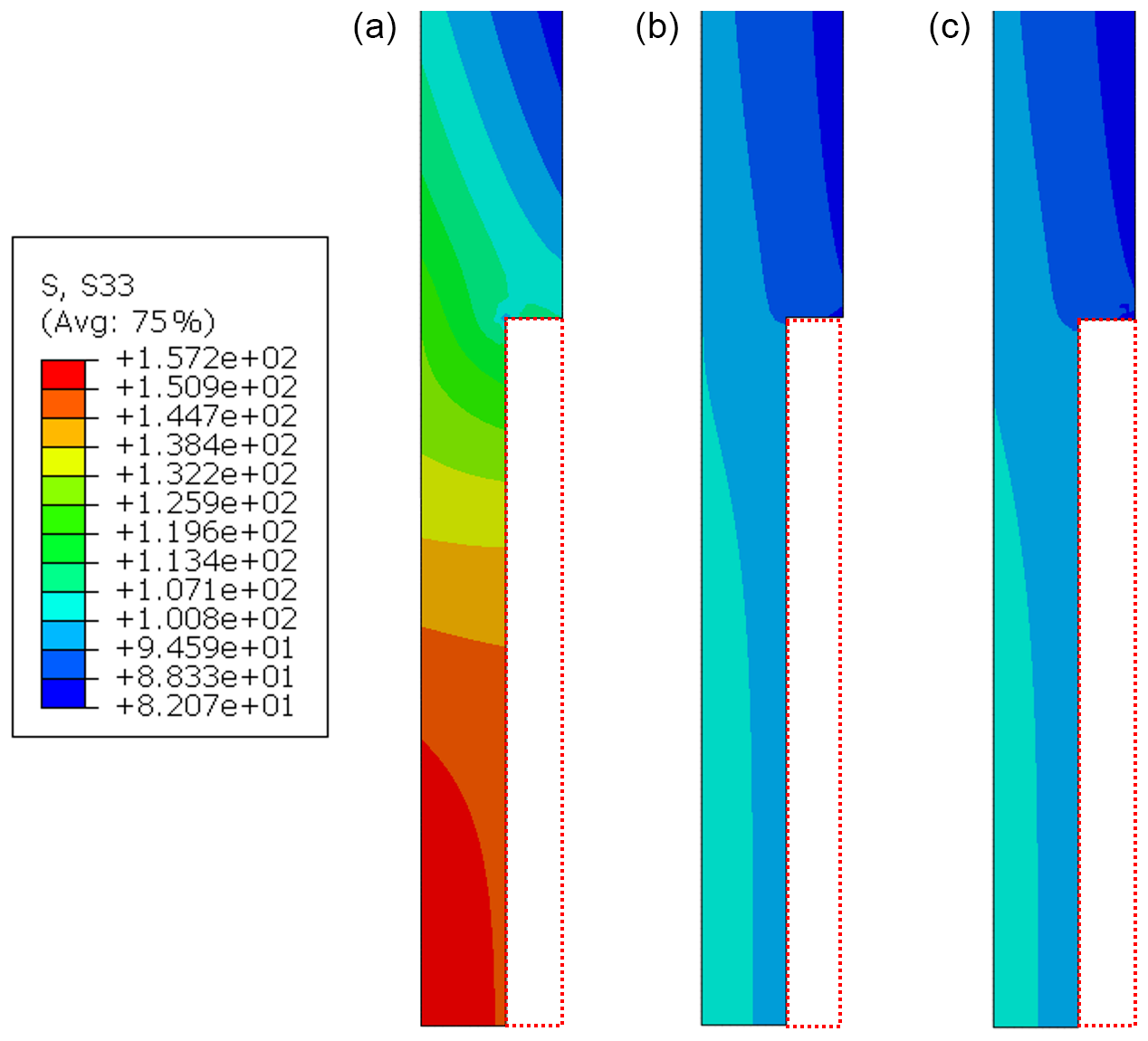
Figure 5Representative hoop stress distributions in the steel pipe for and : (a) unrepaired pipe, (b) repaired pipe with and , and (c) repaired pipe with and .
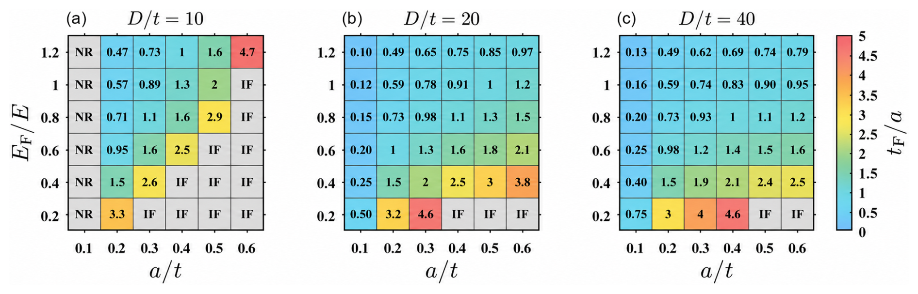
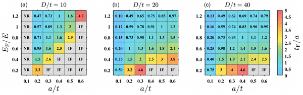
Figure 6Repair feasibility maps showing the required normalized FRP thickness for different ratios: (a) , (b) , and (c) . NR indicates that no repair is required, whereas IF indicates indeterminate feasibility, corresponding to cases in which the stress recovery criterion was not achieved within .
The complete feasibility map is shown in Fig. 6. This figure summarizes the required values for all of the investigated combinations of , , and . Cases marked as NR indicate that the unrepaired corroded pipe already satisfied the 10 % stress tolerance criterion and therefore did not require an FRP repair. Cases marked as IF indicate indeterminate feasibility, meaning that the criterion was not satisfied within the investigated upper limit of . This classification distinguishes between cases in which repair is unnecessary, cases in which the criterion can be satisfied within the investigated thickness range, and cases for which the feasibility beyond this range remains undetermined. Accordingly, the NR and IF classifications are specific to the adopted 10 % stress tolerance criterion and search limit and should not be interpreted as absolute classifications independent of these thresholds. The feasibility map also shows that low-stiffness FRP systems are more likely to reach the investigated upper thickness limit for deeper defects than high-stiffness FRP systems.
The influence of FRP stiffness was particularly evident at , where the stress recovery criterion was satisfied within the investigated thickness range for fewer parameter combinations as the defect depth increased. In contrast, higher stiffness ratios expanded the range of configurations for which the criterion was satisfied and reduced the required normalized thickness over a wider range of and . These results demonstrate that the ability to satisfy the adopted stress recovery criterion within the investigated thickness range depends on the combined effects of defect severity, pipe geometry, and FRP stiffness.
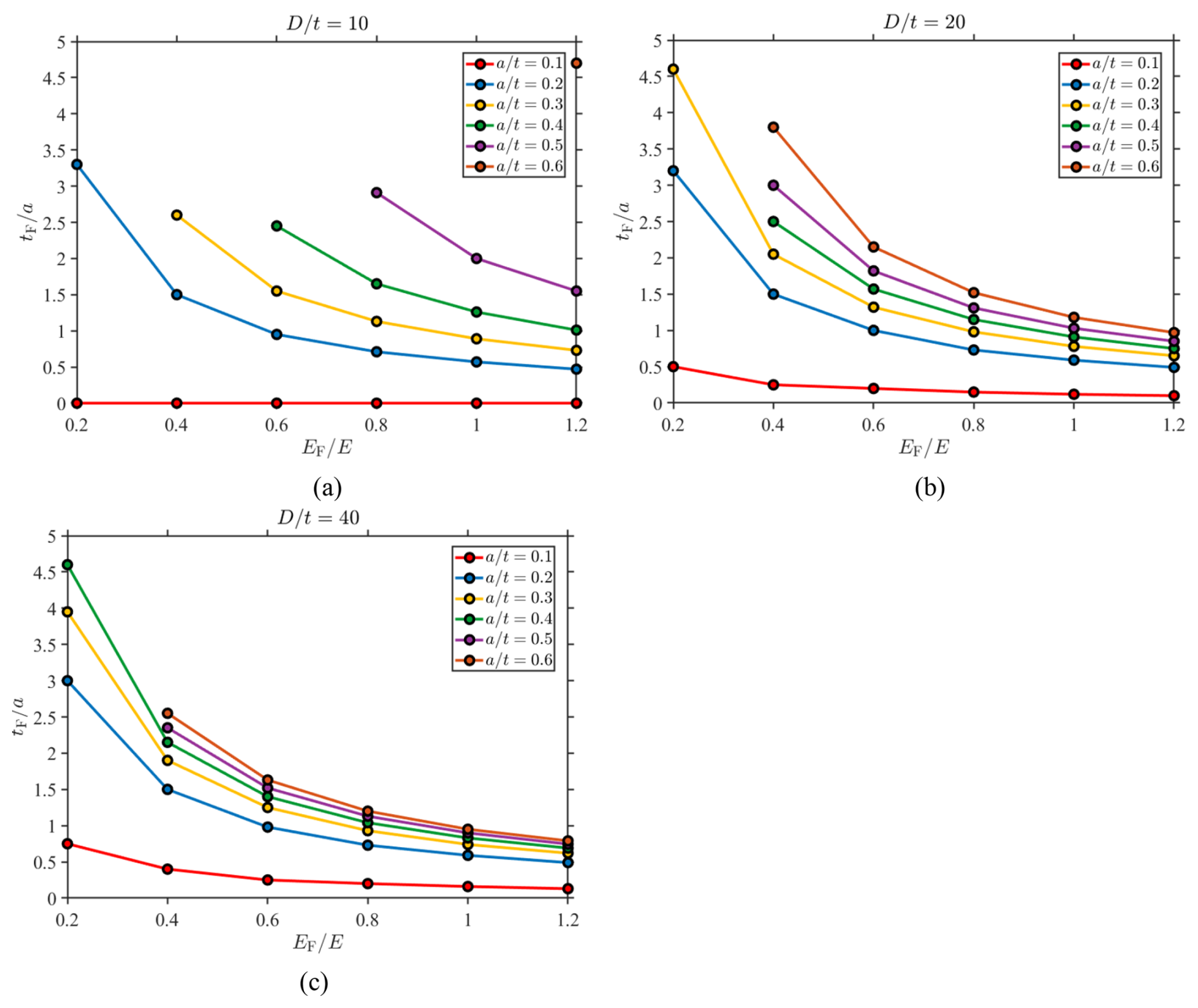
Figure 7Effect of FRP stiffness ratio on the required normalized repair thickness : (a) , (b) , and (c) .
3.2 Effect of FRP stiffness ratio on required repair thickness
The influence of the FRP-to-steel-stiffness ratio, , on the required normalized repair thickness is shown in Fig. 7. For all of the investigated ratios, increasing reduced the required . This trend is expected because a stiffer FRP layer provides greater circumferential resistance to pressure-induced deformation, allowing the target reduction in steel-hoop stress to be achieved with a smaller repair thickness. This behavior is consistent with previous findings, which show that the stiffness of the composite repair layer governs load sharing between the steel pipe and the external repair system (Ansari Sadrabadi et al., 2022; Duell et al., 2008; Lim et al., 2019).
For , the repair demand was highly dependent on both the defect depth and FRP stiffness, as shown in Fig. 7a. Shallow defects with did not require repair because the unrepaired pipe already satisfied the 10 % stress tolerance criterion. For larger defects, however, the required decreased markedly as increased. For example, at , the required thickness decreased from at to at . For deeper defects, some low-stiffness cases exhibited indeterminate feasibility within the investigated upper limit of , indicating that increasing repair stiffness becomes increasingly important as the defect severity increases.
A similar reduction in the required repair thickness was observed for , as shown in Fig. 7b. For this geometry, feasible repairs were obtained over a wider range of defect depths and stiffness ratios. The required decreased consistently with increasing for all defect depths. At , the required normalized thickness decreased from at to at . This behavior confirms that higher-stiffness FRP systems can substantially reduce the repair thickness required to satisfy the same stress criterion.
For , shown in Fig. 7c, the effect of remained clear, but the reduction in became more gradual at higher stiffness ratios. The curves show a steep decrease between and 0.6, followed by smaller reductions as increased further. This indicates that the benefit of increasing the FRP stiffness is strongest when moving from low-stiffness to moderate-stiffness repair systems, while further increases in stiffness produce progressively smaller reductions in the required normalized thickness.
Overall, Fig. 7 confirms that is one of the dominant parameters controlling the required repair thickness. The decrease in with increasing was consistent across all pipe geometries and defect depths. However, the magnitude of this reduction depended on and , showing that FRP stiffness cannot be evaluated independently from defect severity and pipe geometry. These results support the use of a normalized stiffness-based correlation, in which , , and are considered simultaneously.
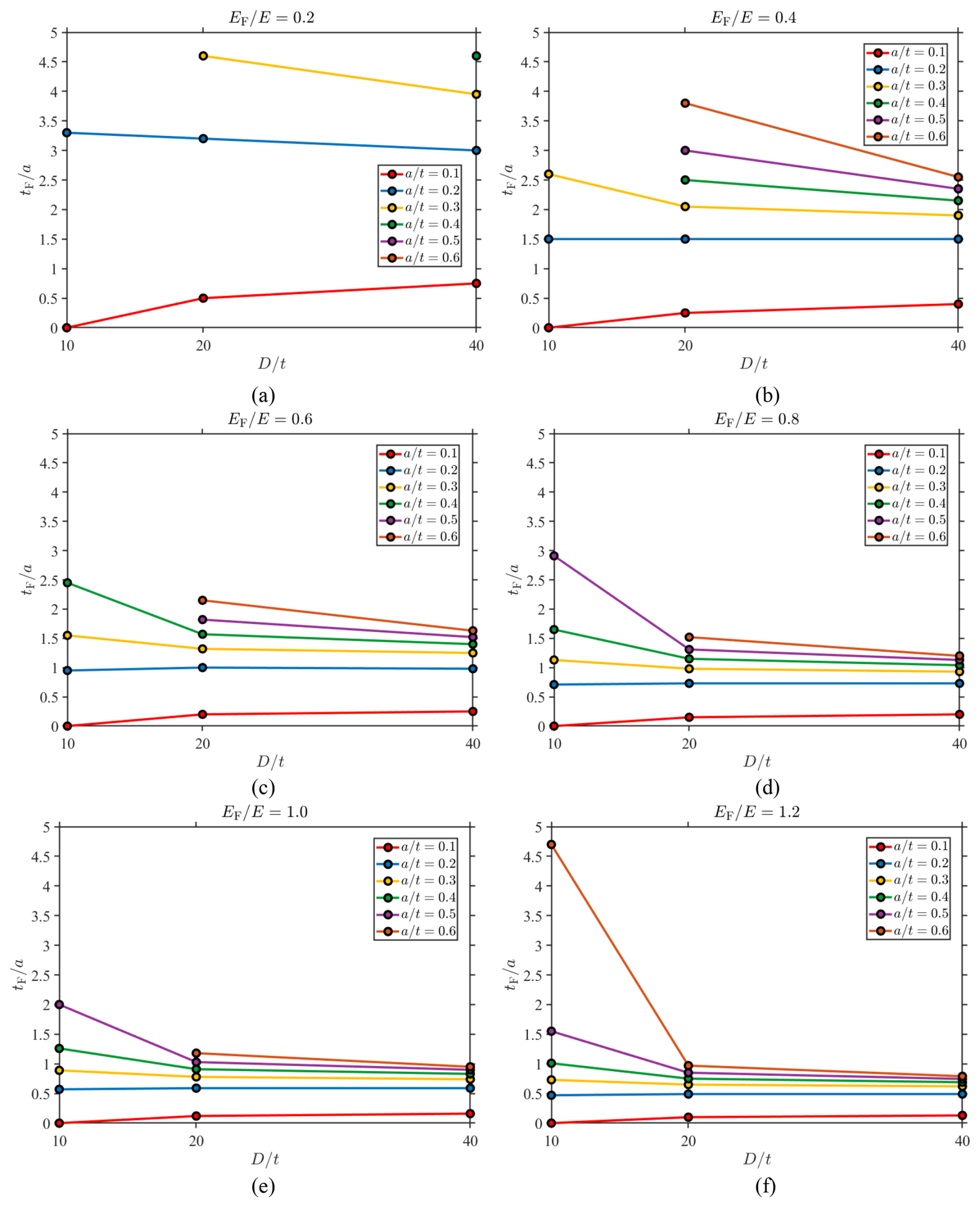
Figure 8Effect of pipe diameter-to-thickness ratio on the required normalized repair thickness for different FRP stiffness ratios: (a) , (b) , (c) , (d) , (e) , and (f) .
3.3 Effect of pipe slenderness on required repair thickness
The effect of the pipe diameter-to-thickness ratio, , on the required normalized FRP thickness is shown in Fig. 8. Unlike the effect of FRP stiffness, the influence of was more dependent on the defect depth and stiffness ratio. This indicates that pipe slenderness affects the repair demand through its influence on the stress recovery target and the remaining wall stiffness. Previous numerical work on FRP-reinforced steel pipes has similarly shown that pipe dimensions, including diameter and wall thickness, influence the effectiveness of composite reinforcement (Elchalakani et al., 2017; Li et al., 2022; Sebeay and Ahmed, 2023).
For low FRP stiffness, the effect of was more pronounced, and the feasible repair region was limited. At , shown in Fig. 8a, several deeper-defect cases exhibited indeterminate feasibility within the investigated upper thickness limit. For the feasible cases, the required did not vary monotonically in the same way for all defect depths. For shallow defects, the thicker-pipe case was less demanding and could even require no repair. However, for larger defects, the stress recovery criterion was not achieved for some low-stiffness configurations within the investigated thickness range.
As the stiffness ratio increased, the influence of decreased. For and 0.6, shown in Fig. 8b and c, the required generally decreased as increased for moderate and deep defects. This trend suggests that, within the investigated range, thinner-walled pipes require smaller normalized repair thicknesses once the repair is feasible. However, this does not imply that thinner pipes are less stressed in terms of absolute values. Instead, it reflects how the normalized repair thickness required to restore the stress to the corresponding intact-pipe baseline changes with the wall slenderness.
For higher stiffness ratios, , 1.0, and 1.2, shown in Fig. 8d–f, the curves became flatter for most defect depths. This indicates that increasing the FRP stiffness reduces the sensitivity of the required thickness to . At high stiffness ratios, the FRP layer provides sufficient circumferential stiffness such that the required becomes controlled more by the defect depth than by pipe slenderness. Nevertheless, the deepest defect cases still showed visible sensitivity to , especially for and 0.6.
The shallow-defect cases exhibited different behaviors compared to the deeper defects. For , some configurations required no repair, particularly for . This occurs because the remaining steel wall is sufficiently stiff for shallow corrosion, such that the unrepaired pipe can remain close to the 10 % stress tolerance criterion. As increases, the same normalized defect depth corresponds to a thinner pipe wall, and the no-repair condition becomes less common. This explains why the shallow-defect curves may increase slightly with , while deeper-defect curves generally decrease or become less sensitive as increases.
Overall, Fig. 8 shows that has a secondary but important influence on the repair thickness. Its effect is strongest for low-stiffness FRP systems and deeper defects, where the feasibility of repair can change depending on the pipe geometry. At higher FRP stiffness ratios, the required thickness becomes less sensitive to , supporting the conclusion that repair stiffness can reduce the geometric dependence of the required FRP thickness.
3.4 Evaluation and cross-validation of the proposed correlation
The fitting procedure described in Sect. 2.5 was applied to the FE-derived repair thickness dataset to obtain the constants for the proposed empirical correlation. The optimized constants were obtained as C=0.577, n = −1.063, p=0.876, and q = −1.850. Therefore, the final proposed correlation is expressed as
The correlation structure reflects the main trends observed in the FE results. The negative exponent of indicates that the required normalized repair thickness decreases as the FRP stiffness increases. Because this exponent is close to −1, the required repair thickness is approximately inversely related to the overall orthotropic stiffness level represented by . The positive exponent of confirms that deeper defects require larger normalized repair thicknesses. The final term accounts for the interaction between and the defect depth, allowing the effect of pipe slenderness to vary with rather than being treated as a constant scaling factor.
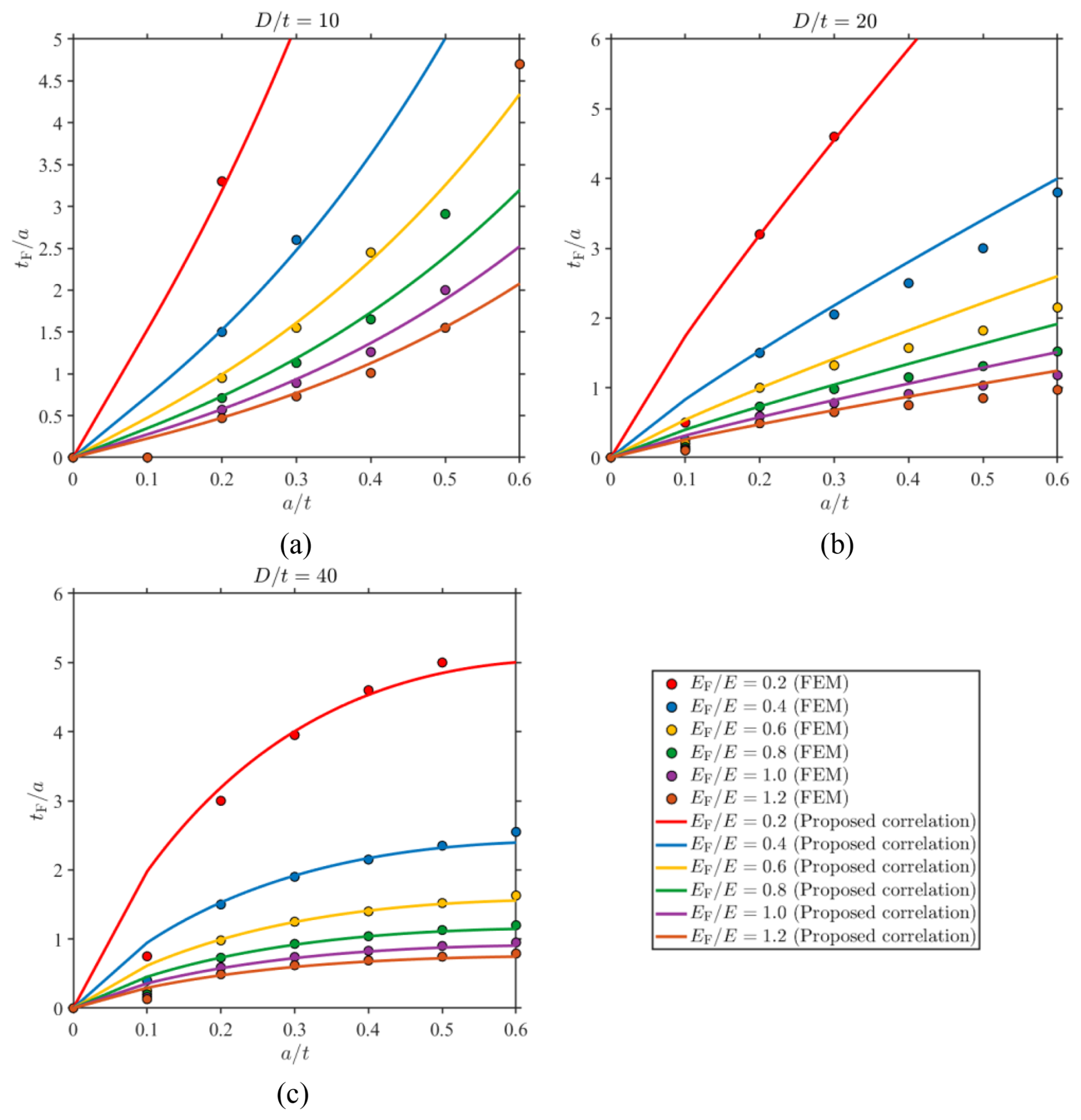
Figure 9Comparison between the FE-derived repair thicknesses and the proposed correlation for different pipe diameter-to-thickness ratios: (a) , (b) , and (c) . The correlation curves below are shown only for visual continuity and lie outside the fitted correlation domain.
Figure 9 compares the FE-derived values with the values predicted by the proposed correlation for , 20, and 40. The markers represent the FE results, and the solid lines represent the proposed correlation. For visual continuity, the correlation curves are extended below ; however, this portion lies outside the fitted correlation domain and was not included in the fitting or error evaluation. For , the correlation captures the rapid increase in the required repair thickness with increasing , particularly for low stiffness ratios. For , the proposed equation follows the FE trends over a wider range of defect depths and stiffness ratios. For , the correlation captures the more gradual increase in required thickness for moderate and high stiffness ratios, as well as the stronger nonlinear response observed for low-stiffness repair systems.
The overall predictive performance of the proposed correlation was further evaluated using the parity plot shown in Fig. 10. Most data points were located close to the one-to-one reference line, indicating good agreement between the FE-derived and predicted values. The agreement was strongest in the moderate repair thickness range, where most feasible cases were found. Larger deviations occurred mainly near the upper repair thickness range, where the response became more sensitive to the low FRP stiffness and proximity to the investigated upper thickness limit.
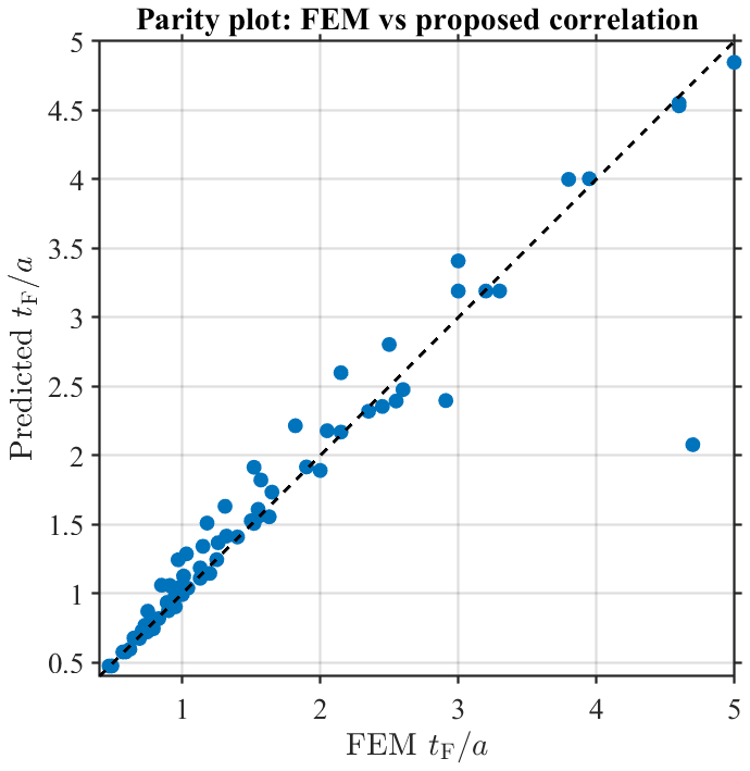
Figure 10Parity plot comparing the FE-derived and predicted normalized repair thickness values obtained from the proposed correlation. The dashed line represents perfect agreement between the FE-derived and predicted values.
The predictive accuracy of the final correlation against the complete fitting dataset was quantified using the coefficient of determination (R2), mean absolute error (MAE), root-mean-square error (RMSE), and mean absolute percentage error (MAPE). The correlation achieved R2 = 0.90, MAE = 0.13, RMSE = 0.34, and MAPE = 7.36 %, indicating good overall agreement with the FE-derived repair thicknesses. To further assess the predictive performance on held-out cases, five-fold cross-validation was performed as described in Sect. 2.5. The combined held-out predictions yielded R2 = 0.86, MAE = 0.14, RMSE = 0.38, and MAPE = 6.71 %. The fold-specific MAPE ranged from 5.41 % to 8.49 %. The comparable error levels obtained for the complete fitting dataset and the held-out cases indicate that the proposed correlation form retains good predictive capability within the investigated parameter space. Detailed cross-validation results are provided in the Supplement.
Overall, Figs. 9 and 10 show that the proposed correlation provides a reasonable preliminary estimate of the required normalized FRP thickness within the investigated parameter range. The correlation is applicable for feasible repair cases within , , and , with and . It should be used as a preliminary thickness estimation tool for elastic-hoop stress recovery, while detailed design should also consider strength limits, FRP failure, interfacial debonding, installation constraints, and long-term durability. Accordingly, the correlation should be interpreted as an interpolation tool within the investigated parameter domain since its predictive accuracy outside these ranges has not been established.
3.5 Practical applicability and limitations of the FE-based thickness maps
The FE-based results presented in this study provide a normalized map of the FRP thickness required to reduce the maximum inner-hoop stress of a corroded steel pipe to within 10 % above the corresponding intact-pipe value. The maps are intended to show how the required normalized repair thickness, , changes with the defect depth, pipe diameter-to-thickness ratio, and FRP orthotropic stiffness level. Therefore, the main use of the results is to support preliminary repair assessment by identifying whether a given corrosion severity can be repaired within a practical thickness range and how the required repair thickness changes when a lower- or higher-stiffness FRP system is used for repair.
The feasibility classification used in this study should be interpreted within the adopted repair criterion and the investigated thickness range. Cases marked as no repair indicate that the unrepaired corroded pipe satisfied the 10 % stress tolerance criterion. Cases marked as IF indicate indeterminate feasibility, meaning that the criterion was not achieved within the investigated upper limit of . This classification does not imply that repair is physically infeasible beyond this limit; rather, repair thicknesses exceeding this range were not considered. In practice, the maximum acceptable repair thickness may depend on the installation method, available wrapping systems, allowable diameter increase, accessibility, and project-specific requirements.
The findings are applicable within the parameter range investigated in the FE study: , for the FE maps, and . The defect length and repair length were fixed at and , respectively. These values were selected based on previous parametric studies rather than as arbitrary fixed conditions. A defect length of represents a near-saturated critical condition because further increases in defect length produced negligible additional influence on the maximum inner-hoop stress (Alhusain, 2026b). Similarly, represents the minimum full-coverage repair condition, while extending the FRP beyond the defect length produced only marginal additional stress reduction (Alhusain, 2026a). Nevertheless, because and were not varied in the present parametric matrix, the thickness maps and correlation should be applied directly only to these fixed ratios. Application to substantially different defect lengths, partial-coverage repairs, or other repair length ratios requires additional analysis.
Several modeling assumptions must be considered. The analysis was limited to the elastic-hoop stress recovery under internal pressure. The present thickness maps were developed specifically for open-ended pipes, for which no closed-end axial pressure load was applied. Accordingly, the predicted values are directly applicable to this loading condition. Closed-ended pipes additionally develop a pressure-induced axial membrane stress, which could modify the local multi-axial stress state and should therefore be assessed separately. The steel pipe and epoxy filler were modeled as linear elastic materials, and the FRP layer was represented using an orthotropic-elastic-stiffness model. Perfect bonding was assumed at the steel–epoxy and epoxy–FRP interfaces; therefore, interfacial debonding, adhesive failure, slip, and installation defects were not included. Such interfacial imperfections could reduce load transfer to the FRP layer and may therefore increase the repair thickness required to satisfy the same steel-hoop stress criterion. The repaired configuration was also modeled as axisymmetric with a continuous external FRP layer; therefore, localized three-dimensional corrosion shapes, nonuniform repair thickness, wrinkles, voids, and imperfect surface preparation were outside the scope of this study.
Accordingly, the thickness maps and proposed correlation presented in this study should be used as preliminary design support tools for elastic stress recovery and not as final repair design rules. The final repair design should include checks for FRP tensile capacity, adhesive stresses, bond durability, environmental degradation, installation constraints, safety factors, and relevant repair code requirements.
This study developed FE-based repair thickness maps and a normalized correlation for estimating the FRP thickness required to recover the elastic-hoop stress response of externally repaired corroded steel pipes. The required normalized repair thickness, , was determined using a 10 % stress tolerance criterion relative to the corresponding intact pipe. The main conclusions are as follows:
-
The required repair thickness decreased consistently with increasing FRP orthotropic stiffness level, represented by , while increasing the defect depth generally increased the repair demand. Low-stiffness FRP systems were more likely to reach the investigated upper limit of , particularly for deeper defects.
-
Pipe slenderness, , had a secondary but non-negligible influence on the required repair thickness. Its effect depended on both the defect depth and FRP stiffness, whereas increasing FRP stiffness generally reduced the sensitivity of the required to .
-
Different combinations of FRP stiffness and thickness can produce comparable repaired steel-hoop stress distributions when sized to satisfy the same stress criterion. This demonstrates the potential for stiffness-based repair sizing rather than selection based solely on a specific FRP material or prescribed thickness.
-
The proposed correlation reproduced the FE-derived repair thicknesses with R2 = 0.90, MAE = 0.13, RMSE = 0.34, and MAPE = 7.36 %. Five-fold cross-validation showed comparable predictive performance for held-out cases, supporting the robustness of the correlation within the investigated parameter space. Therefore, it provides a practical preliminary estimate of the required normalized repair thickness within this range.
The proposed thickness maps and correlation are limited to the conditions investigated in this study: ; for the FE maps; for the fitted correlation; and , with and . Their applicability is further limited to linear-elastic material behavior, perfect bonding at the steel–epoxy and epoxy–FRP interfaces, a circumferentially continuous axisymmetric corrosion groove, a continuous axisymmetric FRP repair, and open-ended internal-pressure loading without closed-end axial pressure. Accordingly, the proposed method should be used for preliminary elastic stress recovery assessment rather than as a final repair design rule. Extension to other defect or repair lengths, localized three-dimensional corrosion, nonlinear material response, or imperfect interfaces requires additional analysis.
Below is a list of the symbols used in this study.
| D | Outer diameter of the steel pipe |
| t | Pipe wall thickness |
| L | Total pipe length |
| P | Internal pressure |
| a | Corrosion defect depth |
| Ld | Axial defect length |
| LF | FRP repair length |
| tF | FRP repair thickness |
| Pipe diameter-to-thickness ratio | |
| Defect depth ratio | |
| Normalized defect length | |
| Normalized FRP repair length | |
| FRP thickness-to-defect depth ratio | |
| E | Young's modulus |
| FRP-to-steel-stiffness ratio | |
| Orthotropic Young's moduli of FRP | |
| Orthotropic shear moduli of FRP | |
| ν | Poisson's ratio |
| Orthotropic Poisson's ratios of FRP | |
| r | Radial coordinate |
| u(r) | Radial displacement |
| A,B | Lamé constants |
| σr | Radial stress |
| σθ | Hoop stress |
| Maximum hoop stress | |
| Maximum hoop stress at the inner surface | |
| Maximum hoop stress at the outer surface | |
| Maximum hoop stress at the defect end | |
| σθ,intact | Hoop stress of the intact pipe |
| σy | Yield strength |
| C | Correlation coefficient |
| Empirical fitting exponents |
The data supporting the findings of this study are provided in the Supplement in the form of a structured dataset used to generate the reported figures and the numerical results.
The supplement related to this article is available online at https://doi.org/10.5194/ms-17-1073-2026-supplement.
The author has declared that there are no competing interests.
Publisher's note: Copernicus Publications remains neutral with regard to jurisdictional claims made in the text, published maps, institutional affiliations, or any other geographical representation in this paper. The authors bear the ultimate responsibility for providing appropriate place names. Views expressed in the text are those of the authors and do not necessarily reflect the views of the publisher.
During the preparation of this paper, the author used AI-based tools to improve the initial clarity and language of the text. The author reviewed and edited the output and takes full responsibility for the content of this publication.
This work was supported by the Deanship of Scientific Research, Vice Presidency for Graduate Studies and Scientific Research, King Faisal University, Saudi Arabia (grant no. KFU265939).
This paper was edited by Pengyuan Zhao and reviewed by two anonymous referees.
Al Shabibi, A., Aal Thani, I., Al Jahwari, F., and Goher, K.: Failure analysis using finite element method of defective pipelines reinforced with composite repair system, Pet. Sci. Technol., 43, 2319–2337, https://doi.org/10.1080/10916466.2024.2384524, 2025.
Alabtah, F. G., Mahdi, E., and Eliyan, F. F.: The use of fiber reinforced polymeric composites in pipelines: A review, Compos. Struct., 276, 114595, https://doi.org/10.1016/j.compstruct.2021.114595, 2021.
Alamri, A. H.: Localized corrosion and mitigation approach of steel materials used in oil and gas pipelines – An overview, Eng. Fail. Anal., 116, 104735, https://doi.org/10.1016/j.engfailanal.2020.104735, 2020.
Alhusain, M.: Effect of CFRP Geometry on the Repair Performance of Corroded Steel Pipelines: A Finite Element Study, Coatings, 16, 814, https://doi.org/10.3390/coatings16070814, 2026a.
Alhusain, M.: Elastic hoop stress amplification in pressurized steel pipelines containing longitudinal corrosion defects, World J. Eng., 1–12, https://doi.org/10.1108/WJE-02-2026-0127, 2026b.
Alhusain, M.: Elastic interaction of adjacent corrosion defects in pressurized pipelines: finite element modeling, World J. Eng., 1–18, https://doi.org/10.1108/WJE-01-2026-0054, 2026c.
American Petroleum Institute: API Specification 5L: Specification for Line Pipe, American Petroleum Institute, Washington, DC, USA, 2018.
Anasiewicz, K. and Kuczmaszewski, J.: Apparent Young's Modulus of Epoxy Adhesives, Materials, 15, 8060, https://doi.org/10.3390/ma15228060, 2022.
Ansari Sadrabadi, S., Dadashi, A., Yuan, S., Giannella, V., and Citarella, R.: Experimental-Numerical Investigation of a Steel Pipe Repaired with a Composite Sleeve, Appl. Sci., 12, 7536, https://doi.org/10.3390/app12157536, 2022.
Budhe, S., Banea, M. D., and de Barros, S.: Composite repair system for corroded metallic pipelines: an overview of recent developments and modelling, J. Mar. Sci. Technol., 25, 1308–1323, https://doi.org/10.1007/s00773-019-00696-3, 2020.
Chen, J., Wang, H., Salemi, M., and Balaguru, P. N.: Finite Element Analysis of Composite Repair for Damaged Steel Pipeline, Coatings, 11, 301, https://doi.org/10.3390/coatings11030301, 2021.
Chen, R., Qiu, J., Liu, B., and Ren, G.: Ultimate Failure of Defective Pipelines Reinforced with Composite Repair Systems, J. Fail. Anal. Prev., 19, 581–589, https://doi.org/10.1007/s11668-019-00636-8, 2019.
Diniz, J. L. C., Vieira, R. D., Castro, J. T., Benjamin, A. C., and Freire, J. L. F.: Stress and Strain Analysis of Pipelines with Localized Metal Loss, Exp. Mech., 46, 765–775, https://doi.org/10.1007/s11340-006-9826-6, 2006.
Djahida, D., Tewfik, G., Witek, M., and Abdelghani, M.: Analytical Model and Numerical Analysis of Composite Wrap System Applied to Steel Pipeline, Materials, 14, 6393, https://doi.org/10.3390/ma14216393, 2021.
Duell, J. M., Wilson, J. M., and Kessler, M. R.: Analysis of a carbon composite overwrap pipeline repair system, Int. J. Press. Vessels Pip., 85, 782–788, https://doi.org/10.1016/j.ijpvp.2008.08.001, 2008.
Dumitrescu, A., Minescu, M., Dinita, A., and Lambrescu, I.: Corrosion Repair of Pipelines Using Modern Composite Materials Systems: A Numerical Performance Evaluation, Energies, 14, 615, https://doi.org/10.3390/en14030615, 2021.
Elchalakani, M., Karrech, A., Basarir, H., Hassanein, M. F., and Fawzia, S.: CFRP strengthening and rehabilitation of corroded steel pipelines under direct indentation, Thin-Walled Struct., 119, 510–521, https://doi.org/10.1016/j.tws.2017.06.013, 2017.
Fekete, G. and Varga, L.: The effect of the width to length ratios of corrosion defects on the burst pressures of transmission pipelines, Eng. Fail. Anal., 21, 21–30, https://doi.org/10.1016/j.engfailanal.2011.12.002, 2012.
George, J. M., Kimiaei, M., Elchalakani, M., and Fawzia, S.: Experimental and numerical investigation of underwater composite repair with fibre reinforced polymers in corroded tubular offshore structural members under concentric and eccentric axial loads, Eng. Struct., 227, 111402, https://doi.org/10.1016/j.engstruct.2020.111402, 2021.
Hocine, A., Kara Achira, F. S., Habbar, G., Levent, A., Medjdoub, S. M., Maizia, A., Dhaou, M. H., and Bezazi, A.: Structural integrity assessment of corroded pipelines repaired with composite materials – Literature review, Int. J. Press. Vessels Pip., 210, 105253, https://doi.org/10.1016/j.ijpvp.2024.105253, 2024.
Kar Sing, L., Yahaya, N., Valipour, A., Zardasti, L., Azraai, S. N. A., and Md Noor, N.: Mechanical Properties Characterization and Finite Element Analysis of Epoxy Grouts in Repairing Damaged Pipeline, J. Press. Vessel Technol., 140, https://doi.org/10.1115/1.4041792, 2018.
Kong, D., Huang, X., Xin, M., and Xian, G.: Effects of defect dimensions and putty properties on the burst performances of steel pipes wrapped with CFRP composites, Int. J. Press. Vessels Pip., 186, 104139, https://doi.org/10.1016/j.ijpvp.2020.104139, 2020.
Kowalczyk, M., Andruszko, J., Stefanek, P., and Mazur, R.: Failure and Degradation Mechanisms of Steel Pipelines: Analysis and Development of Effective Preventive Strategies, Materials, 18, 134, https://doi.org/10.3390/ma18010134, 2025.
Li, Z., Jiang, X., and Hopman, H.: External surface cracked offshore pipes reinforced with composite repair system: A numerical analysis, Theor. Appl. Fract. Mech., 117, 103191, https://doi.org/10.1016/j.tafmec.2021.103191, 2022.
Lim, K. S., Azraai, S. N. A., Yahaya, N., Md Noor, N., Zardasti, L., and Kim, J.-H. J.: Behaviour of steel pipelines with composite repairs analysed using experimental and numerical approaches, Thin-Walled Struct., 139, 321–333, https://doi.org/10.1016/j.tws.2019.03.023, 2019.
Liu, Z., Wang, H., Yang, L., and Du, J.: Research on mechanical properties and durability of flax/glass fiber bio-hybrid FRP composites laminates, Compos. Struct., 290, 115566, https://doi.org/10.1016/j.compstruct.2022.115566, 2022.
Miranda, B. M., Reis, J. M. L., and da Costa Mattos, H. S.: Analysis of the adhesive thickness effect on failure pressure of metal/composite hybrid joints in pressurized blister tests, Int. J. Adhes. Adhes., 121, 103314, https://doi.org/10.1016/j.ijadhadh.2022.103314, 2023.
Muda, M. F., Mohd Hashim, M. H., Kamarudin, M. K., Mohd, M. H., Tafsirojjaman, T., Rahman, M. A., and Paik, J. K.: Burst pressure strength of corroded subsea pipelines repaired with composite fiber-reinforced polymer patches, Eng. Fail. Anal., 136, 106204, https://doi.org/10.1016/j.engfailanal.2022.106204, 2022.
Ong, Z. L., Chang, J. W., and Nikbakht, E.: Ultimate strength of hybrid repaired offshore pipelines with various slenderness ratio subjected to through-thickness pitting corrosion under axial compressive loading, Structures, 60, 105858, https://doi.org/10.1016/j.istruc.2024.105858, 2024.
Qiao, Y., Ko, S., Ramos, J. L., Nickerson, E. K., Denny, A. C., Schuler, G. M., Brown, N. L., Guzman, A., Moriel, C. E., Pallaka, M. R., Ni, Y., Shahwan, K. W., and Simmons, K. L.: Effects of processing temperature, pressure, and fiber volume fraction on mechanical and morphological behaviors of fully-recyclable uni-directional thermoplastic polymer-fiber-reinforced polymers, Compos. Part C Open Access, 14, 100497, https://doi.org/10.1016/j.jcomc.2024.100497, 2024.
Reis, J. M. L., Costa, A. R., and da Costa Mattos, H. S.: Repair of damage in pipes using bonded GFRP patches, Compos. Struct., 296, 115875, https://doi.org/10.1016/j.compstruct.2022.115875, 2022.
Saeed, N., Ronagh, H., and Virk, A.: Composite repair of pipelines, considering the effect of live pressure-analytical and numerical models with respect to ISO/TS 24817 and ASME PCC-2, Compos. Part B Eng., 58, 605–610, https://doi.org/10.1016/j.compositesb.2013.10.035, 2014.
Sebeay, T. A. and Ahmed, A.: Numerical Investigation into GFRP Composite Pipes under Hydrostatic Internal Pressure, Polymers, 15, 1110, https://doi.org/10.3390/polym15051110, 2023.
Shamsuddoha, M., Islam, M. M., Aravinthan, T., Manalo, A., and Lau, K.: Effectiveness of using fibre-reinforced polymer composites for underwater steel pipeline repairs, Compos. Struct., 100, 40–54, https://doi.org/10.1016/j.compstruct.2012.12.019, 2013.
Shuai, Y., Wang, X., Wang, J., Yin, H.-G., and Cheng, Y. F.: Modeling of mechanical behavior of corroded X80 steel pipeline reinforced with type-B repair sleeve, Thin-Walled Struct., 163, 107708, https://doi.org/10.1016/j.tws.2021.107708, 2021.
Timoshenko, S. P., Goodier, J. N., and Abramson, H. N.: Theory of Elasticity (3rd edn.), J. Appl. Mech., 37, 888, https://doi.org/10.1115/1.3408648, 1970.
Wasim, M. and Djukic, M. B.: External corrosion of oil and gas pipelines: A review of failure mechanisms and predictive preventions, J. Nat. Gas Sci. Eng., 100, 104467, https://doi.org/10.1016/j.jngse.2022.104467, 2022.
Watanabe Junior, M. M., Reis, J. M. L., and da Costa Mattos, H. S.: Polymer-based composite repair system for severely corroded circumferential welds in steel pipes, Eng. Fail. Anal., 81, 135–144, https://doi.org/10.1016/j.engfailanal.2017.08.001, 2017.
Yu, J., Xu, W., Yu, Y., Fu, F., Wang, H., Xu, S., and Wu, S.: CFRP Strengthening and Rehabilitation of Inner Corroded Steel Pipelines under External Pressure, J. Mar. Sci. Eng., 10, 589, https://doi.org/10.3390/jmse10050589, 2022.
Zhang, Y., Liu, Z., Xin, J., Wang, Y., Zhang, C., and Zhang, Y.: The attenuation mechanism of CFRP repaired corroded marine pipelines based on experiments and FEM, Thin-Walled Struct., 169, 108469, https://doi.org/10.1016/j.tws.2021.108469, 2021.