the Creative Commons Attribution 4.0 License.
the Creative Commons Attribution 4.0 License.
 | 15 Nov 2026
Investigation of key factors affecting high cold-expansion strengthening in large holes
Rujun Liu

Xiang Huang
Yidong Bao
Hao Chen
For the large-diameter 7050 aluminum alloy lug hole, a primary and secondary cold-expansion strengthening of the interference-fit sleeve was conducted. By measuring residual stress, deformation, and roughness, the influencing factors of high cold-expansion strengthening for large holes were studied. Based on experimental observations, simulation analysis was performed to investigate control measures. The study revealed that secondary cold-expansion strengthening of the interference-fit sleeve can effectively mitigate the uneven residual stress at both ends of the specimen. As the relative extrusion amount increases during secondary cold-expansion strengthening, both the peak residual compressive stress and the depth of the stress layer increase further alongside greater plastic deformation within the lug hole. At the same relative extrusion amount, the residual compressive stress at the extruded end of the specimen with unidirectional interference-fit sleeve secondary cold-expansion strengthening is higher than that at the extruded-in end, while the residual compressive stress at both ends of the specimen with bidirectional interference-fit sleeve secondary cold-expansion strengthening remains nearly identical. Optimizing the length of the interference-fit sleeve can effectively enhance the residual compressive stress at the extruded-in end of the lug hole.
- Article
(6641 KB) - Full-text XML
- BibTeX
- EndNote


With the continuous advancement of industrial capabilities, high-end aviation equipment imposes increasingly stringent requirements on the fatigue life of structural components operating under extreme service environments, such as high-speed airflow, vibration, and impact (Zhang et al., 2022). As the primary structural form for wing–body connections in modern aviation equipment, aluminum alloy lug holes typically withstand complex alternating loads (Aglawe et al., 2023); improper design can easily lead to damages such as fatigue cracks in the lug holes. Fatigue fracture represents the principal failure mode of aircraft airframe structures, with approximately 70 % to 90 % of airframe accidents being caused by the failure of structural connection holes (Kim et al., 2022; Kumar and Babu, 2018). Therefore, reasonable and effective strengthening technologies are of significant value for improving the fatigue performance and service life of connection hole structures (Su et al., 2023).
Currently, the cold-expansion strengthening process has become the primary method for enhancing the fatigue strength of aircraft connection holes owing to its advantages of simple operation, low cost, excellent controllability, and significant strengthening effects (Warner et al., 2014; Tang et al., 2024; Wang et al., 2024). Domestic and international scholars have conducted relevant research on single-pass cold-expansion strengthening. Wen et al. (2015) investigated the distribution patterns of residual stress and microhardness near the lug hole after cold-expansion strengthening, discovering that a microstructural strengthening layer with a radial depth of approximately 150 µm was formed on the hole wall surface, significantly improving both the fatigue life and the fatigue strength of the lug hole. Ye et al. (2022) utilized a refined finite-element model to study the impact of cold-expansion strengthening on the fatigue performance of multi-connection holes. Their findings indicate that appropriately increasing the expansion level can significantly enhance the tangential residual compressive stress around the hole while simultaneously expanding the distribution area of compressive stress along the plate thickness and between adjacent holes, thereby effectively inhibiting crack initiation and elevating the ultimate load-bearing capacity of the connection structure.
Wang et al. (2017) researched the effect of direct mandrel cold-expansion strengthening on the fatigue life of AA6016-T6 fastener holes. The experimental results demonstrated that the fatigue life of the specimens increased by 2.47 times after cold-expansion strengthening; however, direct mandrel cold-expansion strengthening is prone to causing hole edge protrusions and hole wall abrasions. Building upon the direct mandrel cold-expansion strengthening method, the interference-fit sleeve ForceMate (Bombardier et al., 2019) was introduced, known as the interference-fit sleeve cold-expansion strengthening method. In this process, a mandrel pushes a clearance-fit sleeve axially into the structural hole, causing the sleeve to expand radially and inducing controlled plastic deformation on the hole wall. After the mandrel is withdrawn, the hole wall undergoes elastic springback, introducing beneficial residual compressive stresses to both the hole and the outer wall of the sleeve. Meanwhile, the sleeve permanently remains within the lug hole, further delaying fatigue crack initiation and propagation and significantly enhancing the service life and damage tolerance of the connection hole (Lin et al., 2023).
Fu et al. (2015) investigated various cold-expansion strengthening processes for aircraft connection holes, analyzing the influence of factors such as expansion level and geometric dimensions on residual stress and fatigue life. Addressing the application trend of new materials like titanium alloys, they pointed out the current insufficiency of research on cold-expansion strengthening technology for hard-to-deform materials, emphasizing the urgent need for targeted research to optimize process parameters and provide a theoretical basis for the strengthening of novel aviation structures. Maximov et al. (2013) proposed a novel symmetrical cold-expansion strengthening method and tool, achieving uniform hole wall strengthening through radial expansion and obtaining a residual compressive stress distribution that is symmetrical along the plate thickness with a minimal gradient. Through finite-element simulation and fatigue testing, they verified that this method can more significantly improve the fatigue life of hole-containing components compared to traditional mandrel cold-working and ball expansion processes. According to Yuan et al. (2015), the fatigue life of TC4 titanium alloy open-hole specimens increased by 1.7 to 2.2 times after hole expansion strengthening. Direct cold-expansion strengthening of 6016-T6 aluminum alloy bolted connection holes resulted in a 2.47-fold increase in fatigue life. Further analysis revealed that fatigue cracks in cold-expanded specimens mostly originated at the hole corner on the mandrel entry side and that the cracks bypassed the triaxial compressive stress zone during propagation, which is beneficial for extending fatigue life. Emami Geiglou and Chakherlou (2019) studied the effect of the cold-expansion strengthening process on the fatigue performance of 7075-T6 aluminum alloy double-lap shear joints using a combination of numerical simulation and experimental methods. Tangential stresses at different angles around the hole were extracted to predict the initiation location of fatigue cracks in the thickness direction. The experiments demonstrated that cold-expansion strengthening can significantly increase fatigue life, and the improvement effect becomes more pronounced with lower applied loads and larger cold-expansion strengthening levels.
Yan et al. (2023) proposed a bi-directional cold-expansion strengthening process. By sequentially extruding mandrels with different interference levels from both sides of the hole, the sleeve fits more tightly against the hole wall, effectively eliminating the residual tensile stress and zero contact pressure zones generated on the entry side by traditional unidirectional cold-expansion strengthening. The optimized bi-directional cold-expansion strengthening achieved larger and more uniform residual circumferential compressive stresses in the thickness direction. When appropriate strengthening parameters are employed, the fatigue life of through-holes can be improved by more than 2 times (Shuai et al., 2019). Chen et al. (2025) investigated the influence of the cold-expansion strengthening mandrel front cone angle on the fatigue life of titanium alloy open-hole structures, finding that, as the front cone angle increases, the fatigue life first improves and then decreases, with the optimal fatigue life corresponding to a front cone angle of 15°. A front cone angle that is either too small or too large is detrimental to achieving optimal fatigue performance. An appropriate front cone angle can reduce strengthening resistance, minimize the microhardness difference around the hole edge, narrow the concentration range of tensile strain, and delay the crack propagation rate and stiffness degradation. Hui et al. (2022) studied the effects of the structural parameters of 7075-T651 aluminum alloy lugs on their fatigue life. Through experiments and finite-element analysis, they found that, as the lug's projected extrusion area and outer edge angle increased, the fatigue life improved by 26 % and 17.8 %, respectively, with the projected extrusion area having a more significant impact; the bottom chamfer had essentially no effect on fatigue life. The results indicated that the peak stress decreases with increases in these parameters and is the primary factor affecting fatigue life. Cracks all propagated along the minimum net cross-section of the lug, and fracture analysis showed that cracks initiated from one side and propagated until fracture.
Currently, there is relatively little research on the influence of key factors in interference-fit sleeve cold-expansion strengthening under large hole diameters and high relative expansion levels. Addressing the phenomenon of uneven expansion effects that occur after cold-expansion strengthening (Achard et al., 2017; Reid, 2014), this paper takes the 7050 aluminum alloy large-diameter lug hole specimen as the research subject. Based on the primary cold-expansion strengthening of the interference-fit sleeve, forward and reverse secondary cold-expansion strengthening experiments and simulation analyses under high relative expansion levels were conducted. This study investigates the effects of the relative expansion level on the residual stress and the plastic deformation of the specimen's end faces and inner hole wall and proposes optimization measures to address the difference in residual compressive stress between the extruded-in and extruded-out ends.
Table 1Chemical composition of 7050 aluminum alloy material (wt %).

Table 2Basic mechanical properties of 7050 aluminum alloy and interference-fit sleeve.

2.1 Experimental materials
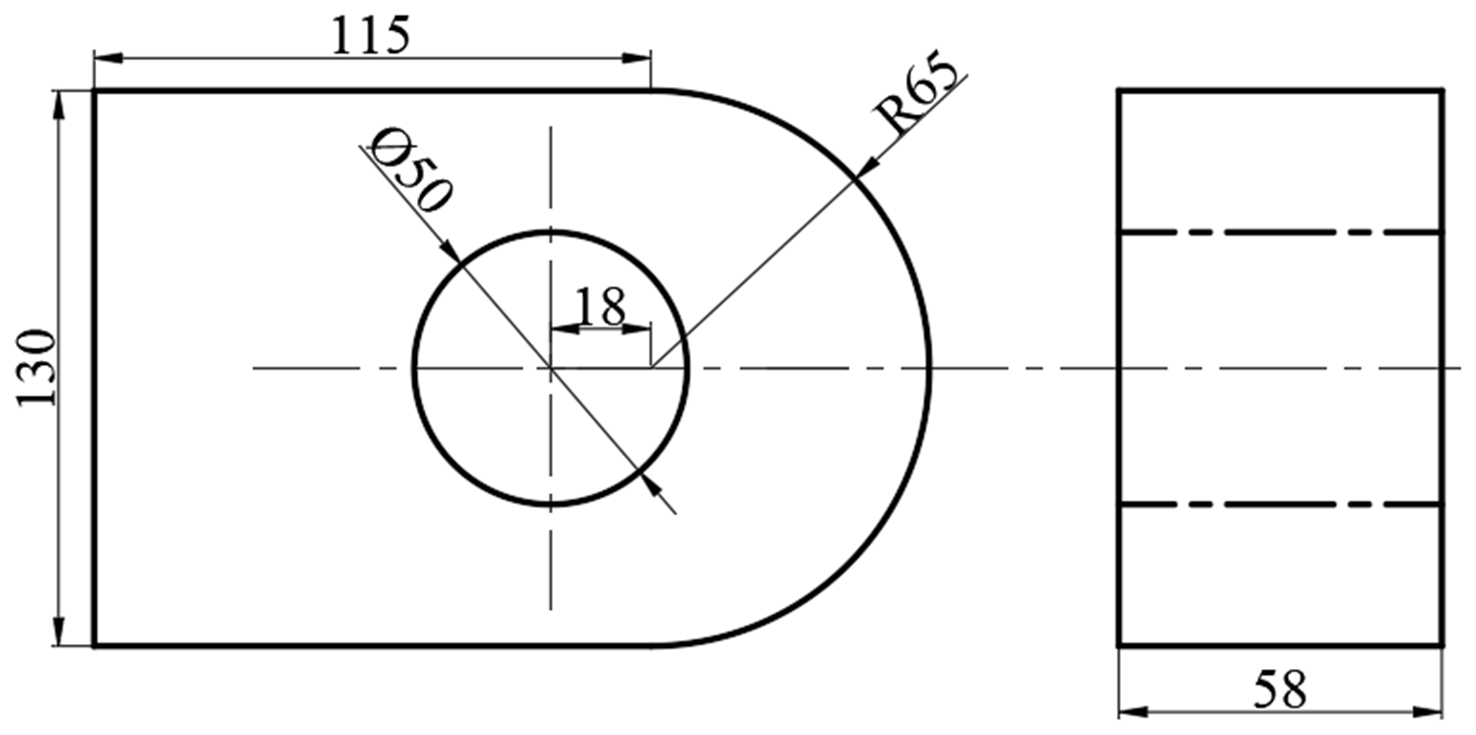
The lug-hole specimens were fabricated from 7050 high-strength aluminum alloy in the T7451 temper condition, and their chemical composition is listed in Table 1. The interference-fit sleeves were made of martensitic precipitation-hardening stainless steel 0Cr13Ni8Mo2Al, which possesses ultra-high strength, excellent impact resistance and fracture toughness, and good resistance to stress corrosion (Almeraya-Calderón et al., 2022; Afonso et al., 2023). The basic mechanical properties of the lug-hole specimens and the interference-fit sleeves at room temperature are presented in Table 2. The geometric dimensions of the lug-hole specimen are illustrated in Fig. 1, with the inner diameter of the lug hole being specified as Φ50H8 mm. The interference-fit sleeve has a length of 58 mm and an outer diameter of Φ50h8 mm, while its inner diameter is determined by the relative expansion level. Additionally, the inner wall of the sleeve is uniformly coated with a molybdenum disulfide dry-film lubricant.
2.2 Experimental methods
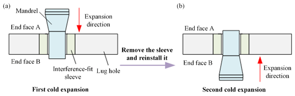
The lug-hole specimens were strengthened using the interference-fit sleeve cold-expansion process, as illustrated in Fig. 2. Specimens were fabricated from the same batch of materials and designated as 1-1#, 1-2#, 1-3#, and 1-4# for the primary cold-expansion strengthening experiments, with relative expansion levels set at 1.7 %, 2.0 %, 2.3 %, and 2.5 %, respectively. An additional set of specimens from the same material batch, designated as 2-1#, 2-2#, 2-3#, and 2-4#, was used for the reverse secondary cold-expansion strengthening experiments. For these, the primary relative expansion level was uniformly set at 1.7 %. Following primary expansion, the sleeves were removed, and reverse secondary cold-expansion was performed at relative expansion levels of 1.7 %, 2.0 %, 2.3 %, and 2.5 %, respectively.
The relative expansion level, denoted by η, is calculated as follows:
where Dt is the diameter of the working section of the expansion mandrel, Dn is the inner diameter of the interference-fit sleeve, and Dm is the initial inner diameter of the lug hole.
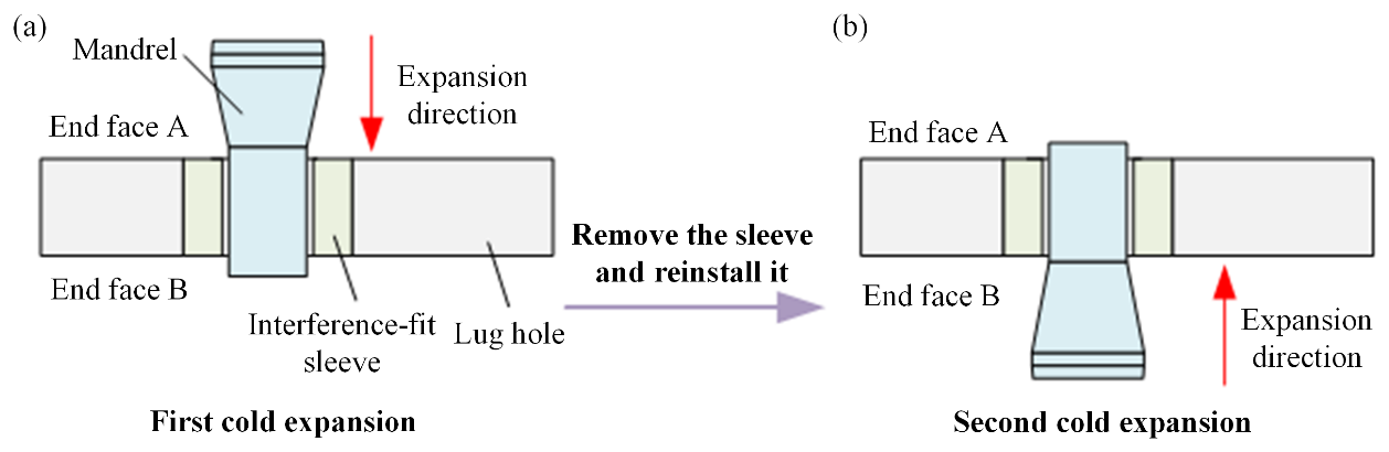
Figure 2Schematic diagram of the interference-fit sleeve secondary cold-expansion strengthening process. (a) Primary cold expansion, (b) secondary cold expansion.
The experimental equipment utilized a gas–liquid booster pump station and a dedicated puller gun. During the experimental procedure, the clearance-fit sleeve was initially positioned within the lug hole of the specimen. Then, the non-working end of the mandrel was passed through the sleeve hole and connected to the puller gun. The nose cap installed at the front end of the puller gun restricted the axial movement of the sleeve. Driven by the pump station, the puller gun enabled the mandrel to pass through the lug hole at a uniform speed. The working section of the mandrel progressively expanded the sleeve along the expansion direction until it completely exited the inner wall of the lug hole, thereby concluding the first-pass cold-expansion strengthening experiment. Subsequently, the sleeve was removed and replaced with a new sleeve of the corresponding specification to conduct the reverse secondary cold-expansion strengthening experiment. To minimize potential damage to the structural connection hole during removal, a combined method of cutting and pulling was employed to extract the original sleeve. The experimental procedure proceeded as described above. For analytical convenience, the mandrel-entry end of the first-pass cold expansion is designated as end face A, and the mandrel-exit end is designated as end face B.
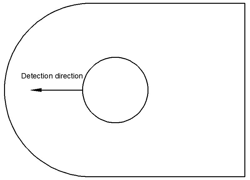
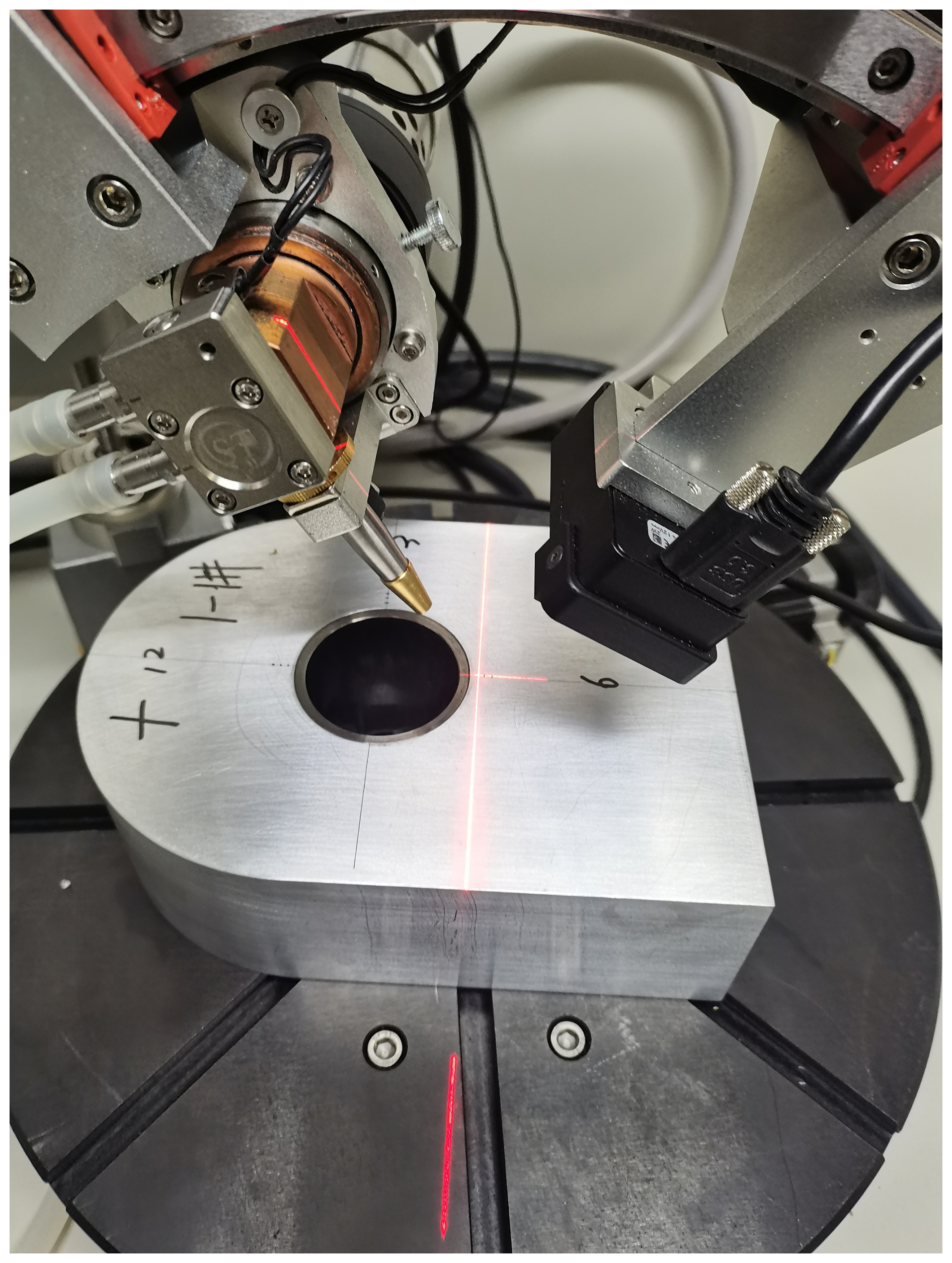
To investigate the radial residual stress distribution on the hole wall of the lug-hole specimen after the interference-fit sleeve cold-expansion strengthening process, an XL-640 X-ray diffractometer (XRD) was employed to measure the residual stress on the end faces of the lug hole. The testing conditions included a CrKα target, a (311) diffraction plane, a spot diameter of 2 mm, a tube voltage of 20 kV, and a tube current of 5 mA. The distribution of the measurement points is shown in Fig. 3, with a measurement spacing of 1 mm. In the test results, positive (“+”) values denote tensile stress, while negative (“−”) values denote compressive stress. The measurement direction was radial to the hole wall. The X-ray diffractometer is depicted in Fig. 4.
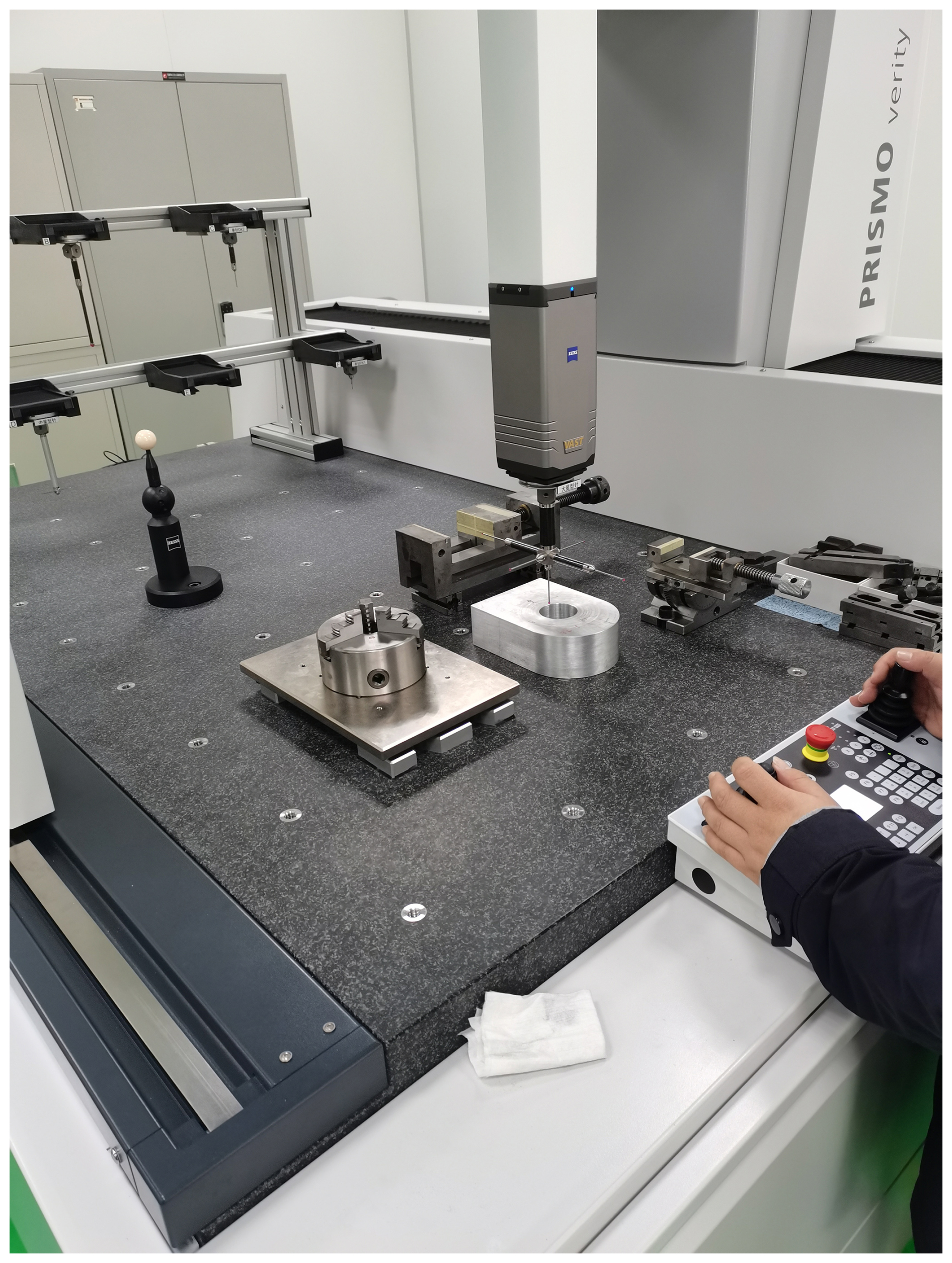
To investigate the radial plastic deformation of the specimen hole wall after interference-fit sleeve cold-expansion strengthening, the inner diameter of the specimen before and after expansion was measured using a ZEISS PRISMO coordinate measuring machine (CMM) from Germany. The measurement locations were divided into end face A and end face B, and the average of three measurements was taken for each location. The measurement accuracy of the equipment was () µm, and the resolution of the scanning probe was 0.05 µm. The hole diameter measurement process is shown in Fig. 5.
2.3 Finite-element model for cold-expansion strengthening
To study the residual stress distribution and hole deformation patterns of the lug-hole specimen strengthened by the interference-fit sleeve, a finite-element model for the interference-fit sleeve cold-expansion strengthening of the lug-hole specimen was established based on the actual strengthening process, as shown in Fig. 6.
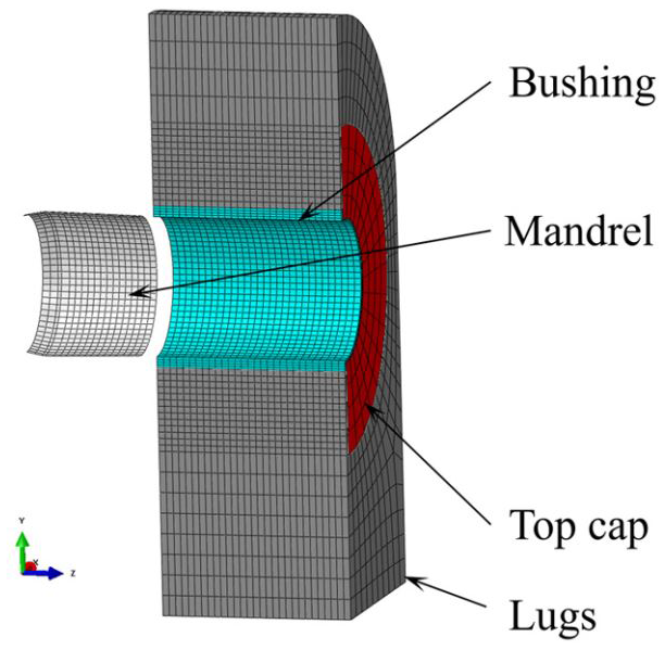
During the cold-expansion strengthening process, the mandrel slowly and uniformly expands the sleeve from the entry end to the exit end. The entire cold-expansion strengthening process can be considered to be quasi-static; thus, a general static analysis method was adopted to simulate the process. When defining the interaction relationships between the components, we consider the significant relative sliding between the mandrel and the interference-fit sleeve. According to the HB/Z 170-2005 standard, the surface roughness (Ra) of the mandrel is less than 0.4 µm, and a dry-film lubricant is applied to the inner wall of the sleeve; therefore, the tangential contact behavior is defined as finite sliding with a friction coefficient of 0.1. Because the tangential relative sliding between other contact surfaces was minimal, they were defined with small sliding to enhance computational efficiency. The normal behavior of the contact surfaces among all interaction pairs was defined as “hard” contact, meaning no interpenetration was allowed. Since the hardness and stiffness of the mandrel and the nose cap are sufficiently higher than those of the sleeve and the specimen, it was assumed that neither the nose cap nor the mandrel deformed during the entire installation process of the interference-fit sleeve. To reduce computational costs, the mandrel and the nose cap were defined as rigid bodies and meshed using shell elements.
To ensure the reliability of the simulation results, a mesh-independence verification was conducted on the finite-element model. Various mesh densities were evaluated using the maximum pulling force (Fmax) exerted on the mandrel during the cold-expansion process as the evaluation criterion. A comparison of the pulling force across different element counts (N) revealed that the force becomes insensitive to changes in element quantity at approximately 27 284 elements. Consequently, a meshing scheme comprising approximately 27 284 elements was adopted for all subsequent computational analyses.
2.4 Characterization of residual stress on fatigue performance
The influence of residual stress on the fatigue limit of materials can be expressed using the Goodman relationship (Kikuchi et al., 2023), with the specific formula as follows:
where is the fatigue limit of the material when the residual stress is σm, is the fatigue limit of the material when the residual stress is O, σm is the mean stress, m is the mean stress sensitivity factor, and σb is the tensile strength.
When a residual stress σr is generated in the specimen, it can be simplified as a component of σm. In this case, Eq. (1) can be transformed into
As can be observed from Eq. (3), the fatigue limit changes with variations in residual stress. When the residual stress is positive (tensile stress), the fatigue limit decreases; when the residual stress is negative (compressive stress), the fatigue limit increases. Therefore, the residual compressive stress layer formed by interference-fit sleeve cold-expansion strengthening can enhance the surface properties of the specimen.
The effect of residual compressive stress on delaying fatigue crack initiation can also be described using the modified Goodman (Hwang et al., 2018) formula, as shown in Eq. (4).
In the above, σa is the equivalent fatigue strength, σf is the fatigue endurance of the material under fully reversed loading, σm is the mean stress caused by external loads, σb is the ultimate tensile strength of the material, and σR is the residual compressive stress generated by cold expansion. The modified Goodman relationship indicates that, without considering microstructural effects, a linear relationship exists between the stress amplitude and the mean stress. Assuming that the stress amplitude and the mean stress σm under external loads remain constant and that the ultimate tensile strength σb of the material remains constant, the residual compressive stress σR can be treated as a static stress and, consequently, as another form of mean stress. Therefore, the equivalent fatigue strength σa increases with the increase in the residual compressive stress σR, thereby extending the crack initiation life.
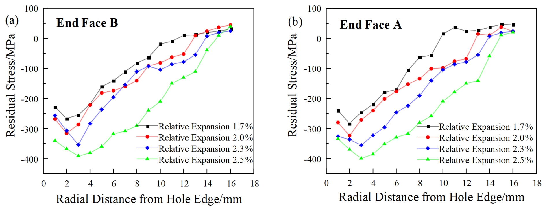
Figure 7Radial residual stress distribution on the hole wall after secondary cold expansion. (a) End face B of the lug hole. (b) End face A of the lug hole.
3.1 Effect of secondary cold-expansion strengthening on residual stress*
The radial residual stress distribution on the hole wall after the secondary cold expansion of the interference-fit sleeve is shown in Fig. 7. As can be observed from the figure, the residual stress values exhibit similar variation trends under different relative expansion levels, with both the peak residual compressive stress and the depth of the stress layer increasing as the relative expansion level increases. At a secondary relative expansion level of 1.7 %, the maximum residual compressive stress values on both end face B and end face A appear at a radial distance of approximately 2 mm from the hole wall, with a maximum of −283.7 MPa for end face B and −266.7 MPa for end face A. When the relative expansion level increases to 2.5 %, the maximum residual compressive stresses on both end faces shift to a radial distance of approximately 3 mm from the hole wall, with a maximum of −400.3 MPa for end face B and −391.6 MPa for end face A. As the expansion level increases from 1.7 % to 2.5 % during the secondary cold-expansion strengthening process, the depth of the residual compressive stress layer also extends from 9 to 14 mm.
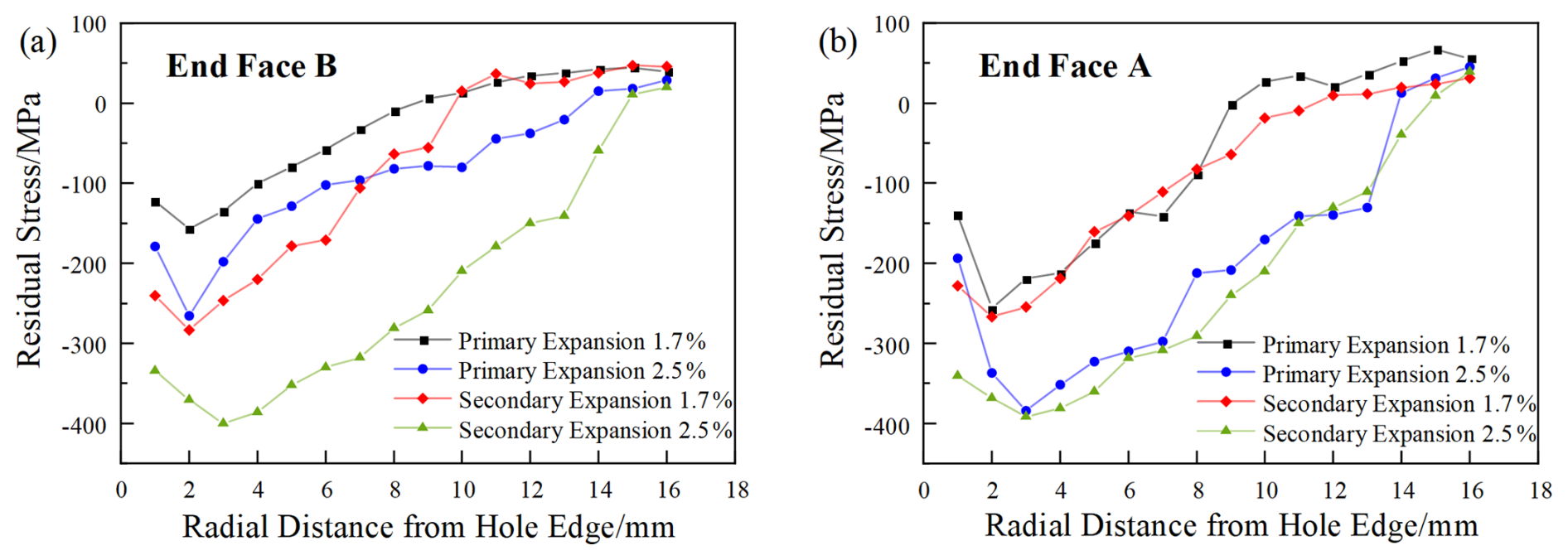
Figure 8Comparison of residual stresses in the lug hole after primary and secondary cold expansion. (a) End face B of the lug hole. (b) End face A of the lug hole.
An analysis of the cold-expansion strengthening process reveals that, as the mandrel expands axially, the material of the sleeve's inner hole undergoes plastic flow in both the axial and radial directions. This causes elastoplastic deformation around the hole wall of the lug-hole specimen, which gradually propagates radially outward as the relative expansion level increases, thereby forming a residual compressive stress layer of a certain depth radially along the hole wall. After the cold expansion is completed and the load is removed, the surface material of the lug hole inner wall undergoes springback, causing the peak residual compressive stress to appear at the subsurface of the hole wall.
A comparison of the residual stresses in the lug hole after primary and secondary cold-expansion strengthening is presented in Fig. 8. As shown in the figure, compared to the primary expansion results, the overall difference in residual compressive stress on end face B after secondary cold-expansion strengthening is marginal; however, the residual compressive stress on end face A is significantly enhanced. This is because, during the secondary cold-expansion strengthening of the interference-fit sleeve, the surface finish of the hole wall improves, and the sleeve fits more tightly into the lug hole. This leads to a redistribution of the residual compressive stress, resulting in comparable magnitudes and depths of the stress fields on end face A and end face B after secondary cold-expansion strengthening . This indicates that there is no significant difference in the strengthening effect at both ends of the hole after secondary expansion. It demonstrates that the secondary cold-expansion strengthening process significantly improves the fatigue strength of end face A, thereby effectively extending the overall fatigue life of the lug hole.
After the reverse secondary cold-expansion strengthening, the magnitude and depth of the residual stress field at end face B are comparable to those achieved after the primary cold expansion. From a materials science perspective, this is attributed to the absence of further plastic deformation in the deeper radial layers of the hole wall. Conversely, the residual compressive stress at end face A is significantly enhanced following the reverse secondary cold expansion. This occurs because end face A, which served as the entry end during the primary expansion, acts as the exit end during the secondary process. As the mandrel moves from end face B towards end face A, it forces the lug hole material to undergo renewed plastic flow in the reverse direction, both axially and radially. Under the dual constraint of the surrounding lug material and the nose cap at the front of the puller gun, a reverse reactive force is exerted on the plastically deformed surface material. This induces the formation of high-density, uniformly distributed dislocations on the hole wall surface in the end face A region, leading to atomic structural distortion. Macroscopically, this effect manifests as the generation of a high-amplitude, deep residual compressive stress layer near the surface of the hole wall. Studies have shown that high-amplitude residual compressive stress is the primary factor contributing to the enhancement of the fatigue limit and the reduction in fatigue notch sensitivity in specimens (Sapora et al., 2020; Chapetti, 2024). During service, the residual compressive stress generated by cold-expansion strengthening effectively offsets a significant portion of the externally applied loads, decreasing the mean stress acting on and around the hole edge to a certain extent. This effectively mitigates stress concentration around the hole; delays the risk of damage such as fatigue cracks caused by external loads; and, consequently, significantly improves the in-service performance of the specimen's hole structure.
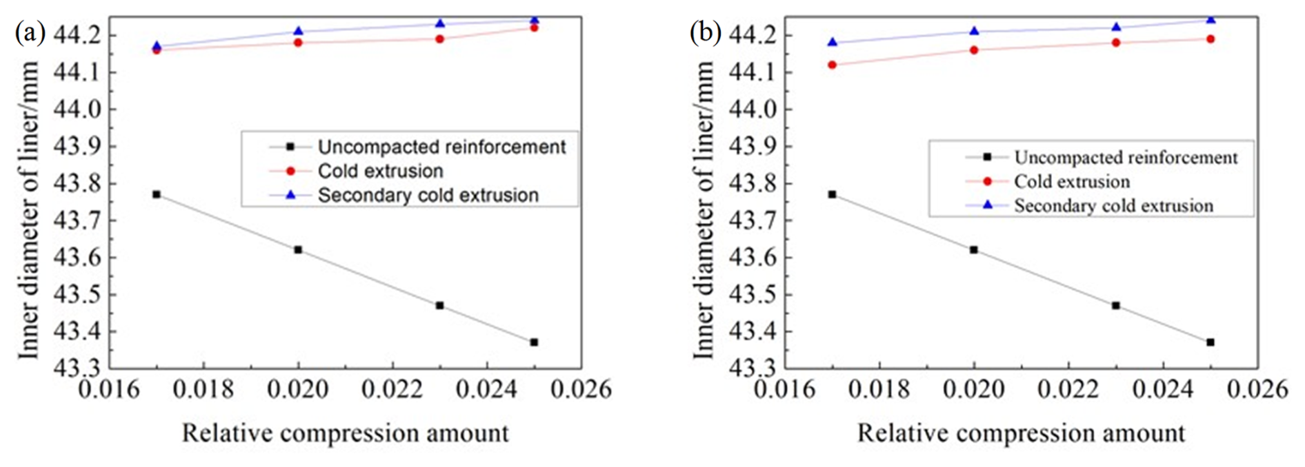
Figure 9Changes in the inner diameter of the sleeve after secondary cold expansion. (a) Inner diameter at sleeve end face A (b), inner diameter at sleeve end face B.
3.2 Analysis of plastic deformation in lug hole after cold-expansion strengthening
The changes in the inner diameter of the sleeve after secondary cold expansion are shown in Fig. 9. As depicted, the inner diameter of the sleeve increases slightly after secondary expansion compared to the primary expansion, and this increase becomes more pronounced with larger relative expansion levels. This indicates that the sleeve undergoes radial plastic deformation under the extrusion force; the greater the extrusion force, the more obvious the plastic deformation. At a relative expansion level of 1.7 %, the increments in the inner diameters of the sleeve at end face A and end face B are 0.40 and 0.41 mm, respectively. When the relative expansion level increases to 2.5 %, the increments at both end face A and end face B reach 0.87 mm.
Observing the deformation data, it is found that, compared to the primary cold-expansion strengthening experiment, the inner-diameter expansion of the sleeve is more pronounced after secondary cold expansion. However, the difference in deformation between end face A and end face B of the sleeve is narrowed further. This suggests that secondary cold-expansion strengthening effectively mitigates the uneven plastic deformation at both ends of the sleeve, ensuring a more uniform stress distribution along the thickness direction of the lug-hole specimen during the expansion process. Similarly to primary cold-expansion strengthening, the inner diameters of the sleeves strengthened under all four relative expansion levels are smaller than the 44.62 mm diameter of the mandrel's working section. This indicates that, upon completion of the secondary expansion and removal of the load pressure, the sleeve experiences elastic spring back in the radial direction.
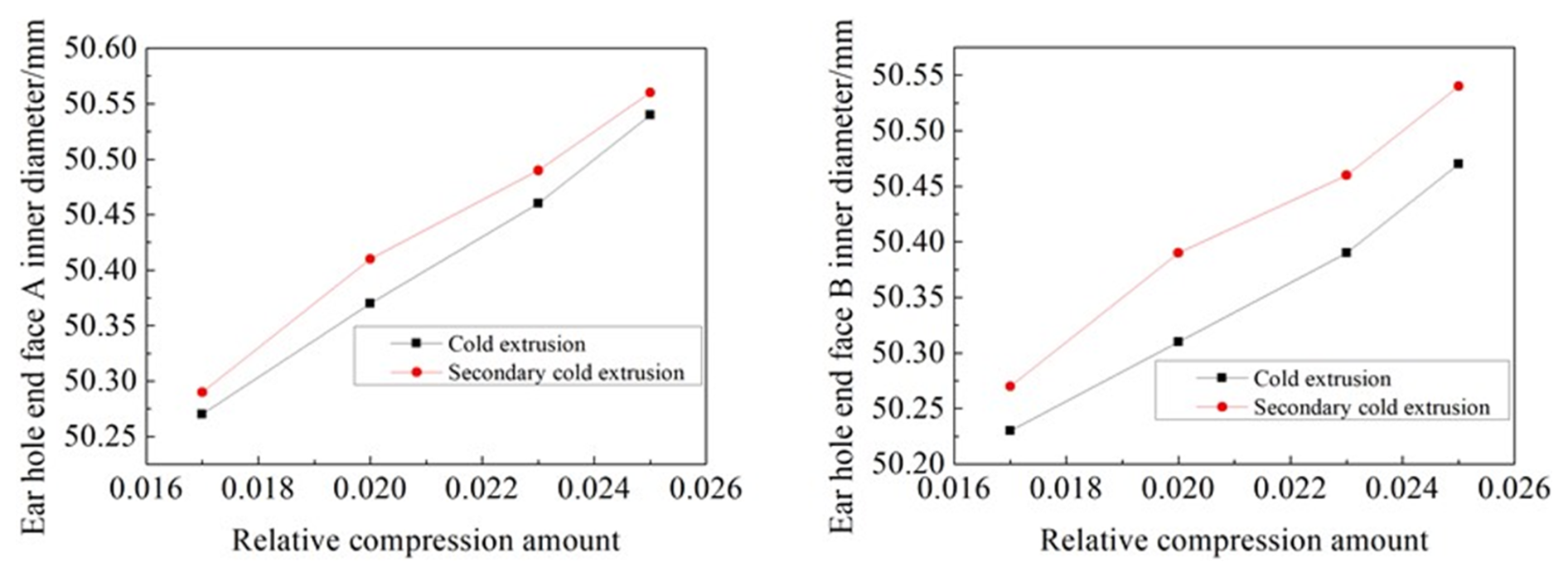
The variations in the inner diameter of the lug hole following the secondary cold expansion (SCE) of the interference-fit sleeve are illustrated in Fig. 10. As shown, under the secondary expansion action exerted by the mandrel and the sleeve, the hole diameters at both end face A and end face B of the specimen increase to varying degrees, with the magnitude of expansion becoming more pronounced as the relative expansion level increases. At a relative expansion level of 1.7 %, the inner diameters of the lug hole at end face A and end face B reach 50.29 and 50.27 mm, respectively, representing increments of 0.29 and 0.27 mm compared to the pre-expansion state. When the relative expansion level increases to 2.5 %, the inner diameters at end face A and end face B increase to 50.56 and 50.54 mm, corresponding to expansion increments of 0.56 and 0.54 mm, respectively.
Compared to primary cold expansion, the magnitude of hole diameter deformation increases slightly after secondary cold expansion. The main enhancement occurs at end face B. This is because the plastically flowing material at end face B is re-extruded during the secondary expansion process, resulting in more pronounced hole diameter variations at end face B. This ultimately ensures that the increments in hole diameter at end face B and end face A become comparable after secondary strengthening.
Studies have shown that a plastic deformation layer of a certain depth forms on the hole wall surface. During the cold-expansion strengthening process, the surface metal of the hole wall undergoes severe plastic deformation, and the closer it is to the surface, the more severe the deformation becomes (Ahadi et al., 2017). This deformation process generates a large number of dislocations within the grains; due to their interactions, these dislocations entangle to form high-density dislocation cellular structures. Following the interference-fit sleeve cold-expansion strengthening, the microstructure on the surface of the lug hole undergoes deformation due to the extrusion of the mandrel, leading to the formation of a grain-refined layer at the hole edge. This grain refinement generates a higher density of grain boundaries, which more effectively impede dislocation motion. Consequently, as a greater number of grains with diverse crystallographic orientations must coordinate during deformation, the material's resistance to plastic deformation increases, thereby manifesting a superior strengthening effect. Ultimately, this grain refinement and grain boundary sliding elevate the yield strength and hardness of the material, increase the resistance at the crack tip, effectively retard fatigue crack initiation and propagation, and comprehensively enhance the surface properties of the lug hole.
3.3 Analysis of plastic deformation on lug hole end faces after cold-expansion strengthening
By magnifying the deformation tendency of the lug with a cold-expansion strengthening level of 2.5 %, it can be observed that uneven deformation occurs on both the lug end faces and the hole wall. The deformation tendency of the lug is shown in Fig. 11.
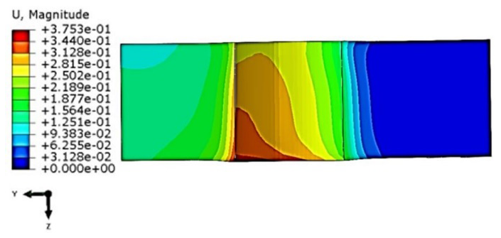
The flatness of the upper and lower end faces of the lug decreases, slight protrusions appear at both ends of the hole wall, the cylindricity of the lug hole is reduced, and the lug exhibits slight overall warping. Based on the analysis of actual working conditions, these deformation tendencies are caused by the asymmetrical forces acting on the entry end and the exit end of the lug during cold-expansion strengthening. For clarity, a scalar “deformation difference (ΔR)” is introduced to evaluate the cylindricity of the lug hole. It represents the distance from each point along path 4 (starting from the entry end) to the hole axis minus the distance from the exit end point to the hole axis. Extracting ΔR under different expansion levels, the deformation tendency of the hole wall is plotted in Fig. 12.
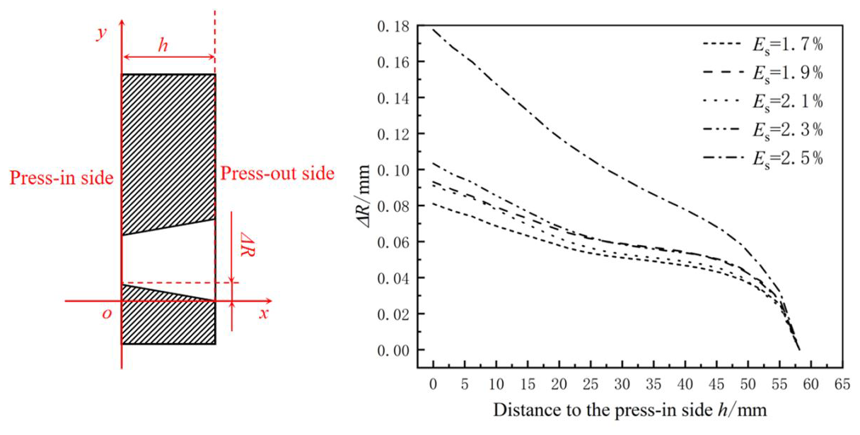
The distribution pattern of ΔR proves that the lug hole transforms from a cylindrical shape into an approximate truncated cone shape after the installation of the interference-fit sleeve. The diameter at the exit end is slightly larger than that at the entry end. Moreover, as the expansion level increases, the inclination of the lug hole wall also increases. When the hole wall is under compression, an excessive inclination can lead to a risk of stress concentration at the entry end of the hole wall. After cold-expansion strengthening, the base hole of the lug deforms due to the extrusion from the interference-fit sleeve, resulting in changes in verticality and cylindricity. However, a subsequent reaming process can ensure that indicators such as roughness, verticality, and cylindricity of the inner wall of the sleeve meet operational requirements.
3.4 Optimization of cold-expansion strengthening
After the reverse secondary cold expansion (SCE) of the lug hole, the residual compressive stress at end face A (the entry end of the primary expansion) was significantly enhanced, indicating a correlation with the effectiveness of the expansion process.
A force analysis was conducted on the installation process of the interference-fit sleeve. Micro-elements 1, 2, and 3 on the cross-section were selected as the objects of analysis; the force analysis of the thick-walled cylinder along the axial direction is shown in Fig. 13.
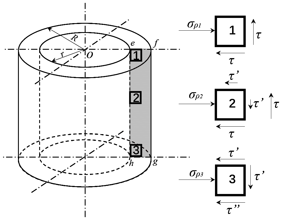
Since the upper end of micro-element 1 is a free end, it is subjected only to the shear stress provided by the unexpanded material at its lower end during expansion. Micro-element 2 is subjected to shear stresses at both its upper and lower ends. Micro-element 3 experiences shear stress from the overlying material, as well as friction-induced shear stress from the nose cap. According to equilibrium conditions, it is found that σρ1<σρ2 and σρ1<σρ3. During the cold-expansion strengthening process, the entry end of the lug hole is subjected to less force, resulting in smaller strains. This leads to lower residual stresses after expansion and causes the lug hole to adopt a truncated cone shape. During the expansion process, as the sleeve material flows towards and accumulates at the exit end, this tendency is exacerbated, leading to warping of the lug.
To restrain the warping of the lug, providing radial frictional resistance on the entry end face can effectively enhance the residual compressive stress at that end. However, due to practical operational constraints, it is often difficult to apply external loads to the entry end face of the lug hole specimen. Consequently, extending the sleeve length is proposed to address the issues of low residual stress and susceptibility to warping at the entry end.
To verify the effectiveness of the improved design method, a finite-element model was established for the lug hole specimen. The thickness of the specimen was 58 mm, and the interference-fit sleeve lengths were set to 58, 59, and 60 mm to ensure that end face A (entry end) could be completely covered by the sleeve during the cold-expansion strengthening process.
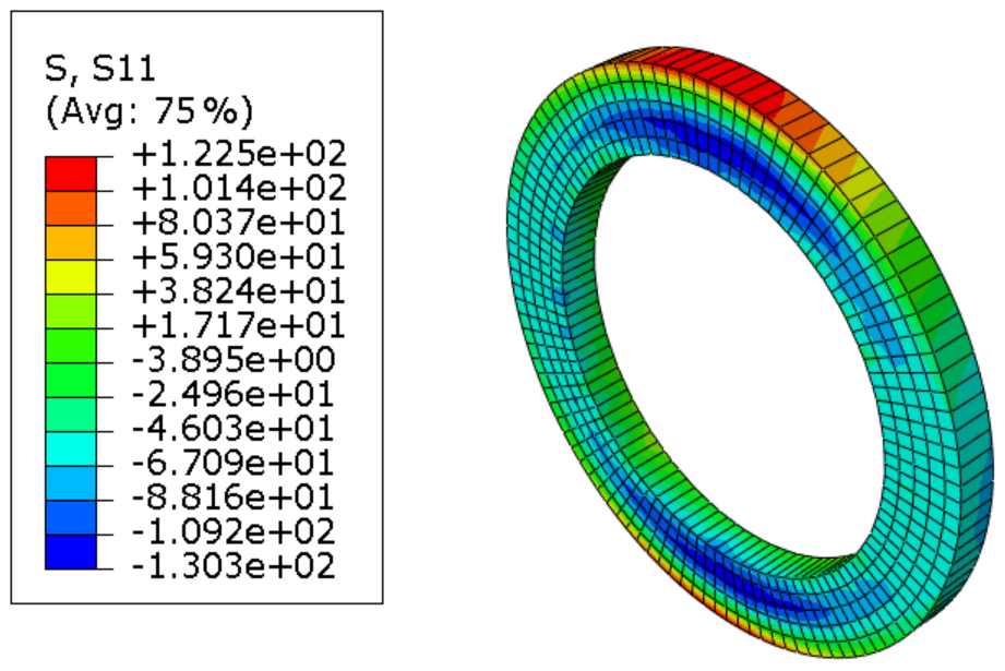
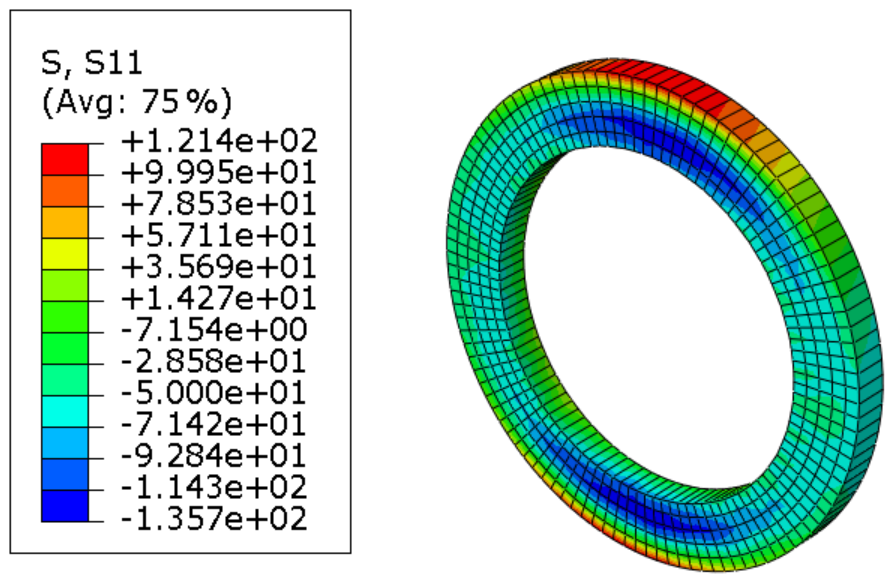
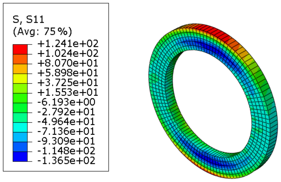
As shown in Figs. 14, 15, and 16, the analysis reveals that, with an increased sleeve length, the working section of the mandrel expands the sleeve before entering the lug hole specimen. Due to the lack of reverse constraint from the specimen, the expansion of the protruding portion of the sleeve becomes more pronounced. In addition to generating a radial load at the edge of the lug hole, the expansion of the protruding sleeve section also imparts an axial load on the hole edge. This enhances the stress at the entry end while simultaneously reducing the deformation of the lug end face.
Comparing the stress conditions at the entry end for the sleeve lengths of 58, 59, and 60 mm, it is evident that the compressive stress effect becomes more significant as the protrusion of the sleeve increases. This demonstrates that extending the sleeve length is an effective method for improving the residual compressive stress at the entry end.
In this paper, based on the primary cold-expansion strengthening of interference-fit sleeves, secondary cold-expansion strengthening experiments were conducted on 7050 aluminum alloy lug-hole specimens. The effects of varying relative expansion levels on the residual stress distribution and plastic deformation of the lug hole were investigated, along with the performance gains brought by different expansion modes and sleeve parameters. The main conclusions are as follows:
-
After both primary and secondary cold-expansion strengthening of the interference-fit sleeve, significant residual compressive stresses were generated in the vicinity of the 7050 aluminum alloy lug hole wall, forming a residual compressive stress layer of a certain depth in the radial direction. As the relative expansion level increases, both the peak residual compressive stress and the range of the stress field gradually expand. At a relative expansion level of 2.5 %, the peak residual compressive stresses after primary and secondary cold-expansion strengthening reached −384.2 and −400.3 MPa, respectively, with a residual compressive stress layer depth of approximately 14 mm.
-
After primary cold-expansion strengthening, the residual compressive stress on end face B was noticeably higher than that on end face A. However, after the secondary cold-expansion strengthening of the sleeve, the residual stress at both end faces of the lug-hole specimen became more uniform, and the residual stress on end face A was significantly improved. Simulation results also confirmed a more uniform distribution of residual stress along the thickness direction of the specimen after secondary cold-expansion strengthening .
-
Both the sleeve and the lug-hole specimen underwent plastic deformation after secondary cold-expansion strengthening, and the degree of plastic deformation increased with higher relative expansion levels. At a relative expansion level of 2.5 %, the inner diameters at end face A and end face B of the primary cold-expanded specimen increased by 0.54 and 0.47 mm, respectively. After secondary cold-expansion strengthening, the inner diameters at both ends increased by 0.56 and 0.54 mm, indicating that the plastic deformation at both ends of the specimen was relatively consistent after secondary cold-expansion strengthening.
-
Optimizing the length of the interference-fit sleeve can effectively enhance the residual compressive stress at the entry end of the lug hole.
The data supporting the findings of this study are available from the corresponding author upon reasonable request.
Rujun Liu: conceptualization, methodology, investigation, formal analysis, data curation, writing (original draft). Xiang Huang: conceptualization, supervision, methodology, writing (review and editing). Yidong Bao: investigation, validation, data curation, writing (review and editing). Hao Chen: investigation, resources, validation, writing (review and editing).
The contact author has declared that none of the authors has any competing interests.
Publisher's note: Copernicus Publications remains neutral with regard to jurisdictional claims made in the text, published maps, institutional affiliations, or any other geographical representation in this paper. The authors bear the ultimate responsibility for providing appropriate place names. Views expressed in the text are those of the authors and do not necessarily reflect the views of the publisher.
This paper was edited by Zbigniew Gronostajski and reviewed by two anonymous referees.
Achard, V., Daidie, A., Paredes, M., and Chirol, C.: Optimization of the cold expansion process for titanium holes, Adv. Eng. Mater., 19, 1500626, https://doi.org/10.1002/adem.201500626, 2017.
Afonso, F., Sohst, M., Diogo, C. M. A., Rodrigues, S. S., and Ferreira, A.: Strategies towards a more sustainable aviation: A systematic review, Prog. Aerosp. Sci., 137, 100878, https://doi.org/10.1016/j.paerosci.2022.100878, 2023.
Aglawe, K., Giri, S., Dhande, M., and Shelare, S.: Application of aluminum alloys in aviation industry: A review, in: Proceedings of the International Conference on Materials for Emerging Technologies: ICMET-2021, Phagwara, India, 18–19 February 2022, AIP Conf. Proc., 2800, 020064, AIP Publishing, https://doi.org/10.1063/5.0163002, 2023.
Ahadi, A., Matsushita, Y., Sawaguchi, T., Sun, Q. P., and Tsuchiya, K.: Origin of zero and negative thermal expansion in severely-deformed superelastic NiTi alloy, Acta Mater., 124, 79-92, https://doi.org/10.1016/j.actamat.2016.10.054, 2017.
Almeraya-Calderón, F., Samaniego-Gámez, O., Maldonado-Bandala, E., Lara-Banda, M., Estupiñan-López, F., Zambrano-Robledo, P., and García-León, R.: Corrosion behavior of passivated martensitic and semi-austenitic precipitation hardening stainless steel, Metals, 12, 1033, https://doi.org/10.3390/met12061033, 2022.
Bombardier, Y., Li, G., and Renaud, G.: Fatigue life prediction at cold expanded fastener holes with ForceMate bushings, in: ICAF 2019–Structural Integrity in the Age of Additive Manufacturing, Lecture Notes in Mechanical Engineering, edited by: Niepokolczycki, A. and Komorowski, J., Springer, Cham, 658–673, https://doi.org/10.1007/978-3-030-21503-3_53, 2019.
Chapetti, M. D.: Non-propagating cracks at the fatigue limit of notches: An analysis of notch sensitivity and size effect, Materials, 17, 4632, https://doi.org/10.3390/ma17184632, 2024.
Chen, J., Ma, Y., Chen, Y., and Li, Z.: Quasistatic tensile and fatigue performances of titanium alloy open hole structures strengthened by different cold expansion mandrel front cone angles, Fatigue Fract. Eng. M., 48, 1574–1588, https://doi.org/10.1111/ffe.14559, 2025.
Emami Geiglou, Z., and Chakherlou, T. N.: Investigating the effect of cold expansion process on the fatigue behavior of aluminum alloy 7075-T6 in double-lap shear joints, Proc. Inst. Mech. Eng. L, 233, 1645–1660, https://doi.org/10.1177/1464420718781167, 2019.
Fu, Y., Ge, E., Su, H., and Xu, J.: Cold expansion technology of connection holes in aircraft structures: A review and prospect, Chinese J. Aeronaut., 28, 961–973, https://doi.org/10.1016/j.cja.2015.05.006, 2015.
Hwang, J. H., Lee, J. H., and Bae, D. H.: Welding residual stress effect of the fatigue strength at dissimilar material weld between Alloy617 and 12Cr steel, Int. J. Mod. Phys. B, 32, 1840053, https://doi.org/10.1142/S0217979218400532, 2018.
Hui, L., Wang, H., Huang, Y., and Liu, X.: Effects of different structural parameters on the 7075-T651 aluminum alloy lug structure fatigue life, Proc. Inst. Mech. Eng. G, 236, 3304–3312, https://doi.org/10.1177/09544100221083354, 2022.
Kikuchi, S., Minamizawa, K., Arakawa, J., and Ota, M.: Combined effect of surface morphology and residual stress induced by fine particle and shot peening on the fatigue limit for carburized steels, Int. J. Fatigue, 168, 107441, https://doi.org/10.1016/j.ijfatigue.2022.107441, 2023.
Kim, H. K., Carlson, S. S., Stanfield, M. L., Paddea, S., Hosseinzadeh, F., and Bouchard, P. J.: Mitigating cutting-induced plasticity errors in the determination of residual stress at cold expanded holes using the contour method, Exp. Mech., 62, 3–18, https://doi.org/10.1007/s11340-021-00756-z, 2022.
Kumar, A. and Babu, M.: Effect of proximity hole on induced residual stresses during cold expansion of adjacent holes, Mater. Today-Proc., 5, 5709–5715, https://doi.org/10.1016/j.matpr.2017.12.165, 2018.
Lin, Z., Bai, Q., Wang, H., and Zhu, Y.: Research on the residual stress field of a compression bushing-lug plate in cold expansion strengthening, Appl. Sci., 13, 11694, https://doi.org/10.3390/app132111694, 2023.
Maximov, J. T., Duncheva, G. V., and Amudjev, I. M.: A novel method and tool which enhance the fatigue life of structural components with fastener holes, Eng. Fail. Anal., 31, 132–143, https://doi.org/10.1016/j.engfailanal.2013.01.047, 2013.
Reid, L.: Hole cold expansion the fatigue mitigation game changer of the past 50 years, Adv. Mater. Res., 891, 679–684, https://doi.org/10.4028/www.scientific.net/AMR.891-892.679, 2014.
Sapora, A., Cornetti, P., Campagnolo, A., and Meneghetti, G.: Fatigue limit: Crack and notch sensitivity by finite fracture mechanics, Theor. Appl. Fract. Mec., 105, 102407, https://doi.org/10.1016/j.tafmec.2019.102407, 2020.
Shuai, H., Youli, Z., Zhihai, C., and Jia, Z.: Effect of hole cold expansion on fatigue performance of corroded 7B04-T6 aluminium alloy, Int. J. Fatigue, 126, 210–220, https://doi.org/10.1016/j.ijfatigue.2019.05.008, 2019.
Su, R., Li, J., Liu, W., and Wang, Y.: Investigation on fatigue failure of split-sleeve cold expansion holes of 7075-T651 aluminum alloy, Mater. Today Commun., 35, 106290, https://doi.org/10.1016/j.mtcomm.2023.106290, 2023.
Tang, C. Z., Li, H. W., Li, K. S., and Wang, X. L.: Data-driven fatigue life prediction of small-deep holes in a nickel based super alloy after a cold expansion process, Int. J. Fatigue, 181, 108159, https://doi.org/10.1016/j.ijfatigue.2024.108159, 2024.
Wang, J., Lei, X., Zeng, F., and Zhang, Y.: Design of a novel cold expansion tool for deep small holes based on FEM simulations and experimental study, Int. J. Adv. Manuf. Tech., 130, 4933–4949, https://doi.org/10.1007/s00170-024-12953-w, 2024.
Wang, Y., Zhu, Y., Hou, S., and Hu, J.: Investigation on fatigue performance of cold expansion holes of 6061-T6 aluminum alloy, Int. J. Fatigue, 95, 216–228, https://doi.org/10.1016/j.ijfatigue.2016.10.030, 2017.
Warner, J., Clark, N., and Hoeppner, W.: Cold expansion effects on cracked fastener holes under constant amplitude and spectrum loading in the 2024-T351 aluminum alloy, Int. J. Fatigue, 68, 209–216, https://doi.org/10.1016/j.ijfatigue.2014.05.002, 2014.
Wen, S. Z., Liu, C. Y., Wu, R. L., and Ma, C. L.: Effect of cold expansion on high cycle fatigue of 7A85 aluminum alloy straight lugs, Rare Metal Mat. Eng., 44, 2358–2362, https://doi.org/10.1016/S1875-5372(16)30020-0, 2015.
Yan, W., Wang, Y., Liang, S., and Liu, Z.: Study on the residual stress distribution of bi-directional cold expansion process performed on open holes, J. Press. Vess.-T. ASME, 145, 041501, https://doi.org/10.1115/1.4062179, 2023.
Ye, J., Quan, G., Kyvelou, P., Teh, L., and Gardner, L.: A practical numerical model for thin-walled steel connections and built-up members, Structures, 38, 753–764, https://doi.org/10.1016/j.istruc.2022.02.028, 2022.
Yuan, X., Yue, Z. F., Wen, S. F., and Zhang, L.: Numerical and experimental investigation of the cold expansion process with split sleeve in titanium alloy TC4, Int. J. Fatigue, 77, 78–85, https://doi.org/10.1016/j.ijfatigue.2015.03.014, 2015.
Zhang, Y., Wang, B., Ning, Y., Xue, H., and Lei, X.: Study on health monitoring and fatigue life prediction of aircraft structures, Materials, 15, 8606, https://doi.org/10.3390/ma15238606, 2022.