the Creative Commons Attribution 4.0 License.
the Creative Commons Attribution 4.0 License.
 | 05 Nov 2026
Quasi-static and dynamic characteristics analysis of a marine gear system under coupling misalignment
Jingyi Gong

Kaiyang Chen
Ruikai Dai
Haipeng An
Guanghao Dai
Bing Yuan
Diaphragm couplings are critical in marine gear trains but inevitably suffer from both parallel and angular misalignment, which degrade tooth-mesh conditions and excite low-frequency vibrations. This paper presents a quasi-static contact analysis model for gear systems that accounts for coupling misalignment using a coupled iterative calculation framework that integrates the misalignment mechanics model, the sliced static model, and the loaded tooth contact analysis (LTCA) model. The study analyzes the impact of coupling misalignment on the contact characteristics of the gear pair under non-ideal mesh conditions and establishes the differential equation of motion for the marine gear system. Findings reveal that coupling misalignment significantly affects mesh stiffness, which fluctuates at the misalignment frequency (twice the shaft frequency). As the imposed misalignment increases, the differences in meshing misalignment and load distribution between the left- and right-hand teeth of the double-helical gear pair increase progressively. At light loads, the quasi-static contact characteristics are more susceptible to coupling misalignment, resulting in regions of contact loss on the tooth surfaces. Coupling-misalignment excitation also induces system resonance. As misalignment and load torque increase, system vibration intensifies, with load torque primarily influencing vibration responses to mesh frequency excitation. These insights deepen the understanding of marine transmission systems and inform strategies for addressing misalignment-induced vibrations, which can enhance the performance, reliability, and longevity of marine gear systems in practical applications.
- Article
(12979 KB) - Full-text XML
- BibTeX
- EndNote


Available failure data associate rotor misalignment with over 60 % of faults in rotating equipment (Moghe and Mahure, 2017). Tests have shown that misalignment increases the vibration amplitude of the gearbox by 20 % to 40 %, leading to bearing damage (Kumar and Hirani, 2021). Diaphragm couplings are widely used in marine gear systems because they can accommodate a certain degree of misalignment. However, due to deviations in base height, coupling assembly errors, hull deformation, and other factors, couplings inevitably experience parallel and angular misalignment. Forces and moments induced by coupling misalignment compromise gear system stability. These forces and moments cause shaft deformation, gear pair disengagement, system vibration, and bearing wear. Accordingly, the effects of coupling misalignment on the quasi-static contact behavior and dynamic characteristics of marine gear systems should be systematically examined.
Most marine gear systems comprise multiple series-connected gearboxes, resulting in multiple sources of mesh excitation and coupling misalignment between the gearboxes. Dynamic interactions among the gearboxes induce system-wide coupled vibration. Changes in transmission chain flexibility under different operating conditions induce variations in mesh excitation, thereby giving rise to highly complex vibration characteristics of the system. Gong et al. (2021) proposed a hierarchical dynamic modeling approach based on a whole-system-first, substructure-second strategy. Meng et al. (2014) established a transient dynamic model of the mode-switching process for the fuel-combined-power cross-connect gearbox (CCG) using ADAMS and Simulink. Chen et al. (2022) developed a computational method for determining the clutch impact load during rapid CCG paralleling. Research to date has centered on the enhancement of operational smoothness and energy efficiency and the formulation of control schemes for transitions between operating modes.
Coupling misalignment is classified as parallel, angular, or combined misalignment. Coupling misalignment produces angular deflection and deformation. As the shaft system rotates, coupling misalignment generates time-varying forces. Coupling-misalignment modeling approaches include the mechanical method (Wang and Jiang, 2018), the equivalent shaft segment method (Hujare and Karnik, 2018), and the Lagrangian energy method (Al-Hussain and Redmond, 2002). The mechanical method uses the coupling geometry to establish the force–deformation relationship and to derive the forces induced by coupling misalignment. Gibbons (1976) derived expressions for coupling forces and moments induced by parallel misalignment under static loading conditions. Sekhar and Prabhu (1995) subsequently refined Gibbons' model by incorporating harmonic terms representing the forces and moments induced by coupling misalignment into the dynamic formulation. Xu and Marangoni (1994) derived an expression for the moment induced by angular misalignment using the kinematic theory of a Hooke joint. Xia et al. (2019) derived expressions for the forces and moments induced by parallel and angular misalignment of hexagonal flexible couplings based on deformation at the bolt locations. In the equivalent shaft segment method, also termed the finite-element method, the coupling is replaced by a shaft segment of equivalent bending stiffness. Lee and Lee (1999) and Pennacchi et al. (2012) modeled coupling misalignments in axially misaligned beam elements, with parallel and angular misalignments expressed in terms of rotational displacement vectors at the coupling nodes. The Lagrangian energy method uses Lagrange's equations and coordinate transformations to establish the system energy equation and differential equation of motion directly. This method avoids the complicated force analysis of the coupling. Al-Hussain (2003) derived an expression for the potential energy associated with angular misalignment in the flexible coupling. Zhen et al. (2020) established a dynamic model for parallel and angular misalignment subject to rotor integrity constraints. Li et al. (2017) considered the displacement constraints of adjacent rotors and the geometric relationships governing their motion to derive the kinetic and potential energy equations of a misaligned coupling-rotor system.
Research on coupling misalignment has mainly focused on rotor-bearing-coupling systems. The stability (Li and He, 2010; Huang et al., 2011), nonlinear vibration characteristics (Wu et al., 2020; Fu et al., 2022), and friction problems (Jin et al., 2021) of rotor systems under misalignment of couplings have been extensively studied in rotor dynamics. Patel and Darpe (2009a, b), Prabhakar et al. (2002), and Lu et al. (2021) found, by theoretical and experimental methods, that coupling misalignment causes a strong component at twice the shaft frequency in the rotor system vibration response. Lee and Lee (1999) confirmed through simulations and experiments that the shaft center orbit becomes elliptical under coupling misalignment, which is a typical characteristic of coupling misalignment. Wang et al. (2022b) indicated that misalignment raises the critical speed of the system and intensifies its axial vibration. Wu et al. (2020) found through simulation that the dynamic misalignment of the coupling is affected by external excitations. When other external excitations weaken the dynamic misalignment force/moment, the rotor system vibration response is linear. Wan et al. (2012) and Zhen et al. (2020) examined the stability of a multi-span rotor system supported by sliding bearings under diaphragm-coupling misalignment. Their results indicated that coupling misalignment progressively destabilizes the sliding bearings as the rotor speed increases. A limited number of studies have examined coupling misalignment in gear systems. Kumar and Hirani (2021) conducted experiments to study the impact of misalignment on gearboxes and found that misalignment can cause severe damage to bearings and uneven loading on the tooth surfaces. Wang et al. (2022a) and Xu et al. (2015) incorporated coupling-misalignment excitation into gear system dynamic models. They studied the vibration response under misalignment faults but did not account for the effects of forces and moments induced by misalignment on the meshing excitation of the gear pair. Coupling misalignment causes shaft misalignment and gear mesh misalignment. Yang et al. (2022) studied the changes in gear mesh stiffness under shaft misalignment based on an improved loaded tooth contact analysis (LTCA) model. Wang et al. (2021) proposed a gear pair mesh stiffness model incorporating inter-slice coupling and examined the influence of mesh misalignment on the resulting stiffness.
Further investigations have examined the effects of misalignment on bearing support characteristics, nonlinear contact behavior, load distribution, and more complex rotor dynamic responses. Bearing and coupling misalignment can alter vibration amplitudes and frequency components, system stability, shaft center trajectories, nonlinear contact behavior, and load distribution (Ma et al., 2015; Xu et al., 2022, 2024; Guan et al., 2025; Zhou et al., 2025; Nan et al., 2024; Ma et al., 2025; Jiang et al., 2025). These studies have provided valuable insights into the dynamic mechanisms associated with misalignment excitation and its interaction with bearing support, rub impact, and coupling contact. In gear transmission systems, installation errors have also been found to interact with structural faults and further amplify their effects on the system's dynamic response (Huang et al., 2025). However, most existing studies have focused primarily on the overall vibration response of rotor-bearing or coupling systems, while the mechanism by which coupling-misalignment excitation affects gear mesh misalignment, tooth surface contact states, and the system's dynamic response has received comparatively limited attention. In particular, the coupled effects of coupling misalignment on the left- and right-hand tooth surfaces of herringbone gears and the resulting redistribution of mesh misalignment and contact loads remain insufficiently investigated.
To address this limitation, the influence of coupling misalignment on both the system vibration response and the actual meshing state of the gear pair should be considered simultaneously. For marine gear systems, the contact characteristics of the gear pair under coupling misalignment can be analyzed, and the resulting gear pair meshing excitation, together with the excitation induced by coupling misalignment, can then be incorporated into the dynamic model to improve the accuracy of system vibration–response predictions. The method proposed in this study is primarily applicable to multistage parallel gear transmission systems. The modeling procedure is relatively straightforward and is suitable for various types of cylindrical gears, including spur, helical, and herringbone gears.
This paper investigates the transmission chain of a marine multi-engine, multi-shaft gear system. A mechanical model for parallel and angular misalignment of the diaphragm coupling is established based on geometric deformation relationships. A sliced static model incorporating misalignment forces and moments is coupled with the loaded tooth contact analysis method to analyze the quasi-static contact characteristics of gear pairs under coupling misalignment. The dynamic characteristics of the system under mixed excitation are investigated by considering coupling-misalignment excitation and gear mesh excitation simultaneously. The effects of coupling misalignment and load torque on the quasi-static and dynamic characteristics of the gear system are analyzed.
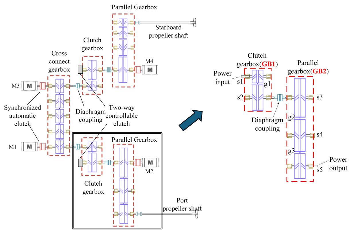
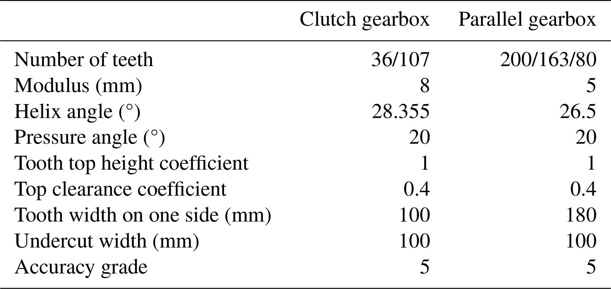
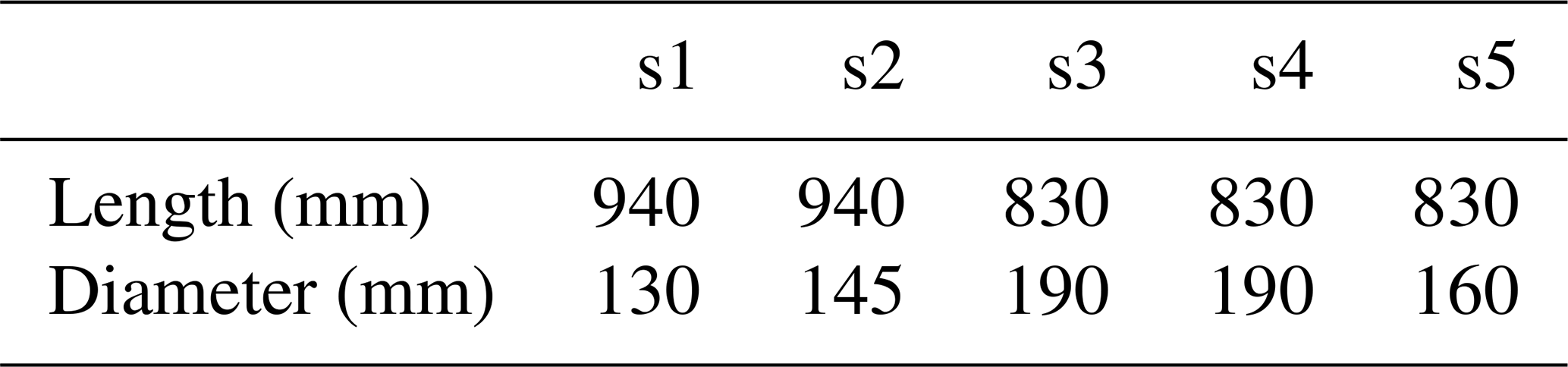
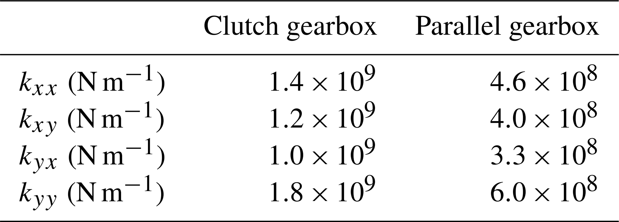
Figure 1 shows the structural schematic of the marine multi-engine multi-shaft gear system, in which the engines drive the propeller shafts individually or jointly through clutch engagement and disengagement. To facilitate the study, the transmission chain comprising the M1 engine, clutch gearbox, and parallel gearbox is selected for analysis. The effect of coupling misalignment between the two gearboxes on the gear mesh state and system vibration characteristics is analyzed. The gear parameters for each gearbox are listed in Table 1. Each pair of double-helical gears has a face width on each side greater than 10 times the modulus and is therefore classified as a wide-faced gear pair. Tables 2 to 4 show the shaft parameters, bearing support stiffness, and diaphragm coupling stiffness, respectively. The gear shafts are supported by sliding bearings arranged symmetrically about the gear pair. The stiffness and damping coefficients of the journal bearings are calculated based on classical hydrodynamic lubrication theory. The theoretical formulations of the direct and cross-coupled stiffness and damping coefficients have been systematically derived by Gong et al. (2025). Therefore, only the resulting bearing dynamic coefficients are employed in the present model, and the general derivation is not repeated here.

3.1 Mechanical model of coupling misalignment
Following the method presented by Xia et al. (2019), a misalignment model of the diaphragm coupling is established, with the left and right coupling halves used to define the coordinate system for parallel misalignment, as shown in Fig. 2. Coupling misalignment is defined as the relative offset between the left and right coupling halves. The right half of the coupling is used as the reference in the coordinate system, and it is assumed that the left half of the coupling undergoes parallel misalignment. Trigonometric functions are used to calculate the deformation at bolt holes A, B, and C in the left coupling half along each direction. These deformations are multiplied by the corresponding directional diaphragm stiffnesses to obtain the coupling force induced by parallel misalignment. The centers of the left- and right-hand coupling sections are located at points O and O′, respectively, and the angle between the y axis and the OO′ line is β. For the left coupling half, ϵx and ϵy represent the misalignments along the x and y axes, respectively. R denotes the distance from the rotor axis to the center of the bolt hole, and θ represents the angular position of bolt hole A about the coupling center O′. The relationship between β and the parallel offsets ϵx and ϵy is , and the eccentricity is OO.
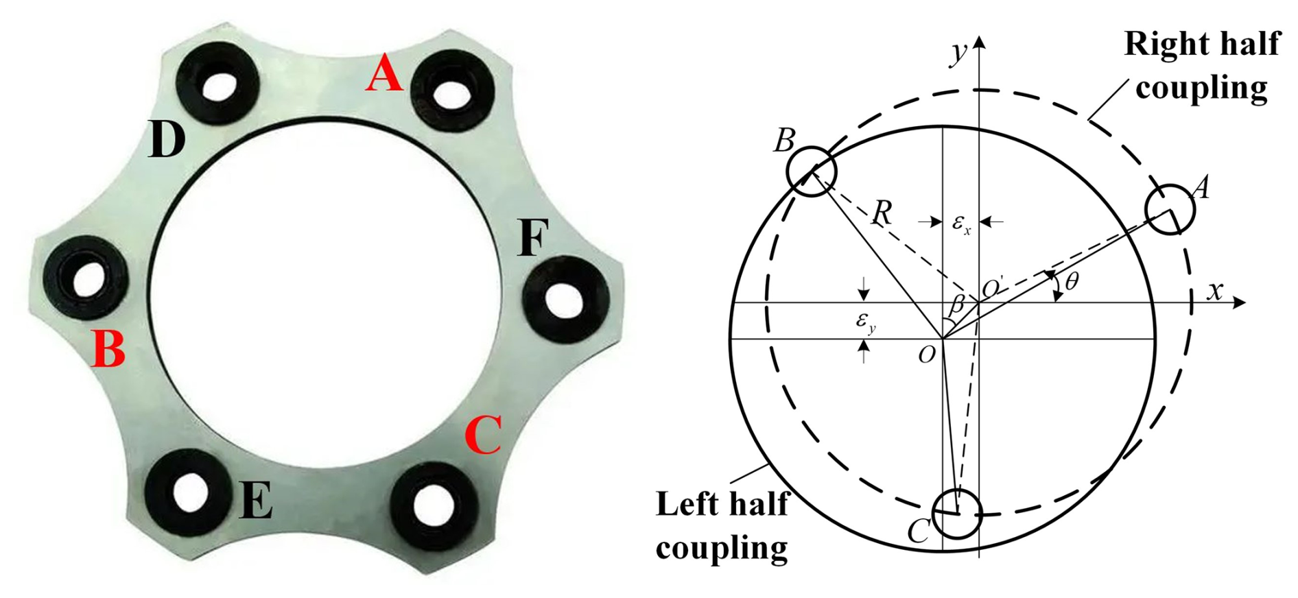
According to the law of cosines, the deformations at bolt holes A, B, and C can be obtained as
The deformation components along the x and y axes are
The x- and y-direction components of the coupling force induced by misalignment are then given by Eqs. (6) and (7), respectively, where kD is the diaphragm coupling stiffness, and μx and μy are the deformation components along the x and y axes.
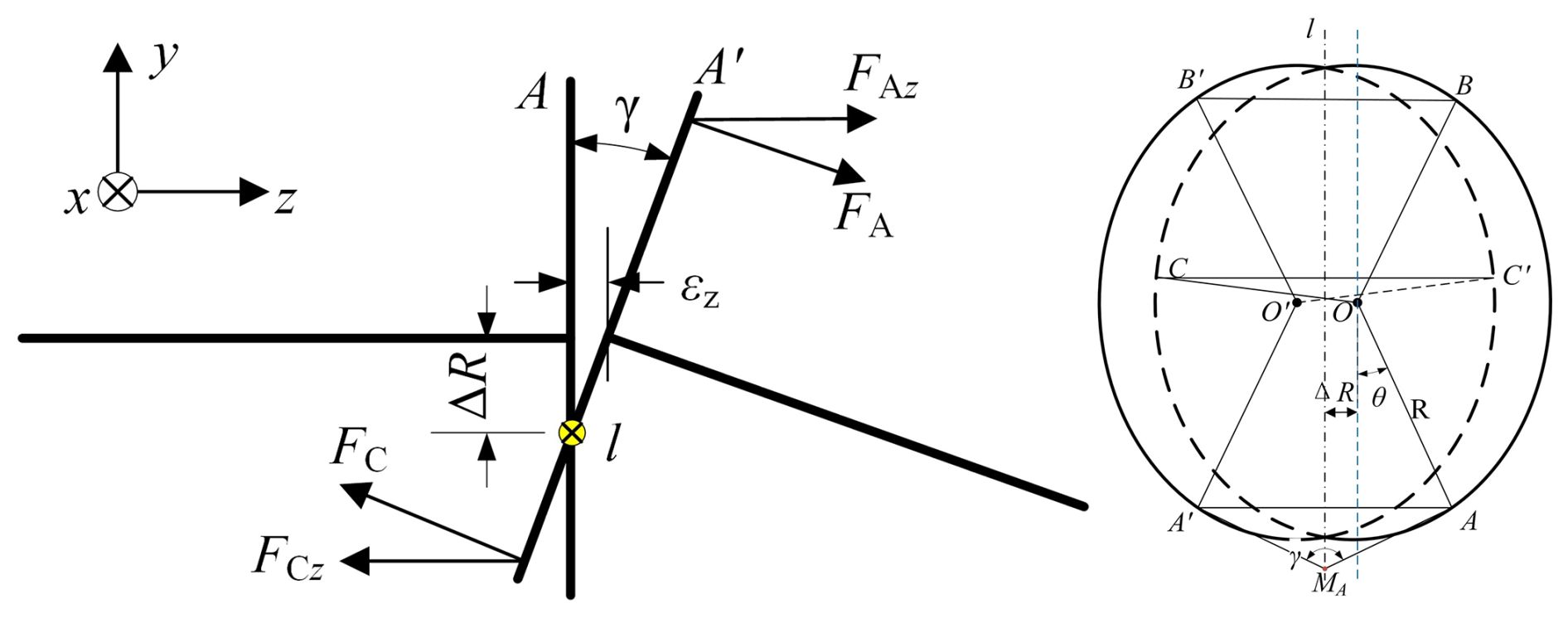
Parallel coupling misalignment is a planar mechanical problem, whereas angular coupling misalignment is a three-dimensional mechanical problem. Angular misalignment generates forces in the xy-plane, an axial force along the shaft axis, and bending moments about the x and y axes. As illustrated in the angular-misalignment schematic in Fig. 3, the left coupling half is fastened to the diaphragm by bolts passing through holes A, B, and C. γ is the offset angle. When one coupling half is angularly offset, the centers of the left and right coupling halves are separated by an axial distance ϵz, and the planes of the two halves intersect along a line l. The distance ΔR between this intersection line and the coupling center is calculated from ϵz and the offset angle γ using Eq. (8).
The deformations of the diaphragm at bolt holes A, B, and C are
The misalignment forces at each bolt hole are given by , , and , where ks is the diaphragm bending stiffness. The misalignment forces at each bolt hole are resolved along the axes of the three-dimensional coordinate system to obtain the components FAx, FBx, FCx, FAy, FBy, FCy FAz, FBz, and FCz. Summing the forces along each axis gives the resultant force induced by angular misalignment, as shown in Eq. (12). Since the torque T on the left coupling half acts along its axis, it must be resolved into components for the angularly offset right coupling half. The x- and y-direction moment components, Tx and Ty, are given in Eq. (13).
3.2 Sliced static model and mesh misalignment
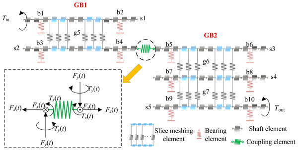
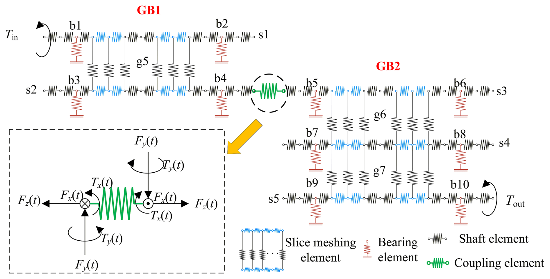
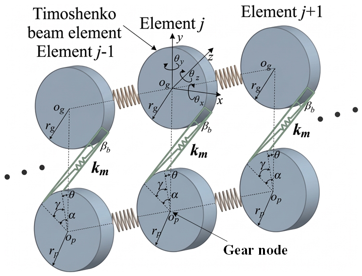
Within the framework of generalized finite-element theory, the system is represented by sliced mesh, bearing, shaft, and coupling elements, thereby forming the sliced static model illustrated in Fig. 4. At each meshing position, the mesh stiffness Km is obtained by iteratively solving the static equilibrium equations and the loaded tooth contact analysis model, with mesh misalignment calculated from the gear nodal displacements. The sliced coupling stiffness Kslice is simulated using Timoshenko beam stiffness. The method proposed by Gong et al. (2022b) is utilized to obtain the bearing element stiffness matrix Kb and the shaft and coupling element stiffness matrices Ks and Kc, respectively, followed by assembly of the element matrices. Section 3.1 shows that the coupling-misalignment forces and moments are equal in magnitude and opposite in direction for the left and right coupling halves. Therefore, the misalignment force/moment is applied to the respective nodes on either side of the coupling element in the static formulation. The equilibrium relation governing the sliced model is formulated in matrix form in Eq. (14), where P0 is the load column vector. The right-hand-side term ) represents the misalignment-induced force/moment column vector of the coupling, which is related to the offset, offset angle, and rotation angle. The explicit expression for the misalignment force/moment column vector is shown in Eq. (15). For each paired nodal degree of freedom, the two coupling nodes carry oppositely directed forces and moments.
Each gear sub-slice is represented by a two-node element with 12 degrees of freedom. The generalized coordinates of the jth slice are defined as . As shown in Fig. 5, Op and Og are the rotation centers of the driving and driven gears, βb is the base helix angle, denotes the coordinate system projection parameters, the symbol “∓” indicates the direction of rotation of the gear, α is the pressure angle, θp is the installation phase angle, and rp and rg are the base circle radii of the driving and driven gears. The driving and driven gears are connected through the slice mesh stiffness , and j is the number of slices. The slices are connected through Timoshenko beam elements. The static equations of the jth gear pair slice are given in Eq. (16), where and are the displacement and error along the line of action of the jth sliced mesh element. and denote the values of isotropic coupling stiffness between the slices. The matrix form of the static equilibrium equation of the sliced mesh element is shown in Eq. (17). The stiffness and displacement in the equations are related to the gear mesh position. When the relative displacement of a gear slice along the line of action is negative, the slice is out of contact. In the static equilibrium equation, the mesh stiffness of the corresponding slice should be set to zero. Based on the definition and calculation principles of mesh misalignment specified in clause 7.5.3.4 of ISO 6336-1:2019, the mesh misalignment formulation is further derived and extended according to the structural characteristics of the proposed model, as given in Eq. (18).
3.3 Loaded tooth contact analysis model (LTCA model)
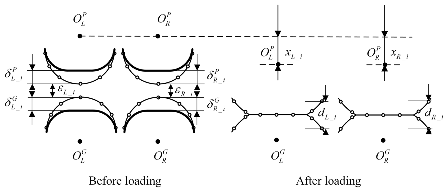
The deformation compatibility relationship before and after loading of the double-helical gear pair is shown in Fig. 6. The contact equations under load are established using the deformation compatibility relationship, as shown in Eq. (19), where δL_i and δR_i are the deformations at the ith contact point after loading, including macroscopic deformation and contact deformation. xL_i and xR_i are the rigid-body approaches, and dL_i and dR_i are the residual clearances after the contact point is loaded and deformed. ϵL_i and ϵR_i represent the initial gaps associated with the contact points, and the initial clearance is caused by the mesh misalignment of the double-helical gear pair due to the system deformation.
The total deformation is partitioned into macroscopic and contact components. Equation (20) gives the loaded contact relationship at each meshing position. The macroscopic deformation compliance matrix of the contact points along the meshing line is denoted by λ. ucontact denotes the contact deformation vector for points along the meshing line. xSTE represents the rigid-body approach vector, equivalent to the static transmission error. d is defined as the residual clearance vector at the contact points. ϵ refers to the initial clearance vector at the contact point. F represents the column vector of loads acting at the contact points, and P is the total load on the contact area. The slice mesh stiffness is obtained by summing the stiffnesses of the contact points within the corresponding gear slice.
In the loaded tooth contact analysis of a gear pair, the initial clearance at the contact point originates from the geometric errors of the gears and their assembly. Minor profile and lead deviations, installation tolerances of bearings and housings, and even bearing internal clearance can cause a discrepancy between the actual and theoretical meshing locations of the two gears, thereby forming an initial backlash when unloaded or lightly loaded. During operation, thermal expansion and shaft elastic deformation can further change the magnitude and distribution of this clearance. Because this study examines how coupling misalignment affects the contact and dynamic behavior of the gear system, the contact point clearance is attributed to the gear–mesh misalignment caused by shaft deformation induced by coupling misalignment. In Eq. (20), the contact point clearance is determined by the gear meshing misalignment through Eq. (21). Here, j denotes the number of contact points.
3.4 Iterative calculation process
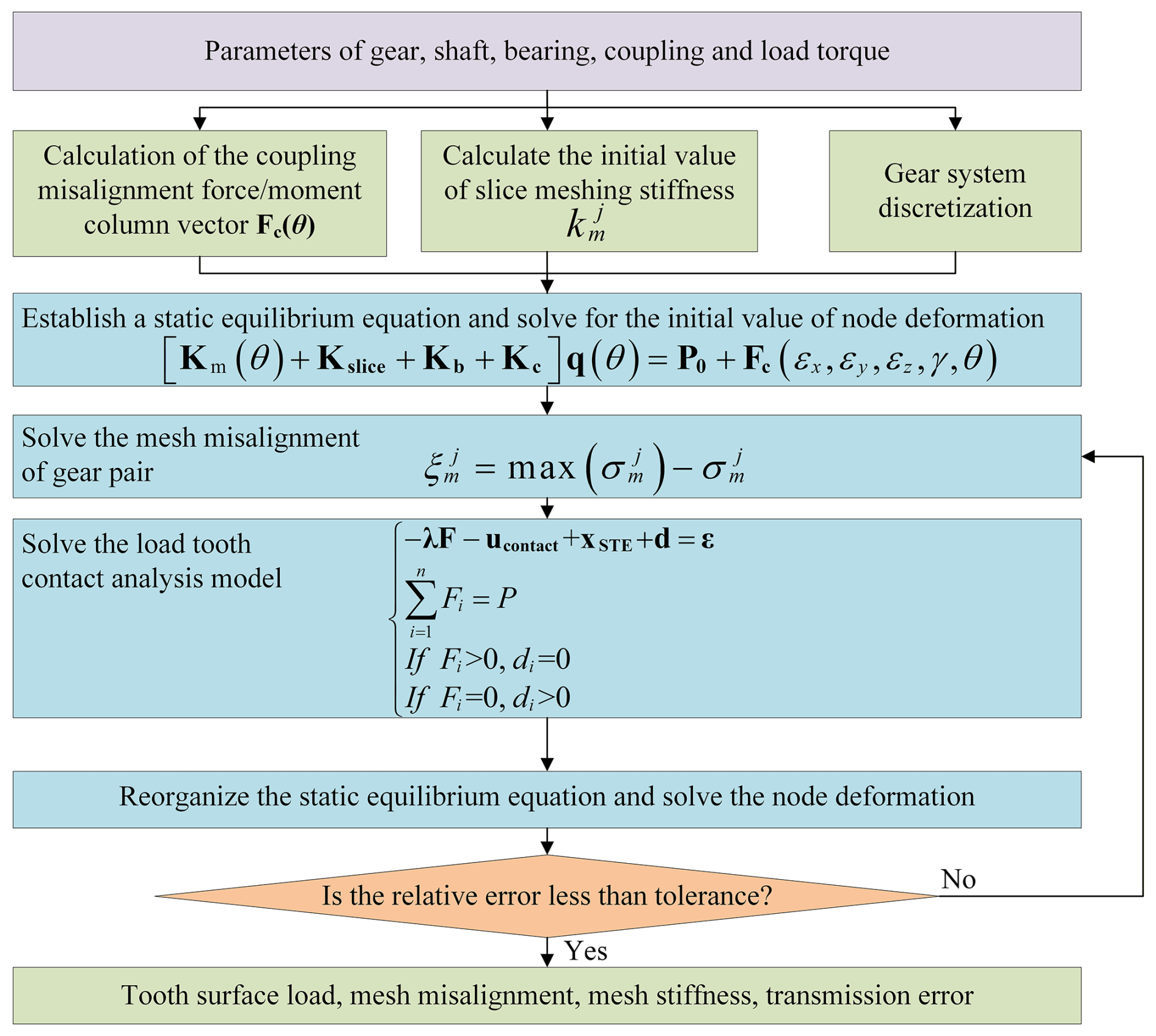
To analyze the quasi-static contact characteristics of gear pairs considering coupling misalignment, an iterative procedure is established to solve the static equilibrium equation and LTCA model and to update the mesh misalignment, as shown in Fig. 8. The corresponding steps are outlined below:
-
Discretize the gear system. Obtain the misalignment force vector from the coupling-misalignment model. Use the LTCA model to calculate the initial mesh stiffness of the sliced mesh elements.
-
Establish the static equilibrium equations for the gear system and solve them to obtain the initial deformation values of the gear nodes.
-
Determine the gear pair mesh misalignment from the nodal deformations.
-
Assign the misalignment-induced initial clearances to the contact points and solve the LTCA model to obtain the stiffness of each corresponding sliced mesh element.
-
Update the static equilibrium equation and solve for the nodal deformations.
-
Determine whether the relative error between the nodal deformations obtained in successive iterations is less than the convergence tolerance. Failure to satisfy the prescribed criterion redirects the solution procedure to step 3 for another update cycle; once the iterative sequence converges, the resulting mesh stiffness, static transmission error, tooth surface load distribution, and mesh misalignment are retained as the final outputs.
The model was experimentally verified with a test rig specifically designed to investigate the dynamic characteristics of a double-helical gearbox under various loading conditions. The setup, as detailed by Gong et al. (2022a), incorporates a purpose-built, isolation-mounted, power-circulating double-helical gear test rig, which allows for precise measurement of vibration acceleration and torque under controlled conditions. The experimental results, which focus on vibration response, torque effects, and resonance frequencies, closely match the model's predicted behavior. This agreement between the experimental and numerical results supports the capability of the adopted model to reproduce the overall dynamic behavior of the gear transmission system, providing a solid foundation for future gear system analysis and design. It should be noted that the previous experimental validation focused mainly on the overall dynamic response of the basic gear transmission model, while the coupling-misalignment-related effects introduced in the present study are investigated on the basis of this validated modeling framework, with corresponding experimental investigations to be conducted in subsequent work.
4.1 Effect of coupling misalignment
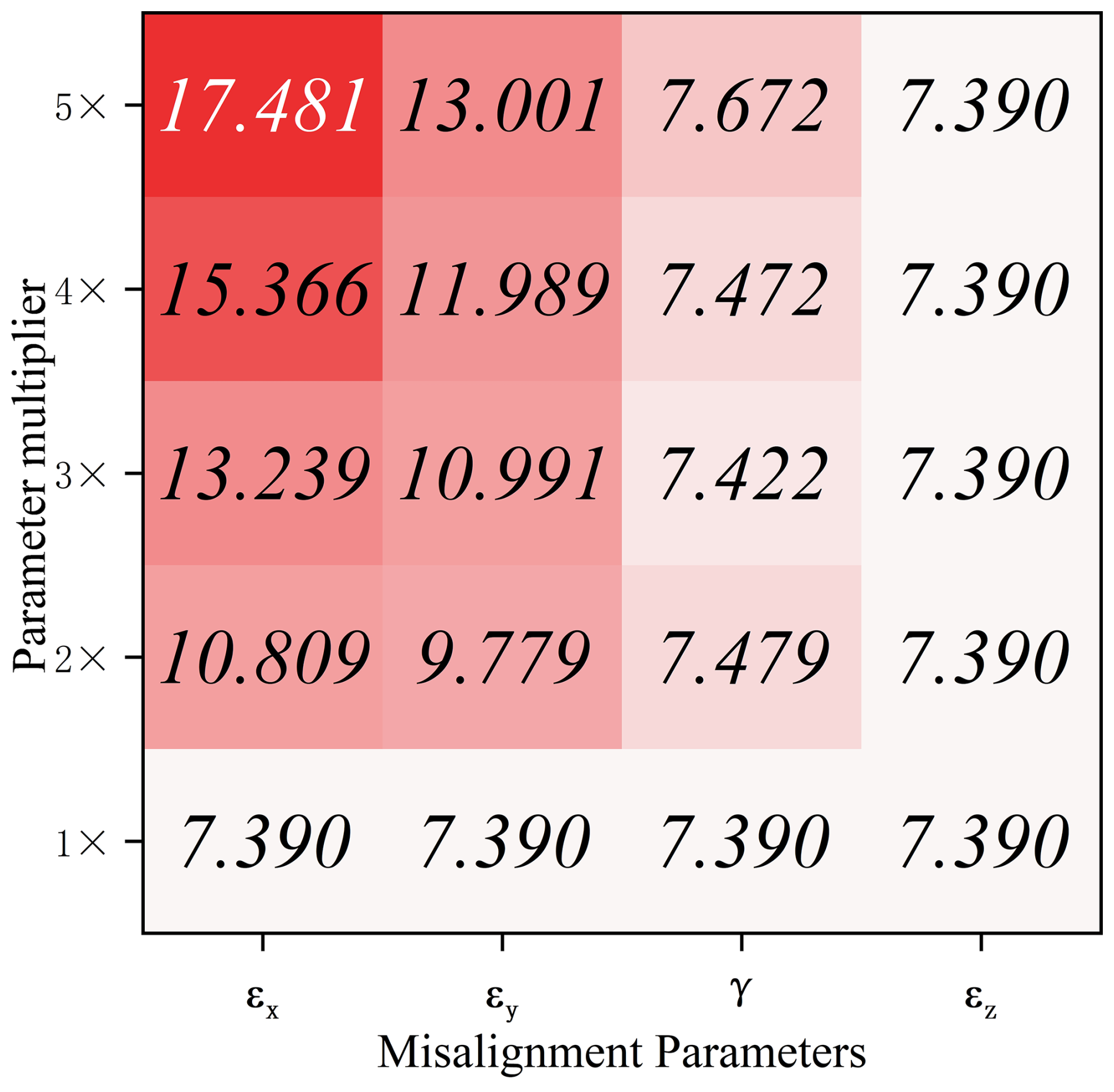
This section considers six coupling-misalignment cases. ϵx is 0.05, ϵy is 0.05, ϵz is 0.25 mm, and γ is 0.25° for case 1. The amount of misalignment for case 2 to case 6 is 2 to 6 times that of case 1, respectively. First, the effect of each misalignment parameter is analyzed using case 1 as the reference condition. While keeping all other parameters constant, one misalignment parameter at a time is increased by specified factors to investigate the independent effects of each parameter on the quasi-static contact characteristics of the gear pair. As shown in Fig. 7, the horizontal axis represents different coupling-misalignment parameters, and the vertical axis represents the magnification factor relative to the case-1 reference condition, where 1× denotes the reference condition, and 2× to 5× represent values that are 2 to 5 times the reference value, respectively. This single-factor control method effectively eliminates the coupled effects caused by simultaneous changes in different misalignment parameters, thereby allowing for a comparison of the independent effects of each parameter on meshing stiffness. The results show that the extent of the influence of different coupling-misalignment parameters on meshing stiffness varies significantly, with ϵx having the most significant effect, followed by ϵy, while γ has a relatively minor effect, and ϵz has no significant effect on meshing stiffness. As ϵx and ϵy increase, the meshing stiffness exhibits a generally pronounced upward trend, indicating a strong positive correlation between these parameters and meshing stiffness; in contrast, the effect of γ on meshing stiffness is weaker, and its variation does not follow a strictly monotonic pattern. The primary reason for this is that the meshing misalignment of a gear pair is more sensitive to torsional deformation of the shaft system, whereas deformation in the axial direction has a relatively limited effect on meshing misalignment. Furthermore, different misalignment parameters affect the form and extent of shaft system deformation in varying ways, which in turn leads to differing degrees of influence on meshing misalignment and meshing stiffness. It can thus be seen that the quasi-static contact characteristics of the gear pair are primarily sensitive to ϵx and ϵy, while the effects of γ and ϵz are relatively limited. It should be noted that this section primarily analyzes the impact of changes in coupling-misalignment parameters on the quasi-static contact characteristics of the gear pair, with a focus on the variation patterns of meshing stiffness. Since meshing stiffness is a critical internal excitation parameter in subsequent dynamic analyses, its variation will further influence the system's dynamic response. Therefore, the patterns of parameter sensitivity revealed by this single-factor quasi-static analysis can provide a basis for subsequently assessing the relative effects of different coupling-misalignment parameters on the system's dynamic response.
As shown in Fig. 9, the g2 gear pair mesh stiffness curve exhibits not only short-period fluctuations, that is, fluctuations at the mesh frequency, but also obvious long-period fluctuations. The fluctuation frequency is the same as the coupling-misalignment force frequency, which is twice the shaft frequency. The results indicate that the contact condition of the g2 gear pair is governed by the force/moment excitation induced by coupling misalignment. With increasing misalignment, the shaft undergoes greater bending deformation, which further intensifies the fluctuation of mesh stiffness over one rotational period. For the left helical gear, since complete tooth surface contact is established during meshing cycle intervals 42 to 86 and 142 to 186, the actual contact line length does not change, and so the mesh stiffness is the same. Outside these intervals, the reduction in mesh stiffness results from partial disengagement of the tooth surface, and the curve shape changes significantly. For the right helical gear, during mesh cycles 42 to 86 and 142 to 186, the actual contact line length changes due to partial disengagement of the tooth surface, which markedly alters both the level of mesh stiffness and its fluctuation characteristics.
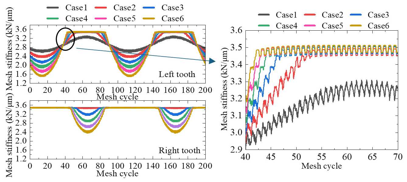
Since the misalignment force/moment of the coupling changes periodically with variations in the rotational angle, the load-induced deformation of the system also varies over the period corresponding to twice the shaft frequency. Figure 10 shows the mesh misalignment of the g2 gear pair in the 13th and 66th mesh cycles. In the 13th mesh cycle, for the g2 gear pair, the left tooth exhibits markedly greater mesh misalignment than the right, and this left-side misalignment increases progressively with increasing coupling misalignment. Misalignment-induced forces and moments have an increasing influence on the bending deformation of the shaft carrying the g2 gear pair, causing the disengaged area on the left tooth surface to increase and the actual contact line length to decrease. Therefore, the mesh stiffness of the left tooth decreases significantly with the increase in misalignment in the 13th mesh cycle. Because the peak mesh misalignment on the right tooth is only 11.14 µm across the six prescribed misalignment levels and because the tooth surface remains in complete contact during the 13th meshing cycle, the right mesh stiffness remains almost unchanged as the misalignment level increases.
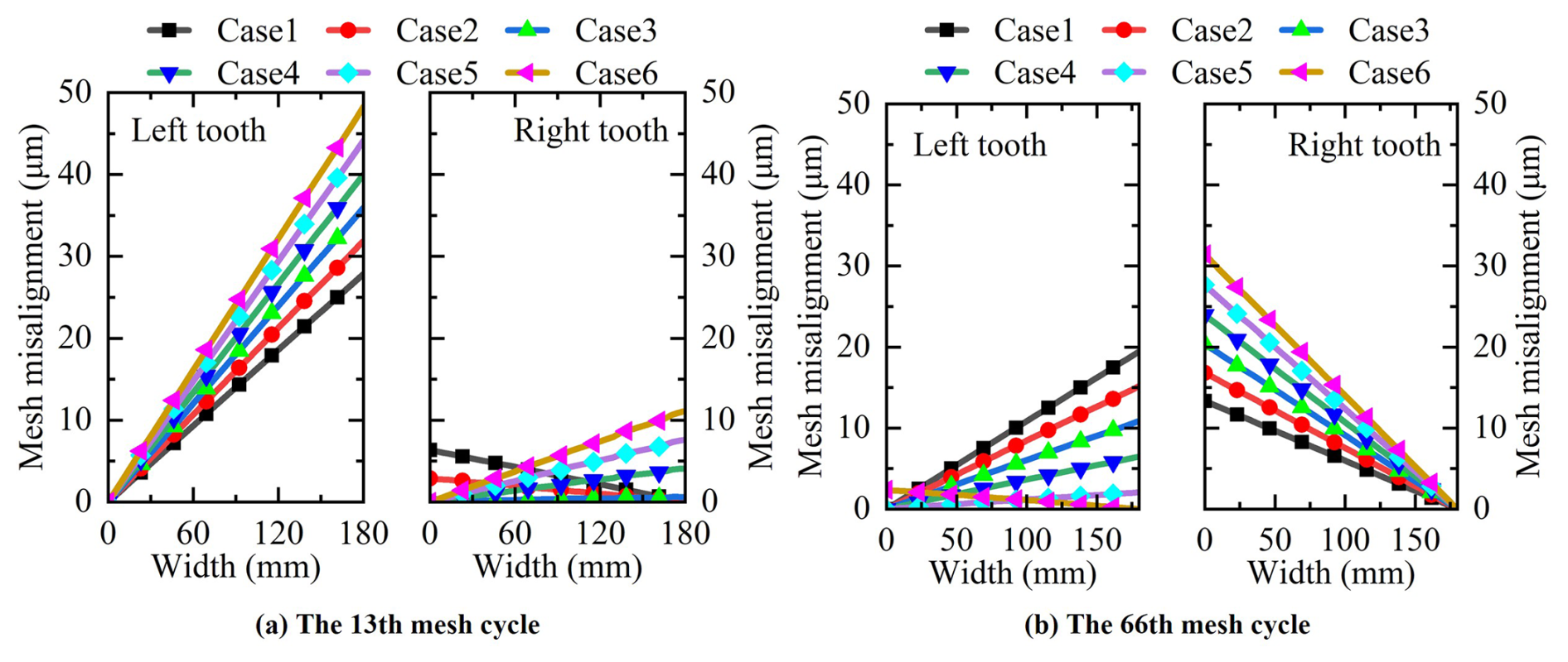
With increasing coupling misalignment, the force/moment excitation induced by misalignment exerts a progressively stronger effect on the bending deformation of the shaft carrying the g2 gear pair. In the 66th mesh cycle, as the coupling-misalignment level rises, the g2 left tooth exhibits a gradual reduction in mesh misalignment magnitude; in case 6, the peak misalignment is displaced toward the left-hand region of the tooth surface. The mesh misalignment of the right tooth surface gradually increases with the increase in coupling misalignment. Because the left tooth mesh misalignment is smaller in cases 2 to 6, the mesh stiffness of the left tooth of the g2 gear pair is the same in this mesh cycle; the curve shape is also the same, and the tooth surfaces are in complete contact. Figure 11 presents the tooth surface load pattern calculated for the g2 gear pair during the 66th mesh cycle under different coupling-misalignment amounts. In case 1, disengagement is observed only on the left tooth surface, and the mesh stiffness is significantly lower than that in the other misalignment cases. The shaft carrying the g2 gear pair bends under the combined action of the meshing force, and the force/moment excitation induced by misalignment. The bending deformation caused by its meshing force is symmetrically distributed along the axis. As the misalignment force/moment increases, the influence on shaft bending deformation gradually increases, and the differences in mesh misalignment and tooth surface load distribution between the left and right increase accordingly.
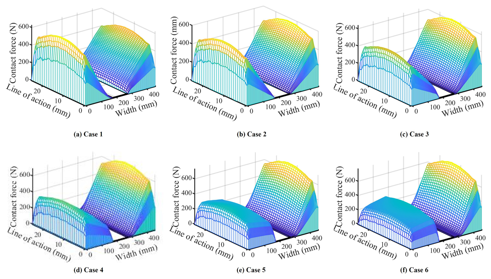
By comparing the tooth surface contact states shown in Fig. 11 with the face width mesh misalignment at the 66th meshing cycle in Fig. 10, it can be observed that the central relief groove of the herringbone gear separates the left- and right-hand helical tooth surfaces. Therefore, its meshing behavior can be approximately regarded to be the combined action of two single-helical gear pairs, allowing the mesh misalignment and contact states of the left and right tooth surfaces to be analyzed separately. It should be noted that the mesh misalignment of the gear pair is not governed by a single factor but results from the combined effects of the tooth meshing force under the actual loading condition and the additional forces and moments induced by coupling misalignment. Consequently, the contact states of the left and right tooth surfaces do not exhibit a simple positive correlation with the magnitude of coupling misalignment. In case 1, the coupling eccentricity is relatively small, and the additional forces and moments induced by the misalignment have only a limited influence on the shaft system attitude. Therefore, the mesh misalignment of the gear pair is mainly governed by the tooth meshing force under the actual loading condition. Although the mesh misalignment values of the left and right tooth surfaces are relatively close, the misalignment on the left tooth surface is slightly larger, resulting in local disengagement, whereas the right tooth surface maintains a relatively favorable contact state. This indicates that tooth disengagement in a herringbone gear cannot be determined solely by the magnitude of coupling eccentricity but depends primarily on the actual distribution of mesh misalignment between the left and right tooth surfaces under the combined effects of the tooth meshing force and coupling-misalignment excitation. Further examination of the results at the 66th meshing cycle in Fig. 10 shows that, as the coupling eccentricity increases, the additional forces and moments induced by the misalignment gradually increase, and their influence on the displacement and orientation of the shaft system becomes more pronounced. As a result, the original mesh misalignment distribution dominated by the tooth meshing force is progressively altered. During this process, the mesh misalignment of the left and right tooth surfaces exhibits opposite trends: the mesh misalignment on the left tooth surface gradually decreases with increasing misalignment excitation, whereas that on the right tooth surface gradually increases. Correspondingly, the tooth-surface contact states shown in Fig. 11 also change significantly, evolving from local disengagement on the left tooth surface with good contact on the right tooth surface in case 1 to good contact on the left tooth surface with disengagement on the right tooth surface in case 6. These results demonstrate that, for a herringbone gear transmission system, the magnitude of coupling misalignment itself does not directly determine the tooth surface contact state. Instead, coupling misalignment modifies the additional forces and moments acting on the shaft system, which interact with the tooth meshing force to redistribute the mesh misalignment between the left and right tooth surfaces, ultimately leading to corresponding changes in the tooth contact region and local load-carrying state. The above analysis shows that the system deformation and tooth surface contact state vary under coupling-misalignment forces and moments over the period corresponding to twice the shaft frequency. The mesh stiffness exhibits long-period fluctuations. With increasing misalignment magnitude, the mesh stiffness fluctuation of the gear pair, which is greatly affected by the misalignment force/moment, will also increase. Larger misalignment forces and moments lead to greater differences in mesh misalignment between the left and right tooth surfaces and a more asymmetric tooth surface load distribution. Under the combined effect of meshing force and misalignment force/moment, the mesh misalignment of the gear pair within certain mesh cycle ranges is small. When the tooth surface reaches a complete contact state, the actual contact line length is the same, and the mesh stiffness within this range is the same.
4.2 Effect of load torque
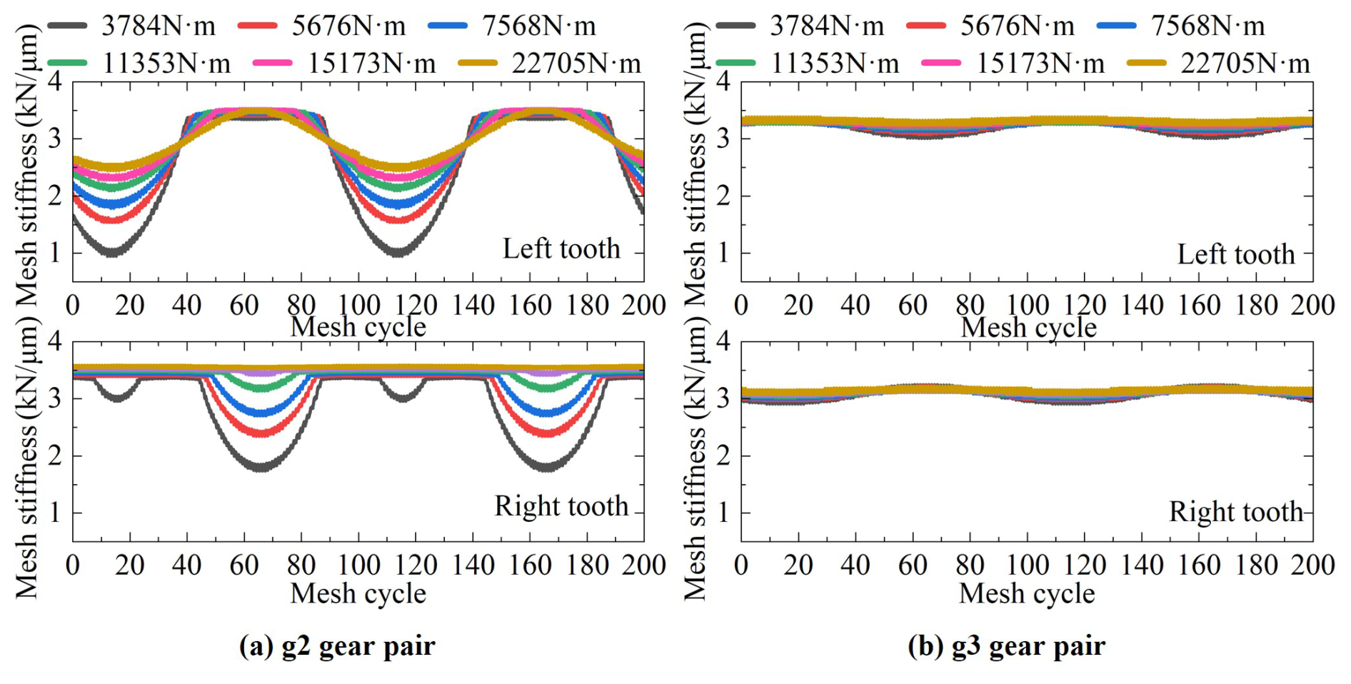
The load torque determines the meshing force of the gear pair. Shaft deformation at the gear pair location is governed jointly by meshing force excitation and the force/moment components generated by coupling misalignment. In this section, the coupling misalignment ϵx is 0.15, ϵy is 0.15, ϵz is 0.75 mm, and γ is 0.75°. The quasi-static characteristics of the gear system are analyzed at load torques of 22 705, 15 137, 11 353, 7568, 5676, and 3784 N m−1. Figure 12 shows the mesh stiffness of the gear pair under different load torques. As the load torque gradually increases, the g2 and g3 gear pairs exhibit progressively reduced mesh stiffness fluctuations. Owing to the shorter distance between the g2 left helical gear and the coupling, it is more affected by coupling misalignment. Across the load torque levels considered, mesh stiffness fluctuation is more pronounced in the left helical gear than in the right. The tooth surfaces of the g2 left helical gear are in complete contact during certain mesh cycles, and so the mesh stiffness value does not change significantly. The g2 right helical gear has a disengaged area on the tooth surface during certain mesh cycles, and the mesh stiffness value changes significantly. Since the g3 gear pair has partial disengagement during the rotation period, the long-term fluctuation trend of the mesh stiffness curve under different load torques is sinusoidal. The greater distance between the g3 gear pair and the coupling weakens the influence of the misalignment-induced force. Therefore, the g3 gear pair has smaller long-term fluctuations compared with the g2 gear pair.
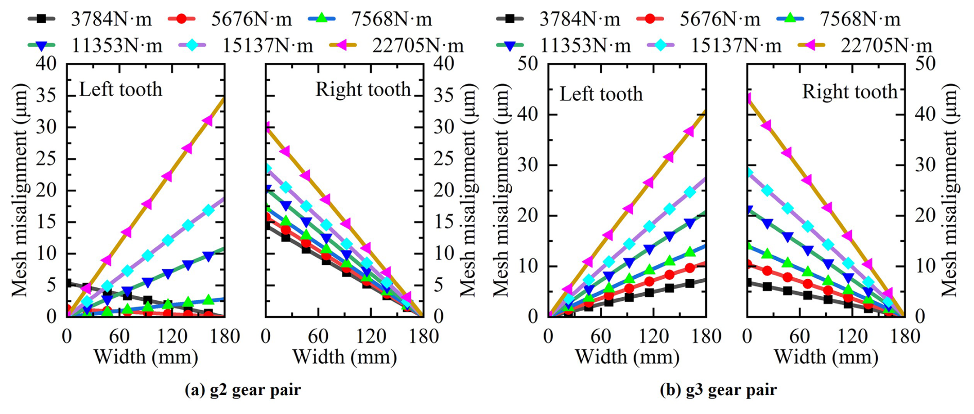
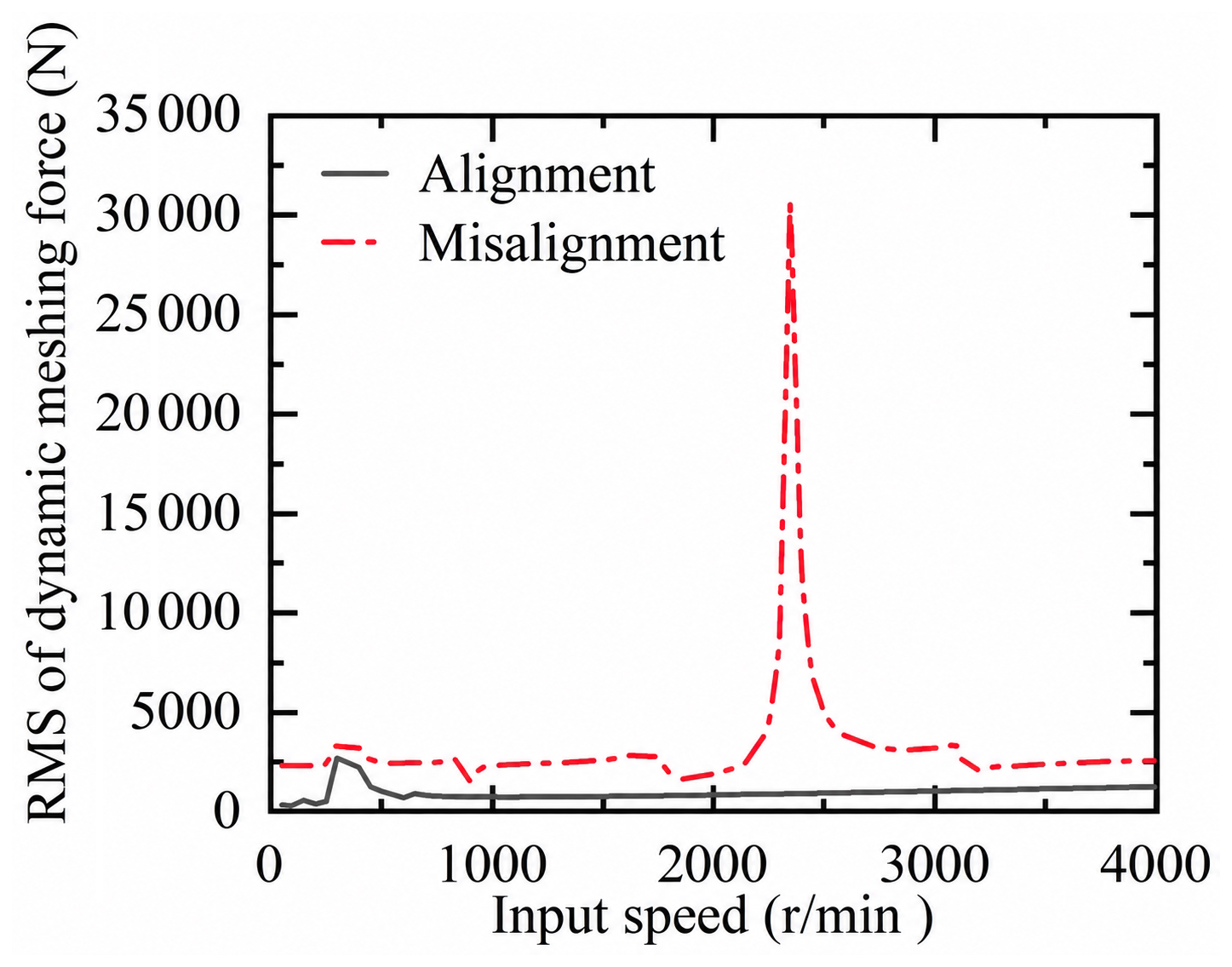
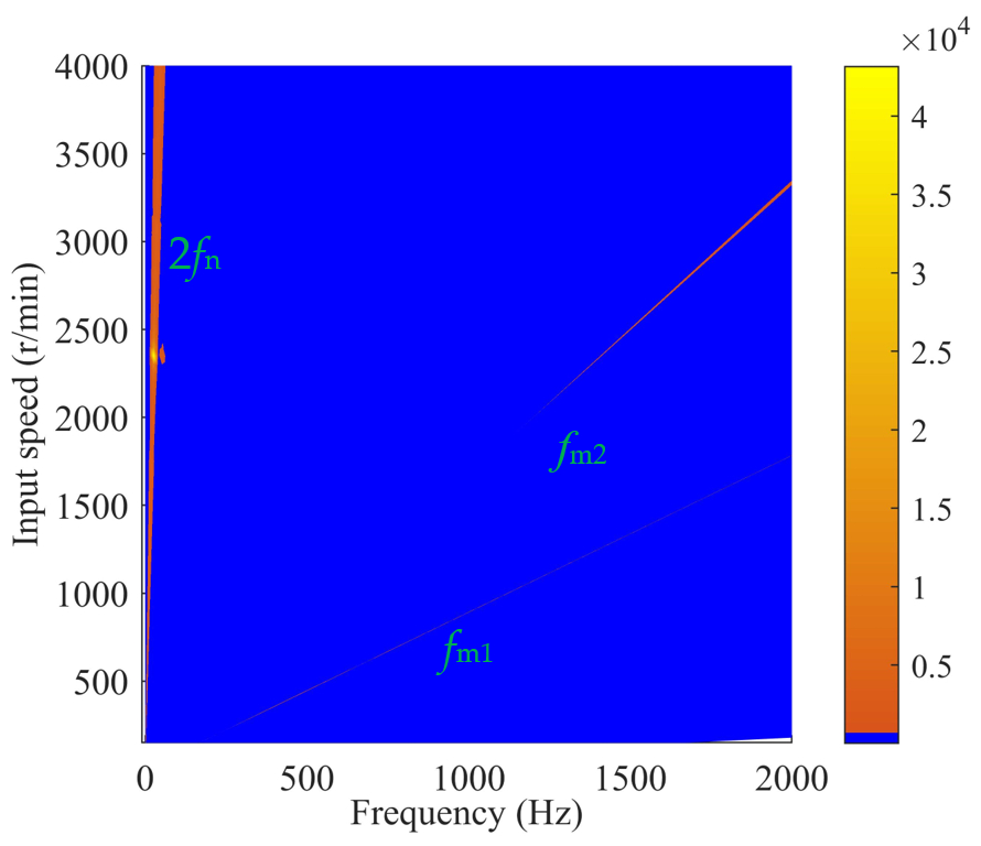
Figure 15Spectral map of the dynamic meshing force of the g2 gear pair over 0 to 4000 r min−1.
In general, higher load torque produces larger system deformation under load and correspondingly greater mesh misalignment. The formation of a disengagement region on the tooth surface reduces the actual contact line length; the mesh stiffness value will decrease, and the fluctuation amount will increase. However, when the coupling is misaligned, the misalignment force/moment and the gear pair meshing force jointly affect the system deformation. The meshing force is very small under a light load. The system deformation is mainly caused by the coupling-misalignment force/moment. Consequently, an extensive region of contact loss develops on the tooth surface. The actual contact line length changes with the mesh cycle, and the mesh stiffness value also changes accordingly, and so the long-period fluctuation increases under light loads. As the load torque gradually increases, the gear pair meshing force also increases. As the meshing force increases, the disengaged area on the tooth surface decreases until full contact is reached. Only limited variation occurs in the actual tooth surface contact line length, and so the mesh stiffness value changes little, and the long-period fluctuation is reduced.
Figure 13 shows the mesh misalignment of the gear pair under different load torques during the 66th mesh cycle. As the load torque increases, the influence of the g2 gear pair meshing force on the bending deformation of the shaft increases, and the mesh misalignment discrepancy between the left and right teeth is gradually reduced. For the g3 gear pair, the mesh misalignment is symmetrically distributed under the six load torques and is less affected by the misalignment force. As the torque increases, the meshing force increases, increasing the mesh misalignment. The proximity of the right tooth surface to the power output end causes the mesh misalignment associated with torsional deformation of the shaft to be slightly larger than that on the left tooth surface.
This section shows that coupling misalignment causes the mesh stiffness of the gear pair to fluctuate at twice the shaft frequency. Since mesh stiffness is an important source of excitation in the gear system, it can be inferred that the gear system dynamic model incorporating coupling misalignment presented below contains an excitation component at twice the shaft frequency.
5.1 System differential equation of motion
According to the study by Gong et al. (2022b), the differential equation of motion of the gear system considering coupling misalignment is established, and its matrix form is given in Eq. (22). t is the time required for the slowest shaft in the system to rotate one revolution. The coupling-misalignment forces and moments are included as excitation terms in the gear system dynamics model, where Fc(t) represents the coupling-misalignment excitation vector. According to the above misalignment excitation equation, it is a low-frequency excitation associated with the rotational angle. Mglobal, Cglobal, and Kglobal are the system mass, damping, and stiffness matrices, respectively. x, , and are displacement, velocity, and acceleration, respectively. e(t) is the meshing error. Since the research object of this paper includes multiple meshing excitations and coupling-misalignment excitations, to improve calculation efficiency, the parameters of Eq. (22) are normalized as shown in Eq. (23). Here, represents the mean stiffness, and Δ denotes its fluctuation. The system excitation force is calculated using the frequency domain solution method. The system vibration responses to time-varying mesh stiffness excitation, error excitation, and coupling-misalignment excitation in each gearbox are calculated separately using Fourier series expansions. The mesh stiffness, transmission error, and coupling-misalignment excitations are all expanded in Fourier series, with the gear meshing frequency taken as the fundamental frequency. The detailed formulation of the dynamic model and the corresponding solution procedure are provided in Gong et al. (2025). The system vibration response is then obtained by superposing the vibration responses associated with identical nodes and corresponding degrees of freedom. The dynamic meshing force of the gear pair is calculated using Eq. (24), where km and cm denote the mesh stiffness and mesh damping coefficient, respectively; em is the composite mesh error; and DTE is the dynamic transmission error. The vector qm represents the nodal vibration displacements of the gears, and V is the projection vector along the line of action.
5.2 Effect of combined high- and low-frequency excitation
Figure 14 shows the root mean square (rms) of the dynamic meshing force of the g2 left helical gear. Coupling-misalignment excitation produces a new resonance peak for the g2 gear pair at 2350 r min−1. In the resonance region induced by misalignment excitation, the linear model predicts a marked increase in dynamic meshing force fluctuations. The dynamic meshing force spectral map of the g2 gear pair is shown in Fig. 15. A distinct frequency band at twice the shaft frequency (2fn) is observed in the spectrum. fn denotes the rotational frequency of the shaft carrying the coupling. The maximum amplitude in the dynamic meshing force spectral map of the g2 gear pair appears at 2350 r min−1 in the band at twice the shaft frequency. The mesh frequency band, fm1, of the adjacent gearbox GB1 appears in the dynamic meshing force spectrum of the g2 gear pair, which shows a coupling resonance between the GB1 and GB2 gearboxes at 2300 r min−1.
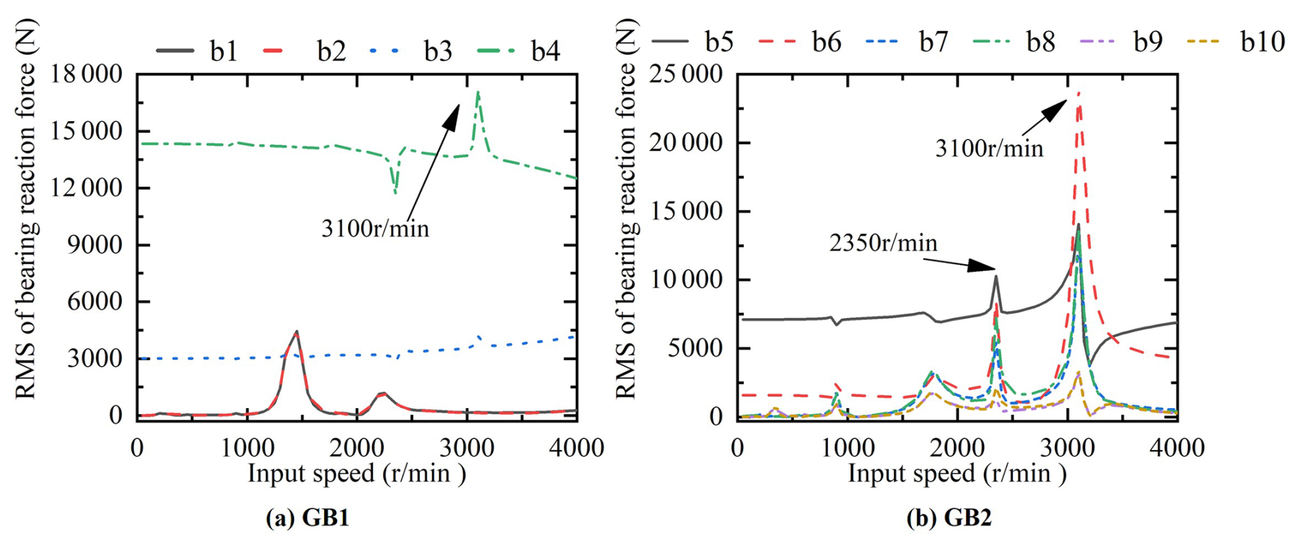
The bearing reaction force under coupling misalignment is characterized in Fig. 16 using its rms value. The misalignment of the coupling significantly increases the root mean square reaction force of the b3 and b4 bearings in the GB1 gearbox that are closer to the coupling, and a larger resonance peak appears at 3100 r min−1. The misalignment of the coupling significantly increases the root mean square reaction force of the b5 to b10 bearings in the GB2 gearbox, and large resonance peaks appear at 2350 and 3100 r min−1. As the distance from the coupling gradually increases, the root mean square of the bearing reaction force gradually decreases, and the vibration weakens. The vibration response of the b9 and b10 bearings farthest from the coupling is also affected by coupling misalignment.
5.3 Effect of coupling misalignment
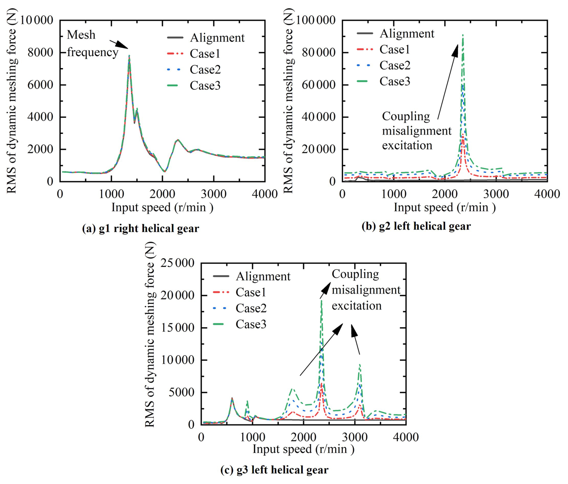
Figure 17 shows the root mean square of the dynamic meshing force under different coupling misalignments. For the g1 right helical gear, the RMS dynamic meshing force curves coincide under the aligned condition and cases 1 to 3. This is because the GB1 gearbox bearings have high stiffness and are unaffected by coupling misalignment. The mesh frequency causes the resonance peak at 1350 r min−1. The dynamic meshing force of the g2 left helical gear fluctuates periodically at twice the shaft frequency. The amount of fluctuation increases with the amount of misalignment. Therefore, the RMS dynamic meshing force of the g2 left helical gear increases as the coupling misalignment becomes larger. Notably, when the coupling-misalignment excitation produces resonance at 2350 r min−1, the resonance peaks for the aligned condition and cases 1 to 3 are 909.06, 30 579.46, 60 550.19, and 91 213.82 N, respectively. These results indicate a progressive enhancement of the vibration response of the g2 left helical gear. By contrast, the g3 left helical gear shows little variation in RMS dynamic meshing force within 0 to 850 r min−1 as the coupling misalignment increases. This is because the vibration in this speed range is mainly caused by mesh frequency excitation and is less affected by coupling-misalignment excitation. Between 850 and 4000 r min−1, resonance is caused by coupling-misalignment excitation. As misalignment increases, the resonance peak amplitude increases, and gear pair vibration intensifies. The change in coupling misalignment does not change the resonance speed of the gear pair.
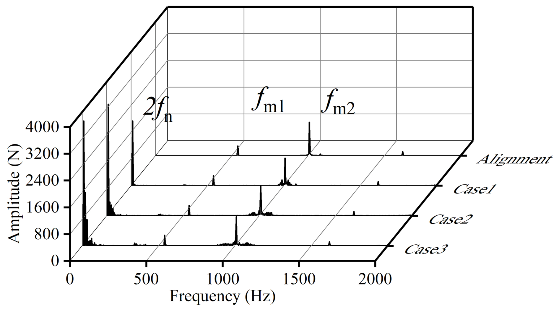
Figure 18Dynamic meshing force spectrum of the g2 left helical gear under different coupling misalignments at 900 r min−1.
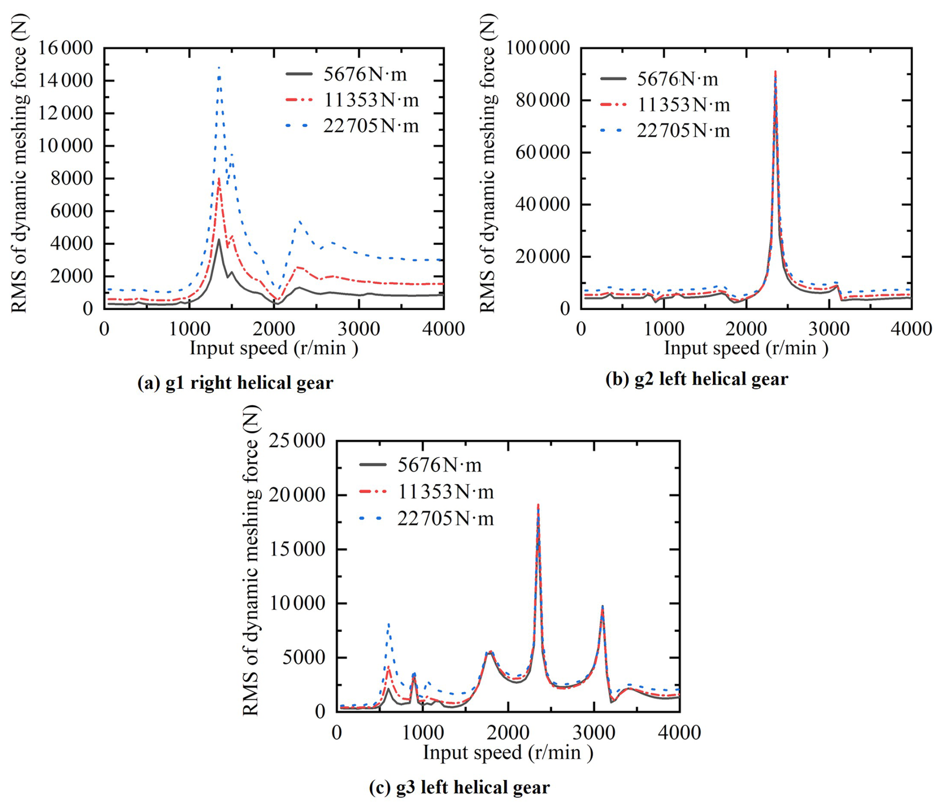
Figure 18 shows the meshing force spectrum of the g2 left helical gear under different coupling misalignments. The corresponding amplitudes of the component at twice the shaft frequency, 2fn, in cases 1 to 3 are 1936.64, 3337.74, and 3735.16 N, respectively. This shows that, as the amount of misalignment increases, the impact of coupling-misalignment excitation on the vibration response of the gear pair increases. In the dynamic meshing force spectrum under cases 1∼3, the amplitude of the adjacent gearbox mesh frequency fm1 and the amplitude of its mesh frequency fm2 do not change significantly with the change in the misalignment amount. The component at the mesh frequency fm2 is modulated by the component at twice the shaft frequency, 2fn, producing a sideband near fm2.
5.4 Effect of load torque
The coupling misalignment ϵx is 0.15, ϵy is 0.15, ϵz is 0.75 mm, and γ is 0.75°. On this basis, the vibration response characteristics of the gear system under different load torques are analyzed in Fig. 19. Three load torques of 5676, 11 353, and 22 705 N m−1 are selected. For the g1 right helical gear, the rms dynamic meshing force increases with load torque, and the increase is more obvious at the resonance speed. This is because the resonance peak of the g1 right helical gear in the range of 0 to 4000 r min−1 is excited by its mesh frequency. Higher torque produces a larger excitation force in the gear pair, a higher rms dynamic meshing force, and more severe vibration. The resonance peak amplitude caused by the mesh frequency of the g2 and g3 gear pairs below 1000 r min−1 increases with the increase in load torque. Since the misalignment excitation of the coupling is the same under different load torques, the resonance peak value of the g2 and g3 gear pairs caused by the misalignment excitation does not change much under the three load torques. The load torque has little effect on the resonance speed of the gear pair. It mainly affects the vibration response under mesh frequency excitation. The greater the torque, the more severe the vibration.
This paper proposes an efficient quasi-static contact analysis model for marine gear systems considering coupling misalignment. The coupling misalignment excitation is introduced into the gear system differential equation of motion. The quasi-static contact behavior and dynamic characteristics of the marine gear system are analyzed under different coupling-misalignment and load torque conditions. The main research conclusions are as follows:
-
Owing to periodic variations in coupling-misalignment forces and moments, the mesh stiffness fluctuates over long periods. As the amount of misalignment increases, long-period fluctuations in mesh stiffness will also increase. A higher level of misalignment-induced force/moment excitation produces more pronounced shaft bending deformation, accompanied by larger differences between the left and right tooth surfaces in mesh misalignment and tooth surface load distribution of the double-helical gear pair.
-
The gear pair meshing force and misalignment force/moment jointly affect the system deformation. Under light loads, the quasi-static contact behavior of the gear pair is more susceptible to coupling misalignment, causing the tooth surface to disengage and the long-period fluctuations in mesh stiffness to increase. As the torque gradually increases, system deformation is primarily governed by the meshing force. For the symmetrically supported double-helical gear pair, the mesh misalignment is symmetrically distributed between the left and right tooth surfaces, and the disengaged area decreases until it disappears.
-
As the rotational speed gradually increases, the coupling misalignment excitation causes the system to resonate. In the resonance region induced by misalignment excitation, the linear model predicts a marked increase in dynamic meshing force fluctuations. Under the action of combined high- and low-frequency excitations, the modulation phenomenon is evident in the vibration response spectrum of the gear pair. When the coupling is misaligned, the bearings on both sides exhibit strong vibration dominated by a component at twice the shaft frequency.
-
As the coupling misalignment increases, the system vibration gradually intensifies. The change in coupling misalignment does not change the resonance speed of the gear pair. The load torque has little effect on the system resonance speed. It mainly affects the system vibration response under mesh-frequency excitation.
In future research, we will focus on enhancing experimental validation, exploring additional types of misalignments, and evaluating long-term system performance. Furthermore, nonlinear effects will be addressed by incorporating gear backlash and two-way iterative coupling between tooth contact states and vibration responses, with surrogate models used to improve computational efficiency. Extending the analysis to varying lubrication regimes and multiple operating scenarios will further enhance its practical applicability, supporting reliability assessment and maintenance planning for marine gear systems. These future directions build upon the findings of this work and aim to refine the model for real-world implementation.
The datasets generated and analyzed during this study are available from the corresponding author upon reasonable request. They are not publicly available due to their large size and the inclusion of detailed simulation models, model parameters, and intermediate computational results.
Jingyi Gong conceived the study, designed the research framework, developed the theoretical model, interpreted the results, and prepared the original draft. Kaiyang Chen contributed to the model development, parameter and boundary condition determination, numerical calculations, and methodology writing. Jingyi Gong, Kaiyang Chen, and Ruikai Dai jointly performed the data processing and result analysis, while Ruikai Dai also verified the reliability and consistency of the calculations. Haipeng An reviewed and revised the paper for technical accuracy, logical structure, grammar, and academic expression. Guanghao Dai prepared and optimized the figures, tables, and data visualizations. Bing Yuan contributed to the model validation, result comparison, proofreading, reference format checking, and the final consistency review. All of the authors discussed the results and approved the final paper.
The contact author has declared that none of the authors has any competing interests.
Publisher's note: Copernicus Publications remains neutral with regard to jurisdictional claims made in the text, published maps, institutional affiliations, or any other geographical representation in this paper. The authors bear the ultimate responsibility for providing appropriate place names. Views expressed in the text are those of the authors and do not necessarily reflect the views of the publisher.
The authors received financial support from the Natural Science Basic Research Program of Shaanxi Province (grant nos. 2025JC-YBQN-651 and 2025JC-YBMS-399) and the Stable Support Project Funding (grant no. KJD231170).
This paper was edited by Pengyuan Zhao and reviewed by two anonymous referees.
Al-Hussain, K. M.: Dynamic stability of two rigid rotors connected by a flexible coupling with angular misalignment, J. Sound Vib., 266, 217–234, https://doi.org/10.1016/S0022-460X(02)01627-9, 2003.
Al-Hussain, K. M. and Redmond, I.: Dynamic response of two rotors connected by rigid mechanical coupling with parallel misalignment, J. Sound Vib., 249, 483–498, https://doi.org/10.1006/jsvi.2001.3866, 2002.
Chen, H., Zhou, R.-P., Lei, J.-S., Jiang, H.-Y., and Ye, J.: Theoretical and experimental study of the torque impact and shaft response during the rapid engaging process of a gas turbine, Shock Vib., 2022, 7555053, https://doi.org/10.1155/2022/7555053, 2022.
Fu, C., Lu, K., Yang, Y., Xie, Z., and Ming, A.: Nonlinear vibrations of an uncertain dual-rotor rolling bearings system with coupling misalignment, J. Nonlinear Math. Phys., 29, 388–402, https://doi.org/10.1007/s44198-022-00044-x, 2022.
Gibbons, C. B.: Coupling misalignment forces, in: Proceedings of the 5th Turbomachinery Symposium, Texas A&M University, College Station, Texas, USA, 12–14 October 1976, 111–116, https://doi.org/10.21423/R10T1X, 1976.
Gong, J., Liu, G., Liu, L., and Yang, L.: Review article: Research on coupled vibration of multi-engine multi-gearbox marine gearing, Mech. Sci., 12, 393–404, https://doi.org/10.5194/ms-12-393-2021, 2021.
Gong, J., Liu, G., Liu, L., Yuan, B., Yang, L., and Ren, P.: Experimental study on vibration characteristics of double-helical gearbox with isolators, J. Mech. Sci. Technol., 36, 4379–4393, https://doi.org/10.1007/s12206-022-0803-5, 2022a.
Gong, J., Liu, G., Yuan, B., Liu, L., Yang, L., and Wu, F.: Coupled dynamics characteristics analysis of the marine multi-gearbox system under multi-source excitation, Adv. Mech. Eng., 14, 16878132221092999, https://doi.org/10.1177/16878132221092999, 2022b.
Gong, J., Yuan, B., and Liu, G.: A study on contact and vibration characteristics of marine Cross-Connect gear considering system deformation and multiple operating modes, Int. J. Electr. Power Energy Syst., 170, 110847, https://doi.org/10.1016/j.ijepes.2025.110847, 2025.
Guan, H., Wang, P., Xiong, Q., Ma, H., Zhou, S., Mu, Q., Zeng, Y., and Chen, Y.: Modeling of misaligned bearing induced by coupling misalignment and assembly errors and vibration analysis in dual-rotor system, Mech. Syst. Signal Process., 230, 112656, https://doi.org/10.1016/j.ymssp.2025.112656, 2025.
Huang, W., Hu, H., and Ma, H.: Dynamic modeling and response analysis of cracked herringbone gear transmission systems with installation errors, Mech. Mach. Theory, 206, 105924, https://doi.org/10.1016/j.mechmachtheory.2025.105924, 2025.
Huang, Z., Zhou, J., Yang, M., and Zhang, Y.: Vibration characteristics of a hydraulic generator unit rotor system with parallel misalignment and rub-impact, Arch. Appl. Mech., 81, 829–838, https://doi.org/10.1007/s00419-010-0453-4, 2011.
Hujare, D. P. and Karnik, M. G.: Vibration responses of parallel misalignment in Al shaft rotor bearing system with rigid coupling, Mater. Today Proc., 5, 23863–23871, https://doi.org/10.1016/j.matpr.2018.10.178, 2018.
Jiang, Y., Wang, Y., Hou, L., Zhang, T., Zhang, Z., Zhang, M., Lin, R., Jin, Y., and Song, J.: A modified dynamic model of rotor systems with spline coupling considering misalignment, Eng. Fail. Anal., 170, 109251, https://doi.org/10.1016/j.engfailanal.2024.109251, 2025.
Jin, Y., Liu, Z., Yang, Y., Li, F., and Chen, Y.: Nonlinear vibrations of a dual-rotor-bearing-coupling misalignment system with blade-casing rubbing, J. Sound Vib., 497, 115948, https://doi.org/10.1016/j.jsv.2021.115948, 2021.
Kumar, P. and Hirani, H.: Misalignment effect on gearbox failure: An experimental study, Measurement, 169, 108492, https://doi.org/10.1016/j.measurement.2020.108492, 2021.
Lee, Y. S. and Lee, C. W.: Modelling and vibration analysis of misaligned rotor-ball bearing systems, J. Sound Vib., 224, 17–32, https://doi.org/10.1006/jsvi.1997.1301, 1999.
Li, M. and He, L.: The dynamics of a parallel-misaligned and unbalanced rotor system under the action of non-linear oil film forces, Proc. Inst. Mech. Eng. S., 224, 1875–1889, https://doi.org/10.1243/09544062JMES1916, 2010.
Li, Z., Jiang, J., and Tian, Z.: Stochastic dynamics of a nonlinear misaligned rotor system subject to random fluid-induced forces, J. Comput. Nonlin. Dyn., 12, 011004, https://doi.org/10.1115/1.4034124, 2017.
Lu, K., Jin, Y., Huang, P., Zhang, F., Zhang, H., Fu, C., and Chen, Y.: The applications of POD method in dual rotor-bearing systems with coupling misalignment, Mech. Syst. Signal Process., 150, 107236, https://doi.org/10.1016/j.ymssp.2020.107236, 2021.
Ma, H., Wang, X., Niu, H., and Wen, B.: Oil-film instability simulation in an overhung rotor system with flexible coupling misalignment, Arch. Appl. Mech., 85, 893–907, https://doi.org/10.1007/s00419-015-0998-3, 2015.
Ma, X., Li, Z., Xiang, J., Chen, C., and Huang, F.: Vibration characteristics of rotor system with coupling misalignment and disc-shaft nonlinear contact, Mech. Syst. Signal Process., 223, 111839, https://doi.org/10.1016/j.ymssp.2024.111839, 2025.
Meng, H., Wang, Z. T., Li, S. Y., Zhao, N. B., and Jin, G.: The simulation study on dynamic characteristics of COGAG engaging process, Adv. Mater. Res., 960–961, 1442–1445, https://doi.org/10.4028/www.scientific.net/AMR.960-961.1442, 2014.
Moghe, S. M. and Mahure, A. N.: Study of vibration response of coupling under misalignment condition – a review, International Journal of Research in Advent Technology, 5, 50–53, 2017.
Nan, G., Yang, S., and Yu, D.: Misalignment and rub-impact coupling dynamics of power turbine rotor with offset disk, Appl. Sci., 14, 1298, https://doi.org/10.3390/app14031298, 2024.
Patel, T. H. and Darpe, A. K.: Vibration response of misaligned rotors, J. Sound Vib., 325, 609–628, https://doi.org/10.1016/j.jsv.2009.03.024, 2009a.
Patel, T. H. and Darpe, A. K.: Experimental investigations on vibration response of misaligned rotors, Mech. Syst. Signal Process., 23, 2236–2252, https://doi.org/10.1016/j.ymssp.2009.04.004, 2009b.
Pennacchi, P., Vania, A., and Chatterton, S.: Nonlinear effects caused by coupling misalignment in rotors equipped with journal bearings, Mech. Syst. Signal Process., 30, 306–322, https://doi.org/10.1016/j.ymssp.2011.11.020, 2012.
Prabhakar, S., Sekhar, A. S., and Mohanty, A. R.: Crack versus coupling misalignment in a transient rotor system, J. Sound Vib., 256, 773–786, https://doi.org/10.1006/jsvi.2001.4225, 2002.
Sekhar, A. S. and Prabhu, B. S.: Effects of coupling misalignment on vibrations of rotating machinery, J. Sound Vib., 185, 655–671, https://doi.org/10.1006/jsvi.1995.0407, 1995.
Wan, Z., Jing, J.-P., Meng, G., Yang, Y., and Bai, H.-Y.: Theoretical and experimental study on the dynamic response of multi-disk rotor system with flexible coupling misalignment, Proc. Inst. Mech. Eng. S., 226, 2874–2886, https://doi.org/10.1177/0954406211435582, 2012.
Wang, F., Dai, P., Wang, J., and Niu, L.: Vibration responses of the bearing-rotor-gear system with the misaligned rotor, Machines, 10, 267, https://doi.org/10.3390/machines10040267, 2022a.
Wang, N. and Jiang, D.: Vibration response characteristics of a dual-rotor with unbalance-misalignment coupling faults: Theoretical analysis and experimental study, Mech. Mach. Theory, 125, 207–219, https://doi.org/10.1016/j.mechmachtheory.2018.03.009, 2018.
Wang, P., Xu, H., Yang, Y., Ma, H., He, D., and Zhao, X.: Dynamic characteristics of ball bearing-coupling-rotor system with angular misalignment fault, Nonlinear Dynam., 108, 3391–3415, https://doi.org/10.1007/s11071-022-07451-1, 2022b.
Wang, Q., Xu, K., Huai, T., Ma, H., and Wang, K.: A mesh stiffness method using slice coupling for spur gear pairs with misalignment and lead crown relief, Appl. Math. Model., 90, 845–861, https://doi.org/10.1016/j.apm.2020.08.046, 2021.
Wu, K., Liu, Z., and Ding, Q.: Vibration responses of rotating elastic coupling with dynamic spatial misalignment, Mech. Mach. Theory, 151, 103916, https://doi.org/10.1016/j.mechmachtheory.2020.103916, 2020.
Xia, Y., Pang, J., Yang, L., Zhao, Q., and Yang, X.: Study on vibration response and orbits of misaligned rigid rotors connected by hexangular flexible coupling, Appl. Acoust., 155, 286–296, https://doi.org/10.1016/j.apacoust.2019.05.022, 2019.
Xu, H., Yang, Y., Ma, H., Luo, Z., Li, X., Han, Q., and Wen, B.: Vibration characteristics of bearing-rotor systems with inner ring dynamic misalignment, Int. J. Mech. Sci., 230, 107536, https://doi.org/10.1016/j.ijmecsci.2022.107536, 2022.
Xu, H., Zhao, X., Ma, H., Luo, Z., Han, Q., and Wen, B.: Vibration analysis of a gear-rotor-bearing system with outer-ring spalling and misalignment, J. Cent. South Univ., 31, 511–525, https://doi.org/10.1007/s11771-024-5576-9, 2024.
Xu, J., Cong, F., Tong, S., and Zhou, Y.: The influence of coupling misalignment on dynamic characteristics of helical gear system, in: Proceedings of the 2015 International Conference on Modeling, Simulation and Applied Mathematics, Phuket, Thailand, 23–24 August 2015, 20–24, https://doi.org/10.2991/msam-15.2015.5, 2015.
Xu, M. and Marangoni, R. D.: Vibration analysis of a motor-flexible coupling-rotor system subject to misalignment and unbalance, Part I: theoretical model and analysis, J. Sound Vib., 176, 663–679, https://doi.org/10.1006/jsvi.1994.1405, 1994.
Yang, L., Zeng, Q., Yang, H., Wang, L., Long, G., Ding, X., and Shao, Y.: Dynamic characteristic analysis of spur gear system considering tooth contact state caused by shaft misalignment, Nonlinear Dynam., 109, 1591–1615, https://doi.org/10.1007/s11071-022-07519-y, 2022.
Zhen, M., Tian, Y., Sun, T., Zhang, H., and Tan, C.: Nonlinear dynamics of two-span rotor-bearing system with flexible coupling misalignment, J. Mech. Eng., 56, 109–117, https://doi.org/10.3901/JME.2020.16.109, 2020.
Zhou, Z., Bin, G., Li, C., Gao, Y., and Bayjid Md, M.: Vibration responses of a two-span three-support rotor system with sliding bearing elevation change, Mech. Sci., 16, 375–390, https://doi.org/10.5194/ms-16-375-2025, 2025.
- Abstract
- Introduction
- Research objects and parameters
- Quasi-static contact analysis model for a gear system considering coupling misalignment
- Quasi-static characteristics of a gear system considering coupling misalignment
- Dynamic characteristics of a gear system considering coupling-misalignment excitation
- Discussion and conclusions
- Data availability
- Author contributions
- Competing interests
- Disclaimer
- Financial support
- Review statement
- References
- Abstract
- Introduction
- Research objects and parameters
- Quasi-static contact analysis model for a gear system considering coupling misalignment
- Quasi-static characteristics of a gear system considering coupling misalignment
- Dynamic characteristics of a gear system considering coupling-misalignment excitation
- Discussion and conclusions
- Data availability
- Author contributions
- Competing interests
- Disclaimer
- Financial support
- Review statement
- References