the Creative Commons Attribution 4.0 License.
the Creative Commons Attribution 4.0 License.
 | 19 Jan 2026
Design and motion planning of a compact direct-drive leg-wheel robot: DTransleg
Zhong Wei
Jinlin Guo
Jiwen Zhang
Jinyao Ren
Yang Yang
Sheng Xiang
Weixi Wang
Jia Liu
Aiguo Song
Existing articulated-leg leg-wheel robots suffer from complex structures and morphing mechanisms. To address this issue, this paper presents a transformable leg-wheel robot named DTransleg. The robot is propelled by four identical leg-wheel mechanisms that can switch between wheel mode and articulated-leg mode. Wheeled locomotion is introduced by designing the thigh segment as a circular rim, eliminating the need for additional actuators. In leg mode, each mechanism possesses three active joints, whereas, in wheel mode, active motion is realized using the hip-pitch actuator. To enhance agility and stability, DTransleg also incorporates waist yaw and pitch joints. This paper details the design methodology, establishes a kinematic model, and devises motion plans for four-wheeled, quadruped, and carriage modes together with the transition strategies among them. Both simulations and physical experiments validate the feasibility of the design and the correctness of the modeling and motion planning.
- Article
(5736 KB) - Full-text XML
- BibTeX
- EndNote


Leg-wheel robots combine the advantages of wheeled and legged locomotion, offering broad application prospects in disaster rescue, factory inspection, logistics transportation, and other domains. Existing leg-wheel platforms adopt various strategies to merge these two motion modalities. The most common approach is to mount both wheel and leg mechanisms on the same chassis. For example, Lee et al. (2024), He et al. (2022), Raghavan et al. (2021), Du et al. (2023), and Xu et al. (2021a, 2025) attached active wheels to the distal ends of articulated legs. While leveraging the leg's redundant degrees of freedom enhances wheeled agility, it simultaneously reduces the stability of legged locomotion. Itabashi and Kumagai (2010), Iverach-Brereton et al. (2014), Chen et al. (2021, 2024a), Li et al. (2017), and Endo and Hirose (2012) place passive wheels at the leg tips, enabling efficient roller-skating but precluding true legged operation. Zhou et al. (2023), Namgung and Cho (2023), Jung et al. (2018), Karumanchi et al. (2017), Xu and Ding (2013), Xu et al. (2024), and Wei et al. (2025b) install wheel units at non-foot locations along the legs, mitigating interference with legged motion while preserving wheeled flexibility. Lacagnina et al. (2003), Ottaviano and Rea (2013), and Liu et al. (2024) separate the wheel and leg assemblies on the body, eliminating cross-modal disturbances. Although this decoupled architecture simplifies design, it increases overall mass and cost. Spoke-wheel robots couple wheel and leg functions through a single, simple mechanism. Examples such as Deng et al. (2019), Sonsalla et al. (2022), and Polzin et al. (2025) employ spokes of varying numbers and geometries. Kwon et al. (2025) realize spoke radius adjustment and full retraction into the body through a compliant mechanism. However, spoke-wheel rolling induces persistent body oscillations. Li et al. (2025) and Blake and Hong (2009) introduce springs or active degrees of freedom to the spokes to attenuate these vibrations at the expense of greater mechanical complexity. Siboni et al. (2026) integrate a spoke wheel and a circular wheel coaxially on a body-mounted rotating plate, enabling mode switching between the spoked-wheel and circular-wheel configurations via adjustment of the plate's roll angle. Wei and Lee (2025) utilize cycloidal rotor mechanisms to cyclically retract and extend hooked spokes within the wheel envelope, achieving smooth wheeled motion, yet its fixed spoke trajectories limit terrain adaptability. Transformable leg-wheel robots structurally couple wheel and leg components through actuator and linkage reuse, aiming to reduce mass and cost while preserving functionality.
Some transformable leg-wheel robots can alternate between a circular-wheel mode and a spoke-wheel mode. Clark et al. (2018), Luces et al. (2020), and Sun et al. (2017) achieve this by retracting or extending spokes into or out of the rim. Lee et al. (2017) and She et al. (2015) morph by folding and unfolding spokes. Pan et al. (2016) fold its body so that the front and rear claw wheels become coaxial yet laterally offset, enabling reconfiguration. Shi et al. (2025) split the circular wheel into two segments and change the angle of one segment to transform, whereas Ge et al. (2024) divide the wheel into four segments and independently control each segment's angle. Chen et al. (2014) separate the wheel into two semicircular legs that can be deployed or overlapped to switch modes; Wang and Lin (2022) instead align or stagger these semicircular legs for transformation. Murphy et al. (2024), Cao et al. (2022), Mertyüz et al. (2020), Zhang et al. (2022), and Bishop et al. (2024) partition the rim into several identical sections that expand and contract. Because these rim-based spokes are arc-shaped, the robot exhibits different forward and backward performance. To ensure identical behavior in both directions, Xu et al. (2021b), Fu et al. (2023), and Wei et al. (2025c) drive arc-shaped rim spokes to deploy symmetrically. Sun et al. (2021) and Shen et al. (2018) manipulate variable-number, variable-geometry, and variable-DoF (degree of freedom) paddle-like spokes that retract into or extend from the circular wheel; paddle angles can be adjusted to achieve bidirectional transformation. Kim et al. (2020) and Lee et al. (2021) not only deploy spokes in two directions but also regulate the deployment radius. Several systems achieve morphing without additional actuators, further reducing mass and cost. Kim et al. (2014), Zheng et al. (2022), and Zhang et al. (2025) exploit frictional interaction between the leg-wheel mechanism and the surrounding walls to transform. Godden et al. (2024) rely on collisions between the wheel and obstacles for shape changes. All three require specific environmental conditions, making the transformation process essentially uncontrollable. Wei et al. (2025a) use ground friction to trigger reconfiguration, while Ryu et al. (2020) employ centrifugal force generated by high-speed rotation. These two systems allow the user to select when transformation occurs, yet the latter suffers from unstable motion. Bai et al. (2018) combines active and passive modes to retract and deploy spokes, yielding controllable transformation at reduced energy cost, albeit with increased mechanical complexity.
Although spoke-wheel locomotion is easy to control and provides moderate obstacle negotiation capabilities, its terrain adaptability still falls short of fully articulated joint-leg motion. Consequently, some transformable leg-wheel robots are able to switch between a circular-wheel mode and an articulated-leg mode. For example, Tadakuma et al. (2010) presented a design where the serial links of each leg are reconfigured into a complete circular wheel via coordinated joint motions. Okada et al. (2012) achieve transformation by extending or retracting the shank within a circular thigh segment. Both robots thus enable transitions between a circular wheel and a serial-leg configuration. Other platforms realize transitions between a circular wheel and a parallel-leg configuration. Yeldan et al. (2022) replace the upper two links of each parallel leg with fan-shaped segments; joint repositioning folds these segments into a pseudo-wheel. Sun et al. (2023) employ curved lower links in the parallel legs, allowing them to morph into semicircular legs or a pseudo-wheel. The leg-wheel robots presented in Huang et al. (2024) and Chen et al. (2024b) divide the rim into four arc segments connected by revolute joints; actuating these joints toggles the mechanism between wheel and parallel-leg modes. Ju et al. (2025) utilize an origami-inspired fan mechanism coupled with a scissor-type pantograph to achieve similar reconfiguration. Parallel-leg architectures offer higher strength and load capacity than their serial counterparts but at the expense of a smaller workspace – i.e., reduced motion flexibility.
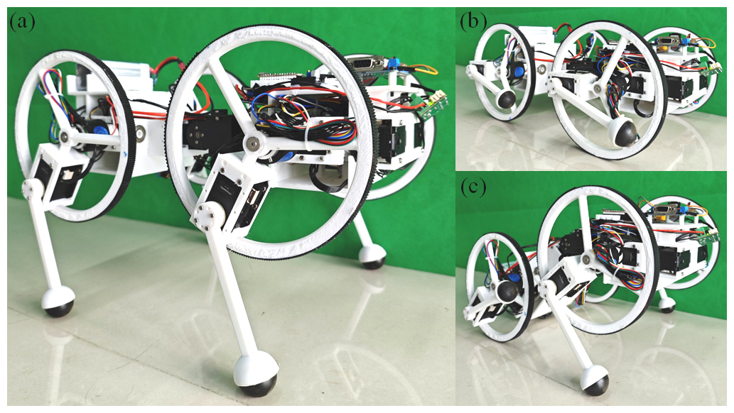
Table 1The existing typical transformable articulated-leg leg-wheel robots.
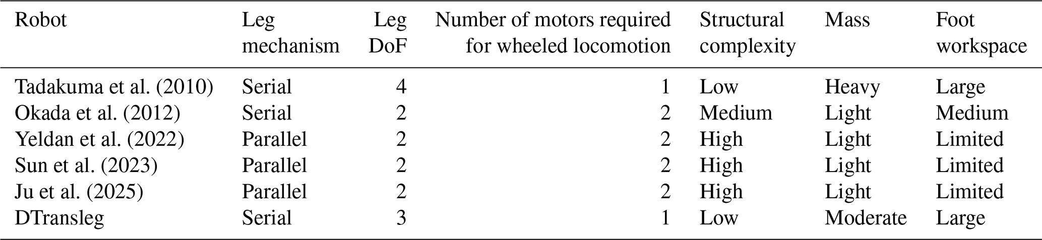
Furthermore, Peng et al. (2025) employ a sophisticated linkage and actuator suite to realize multiple locomotion modes – circular wheel, spoke wheel, and articulated leg – and can switch among them. To fully exploit the advantages of legged locomotion, this paper proposes DTransleg, a transformable leg-wheel quadruped designed with a serial articulated-leg architecture, as illustrated in Fig. 1. By reconfiguring the thigh link into a circular rim, DTransleg introduces wheeled motion without additional actuators or complex transmissions, yielding both a simpler structure and a more straightforward morphing process than comparable state-of-the-art platforms. A comparison between DTransleg and several typical leg-wheel robots with transformable leg-wheel mechanisms is presented in Table 1. Although the model of Okada et al. (2012) appears to be structurally similar, the underlying philosophy differs: PEOPLER-II embeds limited leg-like motion into a wheeled system, resulting in gaits that more closely resemble spoke-wheel locomotion. In contrast, DTransleg prioritizes full-fledged legged performance while opportunistically leveraging the thigh's circular geometry for wheeled travel. The technical contributions of this work are summarized below.
-
A structurally simple design method for a direct-drive leg-wheel robot is proposed, and its kinematic model is established.
-
The locomotion of the robot in three modes – four wheel, quadruped, and carriage mode – is planned, along with the transition methods between these modes.
-
Simulations and experiments are conducted to verify the feasibility of the proposed design method and motion planning.
The remainder of this paper is organized as follows. Section 2 introduces the robot design methodology. Section 3 establishes the robot kinematic model. Section 4 presents the motion planning for different locomotion modes and the switching strategies between modes. Section 5 uses simulations to verify the correctness of the kinematic model, motion planning, and the rationality of the mechanical design. Section 6 validates these aspects through experiments. Section 7 discusses the contributions of the robot by comparing it with existing transformable jointed leg-wheel robots. Finally, Sect. 8 concludes the paper.
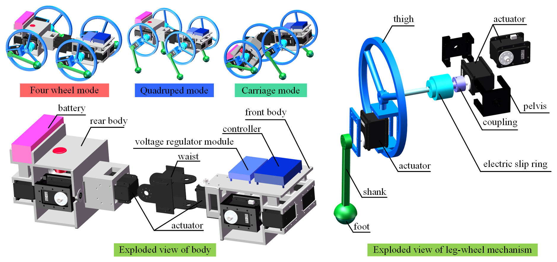
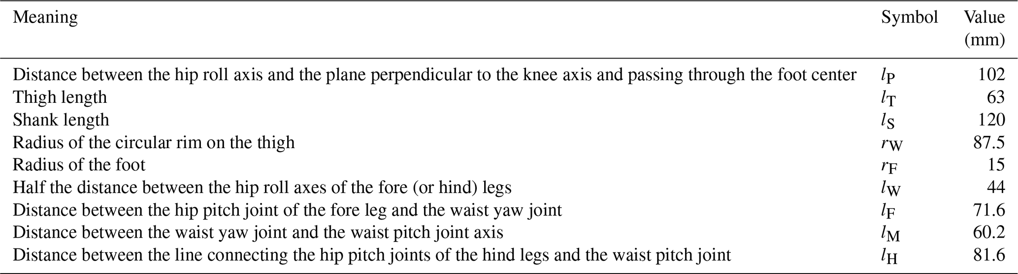
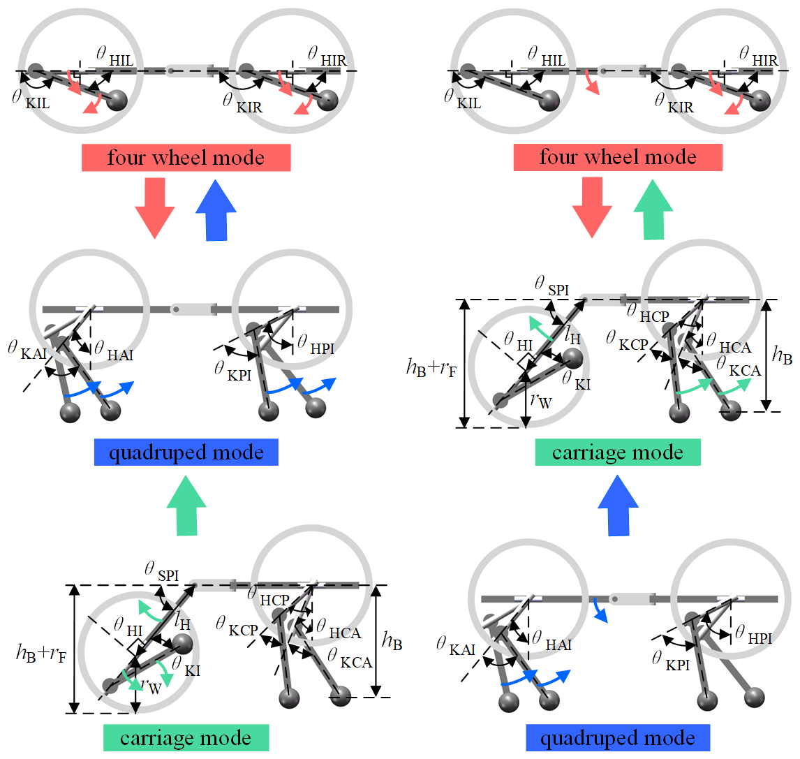
The 3D model of DTransleg is shown in Fig. 2, featuring three modes of locomotion: four-wheel mode, quadruped mode, and carriage mode. Comparing the three locomotion modes, the four-wheel mode achieves the highest motion efficiency and the strongest load capacity but has the weakest terrain adaptability. The quadruped mode has the lowest motion efficiency and the weakest load capacity but the strongest terrain adaptability. The carriage mode offers performance between the two. The robot body is divided into three parts: front body, waist, and rear body. The front body is connected to the waist by a yaw joint, and the rear body is connected to the waist by a pitch joint; the waist yaw joint and pitch joint are directly driven by servos. The introduction of the waist mechanism expands the leg workspace and enhances the flexibility of the robot's body, enabling more agile motion. In addition, waist joint rotation can adjust the robot's center of mass, thereby improving stability during locomotion (Wei et al., 2018, 2019). Four identical leg-wheel mechanisms are distributed on both sides of the robot body; these leg-wheel mechanisms have three direct-drive joints, including hip roll, hip pitch, and knee joints, with a simple structure. The pelvis, thigh, and shank are connected to the body in sequence through these three joints. Wheel locomotion is introduced by adding a circular rim onto the thigh and is driven by the servo that drives the hip pitch joint. The transition between wheel mode and leg mode only requires driving the knee joint to retract the shank into the circular rim of the thigh or to extend it out of the circular rim of the thigh. An electric slip ring is installed on the rotation axis of the thigh to solve the winding problem of the power and signal lines of the knee servo when the thigh rotates continuously. The hip roll joint can adjust the body height during wheel locomotion to keep the body level, thereby adapting to different terrains. The main parameters of DTransleg are listed in Table 2. Unlike the leg-wheel mechanism previously designed by Wei et al. (2024) that uses gears and synchronous belts to drive the joints, the leg-wheel mechanism of DTransleg adopts a direct-drive method, making the mechanism simpler.
3.1 Establishment of the D–H coordinate frames
Using the D–H method from Niku (2001), the kinematic model of the robot is established. The D–H coordinate frames are shown in Fig. 3. The origin of the base frame (frame 0) is located at the midpoint of the line connecting the intersections of the hip roll and hip pitch axes of the front leg mechanisms, the x axis points vertically upward from the body, and the z axis points in the forward direction of the robot. Table 3 gives the D–H parameters.
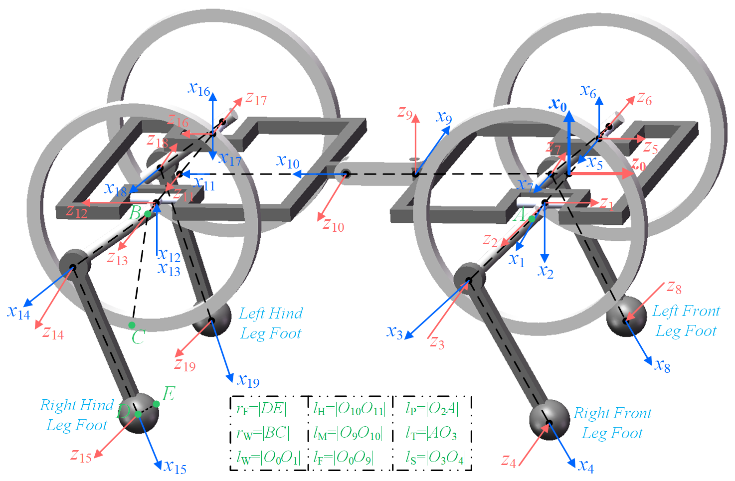
Table 3Main D–H parameters of DTransleg.
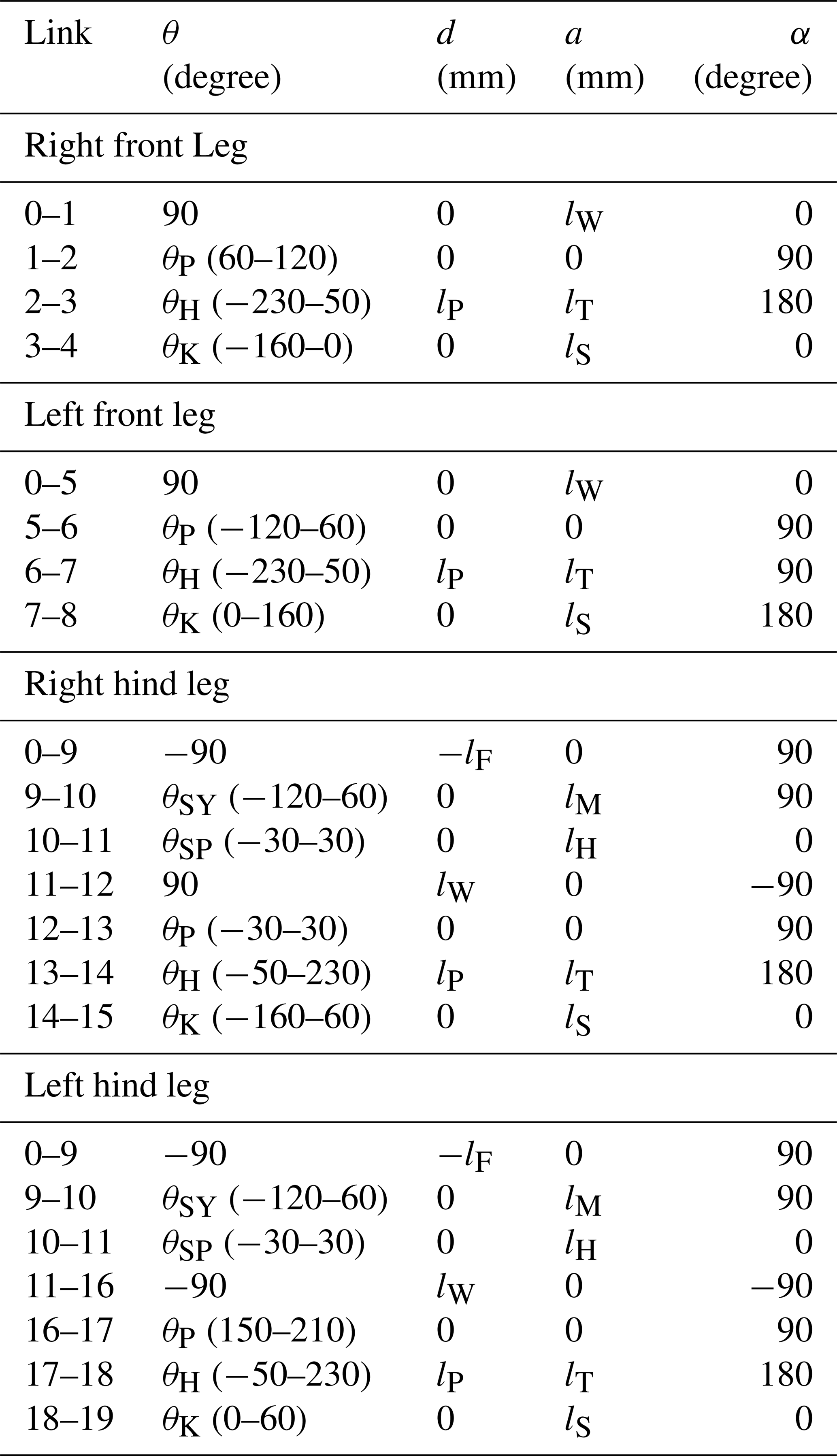
Note: θP, θH, θK, θSY, and θSP are the angles of the hip roll, hip pitch, knee, waist yaw, and waist pitch joints, respectively.
3.2 Forward kinematics
According to the parameters in Table 2, the x, y, and z coordinates of the leg foot ends are expressed in the base frame (frame 0) and are calculated using homogeneous transformation matrices. The position of the front leg foot end can be solved as follows:
where si denotes sin θi; ci denotes cos θi; and k1 is a coefficient, with 1 for the right front leg and −1 for the left front leg. The position of the rear-leg foot end is
where k2 is a coefficient: 1 for the right hind leg and −1 for the left hind leg.
3.3 Inverse kinematics
Given the foot end position (x, y, z), the inverse kinematics yield the joint angles of the front leg as
and the joint angles of the hind leg as
where n1, n2, n3, and n4 can be calculated as
4.1 Four-wheel mode
When the robot is in four-wheel motion, the servo driving the hip pitch joint operates in continuous rotation mode with velocity control; the velocity of four-wheel motion can be obtained from
where ωW is the angular velocity of the servo that drives the hip pitch joint.
4.2 Quadruped mode
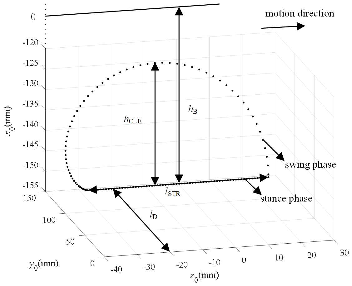
A time-based foot-end-trajectory-planning method is employed to realize quadruped locomotion; the foot end trajectory consists of a half-heart-shaped curve and a straight line, where the half-heart-shaped curve serves as the swing phase and is symmetric about the vertical line passing through the hip pitch joint center, while the straight line serves as the stance phase. Expressed with respect to coordinate system 0, the foot end trajectory is given as
where lSTR denotes the stride length, hCLE denotes the foot end lift height during the swing phase, hB denotes the body height, t denotes time, TL denotes the gait cycle, and TSW denotes the swing phase duration. k3 is a parameter indicating fore or hind legs, with 0 for fore and 1 for hind, and k4 indicates left or right legs, with 1 for right and −1 for left. When TL = 0.4 s, TSW = 0.2 s, lSTR = 55 mm, hCLE = 30 mm, hB = 155 mm, and lD = 146 mm, the foot end trajectory of the right foreleg is as shown in Fig. 4. In this paper, a trot gait is adopted for quadruped locomotion; thus, the speed of quadruped motion can be calculated as
4.3 Carriage mode
In the cart-like locomotion, the waist pitch joint rotates to maintain the front body horizontal. The front leg-wheel mechanisms perform legged locomotion, controlled by the foot end trajectory in Eq. (7), enabling uniform motion. The rear leg-wheel mechanisms perform wheeled locomotion, controlled by the angular velocity in Eq. (6). To ensure identical speeds for the front and rear leg-wheel mechanisms, the control parameters must satisfy
4.4 Transition from initial posture to different locomotion modes
The schematic diagram of the robot switching from the initial posture to different locomotion modes is shown in Fig. 5. In the initial posture, the body remains level and vertical, and the four legs are perpendicular to the body. With respect to the D–H coordinate system in Fig. 3, the waist yaw joint and pitch joint are set to −90 and 0°, respectively, and all of the joint angles of the leg-wheel mechanisms are 0°.
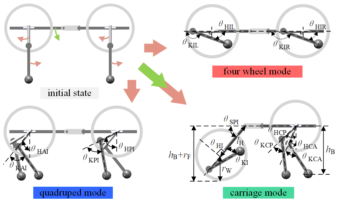
Figure 5Schematic diagram of the robot switching from the initial posture to different locomotion modes.
To switch from the initial posture to the four-wheel mode, the primary task is to retract the shank into the circular rim of the thigh. If only the knee joint is actuated to lift the shank, the robot's center of gravity (COG) shifts rearward, gradually moving away from the center of the support polygon and risking tip-over. Therefore, while lifting the shank, the thigh is simultaneously driven backward until it is parallel to the body, reducing COG displacement. The transition adopts joint space planning, driving each joint angle uniformly from the initial posture to the target posture, where θHIR, θHIL, θKIR, and θKIL are −90, 90, −160, and 160°, respectively.
To switch from the initial posture to the quadruped mode, the target posture is defined as the instant when all four legs simultaneously touch the ground – i.e., the transition point between stance and swing phases. Because the leg configuration changes only slightly, the COG variation is minimal; joint space planning is thus applied directly to move each leg joint from its initial position to the target position. The target angles θHAI, θKAI, θHPI, and θKPI are obtained by substituting the foot end positions into Eqs. (3) and (4).
To switch from the initial posture to the carriage mode, the front leg-wheel mechanisms must adopt the leg mode, the rear leg-wheel mechanisms must adopt the wheel mode, and the waist pitch joint must rotate to keep the front body horizontal. During retraction of the rear shank and rotation of the waist pitch joint, the rear foot ends move forward, tending to tip the robot backward. Therefore, the transition is divided into two steps. In step 1, the rear shank is lifted while the thigh is simultaneously driven backward to complete the rear-wheel-mode transition. In step 2, the waist pitch joint and the front leg joints are driven to their target positions. The rear joint angles θHI and θKI are identical to those in the four-wheel mode; the front joint angles θHCA, θKCA, θHCP, and θKCP are solved by substituting the foot end positions into Eqs. (3) and (4). The waist pitch joint angle is determined by
4.5 Mode transitions between different locomotion modes
The schematic diagram of transitions between different locomotion modes is shown in Fig. 6. From four-wheel mode to quadruped mode, the postures of all four leg-wheel mechanisms must be altered. To ensure a smooth transition, the four wheels are first synchronized, and the thighs are oriented backward, and then the thighs are driven downward while the shanks are lowered. During the transition, the robot's COG remains near the center of the support polygon so that a joint space planning method is directly applied to drive each joint to its target position. From four-wheel mode to carriage mode, only the postures of the front leg-wheel mechanisms and the waist pitch joint angle need to be changed. First, to minimize motion discrepancies among the front legs, the front leg wheels are synchronized with the thighs pointing backward. Subsequently, the waist pitch joint and the front leg-wheel joints are simultaneously driven to their target positions.
From quadruped mode to four-wheel mode, the four-wheel mode is inherently stable and does not require the thighs to be synchronized. Therefore, it suffices to retract the shanks into the circular rims of the thighs. From quadruped mode to carriage mode, the rear leg-wheel mechanisms must switch to wheel mode, and the hip pitch joints must rotate. Lifting the rear shanks and rotating the hip pitch joints both shift the robot's COG toward the rear of the support polygon. To ensure stability, the rear leg-wheels are first switched, after which the hip pitch joints are driven to their target positions. During the rear leg-wheel transition, lifting the shanks alone keeps the COG within the support polygon, and so the hip pitch joints remain unchanged.
From carriage mode to four-wheel mode, only the front leg-wheel mechanisms need to switch to wheel mode, and the waist pitch joint must rotate to align the front and rear bodies. Lifting the shanks of the front legs and rotating the waist pitch joint both enlarge the support polygon so that the transition is stable and each joint can be directly driven to its target position. From carriage mode to quadruped mode, only the rear leg-wheel mechanisms need to switch to leg mode, and the waist pitch joint must rotate to align the front and rear bodies. To ensure that the rear legs move in unison, the rear leg-wheel mechanisms are synchronized, and the thighs are oriented backward, keeping the rear boundary of the support polygon away from the robot's COG. Both the rear leg-wheel transition and the waist pitch joint rotation guarantee that the COG remains within the support polygon so that a joint space planning method is directly applied to drive each joint to its target position.
5.1 Simulation platform construction
The 3-D model created in SolidWorks is imported into CoppeliaSim, where rigid-body and joint parameters are configured to build the robot's dynamic model. Control code is written in MATLAB and co-simulated with CoppeliaSim. The Newton physics engine is selected in CoppeliaSim, and the time step in both MATLAB and CoppeliaSim is set to 0.01 s. The foot–ground contact is modeled using Coulomb friction, with the robot foot defined as rubber and the ground defined as ceramic tile. Accordingly, the static and dynamic friction coefficients are set to 0.8 and 0.6, respectively.
5.2 Sequential transition from initial state to four-wheel mode and then to quadruped mode
The entire motion process is divided into four stages: initial state to four-wheel mode, four-wheel locomotion, transition from four-wheel mode to quadruped mode, and quadruped locomotion. Simulation snapshots and the position–orientation variations during motion are shown in Fig. 7a. Position and orientation data are taken from the front body, with the positive z axis pointing vertically upward, the positive y axis pointing in the forward direction, and the positive x axis pointing to the robot's right. During 0–5 s, the robot transforms from the initial posture to wheel mode; body height decreases, and the robot moves slightly backward, while other data remain essentially unchanged, indicating a stable transformation. During 5–7 s, four-wheel locomotion is executed; displacement along the forward direction increases, while other data remain almost constant. Throughout four-wheel motion, the wheel speed is 0.5 rpm, yielding a theoretical velocity of 275 mm s−1 according to Eq. (6). Using forward-displacement data divided by elapsed time, the actual velocity is calculated to be approximately 259 mm s−1, slightly lower than the theoretical value due to a minor yaw deviation of about 1°. During 7–10 s, the robot transitions from four-wheel mode to quadruped mode; body height increases. Friction between the foot ends and the ground causes small variations in pitch, yaw, and roll angles. During 10–12 s, quadruped locomotion is performed with a gait period of 0.4 s, a stride length of 55 mm, a foot end trajectory height of 30 mm, and a body height of 155 mm. According to Eq. (8), the theoretical velocity is 275 mm s−1. During motion, forward displacement increases; pitch, yaw, and roll angles vary periodically with the gait cycle, and lateral displacement increases due to lack of balance control, causing oscillations and deviations. Using forward displacement divided by elapsed time, the actual velocity is approximately 229 mm s−1, which is lower than the theoretical value. This discrepancy is mainly attributed to the robot's yaw angle, as well as to contact impacts and local slipping occurring at the foot–ground interface.
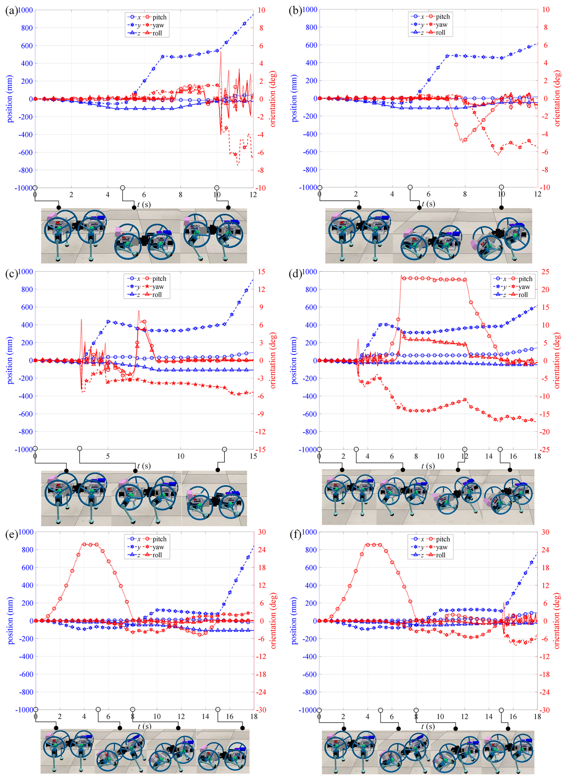
Figure 7Simulation snapshots and position–orientation curves of the front body: initial state to four-wheel mode and quadruped mode (a), initial state to four-wheel mode and carriage mode (b), initial state to quadruped mode and four-wheel mode (c), initial state to quadruped mode and carriage mode (d), initial state to carriage mode and four-wheel mode (e), and initial state to carriage mode and quadruped mode (f).
5.3 Sequential transition from initial state to four-wheel mode and then to carriage mode
The entire motion process is divided into four stages: initial state to four-wheel mode, four-wheel locomotion, transition from four-wheel mode to carriage mode, and carriage locomotion. Simulation snapshots and position–orientation variations are shown in Fig. 7b. The data for the first two stages are essentially the same as in Sect. 5.2. During 7–10 s, the robot transitions from four-wheel mode to carriage mode; the body rises, causing the pitch angle to change, but it returns to zero after adjustment of the waist pitch joint. Owing to inconsistent motion of the two front legs, the body experiences a 7° yaw change under foot–ground friction; roll angle also oscillates slightly but returns to zero after the transition. During 10–12 s, carriage locomotion is performed with a front leg gait period of 1 s, a stride length of 40 mm, a foot end trajectory height of 30 mm, and a body height of 135 mm. According to Eq. (9), the rear wheels are driven at 0.145 rpm; Eq. (8) gives a theoretical velocity of 80 mm s−1. Forward displacement increases; pitch, yaw, and roll angles exhibit slight periodic oscillations. Using forward displacement divided by elapsed time, the actual velocity is approximately 75 mm s−1, slightly lower than the theoretical value due to the robot's yaw deviation, together with contact impacts and local slipping during foot–ground interaction.
5.4 Sequential transition from initial state to quadruped mode and then to four-wheel mode
The entire motion process is divided into four stages: initial state to quadruped mode, quadruped locomotion, transition from quadruped mode to four-wheel mode, and four-wheel locomotion. Simulation snapshots and position–orientation variations are shown in Fig. 7c. During 0–3 s, the robot transitions from the initial posture to quadruped mode; the data remain almost unchanged, indicating a smooth transition. During 3–5 s, a trot gait is executed, and the simulation data are essentially the same as those in Sect. 5.2. During 5–13 s, the robot transitions from quadruped mode to four-wheel mode; the shanks are gradually retracted into the circular rims of the thighs, and body height decreases. Due to inconsistent motion among the leg-wheel mechanisms, foot–ground friction causes the body to deviate, and pitch and roll angles change; these angles return to zero after the transformation is completed. During 13–15 s, four-wheel locomotion is performed, and the overall data remain stable.
5.5 Sequential transition from initial state to quadruped mode and then to carriage mode
The entire motion process is divided into four stages: initial state to quadruped mode, quadruped locomotion, transition from quadruped mode to carriage mode, and carriage locomotion. Simulation snapshots and position–orientation variations are shown in Fig. 7d. The data for the first two stages are essentially the same as in Sect. 5.4. During 5–15 s, the robot transitions from quadruped mode to carriage mode. Before 6.8 s, the shanks of the leg-wheels are lifted off the ground, and the pitch angle increases to approximately 23°. Owing to inconsistent motion of the two rear shanks, foot–ground friction causes the body to deviate, and a roll angle appears. From 6.8 to 12 s, the shanks continue to retract into the circular rims of the thighs; no relative motion occurs between the robot and the ground, and so the data remain almost unchanged. From 12 to 15 s, the waist pitch joint rotates to the level of the front body, and the pitch and roll angles return to zero. During this adjustment, inconsistent motion of the two front legs induces a slight body deviation. From 15 to 18 s, the robot performs carriage locomotion, producing significant forward displacement and a small lateral displacement due to the yaw angle.
5.6 Sequential transition from initial state to carriage mode and then to four-wheel mode
The entire motion process is divided into four stages: initial state to carriage mode, carriage locomotion, transition from carriage mode to four-wheel mode, and four-wheel locomotion. Simulation snapshots and position–orientation variations are shown in Fig. 7e. During 0–8 s, the robot transitions from the initial posture to carriage mode. Before 5 s, the rear thighs move backward, and the shanks gradually retract into the circular rims of the thighs, and the body pitch angle increases. At approximately 4 s, the shanks lift off the ground; thereafter, body height and pitch angle remain unchanged, but body translation occurs due to thigh rotation. From 5 to 8 s, the waist pitch joint rotates while the front legs adjust posture, gradually leveling the front body. From 8 to 10 s, the robot performs carriage locomotion, and the data remain stable. From 10 to 15 s, the robot transitions from carriage mode to four-wheel mode. Body height decreases, and the pitch angle changes but returns to zero upon completion of the transition. Inconsistent motion of the two front legs causes body deviation under ground friction, and the roll angle varies, but it also returns to zero when the transition is completed. From 15 to 18 s, the robot performs four-wheel locomotion, and the motion is stable.
5.7 Sequential transition from initial state to carriage mode and then to quadruped mode
The entire motion process is divided into four stages: initial state to carriage mode, carriage locomotion, transition from carriage mode to quadruped mode, and quadruped locomotion. Simulation snapshots and position–orientation variations are shown in Fig. 7f. The data for the first two stages are essentially the same as in Sect. 5.6. During 10–15 s, the robot transitions from carriage mode to quadruped mode. During the transition, the pitch angle first increases due to rotation of the waist pitch joint and then decreases as the rear leg postures are adjusted, finally returning to zero when the body is level. Inconsistent motion of the two rear legs causes body deviation under foot–ground friction. From 15 to 18 s, the robot performs a trot gait, and the simulation data are similar to those in Sect. 4.2.
6.1 Prototype preparation
The robot employs an STM32 development board as its controller and MX-28 servos as actuators; the servos offer a rated torque of 3.1 N m. A 14.8 V RC battery supplies power to both the servos and the STM32 board; the board itself is powered through a 5 V regulator module. The shank servos are connected to the body servos via an electrical slip ring, allowing the thighs to rotate without limit. All mechanical parts are 3-D-printed in PLA (polylactic acid). The complete robot weighs 3.35 kg. In the experiments, the robot's position and posture are measured using video-based motion tracking. Feature points are marked on the robot body and tracked using high-precision image processing software to ensure measurement accuracy and consistency. Due to the limitations of video-based measurement, only the front body height and pitch angle – being the most relevant posture indicators – are analyzed and presented.
6.2 Sequential transition from initial state to four-wheel mode and then to quadruped mode
The entire motion sequence matches Sect. 5.2 except for differences in timing and parameters. Experimental snapshots and the corresponding variations in body height and pitch angle are shown in Fig. 8a. The trends of front body height and pitch angle during the experiment agree well with the simulation. When transitioning from the initial posture to the four-wheel mode, body height decreases; during wheeled motion, body height remains essentially constant, and the pitch angle is stable. Throughout the four wheel phase, wheels rotate at 0.2 rpm, yielding a theoretical velocity of 110 mm s−1 via Eq. (6). The measured actual velocity is approximately 107 mm s−1, matching the theory. When switching from four-wheel to quadruped mode, body height rises, and the pitch angle oscillates due to inconsistent motion among the four leg-wheel mechanisms. In the quadruped phase, the gait period is set to 1.049 s, stride length is set to 55 mm, foot end lift height is set to 30 mm, and body height is set to 155 mm; Eq. (8) predicts a theoretical velocity of 105 mm s−1, whereas the actual velocity is 65 mm s−1, which is significantly lower. This discrepancy is attributed to the lack of balance control: pitch angle and body height vary cyclically with the gait period, and leg dragging occurs.
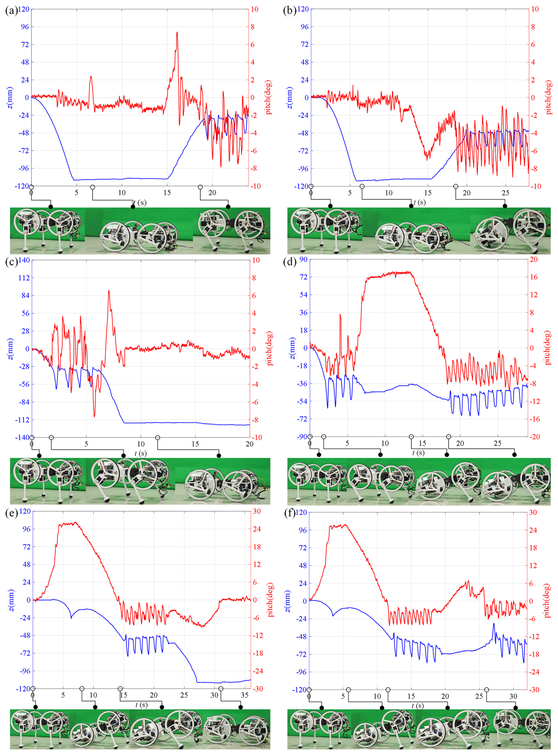
Figure 8Experimental snapshots and curves of front body height and pitch angle: initial state to four-wheel mode and quadruped mode (a), initial state to four-wheel mode and carriage mode (b), initial state to quadruped mode and four-wheel mode (c), initial state to quadruped mode and carriage mode (d), initial state to carriage mode and four-wheel mode (e), and initial state to carriage mode and quadruped mode (f).
6.3 Sequential transition from initial state to four-wheel mode and then to carriage mode
The entire motion sequence matches Sect. 5.3 except for differences in timing and parameters. Experimental snapshots and the corresponding variations in body height and pitch angle are shown in Fig. 8b. The trends of front body height and pitch angle during the experiment agree well with the simulation; the first two stages coincide with Sect. 5.2. When switching from the four-wheel mode to the carriage mode, the body height rises. Owing to foot–ground friction and joint-level assembly errors, the body does not reach the desired posture. Specifically, mechanical play at the joints caused by assembly tolerances allows slight leg linkage motion even when the servos are not actuated, which leads to posture deviations. During carriage locomotion, pitch angle and body height vary cyclically with the gait period. Carriage parameters are set as follows: the front leg gait period is 1.14 s, stride length is 40 mm, foot end lift height is 30 mm, and body height is 135 mm. Eq. (9) gives a rear-wheel speed of 0.127 rpm, and Eq. (8) predicts a theoretical velocity of 70 mm s−1. The measured actual velocity is 69 mm s−1, which is consistent with the theory.
6.4 Sequential transition from initial state to quadruped mode and then to four-wheel mode
The entire motion sequence matches Sect. 5.4 except for differences in timing and parameters. Experimental snapshots and the corresponding variations in body height and pitch angle are shown in Fig. 8c. Results show that the transition from the initial posture to quadruped mode is stable. When switching from quadruped to four-wheel mode, inconsistent motion among the four leg-wheel mechanisms causes oscillations, yet the transition is completed successfully. The trends of front body height and pitch angle during the experiment match the simulation, but the amplitude of variation is slightly larger owing to structural errors present in hardware but absent in simulation.
6.5 Sequential transition from initial state to quadruped mode and then to carriage mode
The entire motion sequence matches Sect. 5.5 except for differences in timing and parameters. Experimental snapshots and the corresponding variations in body height and pitch angle are shown in Fig. 8d. Results show that the first two stages coincide with Sect. 5.4. Moreover, the robot transitions smoothly from quadruped mode to carriage mode. The changes in front body height and pitch angle during the experiment agree well with the dynamic simulation, but the amplitude of variation is slightly larger because structural errors present in hardware are not modeled in the simulation.
6.6 Sequential transition from initial state to carriage mode and then to four-wheel mode
The entire motion sequence matches Sect. 5.6 except for differences in timing and parameters. Experimental snapshots and the corresponding variations in body height and pitch angle are shown in Fig. 8e. The trends of front body height and pitch angle during the experiment agree well with the simulation. Results show that the transitions from initial posture to carriage mode and from carriage mode to four-wheel mode are stable, although minor pitch angle oscillations occur.
6.7 Sequential transition from initial state to carriage mode and then to quadruped mode
The entire motion sequence matches Sect. 5.7 except for differences in timing and parameters. Experimental snapshots and the corresponding variations in body height and pitch angle are shown in Fig. 8f. The trends of front body height and pitch angle during the experiment agree well with the simulation. Results show that the first two stages coincide with Sect. 6.6. Moreover, the robot transitions smoothly from carriage mode to quadruped mode.
This paper presents the design and validation of a transformable articulated-leg leg-wheel robot named DTransleg, aiming to address the structural complexity and complicated morphing mechanisms commonly observed in existing articulated leg-wheel robots. The robot is driven by four identical leg-wheel mechanisms capable of switching between wheel mode and articulated-leg mode. By designing the thigh segment as a circular rim, wheeled locomotion is directly integrated into the leg structure without introducing additional actuators, resulting in a compact and mechanically simple configuration. In leg mode, each mechanism provides three active joints to ensure sufficient mobility, while, in wheel mode, active motion is achieved using the hip pitch actuator. In addition, waist yaw and pitch joints are incorporated to enhance motion flexibility and stability. The design methodology, kinematic modeling, motion planning for multiple locomotion modes, and transition strategies are systematically developed and validated through both simulations and physical experiments.
Several representative transformable leg-wheel robots have been reported in the literature. Tadakuma et al. (2010) proposed a robot whose serial leg links reconfigure into a complete circular wheel through coordinated joint motions. Although the mechanism is conceptually simple and supports both wheeled and legged locomotion, as well as mode transitions, the leg-wheel modules are relatively heavy, which limits agility and efficiency. Okada et al. (2012) realized transformation by extending and retracting the shank within a circular thigh segment, resulting in a lighter leg-wheel module; however, the mechanism is structurally complex and exhibits limited flexibility, and experimental validation was mainly restricted to wheeled and spoke-like locomotion. Parallel-leg-based approaches have also been explored. Yeldan et al. (2022) and Sun et al. (2023) employed four-bar linkages with arc-shaped links, allowing the legs to morph into pseudo-wheels or semicircular shapes. To place all actuators on the body, these designs inevitably increased mechanical complexity. While Yeldan et al. (2022) demonstrated both legged and wheeled locomotion, Sun et al. (2023) additionally implemented RHex-like legged locomotion. More recently, Ju et al. (2025) introduced an origami-inspired fan mechanism into a four-bar linkage to achieve transformation between circular wheels and parallel legs; however, this approach further increased structural complexity.
Compared with the above designs, DTransleg achieves a favorable balance between mechanism simplicity, locomotion versatility, and transformation efficiency. The integration of the wheel function into the thigh segment eliminates additional transformation actuators and complex morphing linkages, significantly simplifying the mechanical structure. Meanwhile, the articulated-leg configuration provides sufficient degrees of freedom for stable legged locomotion, obstacle crossing, and posture adjustment. Multiple locomotion modes – including four-wheel, quadruped, and carriage modes – are realized using a unified mechanism and a straightforward transformation strategy. These characteristics make the proposed robot well suited for practical applications that require adaptability to diverse terrains while maintaining a compact, lightweight, and robust mechanical design.
This paper presents the design and development of a transformable articulated-leg leg-wheel robot named DTransleg. By introducing a circular rim at the thigh, wheeled locomotion is integrated into the leg structure, enabling a compact mechanical design and a straightforward transformation mechanism. Simulations and experiments demonstrate that the robot can achieve stable four-wheel, quadruped, and carriage locomotion, as well as smooth and reliable transitions among these modes.
Despite these promising results, the current prototype still requires further optimization in mechanical structure and control strategies to fully exploit its potential performance. Joint stiffness, assembly precision, and control robustness should be improved to reduce posture deviations and to enhance motion consistency. In terms of terrain adaptability, the robot is expected to achieve high-speed and energy-efficient wheeled locomotion on flat terrain; stable legged locomotion on rough terrain with strong obstacle-crossing capability; and load-bearing, obstacle-crossing, and self-recovery performance in carriage mode. Future work will focus on implementing a closed-loop control strategy to further improve dynamic stability and motion performance, as well as to investigate the role of the waist joints and to integrate additional sensors to enhance motion flexibility, stability, environmental perception, and locomotion autonomy.
No data sets were used in this article.
Simulation and experimental videos can be found on the following website: https://www.youtube.com/watch?v=9bXc_vzmvwI (last access: 16 January 2026).
Methodology: ZW. Hardware: JLG. Software: JWZ. Investigation: YY, SX, and WXW. Writing (original draft preparation): JWZ and JYR. Writing (review and editing): JL and AGS. Paper revision: JLG. All of the authors read and agreed to the published version of the paper.
The contact author has declared that none of the authors has any competing interests.
Publisher's note: Copernicus Publications remains neutral with regard to jurisdictional claims made in the text, published maps, institutional affiliations, or any other geographical representation in this paper. The authors bear the ultimate responsibility for providing appropriate place names. Views expressed in the text are those of the authors and do not necessarily reflect the views of the publisher.
This research was funded in part by the National Natural Science Foundation of China under grant no. 62103197 and in part by the Postgraduate Research & Practice Innovation Program of Jiangsu Province under grant no. SJCX25_0533.
This research has been supported by the National Natural Science Foundation of China (grant no. 62103197) and the Postgraduate Research & Practice Innovation Program of Jiangsu Province (grant no. SJCX25_0533).
This paper was edited by Pengyuan Zhao and reviewed by two anonymous referees.
Bai, L., Guan, J., Chen, X., Hou, J., and Duan, W.: An optional passive/active transformable wheel-legged mobility concept for search and rescue robots, Robotics and Autonomous Systems, 107, 145–155, https://doi.org/10.1016/j.robot.2018.06.005, 2018.
Bishop, T., Ye, K., and Karydis, K.: Design and central pattern generator control of a new transformable wheel-legged robot, 2024 IEEE International Conference on Robotics and Automation (ICRA), Yokohama, Japan, 13–17 May 2024, 11383–11389, https://doi.org/10.1109/ICRA57147.2024.10610884, 2024.
Blake, J. J. and Hong, D.: IMPASS: Intelligent mobility platform with active spoke system, 2009 IEEE International Conference on Robotics and Automation, Kobe, Japan, 12–17 May 2009, 1605–1606, https://doi.org/10.1109/ROBOT.2009.5152735, 2009.
Cao, R., Gu, J., Yu, C., and Rosendo, A.: Omniwheg: An omnidirectional wheel-leg transformable robot, 2022 IEEE/RSJ International Conference on Intelligent Robots and Systems (IROS), Kyoto, Japan, 23–27 October 2022, 5626–5631, https://doi.org/10.1109/IROS47612.2022.9982030, 2022.
Chen, J., Xu, K., and Ding, X.: Roller-skating of mammalian quadrupedal robot with passive wheels inspired by human, IEEE/ASME Transactions on Mechatronics, 26, 1624–1634, https://doi.org/10.1109/TMECH.2020.3025942, 2021.
Chen, J., Qin, R., Huang, L., He, Z., Xu, K., and Ding, X.: Unlocking Versatile Locomotion: A Novel Quadrupedal Robot with 4-DoFs Legs for Roller Skating, 2024 IEEE International Conference on Robotics and Automation (ICRA), Yokohama, Japan, 13–17 May 2024, 8037–8043, https://doi.org/10.1109/ICRA57147.2024.10610706, 2024a.
Chen, S. C., Huang, K. J., Chen, W. H., Shen, S. Y., Li, C. H., and Lin, P. C.: Quattroped: a leg-wheel transformable robot, IEEE/ASME Transactions On Mechatronics, 19, 730–742, https://doi.org/10.1109/TMECH.2013.2253615, 2014.
Chen, Z. R., Yu, W. S., and Lin, P. C.: Fast Wheeled Driving to Legged Leaping onto a Step in a Leg-Wheel Transformable Robot, 2024 IEEE International Conference on Robotics and Automation (ICRA), Yokohama, Japan, 13–17 May 2024, 11342–11348, https://doi.org/10.1109/ICRA57147.2024.10610303, 2024b.
Clark, A. J., Cissell, K. A., and Moore, J. M.: Evolving controllers for a transformable wheel mobile robot, Complexity, 2018, 7692042, https://doi.org/10.1155/2018/7692042, 2018.
Deng, Y., Hua, Y., Napp, N., and Petersen, K.: A compiler for scalable construction by the Termes robot collective, Robotics and Autonomous Systems, 121, 103240, https://doi.org/10.1016/j.robot.2019.07.010, 2019.
Du, W., Fnadi, M., and Benamar, F.: A new whole-body motion generator and adaptive altitude control for a quadruped-on-wheel robot, Journal of Mechanisms and Robotics, 15, 041005, https://doi.org/10.1115/1.4055060, 2023.
Endo, G. and Hirose, S.: Study on roller-walker – improvement of locomotive efficiency of quadruped robots by passive wheels, Advanced Robotics, 26, 969–988, https://doi.org/10.1163/156855312X633066, 2012.
Fu, Z., Xu, H., Li, Y., and Guo, W.: Design of a novel wheel-legged robot with rim shape changeable wheels, Chinese Journal of Mechanical Engineering, 36, 153, https://doi.org/10.1186/s10033-023-00974-7, 2023.
Ge, Y., Gao, F., and Chen, W.: A transformable wheel-spoke-paddle hybrid amphibious robot, Robotica, 42, 701–727, https://doi.org/10.1017/S0263574723001716, 2024.
Godden, T., Mulvey, B. W., Redgrave, E., and Nanayakkara, T.: PaTS-Wheel: A passively-transformable single-part wheel for mobile robot navigation on unstructured terrain, IEEE Robotics and Automation Letters, 9, 5512–5519, https://doi.org/10.1109/LRA.2024.3389828, 2024.
He, J., Sun, Y., Yang, L., Sun, J., Xing, Y., and Gao, F.: Design and control of TAWL – a wheel-legged rover with terrain-adaptive wheel speed allocation capability, IEEE/ASME Transactions on Mechatronics, 27, 2212–2223, https://doi.org/10.1109/TMECH.2022.3176638, 2022.
Huang, P. C., Chang, I. C., Yu, W. S., and Lin, P. C.: Body Velocity Estimation in a Leg–Wheel Transformable Robot without A Priori Knowledge of Leg–Wheel Ground Contacts, 2024 IEEE International Conference on Robotics and Automation (ICRA), Yokohama, Japan, 13–17 May 2024, 11349–11355, https://doi.org/10.1109/ICRA57147.2024.10610114, 2024.
Itabashi, K. and Kumagai, M.: Development of a human type legged robot with roller skates, 2010 IEEE/SICE International Symposium on System Integration, Sendai, Japan, 21–22 December 2010, 120–125, https://doi.org/10.1109/SII.2010.5708312, 2010.
Iverach-Brereton, C., Baltes, J., Anderson, J., Winton, A., and Carrier, D.: Gait design for an ice skating humanoid robot, Robotics and Autonomous Systems, 62, 306–318, https://doi.org/10.1016/j.robot.2013.09.016, 2014.
Ju, Z., Wei, K., and Xu, Y.: From Concept to Field Trials: Design, Analysis, and Evaluation of a Novel Quadruped Robot With Deformable Wheel-Foot Structure, IEEE Transactions on Robotics, 41, 3143–3161, https://doi.org/10.1109/TRO.2025.3562449, 2025.
Jung, T., Lim, J., Bae, H., Lee, K., Joe, H., and Oh, J.: Development of the humanoid disaster response platform DRC-HUBO+, IEEE Transactions on Robotics, 34, 1–17, https://doi.org/10.1109/TRO.2017.2776287, 2018.
Karumanchi, S., Edelberg, K., Baldwin, I., Nash, J., Reid, J., Bergh, C., Leichty, J., Carpenter, K., Shekels, M., Gildner, M., Newill-Smith, D., Carlton, J., Koehler, J., Dobreva, T., Frost, M., Hebert, P., Borders, J., Ma, J., Douillard, B., Backes, P., Kennedy, B., Satzinger, B., Lau, C., Byl, K., Shankar, K., and Burdick, J.: Team RoboSimian: semi-autonomous mobile manipulation at the 2015 DARPA robotics challenge finals, Journal of Field Robotics, 34, 305–332, https://doi.org/10.1002/rob.21676, 2017.
Kim, Y., Lee, Y., Lee, S., Kim, J., Kim, H., and Seo, T.: STEP: A new mobile platform with 2-DOF transformable wheels for service robots, IEEE/ASME Transactions On Mechatronics, 25, 1859–1868, https://doi.org/10.1109/TMECH.2020.2992280, 2020.
Kim, Y. S., Jung, G. P., Kim, H., Cho, K., and Chu, C.: Wheel transformer: A wheel-leg hybrid robot with passive transformable wheels, IEEE Transactions on Robotics, 30, 1487–1498, https://doi.org/10.1109/TRO.2014.2365651, 2014.
Kwon, Y., Seo, H., Ryu, S., Lim, K., Pi, Y., and Seo, T.: NoteBot: Fully retractable spoke-wheel robot based on a compliant mechanism, Sensors and Actuators A: Physical, 397, 117173, https://doi.org/10.1016/j.sna.2025.117173, 2025.
Lacagnina, M., Muscato, G., and Sinatra, R.: Kinematics, dynamics and control of a hybrid robot Wheeleg, Robotics and Autonomous Systems, 45, 161–180, https://doi.org/10.1016/j.robot.2003.09.006, 2003.
Lee, D. Y., Kim, S. R., Kim, J. S., Park, J. J., and Cho, K. J.: Origami wheel transformer: A variable-diameter wheel drive robot using an origami structure, Soft Robotics, 4, 163–180, https://doi.org/10.1089/soro.2016.0038, 2017.
Lee, J., Bjelonic, M., Reske, A., Wellhausen, L., Miki, T., and Hutter, M.: Learning robust autonomous navigation and locomotion for wheeled-legged robots, Science Robotics, 9, 9641, https://doi.org/10.1126/scirobotics.adi9641, 2024.
Lee, Y., Ryu, S., Won, J. H., Kim, S., Kim, H. S., and Seo, T.: Modular two-degree-of-freedom transformable wheels capable of overcoming obstacle, IEEE Robotics and Automation Letters, 7, 914–920, https://doi.org/10.1109/LRA.2021.3096223, 2021.
Li, M., Guo, S., Hirata, H., and Ishihara, H.: A roller-skating/walking mode-based amphibious robot, Robotics and Computer-Integrated Manufacturing, 44, 17–29, https://doi.org/10.1016/j.rcim.2016.06.005, 2017.
Li, Y., Wei, Z., Guo, J., Ren, J., Ding, Y., Wang, W., Liu, J., and Song, A.: A Stair-Climbing Wheelchair with Novel Spoke Wheels for Smooth Motion, Applied Sciences, 15, 5433, https://doi.org/10.3390/app15105433, 2025.
Liu, J., Zhao, D., Liu, C., and Xing, J.: Reconfiguration motion analysis and motion quality control of an unmanned metamorphic vehicle, Control Engineering Practice, 142, 105776, https://doi.org/10.1016/j.conengprac.2023.105776, 2024.
Luces, J. V., Matsuzaki, S., and Hirata, Y.: RoVaLL: Design and development of a multi-terrain towed robot with variable lug-length wheels, IEEE Robotics and Automation Letters, 5, 6017–6024, https://doi.org/10.1109/LRA.2020.3010495, 2020.
Mertyüz, İ., Tanyıldızı, A. K., Taşar, B., Tatar, A., and Yakut, O.: FUHAR: A transformable wheel-legged hybrid mobile robot, Robotics and Autonomous Systems, 133, 103627, https://doi.org/10.1016/j.robot.2020.103627, 2020.
Murphy, D., Giuliani, M., and Bremner, P.: Evaluation and Design Recommendations for a Folding Morphing-wheg Robot for Nuclear Characterisation, 2024 IEEE/RSJ International Conference on Intelligent Robots and Systems (IROS), Abu Dhabi, United Arab Emirates, 14–18 October 2024, 9088–9093, https://doi.org/10.1109/IROS58592.2024.10802195, 2024.
Namgung, J. and Cho, B. K.: Legway: Design and Development of a Transformable Wheel-Leg Hybrid robot, 2023 IEEE-RAS 22nd International Conference on Humanoid Robots (Humanoids), Austin, TX, USA, 12–14 December 2023, 1–8, https://doi.org/10.1109/Humanoids57100.2023.10375169, 2023.
Niku, S. B.: Introduction to robotics: analysis, systems, applications, Prentice Hall, New Jersey, 349 pp., ISBN 0130613096, 2001.
Okada, T., Mahmoud, A., Botelho, W. T., and Shimizu, T.: Trajectory estimation of a skid-steering mobile robot propelled by independently driven wheels, Robotica, 30, 123–132, https://doi.org/10.1017/S026357471100035X, 2012.
Ottaviano, E. and Rea, P.: Design and operation of a 2-DOF leg-wheel hybrid robot, Robotica, 31, 1319–1325, https://doi.org/10.1017/S0263574713000556, 2013.
Pan, L. H., Kuo, C. N., Huang, C. Y., and Chou, J.: The Claw-Wheel transformable hybrid robot with reliable stair climbing and high maneuverability, 2016 IEEE International Conference on Automation Science and Engineering (CASE), Fort Worth, TX, USA, 21–25 August 2016, 233–238, https://doi.org/10.1109/COASE.2016.7743386, 2016.
Peng, Y., Pan, Y., Shan, M., Zhou, S., Lin, C., and Gao, F.: TWLHex: A Biologically Inspired Multi-Morphology Transformable Wheel-Legged Hexapod, IEEE Robotics and Automation Letters, 10, 6656–6663, https://doi.org/10.1109/LRA.2025.3569121, 2025.
Polzin, M., Guan, Q., and Hughes, J.: Robotic locomotion through active and passive morphological adaptation in extreme outdoor environments, Science Robotics, 10, 6419, https://doi.org/10.1126/scirobotics.adp6419, 2025.
Raghavan, V., S., Kanoulas, D., Caldwell, D., G., and Tsagarakis, N.: Reconfigurable and agile legged-wheeled robot navigation in cluttered environments with movable obstacles, IEEE Access, 10, 2429–2445, https://doi.org/10.1109/ACCESS.2021.3139438, 2021.
Ryu, S., Lee, Y., and Seo, T. W.: Shape-morphing wheel design and analysis for step climbing in high speed locomotion, IEEE Robotics and Automation Letters, 5, 1977–1982, https://doi.org/10.1109/LRA.2020.2970977, 2020.
She, Y., Hurd, C. J., and Su, H. J.: A transformable wheel robot with a passive leg, 2015 IEEE/RSJ international conference on intelligent robots and systems (IROS), Hamburg, Germany, 28 September–2 October 2015, 4165–4170, https://doi.org/10.1109/IROS.2015.7353966, 2015.
Shen, Y., Zhang, G., Tian, Y., and Ma, S.: Development of a wheel-paddle integrated quadruped robot for rough terrain and its verification on hybrid mode, IEEE Robotics and Automation Letters, 3, 4062–4067, https://doi.org/10.1109/LRA.2018.2862431, 2018.
Shi, K., Jiang, Z., Liu, B., Yang, G., and Jin, M.: Synergistic Terrain-Adaptive Morphing and Trajectory Tracking in a Transformable-Wheeled Robot, IEEE Robotics and Automation Letters, 10, 1656–1663, https://doi.org/10.1109/LRA.2024.3524876, 2025.
Siboni, T., Coronel, M., and Zarrouk, D.: Design and Modeling of a Reconfigurable Robot: Decoupled STAR (DSTAR), IEEE Robotics and Automation Letters, 11, 882–889, https://doi.org/10.1109/LRA.2025.3634888, 2026.
Sonsalla, R. U., Planthaber, S., Dominguez, R., Dettmann, A., Cordes, F., Huelsen, B., Schulz, C., Schoeberl, P., Kasperski, S., Wiedemann, H., and Kirchner F.: Towards a semi-autonomous robotic exploration of a lunar skylight cavity, 2022 IEEE Aerospace Conference (AERO), Big Sky, MT, USA, 5–12 March 2022, 1–20, https://doi.org/10.1109/AERO53065.2022.9843610, 2022.
Sun, C., Yang, G., Yao, S., Liu, Q., Wang, J., and Xiao, X.: RHex-T3: A transformable hexapod robot with ladder climbing function, IEEE/ASME Transactions On Mechatronics, 28, 1939–1947, https://doi.org/10.1109/TMECH.2023.3276756, 2023.
Sun, T., Xiang, X., Su, W., Wu, H., and Song, Y.: A transformable wheel-legged mobile robot: Design, analysis and experiment, Robotics and Autonomous Systems, 98, 30–41, https://doi.org/10.1016/j.robot.2017.09.008, 2017.
Sun, Y., Zhang, L., Wang, M., Ding, J., Jia, W., and Pu, H.: Design and experimental evaluation of a multi-mode mobile robot based on eccentric paddle mechanism, IEEE Robotics and Automation Letters, 6, 8607–8614, https://doi.org/10.1109/LRA.2021.3112757, 2021.
Tadakuma, K., Tadakuma, R., Maruyama, A., Rohmer, E., Nagatani, K., and Yoshida K.: Mechanical design of the wheel-leg hybrid mobile robot to realize a large wheel diameter, 2010 IEEE/RSJ international conference on intelligent robots and systems, Taipei, Taiwan, 18–22 October 2010, 3358–3365, https://doi.org/10.1109/IROS.2010.5651912, 2010.
Wang, T. H. and Lin, P. C.: A reduced-order-model-based motion selection strategy in a leg-wheel transformable robot, IEEE/ASME Transactions on Mechatronics, 27, 3315–3321, https://doi.org/10.1109/TMECH.2021.3126606, 2022.
Wei, Y. and Lee, K.: CLAW: Cycloidal Legs-Augmented Wheels for Stair and Obstacle Climbing in Mobile Robots, IEEE/ASME Transactions on Mechatronics, 30, 1536–1546, https://doi.org/10.1109/TMECH.2024.3435767, 2025.
Wei, Z., Song, G., Sun, H., Qi, Q., Gao, Y., and Qiao, G.: Turning strategies for the bounding quadruped robot with an active spine, Industrial Robot: An International Journal, 45, 657–668, https://doi.org/10.1108/IR-06-2018-0119, 2018.
Wei, Z., Song, G., Sun, H., Qiao, G., Qi, Q., He, M., and Song, A.: Kinematic modeling and trotting gait planning for the quadruped robot with an active spine, Journal of Southeast University (Natural Science Edition), 49, 1019–1025, https://doi.org/10.3969/j.issn.1001-0505.2019.06.001, 2019 (in Chinese with English abstract).
Wei, Z., Ping, P., Luo, Y., Liu, J., Chen, D., Wang, W., Sun, H., Song, A., and Song, G.: A novel transformable leg-wheel mechanism, Journal of Mechanisms and Robotics, 16, 031008, https://doi.org/10.1115/1.4057069, 2024.
Wei, Z., Cai, Z., Yu, Z., Xiang, S., Yang, Y., Liu, J., Song, G., and Song, A.: BiTSpoke: A Leg-Wheel Robot with Single-Motor Driven Actively-Transformable Spoke Wheels, IEEE Robotics and Automation Letters, 10, 4874–4881, https://doi.org/10.1109/LRA.2025.3554383, 2025a.
Wei, Z., Ren, J., Guo, J., Yang, Y., Xiang, S., Chen, D., Liu, J., and Song, A.: SlidBot: A Quadruped Robot with Passive Wheels for Roller Skating, Journal of Bionic Engineering, 22, 2831–2848, https://doi.org/10.1007/s42235-025-00770-0, 2025b.
Wei, Z., Yu, Z., Cai, Z., Chen, D., Wang, W., Tian, R., Liu, J., and Sun, H.: BiDSpoke: A Leg-Wheel Robot With Bidirectionally Transformable and Isotropic Spoke Wheels, IEEE/ASME Transactions on Mechatronics, https://doi.org/10.1109/TMECH.2025.3614873, 2025c.
Xu, K. and Ding, X.: Typical gait analysis of a six-legged robot in the context of metamorphic mechanism theory, Chinese Journal of Mechanical Engineering, 26, 771–783, https://doi.org/10.3901/CJME.2013.04.771, 2013.
Xu, K., Wang, S., Wang, J., Wang, X., Chen, Z., and Si, J.: High-adaption locomotion with stable robot body for planetary exploration robot carrying potential instruments on unstructured terrain, Chinese Journal of Aeronautics, 34, 652–665, https://doi.org/10.1016/j.cja.2020.11.012, 2021a.
Xu, K., Qin, R., Chen, C., Dong, G., Chen, J., and Ding, X.: Design and multimodal locomotion plan of a hexapod robot with improved knee joints, Journal of Field Robotics, 41, 1279–1296, https://doi.org/10.1002/rob.22324, 2024.
Xu, K., Wang, S., Shi, L., Li, J., and Yue, B.: Horizon-stability control for wheel-legged robot driving over unknow, rough terrain, Mechanism and Machine Theory, 205, 105887, https://doi.org/10.1016/j.mechmachtheory.2024.105887, 2025.
Xu, Q., Xu, H., Xiong, K., Zhou, Q., and Guo, W.: Design and analysis of a bi-directional transformable wheel robot Trimode, 2021 IEEE/RSJ International Conference on Intelligent Robots and Systems (IROS), Prague, Czech Republic, 27 September–1 October 2021, 8396–8403, https://doi.org/10.1109/IROS51168.2021.9636421, 2021b.
Yeldan, A., Arora, A., and Soh, G. S.: QuadRunner: A transformable quasi-wheel quadruped, 2022 International Conference on Robotics and Automation (ICRA), Philadelphia, PA, USA, 23–27 May 2022, 4694–4700, https://doi.org/10.1109/ICRA46639.2022.9811839, 2022.
Zhang, S., Yao, J., Wang, Y., Liu, Z., Xu, Y., and Zhao, Y.: Design and motion analysis of reconfigurable wheel-legged mobile robot, Defence Technology, 18, 1023–1040, https://doi.org/10.1016/j.dt.2021.04.013, 2022.
Zhang, T., Ding, C., Wang, D., Ma, T., Li, X., Li, Z., Zhang, J., and Zhu, X.: A centipede-inspired robot with passive terrain adaptation: optimized design and performance analysis, Scientific Reports, 15, 16823, https://doi.org/10.1038/s41598-025-97457-7, 2025.
Zheng, C., Sane, S., Lee, K., Kalyanram, V., and Lee, K.: α-WaLTR: Adaptive wheel-and-leg transformable robot for versatile multiterrain locomotion, IEEE Transactions on Robotics, 39, 941–958, https://doi.org/10.1109/TRO.2022.3226114, 2022.
Zhou, Q., Yang, S., Jiang, X., Zhang, D., Chi, W., Chen, K., Zhang, S., Li, J., Zhang, J., Wang, R., Li, J., Zhang, Y., Wang, H., Wang, S., Xiang, L., Zheng, Y., and Zhang, Z.: Max: A wheeled-legged quadruped robot for multimodal agile locomotion, IEEE Transactions on Automation Science and Engineering, 21, 7562–7582, https://doi.org/10.1109/TASE.2023.3345876, 2023.
We created a robot called DTransleg that can walk on legs or roll on wheels using a simple, transformable design. Its upper leg doubles as a wheel rim, allowing smooth switching between walking and rolling. Tests with simulations and a real prototype show stable motion and easy transitions, paving the way for robots that adapt to different environments.
We created a robot called DTransleg that can walk on legs or roll on wheels using a simple,...