the Creative Commons Attribution 4.0 License.
the Creative Commons Attribution 4.0 License.
 | 19 Dec 2025
Investigation into micromilling processes for micro thin walls made of Ti-6Al-4V material by customized polycrystalline diamond end mill
Yang Li
Xiang Cheng
Titanium alloy, as a material with high specific strength, is prone to severe tool wear during machining, leading to deterioration in the surface quality of the workpiece and presenting significant machining challenges. Therefore, to improve the machining quality of titanium alloy thin walls, the PCD (polycrystalline diamond) micro-end mill with straight peripheral and end cutting edges has been designed and fabricated for this specific task, and the key process factors relating to micromilling of Ti-6Al-4V thin walls have been studied in this paper. A method of identification of specific cutting force is proposed for a customized PCD micro-end mill using a mechanistic force model. Micromilling experiments have been carried out considering different cutting-edge rake angles and cutting fluids to identify the specific cutting force through a linear regression method. The surface roughness, tool wear, and thin-wall dimensional error have been also evaluated. Experimental results show that the specific cutting force has an approximately linear correlation with the cutting-edge rake angles. But the surface roughness, tool wear, and dimensional error have obvious nonlinear relations with the rake angles. Oil mist is the better processing fluid compared with dry cutting and jet cold air, which produces not only the smallest specific cutting force but also the smallest surface roughness value and dimensional error. When machining titanium alloy thin walls with a −45° cutting-edge rake angle tool, the oil mist lubrication process reduces the relative dimensional error from 7.1 % (observed under a dry-cutting process) to 4.5 %. This study provides theoretical and technical guidance for the machining of titanium alloy and other difficult-to-machine material components in the aerospace industry.
- Article
(6103 KB) - Full-text XML
- BibTeX
- EndNote


Titanium alloys demonstrate exceptional overall properties, including high specific strength, good corrosion resistance, and superior high-temperature performance. These characteristics make them widely utilized in the production of critical components within the aerospace industry (Wang et al., 2025). However, machining titanium alloys is not an easy task since the low heat dissipation causes very high cutting temperatures near the cutting edge (Machai et al., 2013).
A series of cutting-force modeling and solving methods were proposed. Gonzalo et al. (2010) introduced an inverse method to determine specific cutting coefficients for mechanistic milling-force prediction using constrained least-square fitting to solve the system equations based on instantaneous cutting-force values. The influence of rake angle and chip thickness on cutting forces and coefficients was also analyzed. Denkena et al. (2014) developed a cooperative force model coupled bidirectionally with a multi-dexel material removal model, representing nonlinear specific forces as polynomials of uncut chip thickness. This model accommodates arbitrary tool shapes and kinematics, with coefficients identified via least-square minimization and validated under varied cutting conditions. Zhang et al. (2020) established a mechanical milling-force model, validated through high-speed milling experiments, and reported a size effect in specific milling-force coefficients whereby increases in feed per tooth, axial depth, and radial width reduce the coefficients. Rubeo and Schmitz (2016) compared two coefficient identification methods – average force linear regression and instantaneous force nonlinear optimization – and observed nonlinear relationships between specific force coefficients and process parameters such as feed per tooth, spindle speed, and radial immersion. Gradisek et al. (2004) derived semi-empirical expressions for specific cutting-force and edge force coefficients in general helical end mills, applicable to arbitrary radial immersion and verified through simulations and tests. Sabkhi et al. (2016) proposed a coupled thermomechanical-force model based on an arbitrary Lagrangian–Eulerian formulation for finish hobbing, incorporating strain rate, hardening, and thermal effects to predict specific force coefficients, offering an efficient alternative to experimental methods. Grossi et al. (2015) compared traditional average force and genetic-algorithm-based instantaneous methods for identifying force coefficients across spindle speeds, demonstrating superior accuracy and efficiency of the latter. Farhadmanesh and Ahmadi (2021) evaluated recursive least squares (RLS) and Kalman filter (KF) algorithms for online monitoring of specific force coefficients, with RLS formulating forces as linear functions of unknown coefficients and KF treating coefficients as state variables in a stochastic state space model. Aydın and Köklü (2020) proposed a unified numerical and analytical approach to predict flat-end milling forces considering the chip morphology and cutting force in high-speed cutting of Ti-6A-l-4V. The behavior of the milling forces can be effectively analyzed through the proposed approach based on the chip formation process.
Wu et al. (2022) reported that cryogenic minimum-quantity lubrication (CMQL) significantly reduces cutting loads and deformation in titanium thin-wall machining due to enhanced cooling and lubrication, especially at higher speeds. Gang (2009) and Yi et al. (2019) developed finite-element models for predicting milling-induced deformations in titanium thin-walled parts, incorporating tool stiffness, elasto-plastic material behavior, and micro-tool geometry. Han et al. (2020) demonstrated superior performance of PCD (polycrystalline diamond) slotting tools over carbide micro-end mills in micromilling Ti-6Al-4V, with improved tool life and surface quality and reduced cutting forces. Venkata et al. (2025) developed a biodegradable coconut-oil-based cutting fluid (COGCF), showing environmental and performance benefits comparable to commercial fluids in micro-end milling. Jin et al. (2025) observed that ice-covered milling increases residual compressive stress by 46 %–57.14 % in Ti-6Al-4V thin-walled parts, with optimal performance at −15 °C. Rauf et al. (2024) identified minimum-quantity lubrication with low cutting parameters and high ultrasonic vibration amplitude as optimal for reducing forces and tool wear in meso-scale ultrasonic vibration-assisted milling of Ti-6Al-4V. Shanmugam et al. (2023) evaluated the helical milling for hole processing in Ti-6A-l-4V. The results exhibit a lower machining temperature during helical milling than during drilling. In addition, the helical milling helped to lower the surface roughness and size of the exit burrs.
There are a few models of the cutting force of titanium alloy thin wall in the literature. Therefore, it is meaningful to study the cutting force of titanium alloy thin wall because titanium alloy is a kind of difficult-to-machine material, and the cutting force is the main reason for the elastic deformation of thin wall. In this study, customized PCD tools are used for cutting experiments of titanium alloy thin wall. Since the traditional cemented carbide tools wear faster when machining difficult-to-machine materials such as titanium alloy and super-alloy and because PCD tools have good thermal conductivity and extremely high hardness, the thermal conductivity of diamond is several times higher than that of cemented carbide, and more cutting heat can be conducted out of the cutting area through the tools. The extremely high hardness ensures the wear resistance of the tool, and the tool durability of cutting titanium alloy with a PCD tool can reach dozens of times that of a cemented carbide tool. Therefore, PCD tools show excellent cutting performance.
Therefore, to address the research gap in the systematic study of the micromilling process for Ti-6Al-4V thin wall, this study employs a self-developed straight-edge PCD micro-end mill. It focuses on two key process factors – the cutting-edge rake angle and the cutting fluid – to conduct micromilling experiments on Ti-6Al-4V thin wall. By combining mechanistic modeling with experimental verification, the study aims to systematically analyze multiple critical performance indicators, including specific cutting force, tool wear, thin-wall dimensional error, and surface roughness, and to reveal the complex relationships between these indicators and the cutting-edge rake angle, as well as the cutting fluid. The outcomes of this research are expected to provide direct process guidance and a theoretical basis for the high-quality, high-precision milling of high-performance titanium alloy micro thin-wall structures.
2.1 Experimental tool and workpiece
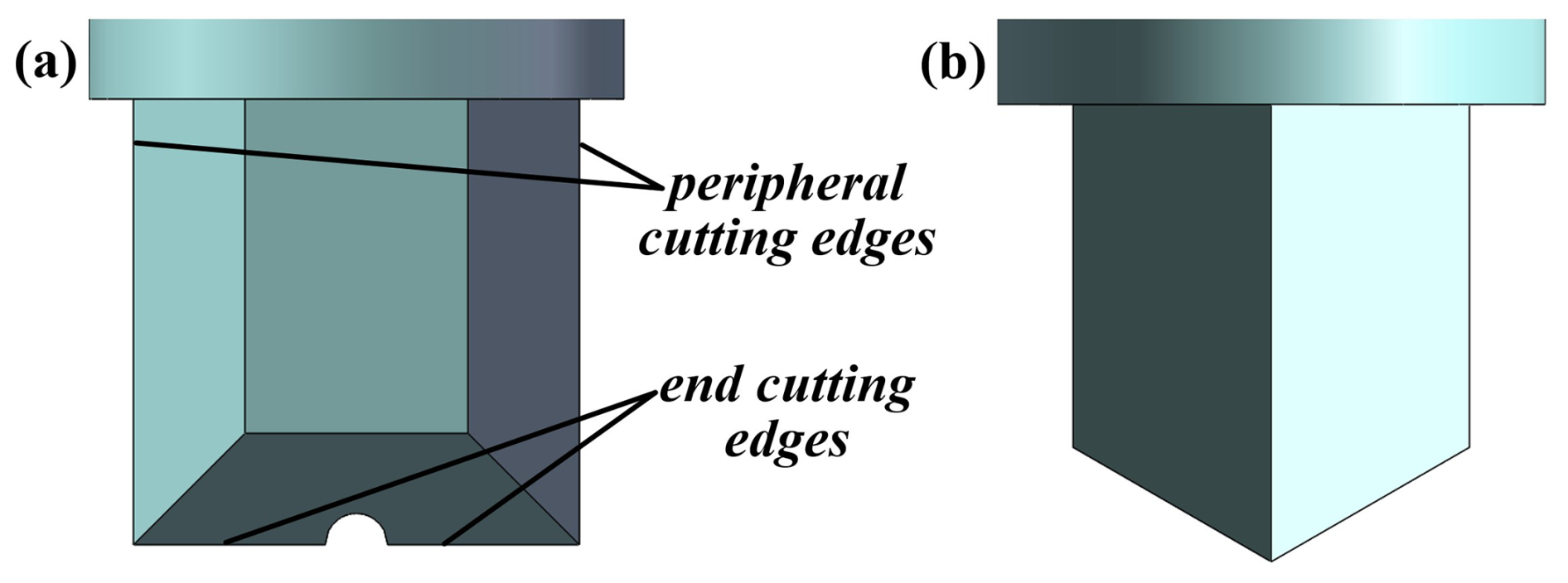
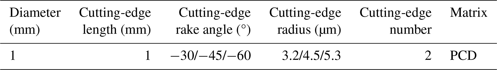
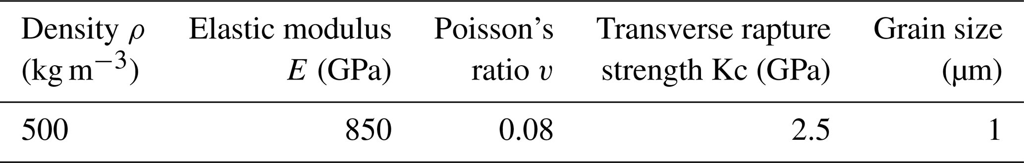
Based on previous studies on micromilling and micro PCD end mills, a micro-end mill is designed as shown in Fig. 1 (Cheng et al., 2018, 2008, 2011). For the PCD end mill with straight peripheral and end cutting edges, in order to analyze the influence of the geometries on the machining effects, three different rake angles are selected, which are −30, −45, and −60°, respectively. The main PCD cutter properties are shown in Table 1, and the material properties of the PCD material used in this study are shown in Table 2.
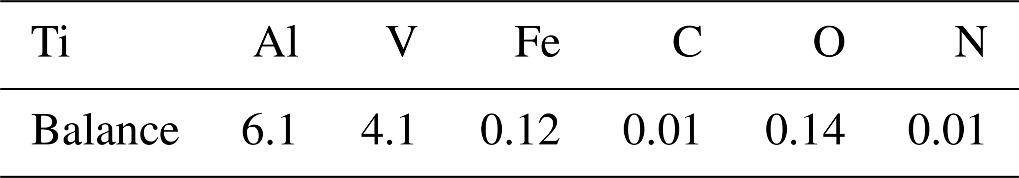
The workpiece used in the experiment is Ti-6Al-4V titanium alloy. The material properties and composition are shown in Tables 3 and 4, respectively.
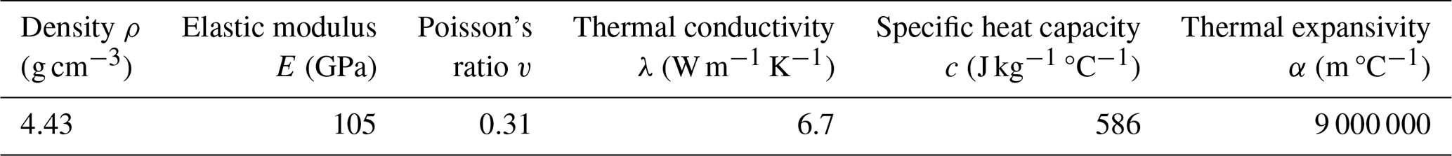
Table 4Material composition of Ti-6Al-4V titanium alloy (wt %).
2.2 Experimental setup
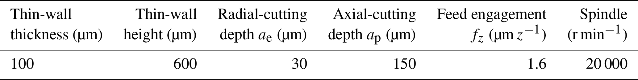
The CNC micromilling machine tool CarverPMS23_A8 is used to conduct the experiments, the programming resolution for each linear axis is 0.1 µm, and the maximum rotation speed of the spindle is 36 000 min−1. The cutting force is measured by Kistler 9257B dynamometer. Micromilling parameters of Ti-6Al-4V thin wall are selected and shown in Table 5. Based on the previous micromilling experiments for thin walls made of H59 Brass material, the layered cutting method is used in the experiments. Based on the literature (Li et al., 2021a, b) the down-milling process is selected in this study.
Table 5The cutting-parameter selection for Ti-6Al-4V thin wall.
2.3 Experimental processing method
The CNC milling machine cutter CarverPMS23_A8 is used to conduct the experiments, as shown in Fig. 2. The programming resolution for each linear axis is 0.1 µm. The maximum rotation speed of the spindle is 36 000 min−1. Dry cutting, jet cold air (temperature: −5 °C), and oil mist cutting fluid (flow rate: 0.25 L min−1) are applied to the micromilling process. The system schematic of jet cold air and oil mist lubrication is shown in Fig. 3.
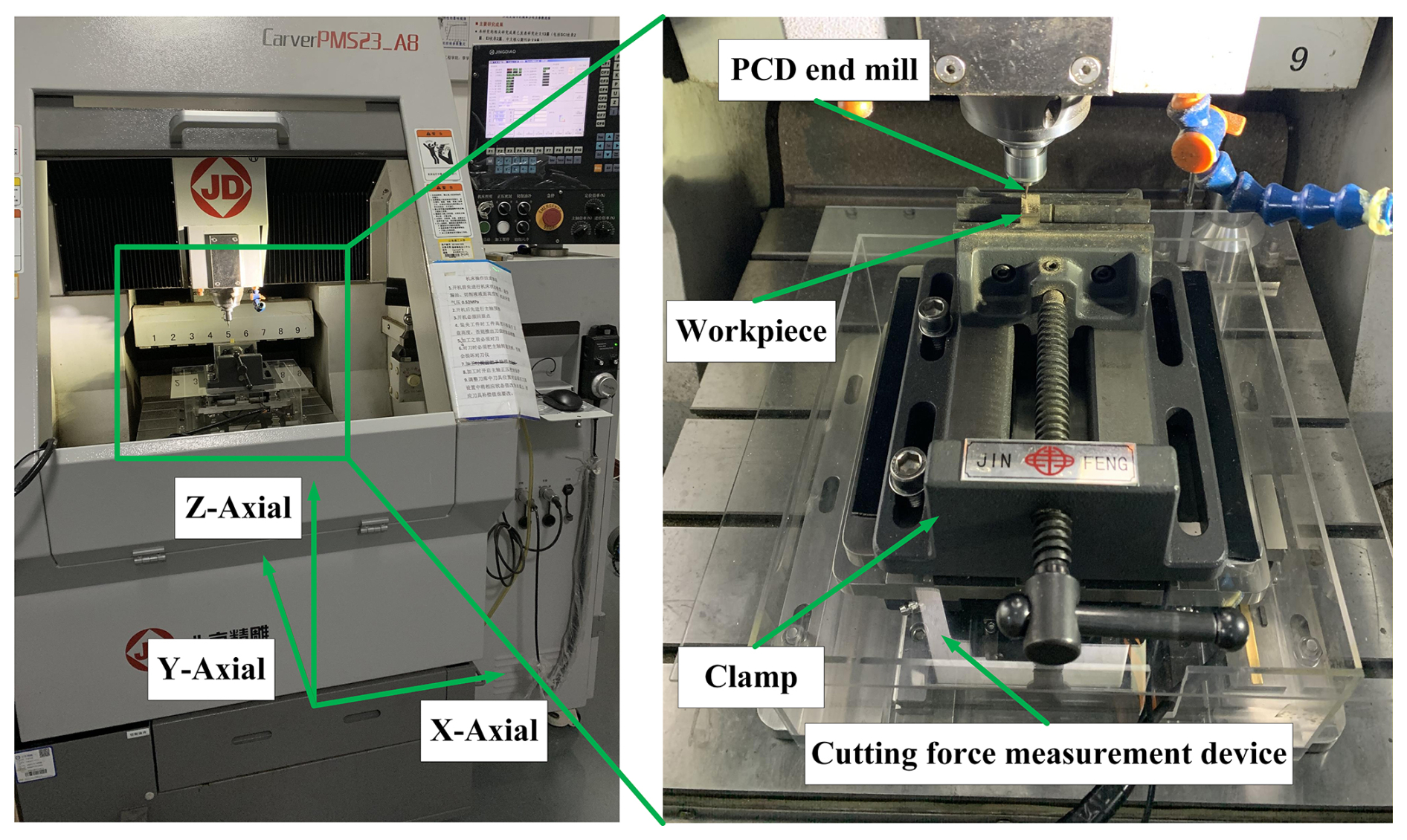
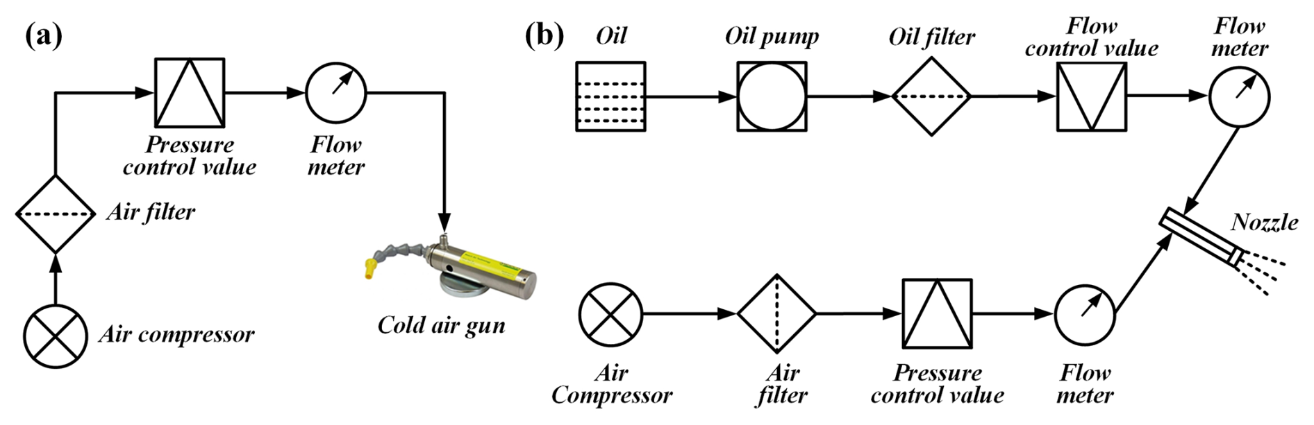
Figure 3Schematic view of jet cold air and oil mist applied: (a) components of the jet cold air system, (b) components of the oil mist lubrication system.
The micro-element method is used to model the milling force; that is, the tool is discretized into a finite number of axial disks along the axis of the tool. Figure 4 shows the schematic view of milling-force modeling of the tool by means of the micro-element method. The cutting situation of the straight-edge tool is different from that of the spiral one. It can be considered to be the case that the cutting state of the tool along the axial direction is consistent. As shown in Fig. 4, any position on the same cutting edge is simultaneously cut in from the cutting angle θst and cut out from the cutting angle θex.
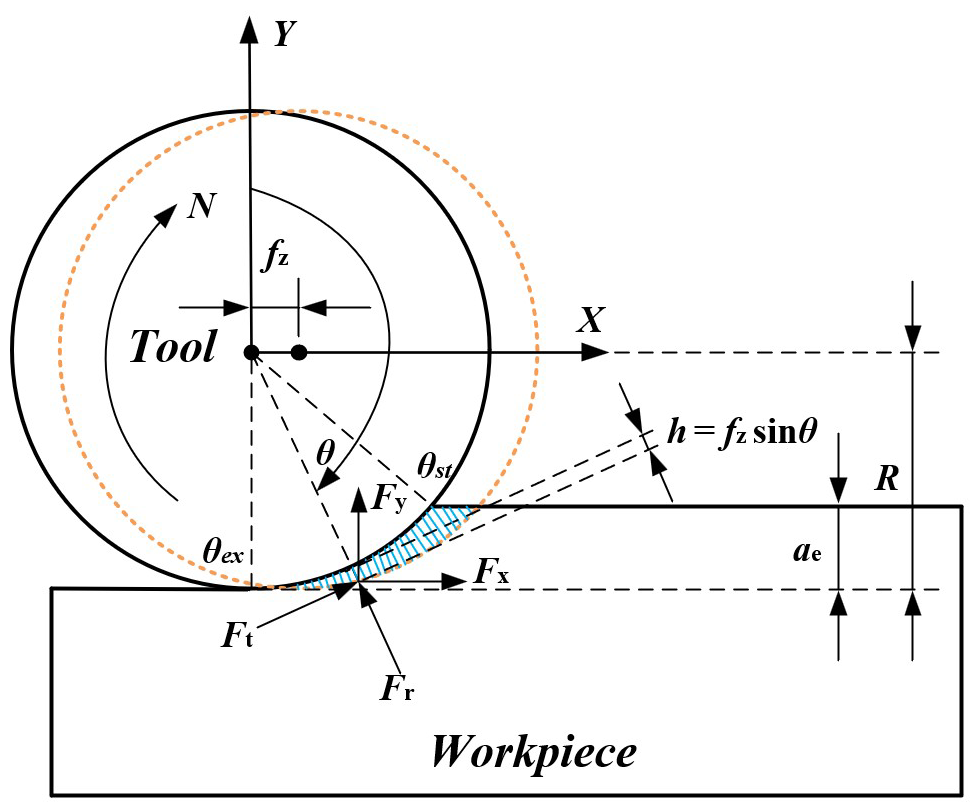
In micromilling, the cutting force generated by the tool in the cutting process mainly includes shear and plow cutting forces. It is assumed that the tangential force Ft and radial force Fr are proportional to the instantaneous cutting area, which can be expressed by Eq. (1).
In the above, dFt(θ) and dFr(θ) are tangential and radial components of milling forces, Kts and Krs are tangential and radial specific shear forces, and Ktp and Krp are tangential and radial specific plow cutting forces. θ is the position angle. h(θ) represents the instantaneous cutting thickness, which is represented by Eq. (2).
The radial cutting depth is less than the tool radius. Therefore, the cutting process is a single-edged intermittent cutting process. Namely, there is no simultaneous cutting engagement of two cutting edges. Therefore, only one cutting edge can be considered in the cutting-force modeling.
In order to solve the equation conveniently, the tangential force and radial force are converted into forces in each axis direction in the Cartesian coordinate system by Eq. (3).
Equation (3) is further simplified, as shown in Eq. (4).
As shown in Fig. 4, the position angle θ lies between the cut-in angle and the cut-out angle. The cut-in angle θst can be expressed by Eq. (5), and the cut-out angle θex is .
Therefore, at a given position angle θ, the sum of instantaneous cutting forces acting on the tool in all directions can be expressed by Eq. (6).
Equation (6) is expressed by Eq. (5) in matrix form:
where,
The value of K can be solved through Eq. (8); however, X is an irreversible matrix – it cannot be solved directly. Therefore, the new matrices F(A) and X(A) are formed by expanding the matrices F and X, as shown in Eqs. (9) and (10), respectively.
Equation (11) is a singular linear equation set of instantaneous cutting force and feed engagement. The tangential and radial specific shear forces Ktc and Krc and the tangential and radial specific plow cutting forces Ktp and Krp of the singular linear equation set can be solved by means of the linear regression method.
4.1 Specific cutting force
The specific cutting force can be obtained by substituting the measured cutting force during the experiment into Eq. (11). Figure 5 shows the change of specific cutting force with different cutting-edge rake angles. From Fig. 5a, with the decrease in cutting-edge rake angle, both tangential and radial specific shear cutting forces show an increasing trend. From Fig. 5b, with the decrease in cutting-edge rake angle, the tangential and radial specific plow cutting forces also show an increasing trend. With the decrease in cutting-edge rake angle, the cutting edge of the tool becomes dull after being sharp, which makes it difficult for the cutting edge to remove materials. Therefore, the specific shear and the specific plow cutting forces are constantly increasing. Therefore, choosing a tool with a larger rake angle is beneficial to reduce the cutting force generated in the cutting process, thus reducing the thin-wall deformation caused by the cutting forces.
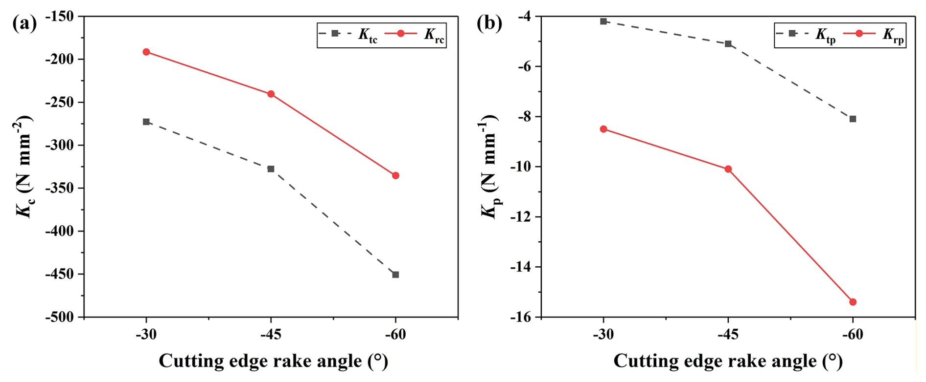
Figure 5The change in specific cutting forces with different cutting-edge rake angles: (a) specific shear force, (b) specific plow cutting force.
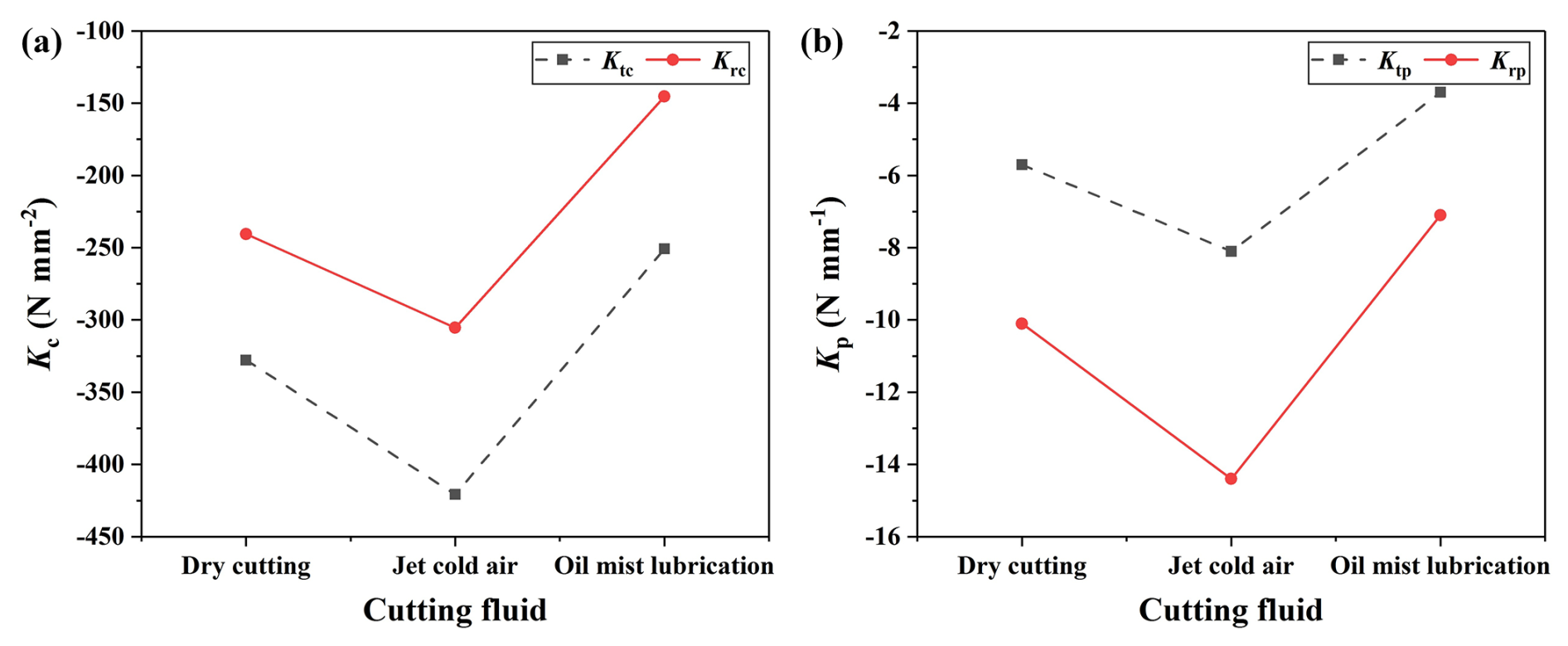
Figure 6The change in specific cutting force with different cutting fluids: (a) specific shear force, (b) specific plow cutting force.
Figure 6 shows the change in specific cutting force with different cutting fluids. From Fig. 6a, the specific shear force produced by the oil mist cutting fluid is the smallest, and that produced by the jet cold air is the largest. From Fig. 6b, the specific plow cutting force produced by the oil mist cutting fluid is the smallest, and that produced by the jet cold air is the largest. Oil plays a lubricating role in the machining process, which is beneficial in reducing the friction between the tool and the workpiece. Thus, the cutting forces are reduced. The jet cold air will make the workpiece in a low-temperature environment, which will lead to an increase in the hardness of the workpiece material, making cutting difficult and, thus, leading to the increase in cutting forces.
4.2 Surface roughness
The surface roughness is measured by an Olympus-DSX1000 ultra-depth microscope. Each feature is measured three times, denoted as Ra1, Ra2, and Ra3, and the average value of the three measurements is calculated to be the final measurement value.
Figure 7 shows the change of surface roughness with different cutting-edge rake angles. From Fig. 7, the surface roughness produced by the −45° tool rake angle is the smallest, and that produced by the −60° tool rake angle is the largest. Usually, the surface roughness is positively correlated with the cutting force; that is, the smaller the cutting force is, the smaller the surface roughness value will be. However, the experimental results shown here do not conform to this rule. The reason may be that titanium alloy is a kind of difficult-to-machine material, having low thermal conductivity and large elasticity, and the cutting heat generated in the cutting process can hardly be quickly conducted out of the cutting area, resulting in tool wear being accelerated, thus affecting the surface processing quality of the workpiece.
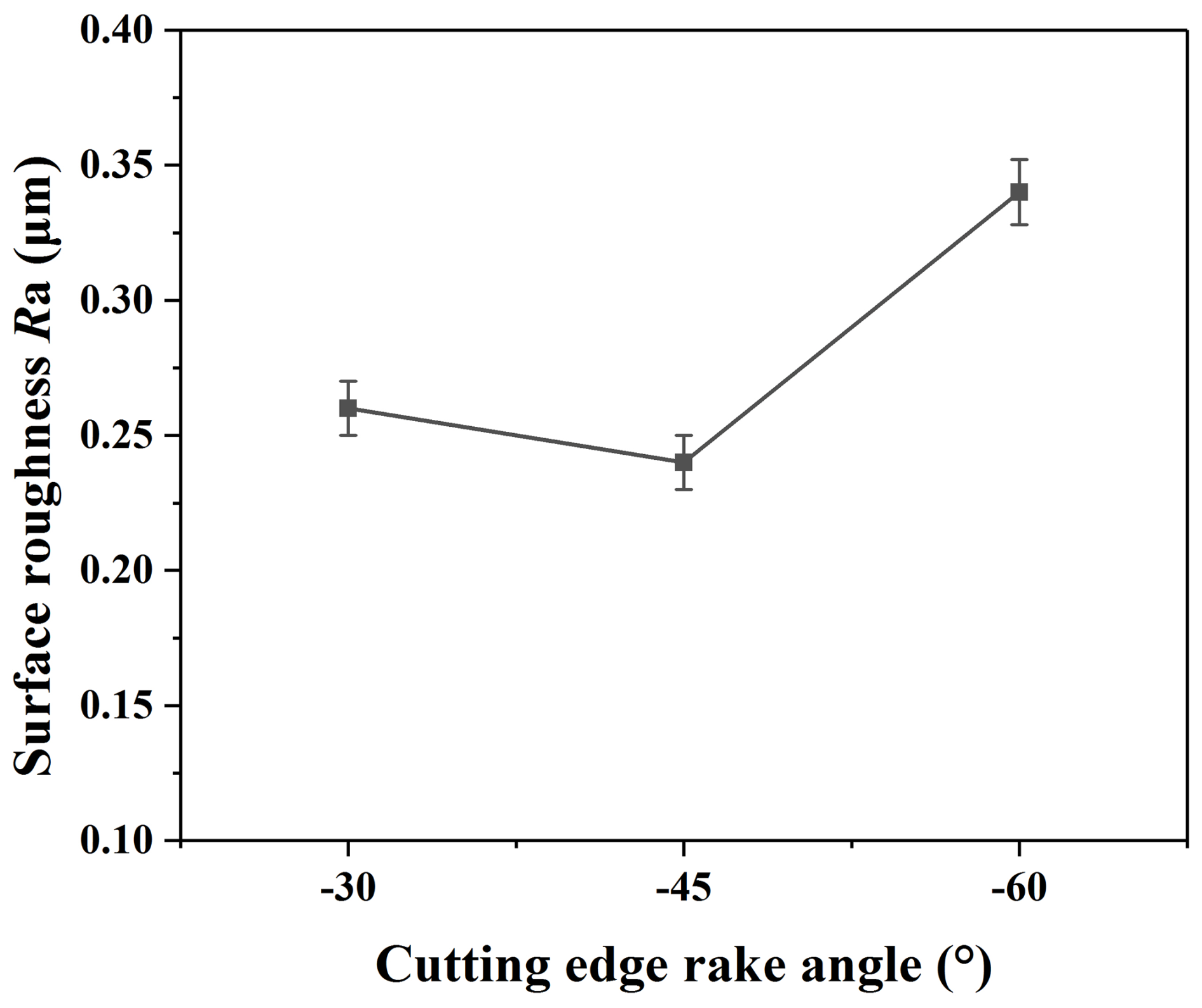
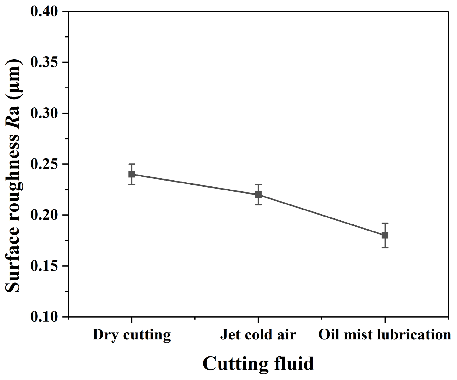
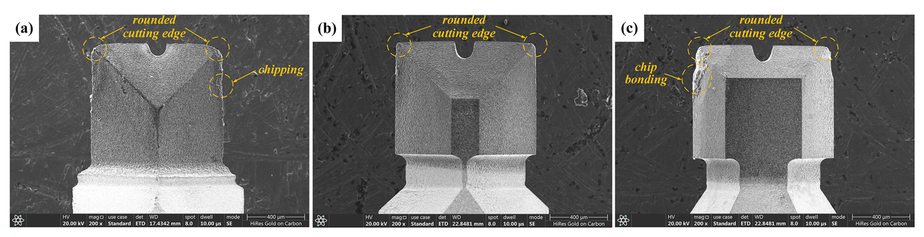
Figure 9The measurement results of tool wear with different cutting edge rake angles: (a) −30° cutting-edge rake angle, (b) −45° cutting-edge rake angle, (c) −60° cutting-edge rake angle.
Figure 8 shows the change in surface roughness with different cutting fluids. From Fig. 8, the surface roughness produced by oil mist is the smallest, and that produced by dry cutting is the largest. Oil mist produces the smallest cutting force, and so its surface roughness is the smallest. In the process of oil mist spraying, it can also take away part of the cutting heat generated in the cutting area, thus slowing down the tool wear and improving the surface processing quality of the workpiece. Although the cutting force produced by the jet cold air is the largest, the cold air will effectively reduce the temperature of the cutting area, thus slowing down the wear of the tool and reducing the surface roughness value.
4.3 Tool wear
The tool wear is measured by the Quanta-250 scanning electron microscope (SEM). Figure 9 shows the measurement result of tool wear by three kinds of PCD tools under dry cutting. Figure 9a shows the −30° cutting-edge rake angle tool wear measurement result, and it can be seen that the main wear forms are rounded cutting edges and chipping. Figure 9b shows the −45° cutting-edge rake angle tool wear measurement result, and it can be seen that the main wear form is a rounded cutting edge. Figure 9c shows the −60° cutting-edge rake angle tool wear measurement result; it can be seen that the main wear forms are rounded cutting edges and chip bonding. All of the above three tools show the same tool wear form of a rounded cutting edge. The main reason for this is that the tool tip is the main cutting part, and frequent participation in the cutting process leads to faster wear, which is a normal wear phenomenon. The degree of the rounded cutting edge of the three tools is inconsistent, indicating that the geometric angle of the tool has an important influence on tool wear. It was also found that the −45° cutting-edge rake angle tool wear is the smallest, and the −60° cutting-edge rake angle tool wear is the largest.
4.4 Dimensional error
The thickness of the thin wall is also measured by the Quanta-250 SEM. The thickness of the thin wall is measured by selecting six positions at equal distance along the height direction of the thin wall. Then the average value is calculated as the thickness of the thin wall.
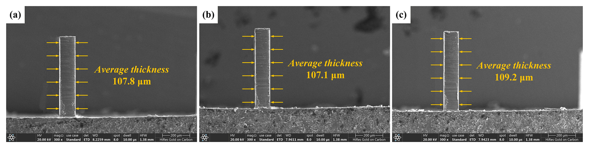
Figure 10The measurement results of the thin wall with different cutting-edge rake angles: (a) −30° cutting-edge rake angle, (b) −45° cutting-edge rake angle, (c) −60° cutting-edge rake angle.
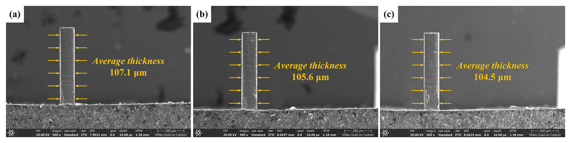
Figure 11The measurement results of the thin wall with different cutting fluids: (a) dry cutting, (b) jet cold air, (c) oil mist lubrication.
Figure 10 shows the measurement result of the thin wall processed by three kinds of PCD end mills under dry cutting. Figure 11 shows the measurement results of the thin wall processed by three kinds of cutting fluids with the −45° cutting-edge rake angle PCD end mill. The overall thickness of the thin wall is uniform, and there are no obvious bending deformations. However, there is a certain dimensional error between the actual measured thickness and its nominal thickness, which may be mainly caused by the elastic deformation of the workpiece and the tool. In comparison to the thin-wall thickness with a dimensional error of approximately 10 %, as reported in the reference (Jia et al., 2021), this study achieves a dimensional error as low as 4.5 % in terms of the thin-wall thickness, demonstrating a significant improvement in machining quality.
Figure 12 shows the change in the dimensional error of the thin wall with different cutting-edge rake angles, from which it can be seen that the dimensional error of the thin wall machined by the PCD end mill with a −45° cutting-edge rake angle is the smallest. However, the thin wall corresponding to the minimum cutting force is not the one with the smallest dimensional error, which is inconsistent with the previous research conclusion (Li et al., 2022). A possible reason for this difference is that PCD tools have different degrees of tool wear, which leads to the reduction in their effective cutting diameter, thus reducing the actual radial-cutting depth and increasing the residual amount of thin-wall thickness.
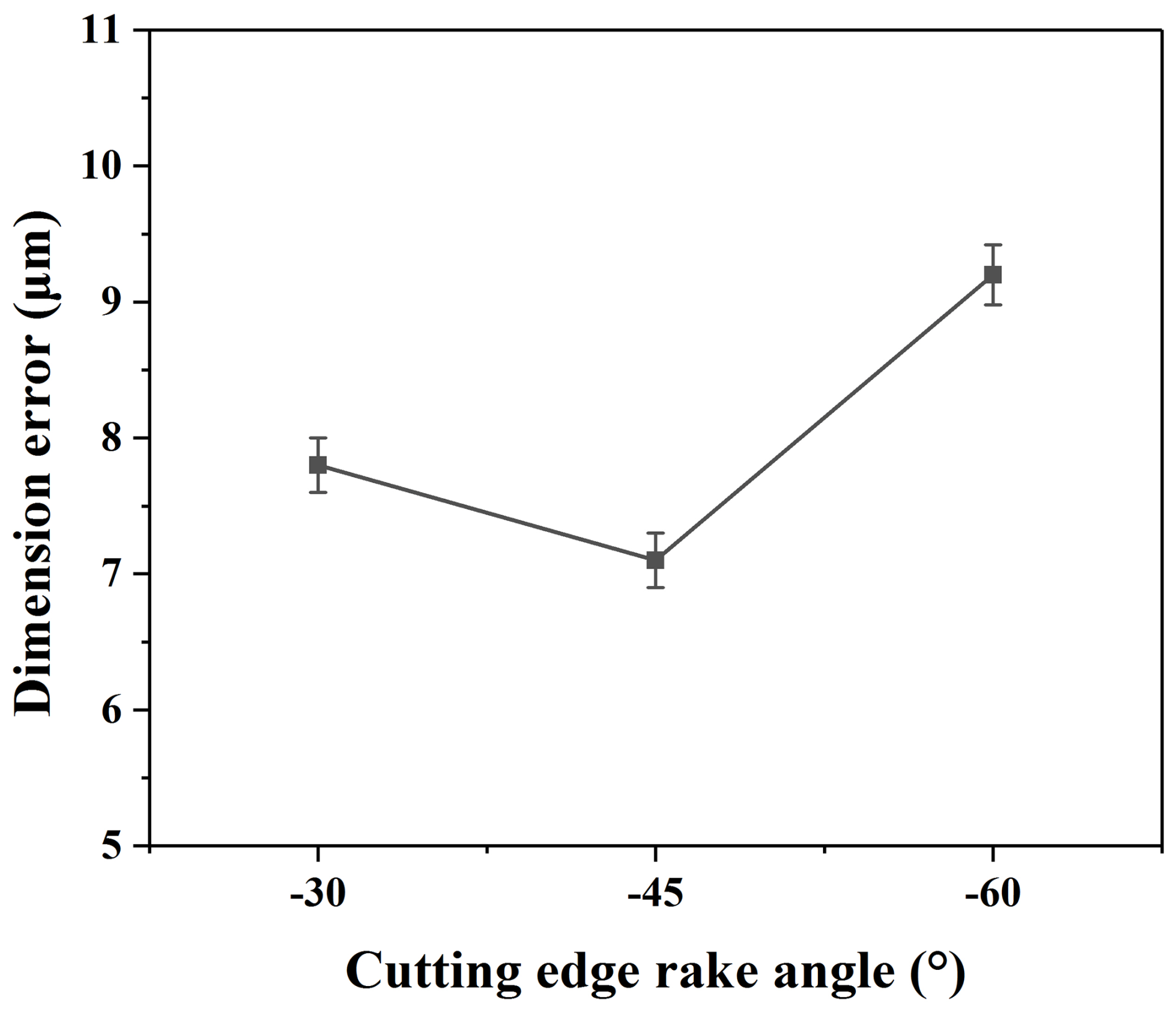
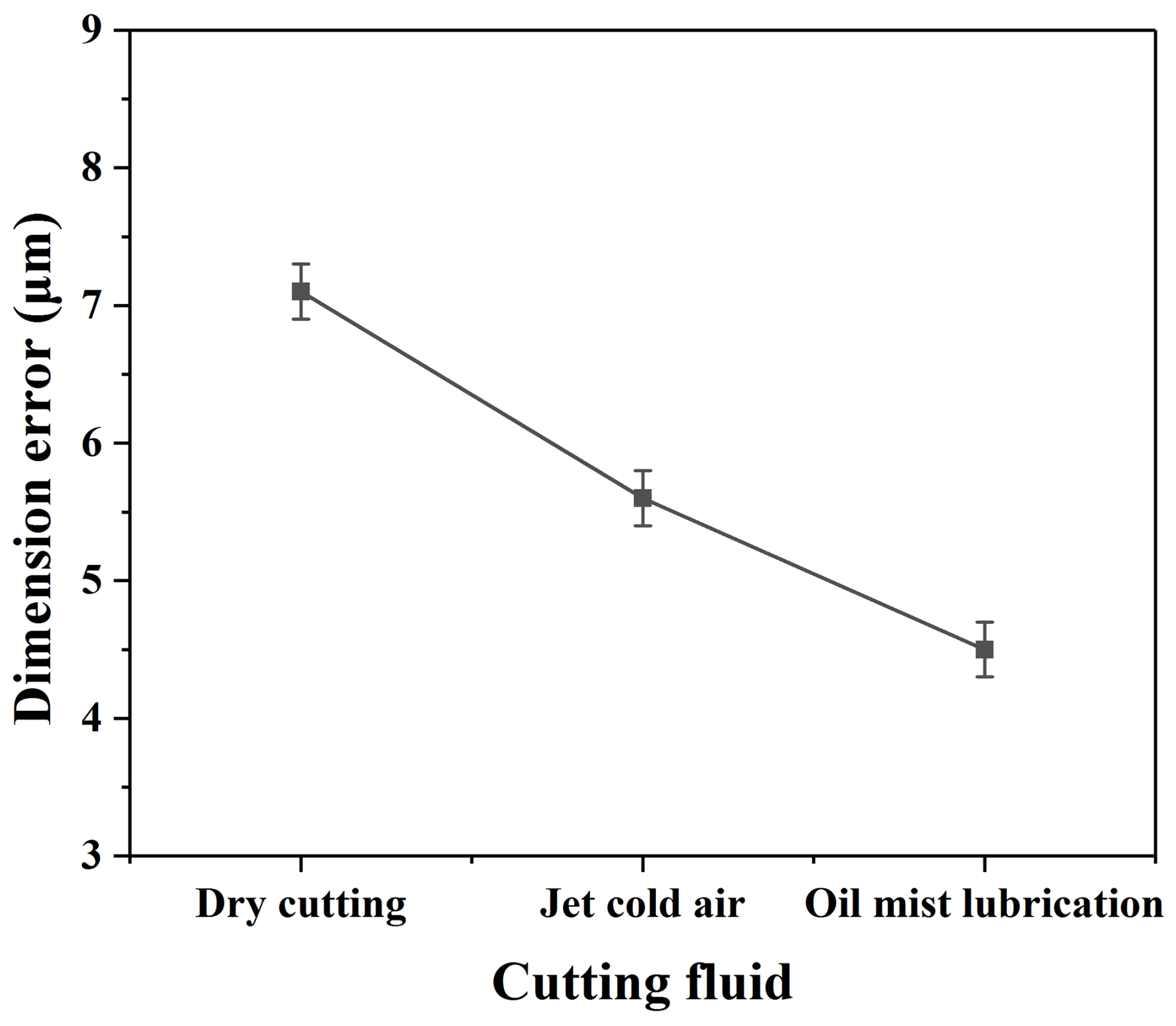
Figure 13 shows the change in the dimensional error of the thin wall with different cutting fluids. The dimensional error of the thin wall machined by oil mist cutting fluid is the smallest. Jet cold air is also an effective cutting fluid to improve the thin-wall dimensional accuracy compared with dry cutting.
4.5 Discussion
Based on the above experimental results and analysis, it can be seen that the specific cutting force produced by the −30° rake angle is the smallest, but the surface roughness, tool wear, and dimensional error produced by the −45° rake angle are the smallest. There is no obvious correlation between specific cutting force and surface roughness, tool wear, and dimensional error. Therefore, the PCD micro-end mill with a −45° rake angle is more suitable for cutting high-quality thin walls made of the Ti-6Al-4V titanium alloy.
Oil mist cutting fluid produces not only the smallest specific cutting force but also the smallest surface roughness value and dimensional error. Therefore, oil mist cutting fluid can be used for cutting high-quality thin walls made of the Ti-6Al-4V titanium alloy.
The results of this study indicate that, in addition to optimizing cutting parameters, improving the machining quality of titanium alloy components can also be achieved by modifying tool geometry, applying auxiliary machining processes, and integrating these strategies. This multifaceted approach demonstrates how machining quality can be enhanced through coordinated adjustments across several factors. Furthermore, this research provides theoretical and technical guidance for the high-quality machining of other difficult-to-machine materials in the aerospace industry.
In this study, the micromilling process for thin walls made of the Ti-6Al-4V titanium alloy is studied using the customized micro PCD end mills with straight cutting edges and different cutting fluids. The following conclusions are drawn:
-
The specific cutting force has a negative correlation with the cutting-edge rake angle. Both specific shear and plow cutting forces increase with the decrease in cutting-edge rake angle. This means that the larger the rake angle of the tool, the smaller the cutting force required to remove the unit volume of material. However, the surface roughness, tool wear, and dimensional error have no linear relation with the cutting-edge rake angle.
-
The oil mist is the better cutting fluid compared with dry cutting and jet cold air, producing not only the smallest specific cutting force but also the smallest surface roughness and dimensional error. Therefore, oil mist is beneficial to micromilling of thin walls made of the Ti-6Al-4V titanium alloy by PCD end mills.
-
In the actual aerospace industry, components often feature complex curved surfaces. The theories and techniques developed in this study for micromilling straight thin walls can be extended to guide the high-quality machining of such complex curved components in subsequent work. The findings of this study can directly guide the manufacturing of titanium alloy precision parts, including aerospace micro heat sinks, medical porous implants, and optical microcavities. At the same time, key indicators such as stability, efficiency, and cost-effectiveness, which require focused validation during the transition from laboratory processes to industrial application, have been identified.
-
Future research can expand the current research paradigm to other difficult-to-machine material systems and explore adaptive machining strategies to address the dynamic changes in thin-wall stiffness during processing. Simultaneously, efforts can focus on developing functionalized PCD tools (with micro-textures or coatings) and integrating online monitoring technologies to enable intelligent prediction and compensation of the machining process. Furthermore, moving beyond traditional oil mist, the performance of advanced media such as nanofluids and supercritical CO2 can be evaluated, accompanied by comprehensive sustainability assessments.
All data are given in the paper. No further data sets were used.
XC and YL proposed the research methods, and YL conducted the experiments and analyzed the experimental results. YL wrote the paper.
The contact author has declared that neither of the authors has any competing interests.
Publisher's note: Copernicus Publications remains neutral with regard to jurisdictional claims made in the text, published maps, institutional affiliations, or any other geographical representation in this paper. The authors bear the ultimate responsibility for providing appropriate place names. Views expressed in the text are those of the authors and do not necessarily reflect the views of the publisher.
This research has been supported by the Qilu Medical University Scientific Research Startup Foundation for High-Level Talents (grant no. X2024BSJJ011) and the Qilu Medical University University-Level Scientific Research Project (grant no. X24ZKMS08).
This paper was edited by Jia Ge and reviewed by Emre Arabaci and one anonymous referee.
Aydın, M. and Köklü, U.: Analysis of flat-end milling forces considering chip formation process in high-speed cutting of Ti6Al4V titanium alloy, Simul. Model. Pract. Th., 100, 102039, https://doi.org/10.1016/j.simpat.2019.102039, 2020.
Cheng, X., Nakamoto, K., and Sugai, M.: Development of ultra-precision machining system with unique wire EDM tool fabrication system for micro/nano-machining, CIRP. Ann-Manuf. Techn., 57, 415–420, 2008.
Cheng, X., Wang, Z. G., and Nakamoto, K.: A study on the micro tooling for micro/nano milling, Int. J. Adv. Manuf. Tech., 53, 523–533, 2011.
Cheng, X., Liu, J. C., and Zheng, G. M.: Study of microcutting fundamentals for peripheral and end cutting edges in micro-end-milling, J. Micromech. Microeng., 28, 015011, https://doi.org/10.1088/1361-6439/aa9a73, 2018.
Denkena, B., Vehmeyer, J., and Niederwestberg, D.: Identification of the specific cutting force for geometrically defined cutting edges and varying cutting conditions, Int. J. Mach. Tool. Manu., 82–83, 42–49, 2014.
Farhadmanesh, M. and Ahmadi, K.: Online identification of mechanistic milling force models, Mech. Syst. Signal. Pr., 149, 107318, https://doi.org/10.1016/j.ymssp.2020.107318, 2021.
Gang, L.: Study on deformation of titanium thin-walled part in milling process, J. Mater. Process. Tech., 209, 2788–2793, 2009.
Gonzalo, O., Beristain, J., and Jauregi, H.: A method for the identification of the specific force coefficients for mechanistic milling simulation, Int. J. Mach. Tool. Manu., 50, 765–774, 2010.
Gradisek, J., Kalveram, M., and Weinert, K.: Mechanistic identification of specific force coefficients for a general end mill, Int. J. Mach. Tool. Manu., 44, 401–414, 2004.
Grossi, N., Sallese, L., and Scippa, A.: Speed-varying cutting force coefficient identification in milling, Precis. Eng., 42, 321–334, 2015.
Han, J. J., Hao, X. Q., and Li, L.: Investigation on micro-milling of Ti-6Al-4V alloy by PCD slotting-tools, Int. J. Precis. Eng. Man., 21, 291–300, 2020.
Jia, Z. Y., Lu, X. H., and Gu, H.: Deflection prediction of micro-milling Inconel 718 thin-walled parts, J. Mater. Process. Tech., 291, 117003, https://doi.org/10.1016/j.jmatprotec.2020.117003, 2021.
Jin, Y., Wu, X., and Gao, F.: Investigation of Residual Stress in Ice-Covered Milling of Ti-6Al-4V Alloy Thin-Walled Parts with Experimental and Finite Element Simulations. J. Mater. Eng. Perform., https://doi.org/10.1007/s11665-025-11621-8, 2025.
Li, Y., Cheng, X., and Ling, S. Y.: Study on deformation and compensation for micromilled thin walls with high aspect ratios, Int. J. Adv. Manuf. Tech., 117, 1797–1806, 2021a.
Li, Y., Cheng, X., and Ling, S. Y.: On-line compensation for micromilling of high-aspect-ratio straight thin walls, Micromachines, 12, 603, https://doi.org/10.3390/mi12060603, 2021b.
Li, Y., Cheng, X., and Zheng, G. M.: Dynamic modeling and in-process parametric compensation for fabricating micro straight thin walls by micromilling, J. Mater. Res. Technol., 18, 2480–2493, 2022.
Machai, C., Iqbal, A., and Biermann, D.: On the effects of cutting speed and cooling methodologies in grooving operation of various tempers of β-titanium alloy, J. Mater. Process. Tech., 213, 1027–1037, 2013.
Rauf, A., Khan, M. A., and Jaffery, S. H. I.: Effects of machining parameters, ultrasonic vibrations and cooling conditions on cutting forces and tool wear in meso scale ultrasonic vibrations assisted end-milling (UVAEM) of Ti-6Al-4V under dry, flooded, MQL and cryogenic environments-A statistical analysis, J. Mater. Res. Technol., 30, 8287–8303, 2024.
Rubeo, M. A. and Schmitz, T. L.: Mechanistic force model coefficients: A comparison of linear regression and nonlinear optimization, Precis. Eng., 45, 311–321, 2016.
Sabkhi, N., Moufki, A., and Nouari, M.: Prediction of the hobbing cutting forces from a thermomechanical modeling of orthogonal cutting operation, J. Manuf. Process., 23, 1–12, 2016.
Shanmugam, R., Baloor, S. S., and Koklu, U.: Machining Temperature, Surface Integrity and Burr Size Investigation during Coolant-Free Hole Milling in Ti6Al4V Titanium Alloy, Lubricants., 11, 349, https://doi.org/10.3390/lubricants11080349, 2023.
Venkata, S. K. N., Suvin, P. S., and Vipindas, K.: Evaluation of machining performance of indigenously developed Coconut Oil based green cutting fluid under Minimum Quantity Lubrication condition, J. TRIBOL-T. ASME, https://doi.org/10.1115/1.4069518, 2025.
Wang, Z., Chen, G., and Wang, J.: Variable direction shear deformation induced strengthening mechanism of Ti-6Al-4V alloy treated by a novel ultrasonic milling-burnishing process, J. Manuf. Process., 144, 294–310, 2025.
Wu, G., Li, G. X., and Pan, W. C.: Experimental investigation of eco-friendly cryogenic minimum quantity lubrication (CMQL) strategy in machining of Ti-6Al-4V thin-wall part, J. Clean. Prod., 357, 131993, https://doi.org/10.1016/j.jclepro.2022.131993, 2022.
Yi, J., Wang, X. B., and Jiao, L.: Research on deformation law and mechanism for milling micro thin wall with mixed boundaries of titanium alloy in mesoscale, Thin. Wall. Struct., 144, 106329, https://doi.org/10.1016/j.tws.2019.106329, 2019.
Zhang, T., Liu, Z. Q., and Sun, X. D.: Investigation on specific milling energy and energy efficiency in high-speed milling based on energy flow theory, Energy., 192, 116596, https://doi.org/10.1016/j.energy.2019.116596, 2020.