the Creative Commons Attribution 4.0 License.
the Creative Commons Attribution 4.0 License.
 | 05 Dec 2025
Research on the design and characteristics of a new type of magnetic levitation spring
Manman Xu
Jiajun Wang
Zhitao Zhang
Yonghong Wu
Xiangdong Wang
A design method for a vehicle vibration reduction system based on permanent magnetic springs was developed in response to the issue of electric vehicle transmission dampers failing to effectively absorb energy, resulting in inadequate damping and reduced comfort. This method employs repulsive forces between aligned permanent magnets to replace the traditional spring support of the vehicle, generating a damping force through the axial movement of the magnets and the tube. A numerical model describing the repulsive force of the magnetic suspension spring was established, elucidating the impact of the gap between magnets on the repulsive force. The reliability of the mathematical model was verified through repulsion force experiments, and potential sources of error were analyzed. A 6-degrees-of-freedom test rig was constructed, and results indicate that compared with the non-conductor shell, the damping ratio of the magnetic levitation spring increased by about 103.69 % when a conductor shell was added, effectively dissipating oscillation energy. Finally, comprehensive vehicle experiments were conducted using an electric vehicle model. Vibration tests under various road conditions, based on human comfort evaluation standards, showed that the magnetic suspension spring significantly reduces vibrations, leading to a notable enhancement of human comfort. These results validate the proposed method and provide a theoretical basis for the design of permanent magnetic spring vibration reduction systems.
- Article
(1833 KB) - Full-text XML
- BibTeX
- EndNote


With the rapid advancement of new energy electric vehicles and the enhancement of living standards, there is an increasing demand for the safety and comfort of electric vehicle products (Wang, 2024). Conventional damping shock absorbers exhibit limited anti-roll capabilities, lack energy absorption efficiency, and are susceptible to resonance with the vehicle, thereby compromising ride comfort. Notably, these shock absorbers suffer from a short service life, are prone to fatigue failure, and entail high maintenance costs due to their intricate design (Zhen, 2024). However, traditional dry friction damping suffers from more significant limitations. Based on dissipative theory, Liao et al. (2024) modeled the stages of dry friction wear using the entropy production rate, demonstrating that during the severe wear phase, the friction coefficient exhibits oscillatory behavior accompanied by a sharp increase in temperature at the friction interface. Furthermore, Ahmat et al.'s (2024) analysis demonstrates that dry friction induces significant tribological damage on the seal ring end face. The substantial frictional heat generated from this damage causes thermal deformation, degrading surface flatness and triggering self-excited vibrations. Therefore, permanent magnetic spring dampers offer significant advantages, including frictionless and lossless operation due to non-contact forces, coupled with superior damping capacity. Consequently, permanent magnetic springs, developed using permanent magnet materials, offer advantages such as an ultra-high magnetic energy product, intrinsic coercivity, and superior mechanical properties, garnering significant research attention in recent years (Shen et al., 2023).
Sacco and Moon (2022) have significantly improved the spring rate by employing additive manufacturing techniques, offering innovative approaches for the development of novel spring architectures. Sun et al. (2023) introduced a permanent magnet–spring–pendulum linkage variable stiffness mechanism for joint actuators, demonstrating that the integration of permanent magnetic springs can substantially enhance the mechanism's maximum pulling force. Robertson et al. (2012) investigated a non-contact permanent magnetic spring isolator featuring symmetrically arranged inclined rectangular permanent magnets and analyzed the influence of tilt angle and air gap size on the spring's stiffness and natural frequency. Gori et al. (2023) developed an electromagnetic damper that leverages the interaction between a moving magnet and a conductive cylinder, revealing that increased cylinder thickness enhances damping performance, whereas reduced gaps between the cylinder and magnet diminish it. Kim et al. (2023) proposed an innovative elastic friction damper utilizing advanced materials, which incorporates pre-compressed polyurethane springs and permanent magnet cubes to minimize residual strain and achieve superior energy dissipation. Liu et al. (2020) designed a suspension system with dual magnetorheological dampers positioned oppositely within an electric vehicle's rim, demonstrating rapid response times and continuously adjustable damping forces that meet the vibration-damping requirements for electric vehicles. Bei and Huang (2020) developed a comprehensive full-vehicle model based on multibody dynamics (MBD), significantly improving ride comfort, handling stability, and driving safety. Zhao et al. (2018) utilized the explicit dynamic finite element method to analyze the transient dynamics of non-pneumatic wheels traversing grooves, creating a non-pneumatic wheel (NPW) three-dimensional finite element model that confirmed the superior stability of non-pneumatic wheels. Despite these advancements, the application of permanent magnetic springs as automotive dampers to enhance comfort remains unexplored.
To address the aforementioned issues, this paper proposes a novel magnetic spring design method for vibration reduction based on the repulsive force of permanent magnets. The system primarily relies on the strong repulsive force of permanent magnets to provide support and absorb vibrations. Additionally, copper rings are incorporated within the spring, generating eddy currents under the influence of the magnetic field and electric current, thereby forming damping. The damping can be automatically adjusted based on the magnitude of the eddy currents. The interaction between the repulsive force and damping results in a stable magnetic spring system. A systematic analysis of the repulsive and damping forces is conducted using numerical- and simulation-based methods, followed by comprehensive bench tests and full-vehicle experiments to validate the effectiveness of the proposed approach.
The structure of the designed magnetic levitation spring is illustrated in Fig. 1. The upper and lower plates are constructed from NdFe(52) permanent magnets (Li, 2023). Magnetic yokes are positioned on both sides of the upper and lower permanent magnets. The outer conductor shell is fabricated from Q235 steel, with copper rings embedded within it using a thermal expansion processing technique (Novak et al., 2012). The magnetic levitation spring is designed to achieve a load-bearing capacity of 750 N.
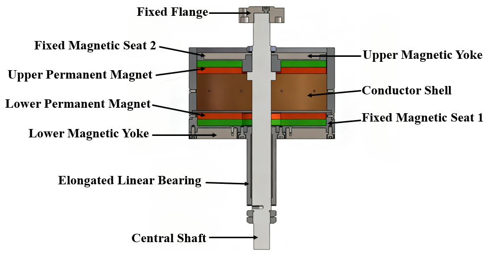
The working principle of the magnetic levitation spring is as follows: when the spring is at rest, the repulsive force between the upper and lower permanent magnets balances the external pressure. During the relative motion of the permanent magnets, the magnetic field lines penetrate the copper ring, altering the magnetic flux within the ring. This change induces an eddy current in the conductor cylinder. The eddy current generates a secondary magnetic field due to the magnetic effect of the current, which interacts with the original magnetic field, thereby opposing the initial motion. This interaction provides damping for the magnetic levitation spring, effectively attenuating external vibrations (Yang, 2017).
3.1 Numerical analysis of the repulsive force
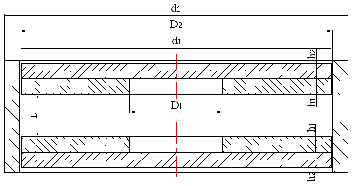
The schematic diagram of the permanent magnet and magnetic yoke is shown in Fig. 2, where D1 represents the diameter of the inner hole of the permanent magnet, d2 represents the outer diameter of the permanent magnet and magnetic yoke, h1 is the thickness of the permanent magnet, and h2 is the thickness of the magnetic yoke. The spatial magnetic flux density Bg at magnetic pole distance L can be determined using the following formula (Liu, 2019):
In theory, the attraction and repulsion forces between permanent magnets are equal. However, due to the inclination of the magnetization direction under repulsive conditions, the actual repulsive force is typically less than the attractive force. For calculation purposes, the attractive force between two magnets is approximated as twice the attraction between a magnet and an iron block. Based on the energy formula, the relationship can be expressed as
where E represents the coupling energy between the permanent magnet (PM) and ferromagnetic armature, Lg specifies the distance between the PM pole face and armature surface, Sg represents the magnetized area of the PM working surface, Bg represents the magnetic flux density in the air gap, Hg represents the magnetic field strength in the air gap, and μ0 represents the permeability of the vacuum ( H m−1).
Therefore, the formula for the magnetic attraction force in the vertical direction (in SI units) is
If CGS units are used, then Eq. (3) becomes
In Eq. (3), the unit of force Fattraction is dyne (dyn), the unit of Bg is gauss (G), and the unit of Sg is square centimeters (cm2).
When the gap between the magnets is zero, if the unit of force is converted to kilogram-force (kgf), then Eq. (4) is converted to Eq. (5) (1 kg = 9.8 N, 1 N = 0.12 kg; Zhao and Wang, 1991):
When the magnets are in a non-zero air gap state, considering the influence of magnetic reluctance within the permanent magnets and the external magnetic leakage factors, a correction coefficient is introduced. The formula for calculating the repulsive force between the two permanent magnets is given by Eq. (6):
Considering that magnetic leakage varies with the relative positions of the permanent magnets, a correction factor ∂ ranging from 3 to 15 is introduced. A larger value ∂ is applied for greater distances, while a smaller value is used for shorter distances. By substituting the parameters of the N52-grade neodymium–iron–boron permanent magnets into the formula, the relationship between the repulsive force of the magnetic spring and the distance is derived. The results indicate that the repulsive force of the magnetic levitation spring decreases exponentially with increasing distance. At the minimum distance of 5 mm, the maximum repulsive force is 885.3 N, while at the maximum distance of 60 mm, the repulsive force reduces to approximately 12 N.
3.2 Numerical analysis of the damping force
In the permanent magnetic spring investigated in this study, the permanent magnet is enclosed within a conductor shell. When the air gap between the permanent magnet and the conductor shell is minimal, magnetic leakage is negligible. When a relative motion with velocity v occurs between the permanent magnet and the conductor, the current density J induced by eddy currents in the conductor can be expressed as (Ye et al., 2018)
In the model of the permanent magnetic spring, the magnetization direction of the permanent magnet is parallel to the direction of motion. According to the definition of Lorentz force, the damping force Fc in the z direction can be obtained as
where rbig, rsmall, and σ are the outer diameter, inner diameter, and conductivity of the conductor shell, respectively; H is the distance between like poles of the permanent magnet; and h represents the height of the entire permanent magnetic spring.
Table 1Geometric parameters of magnetic levitation springs (mm).
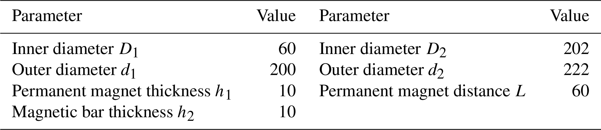
Based on the design objectives and the theoretical analysis above, the geometric structure parameters of the magnetic levitation spring are selected, as shown in Table 1.
Bench experiments are conducted to further analyze the repulsive and damping characteristics of the magnetic levitation spring, providing an assessment of the design's rationality.
4.1 Model simulation analysis
Maxwell software was employed for electromagnetic analysis, with a focus on examining the magnetic field distribution of the magnetic levitation spring and investigating the variation of magnetic force with distance. The size parameters are shown in Table 1, assuming that the lower permanent magnet in the model is fixed, while the upper permanent magnet moves downward at a speed of 2 mm s−1, with an initial displacement of 55 mm.
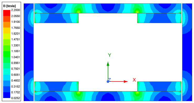
As shown in Fig. 3, the contour map of magnetic flux density indicates that the magnetic field of the regular geometric model presents a symmetrical spatial distribution. In addition, the figure highlights the effectiveness of the magnetic yoke in constraining the magnetic field, preventing the magnetic field from penetrating the magnetic yoke and leaking into the external environment.
4.2 Repulsive force test
The magnetic levitation spring is designed to support the gross vehicle weight and must exhibit exceptional load-bearing capacity. Initially, the upper section of the magnetic levitation spring is detached, and its self-weight is measured using a force gauge. The equilibrium position under its weight is designated as the starting point. Subsequently, weights are sequentially added to the load-bearing platform, with each weight measured, until the distance between the two magnets reaches 5 mm.
Under the condition of the same material parameters of the magnet, the results of the numerical analysis, finite element analysis, and experimental test are compared and analyzed. As shown in Fig. 4, the findings demonstrate that the repulsive force decays exponentially as the distance increases. The trends of the curves for the calculated results, experimental data, and simulations are highly consistent. The theoretical maximum value is 885.3 N, the simulated maximum value is 884.5 N, and the experimental maximum value is 882.8 N. The maximum deviation between the experimental and simulated values is 41.3 N, with an error of less than 4.7 %. The maximum deviation between the experimental and calculated values is 66.3 N, with the error controlled within 7.5 %. Most errors occur at points where the distance between the magnets is greater. The potential reasons for the discrepancies are as follows:
-
Magnetic field leakage when the distance between the two magnets in the magnetic levitation spring is relatively large;
-
The derived formula for the repulsive force cannot fully capture the actual working conditions, leading to deviations between the calculated results and the actual values;
-
Simplifications of the overall model and mesh size during the simulation process cause the simulation results to deviate from the experimental values.
-
Interference from other metallic components in the experimental environment affects the magnetic field.
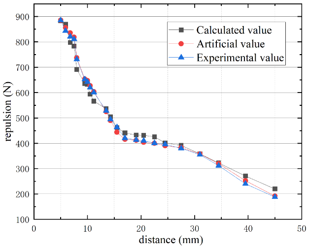
Figure 4Comparison of the repulsive force versus distance obtained from theoretical, simulation, and experimental methods.
4.3 Damping ratio test
To assess the vibration-damping performance of the magnetic levitation spring for small vehicles under real-world road conditions, an experiment was conducted using a cylinder-type damper test bench. The damping effect was evaluated by measuring the acceleration transmissibility of the magnetic levitation spring at various positions during the vibration process.
Experimental method and procedure
Start with a frequency lower than 1 Hz, and perform sinusoidal excitation on the magnetic levitation spring assembly while measuring the vibration acceleration at both the upper and lower ends.
Calculate the acceleration transmission ratio at different frequencies using Eq. (9):
At frequency f, the terms in the equation are defined as follows:
-
Ta(f) is the acceleration transfer ratio.
-
an(f) is the vibration acceleration at the upper end of the magnetic levitation spring (m s−2).
-
aA(f) is the vibration acceleration at the lower end of the magnetic levitation spring (m s−2).
Plot the acceleration transmission ratio curve. When plotting curve a, measurements should be taken under large excitation amplitude conditions, and the highest test frequency should be at least four times the resonance peak value.
When using single-frequency sinusoidal excitation, the excitation frequency can refer to the following values (Hz): 0.5, 0.6, 0.8, 1.0, 1.3, 1.6, 2.0, 2.5, 3.2, 4.0, 5.0, 6.3, 8.0, 10; additional measurement points should be added near the highest point a on the curve.
The resonance peak Tamax corresponds to the acceleration transmission ratio value at the highest point a on the curve shown in Fig. 5.
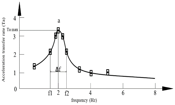
Calculate the damping ratio of the magnetic levitation spring using the following Eq. (10):
Remove the conductor shell from the magnetic levitation spring as a control experiment and repeat the above steps.
As shown in Fig. 6, the experimental apparatus was installed on the moving platform of a 6-degrees-of-freedom vibration table. The sensors transmitted 485 signals to the computer. Each frequency excitation was maintained for 30 s, during which the z-axis acceleration values from sensors K01 and K02 were recorded. The experiment was repeated multiple times, and the average values were calculated.
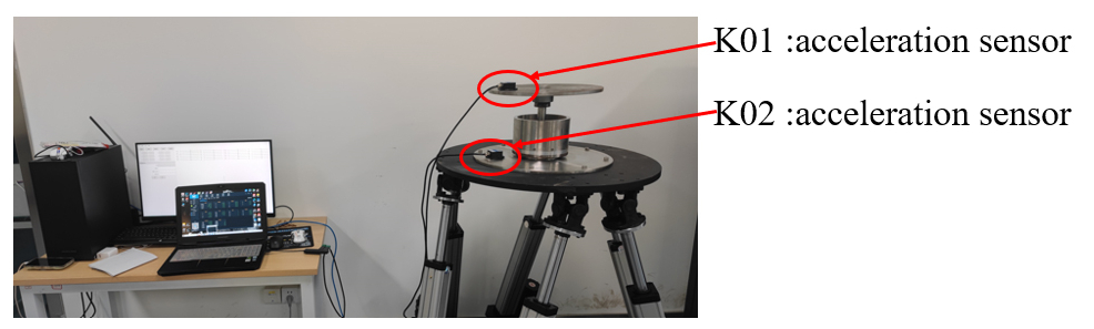
Figure 6 shows that nine-axis acceleration sensors K01 and K02 are mounted on the upper surface of the magnetic levitation spring and the moving platform of the 6-degrees-of-freedom vibration table, respectively.
Figure 7 illustrates the impact of the presence or absence of the conductor cylinder on the acceleration transmission rate. The results demonstrate that the conductor cylinder significantly influences the acceleration transmission rate of the magnetic levitation spring, particularly in the resonance peak region, where the effect is more pronounced. Additionally, at other frequencies, the acceleration transmission rate with the conductor cylinder is 1 %–5 % lower compared to the case without the conductor cylinder. Based on Eq. (10), the damping ratios of the magnetic levitation spring with and without the conductor shell are 1.8454 and 0.9060, respectively. The damping ratio with the conductor cylinder installed is significantly better than without it. Compared to traditional damping shock absorbers, the magnetic levitation spring shock absorber exhibits superior performance in vibration reduction and anti-roll capability.
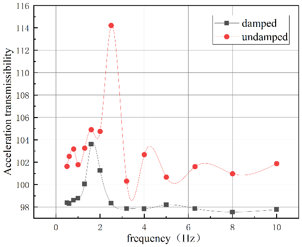
As shown in Fig. 7, the experimental results indicate that compared with the non-conductor shell, the damping ratio of the magnetic levitation spring increased by about 103.69 % when a conductor shell was added. The conductor shell significantly impedes the acceleration transmissibility, thereby serving as an effective mechanism for oscillation resistance and energy conversion.
5.1 Human comfort judgment
The vibration-damping effect of the magnetic levitation spring is evaluated based on human comfort (Wang et al., 2023). Comfort is assessed by considering the smoothness of the vehicle and the human response to vibration smoothness. There are two main evaluation indicators: weighted root mean square (RMS) acceleration aW and total weighted vibration level LaW. The vibration model is shown in Fig. 8.
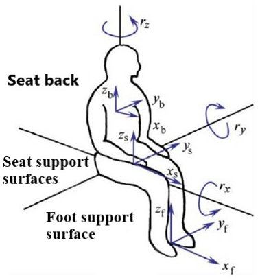
Figure 8 illustrates three primary locations where vibrations are transmitted to the human body in a seated position: the seat support surface (featuring linear vibrations in three directions and angular vibrations in three directions), the seat backrest (linear vibrations in three directions), and the foot support surface (angular vibrations in three directions), along with their corresponding triaxial vibrations. The human body demonstrates varying sensitivity to accelerations transmitted from different regions of the seat. The frequency weighting functions and axis weighting factors for these distinct seat positions are detailed in Table 2.
Table 2Frequency weighting functions w and axis weighting coefficient k for different seat positions.
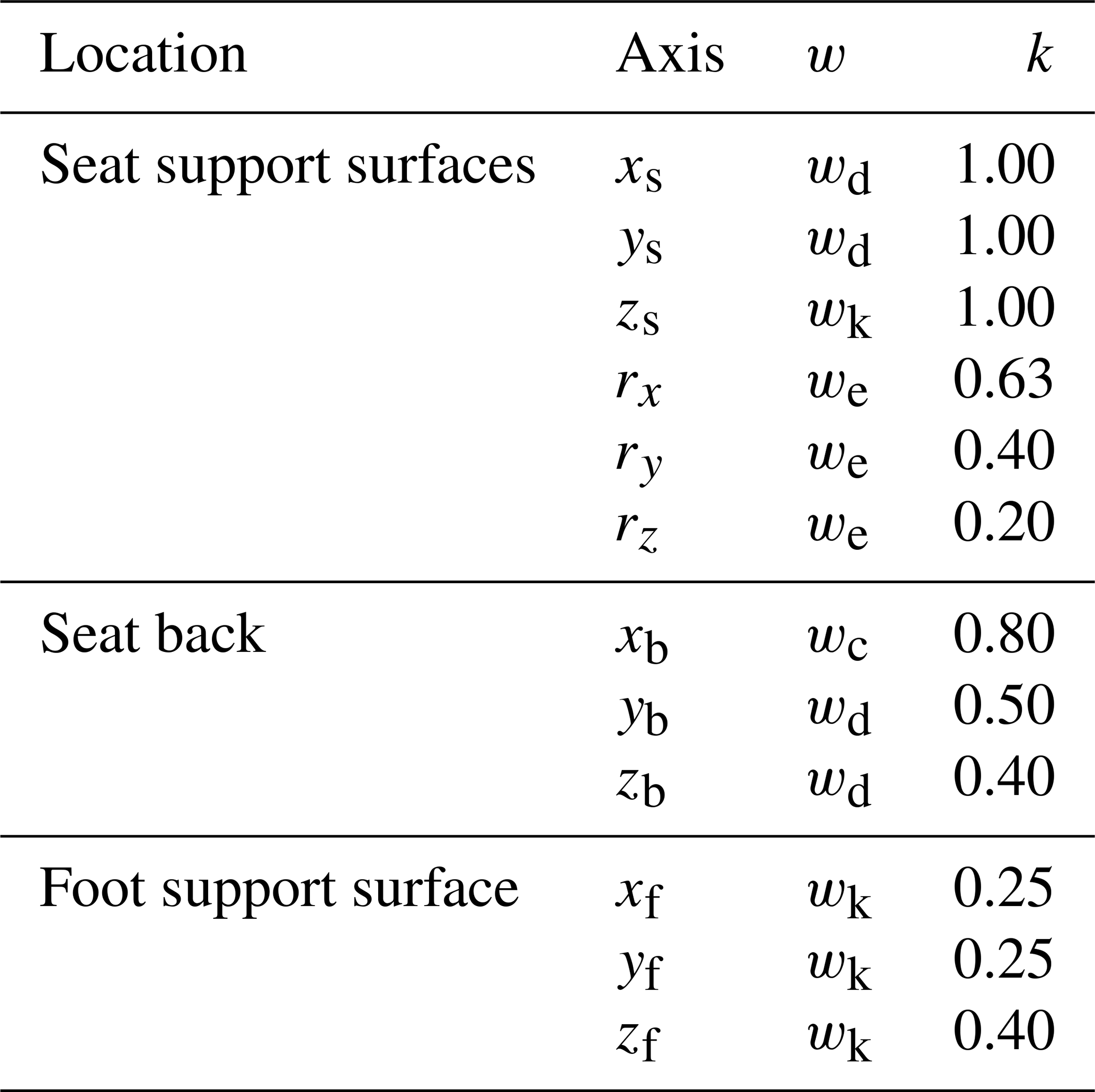
It can be observed that the human body is most sensitive to vibrations at the seat support surface. The expression for the frequency weighting function can be referenced from Eqs. (11) to (14):
Additionally, when evaluating the impact of vibration on health, the Chinese national standard specifies several considerations.
Only the axial vibrations along xs, ys, and zs are considered, and for the two horizontal axes xs and ys, the axis weighting coefficient is set to k = 1.4.
When evaluating the ride comfort of vehicles, the axial vibrations along xs, ys, and zs are considered.
The horizontal axes xb and yb of the backrest can be replaced by the horizontal axes xs and ys of the seat surface, in which case the axis weighting coefficient is set to k = 1.4.
The method of solving the RMS value of single-axis acceleration (axw, ayw, azw) uses the filter network method. The measured acceleration a(t) is passed through the filter network corresponding to the frequency weighting function w(f), resulting in the weighted acceleration time history aW(t). The RMS value of single-axis acceleration can be calculated using the following Eq. (15):
The total weighted RMS value of the acceleration along the three axes is calculated using the following Eq. (16):
where axw, ayw, and azw are the root mean square values of the total weighted acceleration in the three axes.
where a0 is the reference RMS acceleration, generally m s−2.
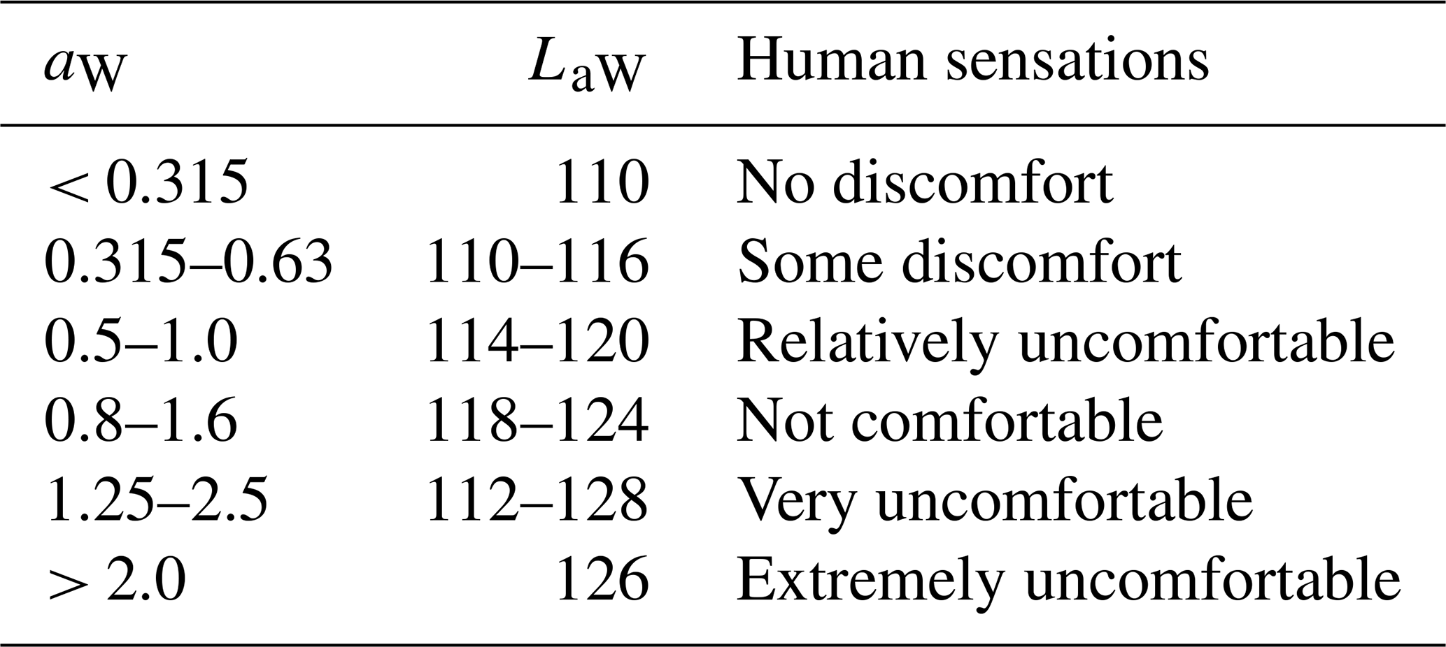
The aforementioned RMS values of acceleration and the total weighted vibration level both influence the subjective comfort perception of passengers. However, different individuals exhibit slight variations in their sensitivity to vibrations. Therefore, it is necessary to determine values that are suitable for most people. The relationship between the vibration perception of the majority of people and the two indicators mentioned above is shown in Table 3.
Table 3The relationship between human subjective perception and LaW and aW.
Two test points were determined: M01, below the magnetic levitation spring; and M02, above the magnetic levitation spring.
The vehicle is driven at different speeds on various roads or surfaces with different obstacles. Using the installed sensors, data such as vibration displacement, frequency, and vibration velocity are measured and recorded.
5.2 Testing on different road types
To investigate the stability of the magnetic levitation spring during the operation of a small vehicle, field tests were conducted under various road conditions. Measurements of the vehicle's vibration displacement, frequency, and amplitude were taken. Utilizing these data, the vehicle's driving state can be assessed according to ride comfort evaluation metrics. Furthermore, a functional electric vehicle prototype was constructed, incorporating key components such as magnetic levitation springs, hub motors, a battery box, a chassis, seats, and a control console.
Two testing points were identified: M01, located below the magnetic levitation spring; and M02, located above the magnetic levitation spring.
Two types of road surfaces were selected: a regular asphalt road and a parking lot surface. The regular asphalt road's smoothness meets the national standards for first-class highways. In contrast, the parking lot surface is uneven, with uniformly distributed protrusions, meeting the experimental requirements for special roads. Observe the changes in each test target as the vehicle accelerates, runs steadily, and decelerates to a stop within 1 min. The wheel hub motor speed was set to 40 RPM, equivalent to a straight-line speed of 1.34 m s−1 for the vehicle. Data from points M01 and M02 on the regular road are shown in Fig. 9, and data from the special road are shown in Fig. 10. The three-axis acceleration data are shown in Figs. 11 and 12.
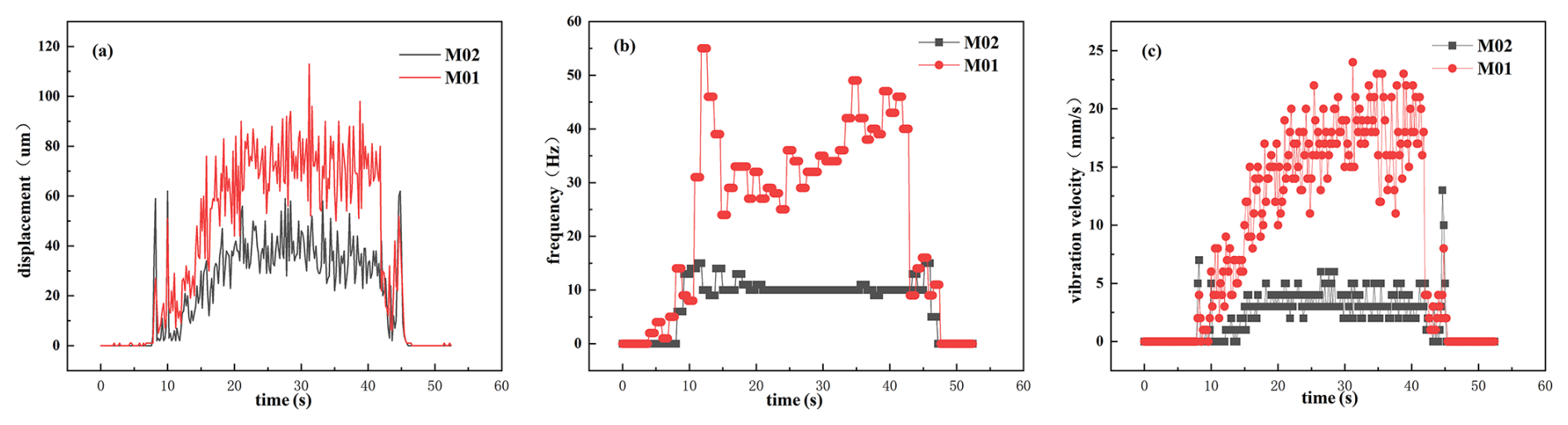
Figure 9Regular asphalt road: (a) vibration displacement, (b) vibration frequency, (c) vibration velocity curves.
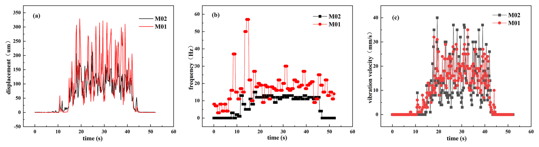
Figure 10Parking lot surface: (a) vibration displacement, (b) vibration frequency, (c) vibration velocity curves.
As shown in Figs. 9 and 10, the vibration displacement, frequency, and velocity curves at the M01 testing point are all lower than those at the M02 testing point. Additionally, the curves at the M02 testing point exhibit an overall trend toward a stable state.
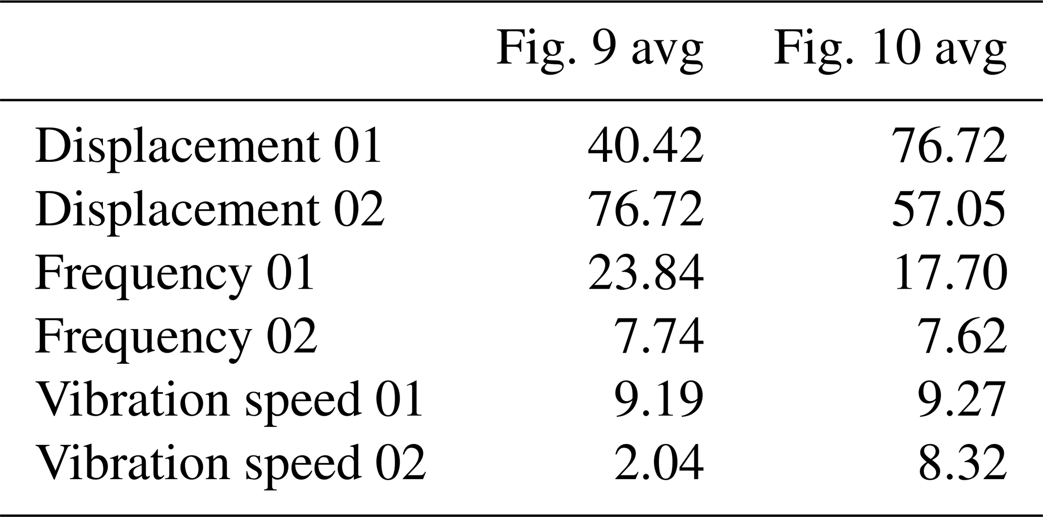
The average values of vibration displacement, frequency, and velocity from Figs. 9 and 10 are summarized in Table 4. The data indicate that the magnetic levitation spring significantly reduces vibration displacement, frequency, and velocity. On normal roads, the reductions are 46.82 %, 67.53 %, and 77.80 %, respectively, while on special roads, the reductions are 25.23 %, 58.82 %, and 10.24 %, respectively. This demonstrates that the magnetic levitation spring effectively reduces vibrations on both types of road, with particularly outstanding performance on normal roads. Furthermore, the application of the magnetic levitation spring in vehicles also shows a clear vibration-damping effect, with its performance aligning well with the original design intent.
Table 4Average vibration displacement, frequency, and speed on different roads.
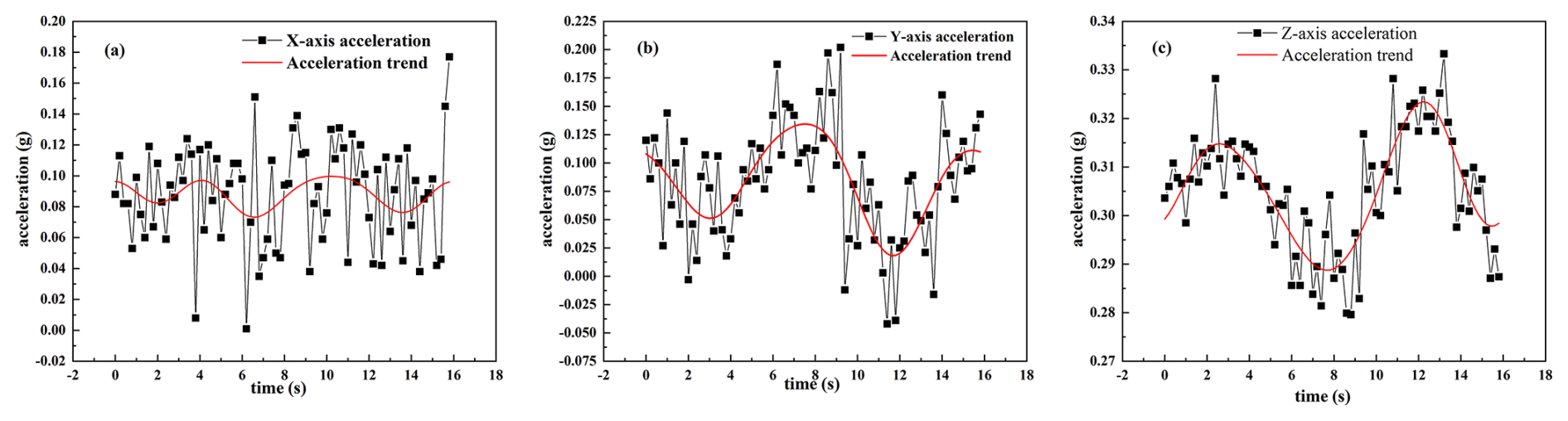
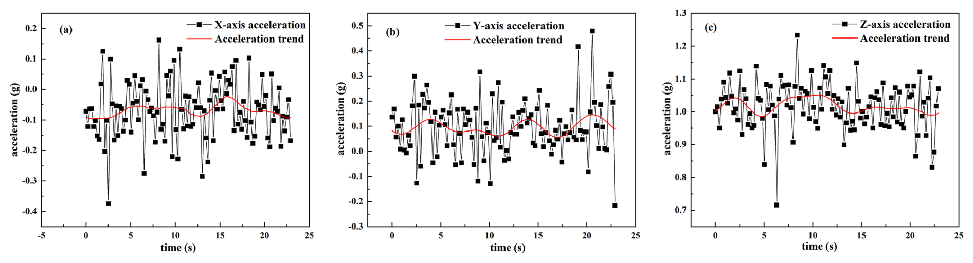
The triaxial acceleration measurements under these conditions are shown in Figs. 11 and 12. To obtain the overall trend of the acceleration curves, filtering operations were applied to remove high-frequency signals, allowing for subsequent analysis to be performed using the trend curves.
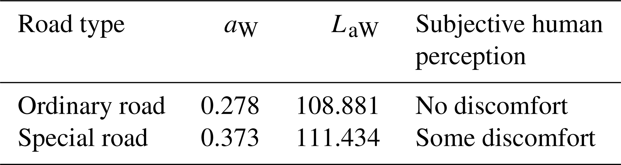
The triaxial accelerations are shown in Figs. 11 and 12. To extract the overall trend of the acceleration curves, a filtering process was applied to remove high-frequency signals, resulting in the trend curves shown as red lines in the figures. Figures 11a, b, c and 12a, b, c correspond to the x-, y-, and z-axis accelerations, respectively. The red curves depict the general trend of the acceleration data. Using Eqs. (16) and (17), the RMS acceleration values and weighted vibration levels for normal and special roads were calculated, as shown in Table 5. A comparative analysis shown in Table 3 indicates that while driving on normal roads, no significant discomfort is experienced. However, some discomfort sensations may occur on special roads.
When the vehicle is driving on special roads, the vibration-damping effect of the magnetic levitation spring on vibration displacement is not ideal, with noticeable lag observed at certain specific points. However, all test groups exhibited excellent performance in terms of vibration frequency and velocity, with the curves at point M02 being significantly lower than those at point M01. This indicates that the magnetic levitation spring demonstrates strong performance in reducing vibration velocity and frequency, and the overall structure aligns well with the design requirements.
-
A design method for magnetic levitation springs was proposed and subjected to numerical analysis, simulation, and experiment; the results showed that the repulsive force of the magnetic levitation spring decreases exponentially with an increase in the distance between the permanent magnets. The trend of the repulsive force curves from calculations, simulations, and experiments matched closely, with the maximum deviation between the experimental and simulation values being 41.3 N (error not exceeding 10.3 %) and the maximum deviation between the experimental and calculated values being 131.7 N (error not exceeding 32.9 %). Most errors occurred at points where the magnet distance was relatively large.
-
Damping ratio experiments showed that results indicate that compared with the non-conductor shell, the damping ratio of the magnetic levitation spring increased by about 103.69 % when a conductor shell was added. The conductor shell significantly hinders acceleration transmission efficiency, effectively resisting oscillations and converting energy.
-
Field tests of the magnetic levitation spring on a small vehicle showed that, at the M02 test point compared to the M01 test point, vibration displacement, frequency, and velocity were reduced by 46.82 %, 67.53 %, and 77.80 %, respectively, on normal roads, and by 25.23 %, 58.82 %, and 10.24 %, respectively, on special roads. The magnetic levitation spring demonstrated good vibration-damping effects on both normal and special roads. On normal roads, subjective human perception indicated no discomfort, while on special roads, some discomfort was noted. Numerical and experimental analyses validated the effectiveness of the magnetic levitation spring, providing a theoretical foundation for its application.
The datasets generated and supporting the findings of this article are obtainable from the corresponding author upon reasonable request.
The authors' contributions are as follows. MX and HW proposed methods and participated in the revision of the paper. JW perfected the methodology and wrote most of the paper. ZZ assisted with the simulation. YW and XW assisted with the experimental part. HW checked and revised the paper. All authors read and approved the final article.
The contact author has declared that none of the authors has any competing interests.
Publisher's note: Copernicus Publications remains neutral with regard to jurisdictional claims made in the text, published maps, institutional affiliations, or any other geographical representation in this paper. While Copernicus Publications makes every effort to include appropriate place names, the final responsibility lies with the authors. Views expressed in the text are those of the authors and do not necessarily reflect the views of the publisher.
The authors thank the editors and reviewers for their efforts.
This research has been supported by the Foundation for Innovative Research Groups of the National Natural Science Foundation of China (grant no. 12205004); the Anhui Polytechnic University and Jiujiang District Industrial Synergy Innovation Special Fund (grant no. 2022cyxtb8); the Key Laboratory of Intelligent Equipment and Technology in Mines of Anhui Province, Anhui University of Science and Technology (grant no. 201901004); the Anhui Intelligent Mine Technology and Equipment Engineering Research Center (grant no. AIMTEFL202201); the Start-up Fund for Scientific Research (grant no. 2021YQQ028); the 2024 Key Project of the Excellent Young Teachers Training Program (grant no. YQZD2024018); the 2024 Anhui Province Postdoctoral Science Foundation (grant no. 2024C976); the open projects of the Joint Key Laboratory of Intelligent Equipment Quality and Reliability in Anhui Province (grant nos. IEQRKL2409 and IEQRKL2404); the Intelligent Sensing and Instrumentation Modern Industry College Project (grant no. 2024xdcyxy05); and the Anhui Province Key Laboratory of Advanced Numerical Control & Servo Technology (grant no. XJSK202506).
This paper was edited by Liangliang Cheng and reviewed by three anonymous referees.
Ahmat, M., Liu, F., and Qiu, W.: Analysis of friction vibration characteristics of the end face of a T-slot sealing ring under thermal deformation, Proceedings of the Institution of Mechan-ical Engineers, Part E: Journal of Process Mechanical Engineering, 09544089241288023, https://doi.org/10.1177/09544089241288023, 2024.
Bei, S. Y. and Huang, C.: Hybrid Sensor Network Control of Vehicle Ride Comfort, Handling, and Safety with Semi-Active Charging Suspension, Int. J. Distrib. Sens. Net., 16, https://doi.org/10.1177/1550147720904586, 2020.
Gori, N., Simonelli, C., and Musolino, A.: Design and Optimization of a Permanent Magnet-Based Spring–Damper System, Actuators, 12, 291, https://doi.org/10.3390/act12070291, 2023.
Kim, Y. C., Lee, H. W., and Hu, J. W.: Experimental Performance Evaluation of Elastic Friction Damper, Case Stud. Const. Mat. J., 18, 18, https://doi.org/10.1016/j.cscm.2023.e01823, 2023.
Li, M. M.: Study on Magnetic Properties and Structure of NdCeFeB Nanomagnetic Materials, Inner Mongolia University of Science and Technology, https://doi.org/10.27724/d.cnki.gnmgk.2023.000114, 2023.
Liao, H., Liu, Y., Li, H., and Zhao, X.: Quantitative prediction of wear failure based on dissipative methodology under dry frictio, Wear, 546, 205331, https://doi.org/10.1016/j.wear.2024.205331, 2024.
Liu, J. X., Wang, Y., and Liu, Z. F.: Design of Dual Magnetorheological Dampers Suspension for Electric Wheel Vehicles, Mech. Des. Manuf., 11, 207–210, https://doi.org/10.3969/j.issn.1001-3997.2020.11.052, 2020.
Liu, Y. Q.: Study on Composite Buffer Characteristics of Permanent Magnet-Structure Hydraulic Cylinder Based on Halbach Array, Kunming University of Science and Technology, https://doi.org/10.27200/d.cnki.gkmlu.2019.001769, 2019.
Novak, M., Cernohorsky, J., and Kosek, M.: Simple Electro-Mechanical Model of Magnetic Spring Realized from FeNdB Permanent Magnets, Procedia Engineering, 48, 469–478, https://doi.org/10.1016/j.proeng.2012.09.541, 2012.
Robertson, W., Cazzolato, B., and Zander, A.: Theoretical Analysis of a Non-Contact Spring with Inclined Permanent Magnets for Load-Independent Resonance Frequency, J. Sound. Vib., 331, https://doi.org/10.1016/j.jsv.2011.11.011, 2012.
Sacco, E. and Moon, S. K.: Modelling the Stiffness of Plastic Springs Manufactured via Additive Manufacturing, J Eng Manuf, 236(5), 486-497, https://doi.org/10.1177/09544054211038282, 2022.
Shen, P., Zhou, D., and He, T. Z.: Review and Prospect of Additive Manufacturing Technology for Rare Earth Permanent Magnet Materials, Metallic Functional Materials, 30, 1–9, https://doi.org/10.13228/j.boyuan.issn1005-8192.20220147, 2023.
Sun, F. L., Zhao, W. B., and Du, Z. Y.: Study on Mechanical Characteristics of Variable Stiffness Mechanism Based on Permanent Magnetic Spring and Swing Rod, Chinese Journal of Construction Machinery, 21, 194–198, https://doi.org/10.15999/j.cnki.311926.2023.03.016, 2023.
Wang, S., Shen, D. M., and Yang, J. G.: Experimental Study on Suppressing Vertical Condenser Pump Vibration with Electromagnetic Eddy Current Damper, Noise and Vibration Control, 43, 247–252, https://doi.org/10.3969/j.issn.1006-1355.2023.06.039, 2023.
Wang, Z.: Taking BYD as an Example: Analysis of Key Technologies and Development Trends in China's New Energy Vehicle Industry, Automotive Maintenance Technicians, https://doi.org/10.3969/j.issn.1671-279X.2024.06.066, 2024.
Yang, X. P.: Study on Braking Characteristics of Crane Mechanism Based on Permanent Magnet Eddy Current Brake, Southwest Jiaotong University, https://doi.org/10.3969/j.issn.1001-3997.2017.12.016, 2017.
Ye, L. Z., Liu, Y. P., and Cao, M. P.: Analysis and Experimental Study on Braking Characteristics of Permanent Magnet Eddy Current Retarder, Journal of Beijing University of Technology, 44, 837–842, https://doi.org/10.11936/bjutxb2017040038, 2018.
Zhao, Y. Q., Deng, Y. J., Lin, F., Zhu, M. M., and Xiao, Z.: Transient dynamic characteristics of a non-pneumatic mechanical elastic wheel rolling over a ditch, Int J Auto Tech, 3(19): 499–508, https://doi.org/10.1007/s12239%E2%88%92018%E2%88%920048%E2%88%926, 2018.
Zhao, F. T. and Wang, S. W.: Calculation of Force action between permanent magnet, Journal ofJiLin Institute of Technology, 12(1), 9–13, https://doi.org/10.15923/j.cnki.cn22-1382, 1991.
Zhen, Y. L.: Design of Energy-Feeding Shock Absorption Module in New Energy Electric Vehicle, Integrated Circuit Applications, 41, 116–117, https://doi.org/10.19339/j.issn.1674-2583.2024.02.047, 2024.
- Abstract
- Introduction
- Structure and working principle of magnetic levitation spring
- Numerical analysis of the repulsive force and damping ratio of magnetic levitation springs
- Bench tests and results analysis
- Full-vehicle test and results analysis
- Conclusion
- Data availability
- Author contributions
- Competing interests
- Disclaimer
- Acknowledgements
- Financial support
- Review statement
- References