the Creative Commons Attribution 4.0 License.
the Creative Commons Attribution 4.0 License.
 | 03 Dec 2025
Coupled gas–solid flow dynamics and particle capture mechanisms in a sweeping–suction cleaning system
Yaozong Xu
Chao Gong
Yajuan Chen
Bixin Cai
Jinduo Liu
Jiabao Pan
To investigate the coupling mechanisms between operational parameters and particle transport behavior in the sweeping–suction system of a road sweeper, a computational fluid dynamics–discrete element method (CFD–DEM)-coupled numerical model was developed based on a specific sweeper configuration. The model captures the dynamic response of particles under the combined effects of disk-brush-induced turbulence and suction nozzle negative pressure. Parametric studies were conducted to evaluate the influence of brush angle, rotational speed, and suction pressure on the cleaning efficiency and migration trajectories of particles with varying sizes. The simulation results indicate that optimal cleaning performance is achieved when the brush angle is within the β3–β5 range, the rotational speed is between 130–160 rev min−1, and the suction pressure is maintained between −2.6 and −2.8 kPa. Flow field analysis reveals a gradual spatial coupling between the rotational airflow induced by the brush and the suction field, forming a stable high-speed adsorption zone. Smaller particles are more susceptible to deviations from the ideal collection path due to the influence of flow non-uniformity. The proposed CFD–DEM framework demonstrates high accuracy and applicability in resolving gas–solid interactions and particle motion in sweeping operations, offering theoretical guidance for parameter optimization and structural design of road cleaning systems.
- Article
(17963 KB) - Full-text XML
- BibTeX
- EndNote


With the acceleration of urbanization, issues such as vehicle exhaust emissions, construction dust, and road debris have become increasingly severe (Ma et al., 2025; Lundberg et al., 2020; Desye et al., 2025; Das and Wiseman, 2024). Sweeping-and-suction-type cleaning vehicles, as highly efficient environmental sanitation equipment, have been widely adopted in urban cleaning operations (Rienda and Alves, 2021; Wang et al., 2024a; Zhang et al., 2024b; Beauchemin et al., 2021). These devices achieve ground debris removal through the synergistic action of brush agitation and suction nozzle negative pressure, with their operational performance largely dependent on the particle transport characteristics within the sweeping and suction system (Wang et al., 2025; D'Andrea et al., 2022; Scott et al., 2022; Jeong et al., 2022). Currently, most studies remain at the level of single-structure optimization and parameter experiments, lacking a systematic understanding of particle movement paths, response patterns, and the coupled effects of key parameters. Therefore, in-depth research into the transport mechanisms of particles within the sweeping and suction system holds significant theoretical and engineering value for improving cleaning efficiency, optimizing operational parameters, and achieving fundamental performance enhancements of the equipment (Bchir et al., 2022; Fayzullayevich et al., 2022a, b; Liu et al., 2023).
With the improvement of simulation computing capability and intelligence level, numerical simulation technology has been widely applied in the optimization design and performance analysis of industrial equipment (Zhang et al., 2024a; Sun et al., 2025). Zhou et al. (2025) proposed a novel W-type blow-and-suck dust collector and systematically analyzed the influence of its structural and operational parameters on dust removal performance using computational fluid dynamics (CFD) numerical simulation methods. The results indicated that the device could achieve over 95 % dust removal efficiency under optimal parameter combinations. Pan et al. (2023) used CFD to analyze the impact of suction port structural parameters on sweeping performance and introduced a whale optimization algorithm to determine the optimal structural configuration. The optimization results showed that this method has significant advantages in reducing airflow loss and shortening particle residence time (Ye et al., 2022a, b). Vanegas-Useche et al. (2015) conducted removal experiments on different types of debris (including medium-sized gravel, small particles, fine particles, wet thin debris, and compacted debris) on a brush washing test bench, finding that vibrating disk brushes exhibit superior cleaning performance in removing adhesive particles and wet debris. Yong et al. (2024) developed a cleaning robot integrating scraping, crushing, sweeping, and vacuuming functions for large-scale tank cleaning. They optimized the vacuum system structure and nozzle parameters through simulation, and experimental validation demonstrated a significant reduction in dust leakage on both sides of the nozzle, improved system performance, and validated the reliability of the simulation. Parween et al. (2020) developed a sweeping and vacuuming module integrated into a cleaning robot and analyzed its internal flow field distribution using CFD. Experimental validation results showed that the module significantly improved cleaning efficiency. Ding et al. (2024) used CFD methods to construct a dual-airflow nozzle flow field model, systematically analyzing the impact of cavity structure parameters on negative-pressure airflow field characteristics. Through response surface optimization, the optimal structural combination was determined, providing theoretical support and design references for the structural optimization of complex cavity pickup devices.
Research has found that the computational fluid dynamics–discrete element method (CFD–DEM) method can effectively characterize particle motion behavior in gas flow environments and reveal the motion patterns of particles in flow fields. For example, Yang et al. (2024) analyzed a Z-type pneumatic separator to reveal that high-speed gradient gas flows and turbulent structures can enhance the separation efficiency of metal and non-metal particles in thermal decomposition residues of waste circuit boards, and they combined CFD and DEM methods to achieve high-precision simulation of separation behavior. Zhou et al. (2024) employed a four-way-coupled CFD–DEM method to elucidate the mechanism of state transition and pressure characteristics of gas–solid two-phase flow in horizontal pipes, clarifying the evolution patterns of particle distribution and transport flow patterns under different apparent gas velocities. El-Emam et al. (2019)+ systematically optimized the geometric structure of a counter-current cyclone separator and conducted numerical simulations, verifying the significant improvement in separation efficiency and cleaning performance due to the inlet height, providing theoretical support and design basis for efficient separation in agricultural and industrial applications. El-Emam et al. (2019) conducted a combined CFD–DEM simulation of the fluidization separation process of sugarcane bagasse particles, confirming that this modeling strategy can effectively predict actual separation behavior and has the potential to be extended to processes such as biomass drying, pyrolysis, and gasification.
Although previous studies have made significant progress in investigating the local flow field around brush disks or suction nozzles and the gas–solid coupling within individual components, joint quantitative research considering the interactions among brush disks, suction nozzles, and ground particles at the system level remains relatively scarce. To address this gap, this study employs a CFD–DEM approach to develop an integrated numerical model encompassing disk brushes, suction nozzles, and ground particles. This model reveals the synergistic mechanisms between sweeping and suction operations at the system level and their impact on particle transport characteristics. Compared to traditional studies, the innovations of this work include the following: firstly, achieving multi-physics coupling calculations at the system scale for the interaction between the brush, suction nozzle, and ground particles, enabling accurate analysis of multiple interactions including particle–particle collisions, particle–airflow interactions, and particle–wall interactions; secondly, quantitatively revealing the synergistic effects between the brush-guided flow field and suction nozzle extraction, along with their influence on particle migration paths and capture efficiency. This research breaks away from the conventional approach of analyzing either the brush or suction nozzle in isolation. It holds significant theoretical and practical value for deepening the understanding of gas–solid two-phase flow behavior in sweep–suction cooperative cleaning processes and for optimizing cleaning operation parameters.
2.1 Physical model
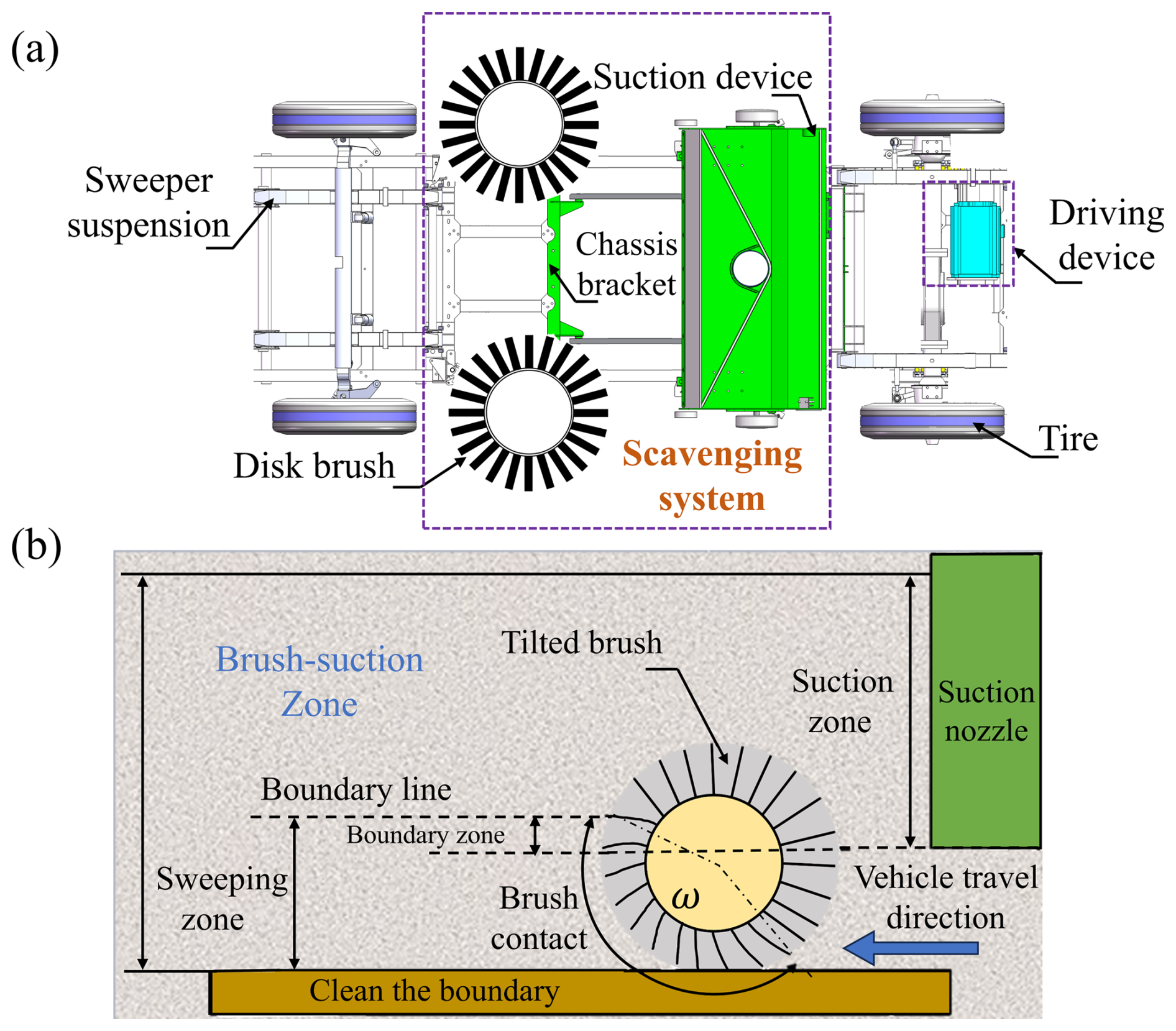
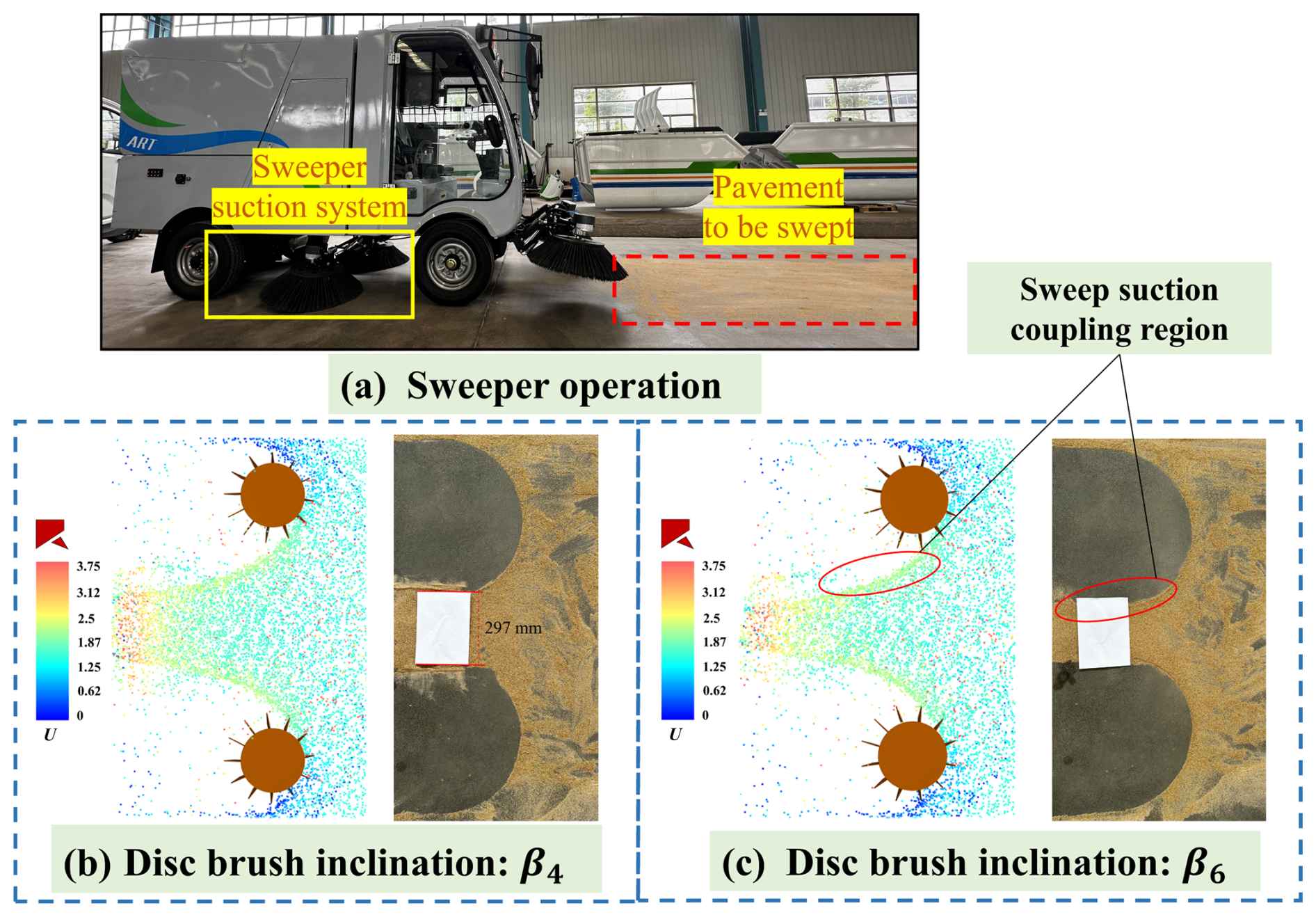
Road sweeping vehicles are typically modified from standard Class II vehicle chassis (Cho et al., 2021), as shown in Fig. 1a. During sweeping operations, the brush disks mounted on both sides of the vehicle body maintain contact with the road surface at specific angles and rotation directions. Through mechanical rotation, solid waste from both sides and corners of the road surface is concentrated toward the center and guided into the effective working area of the suction nozzle. The suction nozzle uses negative-pressure airflow generated by a fan to suck in debris particles, which are then transported through a closed pipeline system into the dust collection box. To enhance the synergistic effect of sweeping and suction, the effective contact range of the brush disks is designed as a fan-shaped trajectory, as shown in Fig. 1b, and partially overlaps with the suction nozzle's pickup area in geometric structure, thereby improving debris collection efficiency and reducing residual rates.
This paper focuses on the evolution of the internal flow field characteristics of the sweeping and suction system of road sweeper vehicles. Based on the structural configuration of the sweeping device and the dynamic characteristics of the suction nozzle and brush disk, a complete sweeping and suction flow domain and brush disk parameter diagram is constructed, as shown in Fig. 2.
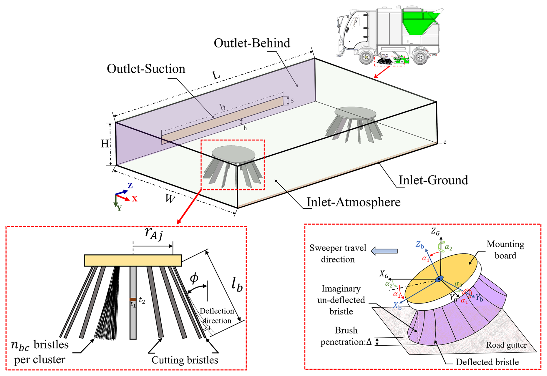
To ensure simulation accuracy while reasonably controlling computational resource consumption, moderate idealization was applied to the geometric characteristics of the disk brush bristles and operational conditions during model construction:
-
The brush bundle of the disk brush, composed of numerous bristles, is assumed to form a single rectangular structure.
-
The disk brush bristles are assumed to undergo no elastic deformation upon contact with particles.
-
Surface particles are assumed to possess a certain initial vertical distribution height c.
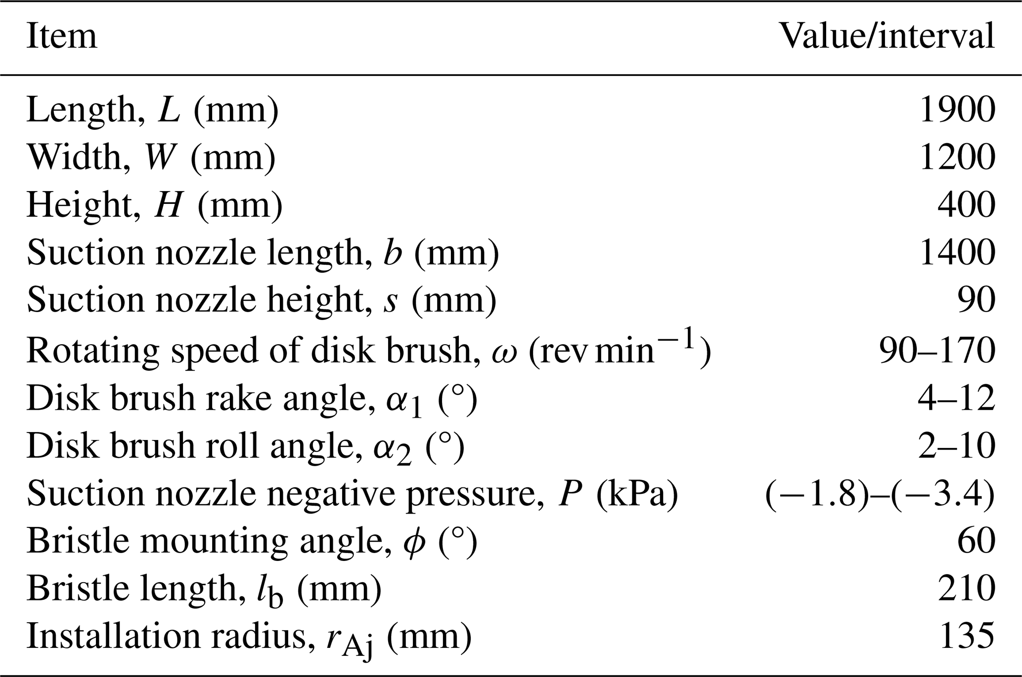
This simplification strategy effectively reduces model complexity without significantly compromising physical realism. Table 1 summarizes the developed simulation model structure and main brush parameters.
2.2 CFD–DEM model
2.2.1 CFD modeling
In the CFD–DEM-coupled computational method, the fluid is treated as a continuous medium, and its flow characteristics are solved using the incompressible unsteady Navier–Stokes equations in the Euler coordinate system. The continuity equation and momentum conservation equation for the fluid are as follows (De Almeida et al., 2019; Wang et al., 2024b; Zhang et al., 2025; Ma et al., 2024):
where ρf, ξ, and μf represent the density, volume fraction, and velocity of the fluid, respectively; P is the gas-phase pressure; g is the gravitational acceleration; Rf is the viscous stress tensor; t is time; and Fp-f represents the interaction force between the fluid and particles. In this study, this interaction force term can be calculated using the following equation:
where fp-f,i represents the total fluid force acting on particle i; Vcell denotes the volume of a single grid cell; and kcell denotes the number of particles contained in that grid cell. Additionally, this study employs the k-ε turbulence model to simulate the turbulence characteristics in air by using the following equations:
where k denotes turbulent kinetic energy; ε denotes the dissipation rate of turbulent kinetic energy; ρg denotes the dynamic viscosity of air; μt denotes the turbulent viscosity; vg denotes the kinematic viscosity; ugi denotes the velocity component of air in the Cartesian coordinate system, where g, ; σε=1.2, σk=1 are empirical coefficients; and Gk denotes the turbulent kinetic energy term generated by the average velocity gradient.
2.2.2 DEM modeling
In DEM simulations involving fluid interactions, the complex translational motion (Eq. 6) and rotational motion (Eq. 7) of particle i are modeled based on Newton's second law. Additionally, contact forces within the particle system are described and solved using this law to reflect the dynamic interaction between particles.
where mi denotes the mass of particle i; xi and Φi represent its spatial position and orientation direction, respectively; and Mij denote the contact force and torque exerted by particle j and the wall on particle i, respectively; denotes gravity; denotes the fluid–particle interaction force acting on particle i; denotes the non-contact force exerted on particle i by particle k or other external sources; and Ii denotes the moment of inertia of particle i.
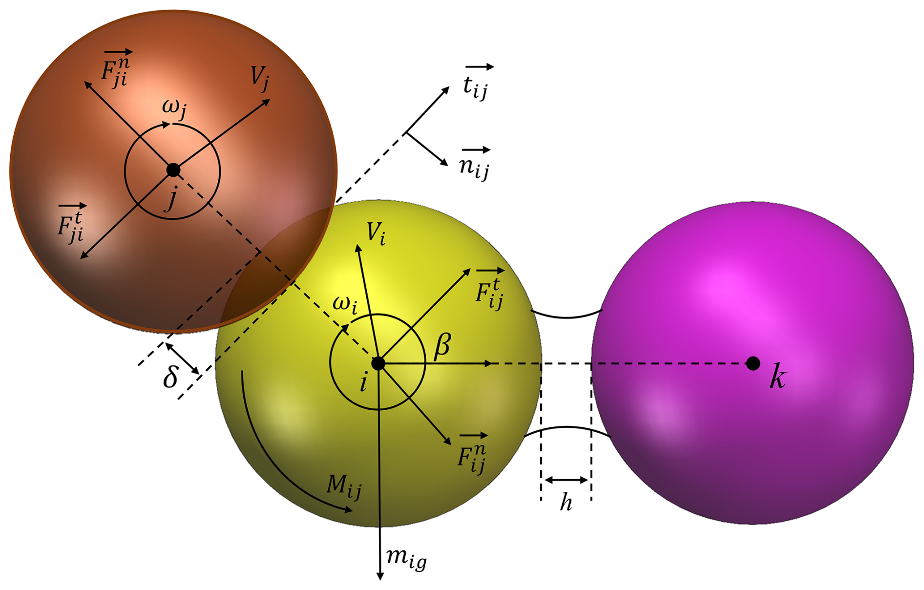
Based on the above particle motion equations, the forces acting on a single particle can primarily be categorized into two types: contact forces, primarily resulting from physical collisions between particles or between particles and walls, and non-contact forces, such as fluid forces, which can be modeled and solved using the discrete element method (DEM). Within this framework, contact forces can be decomposed in a local coordinate system and quantitatively analyzed using Eq. (8).
where and represent the normal contact force and tangential contact force generated when particle i and particle j come into contact with the wall surface, respectively. The schematic diagram in Fig. 3 illustrates the typical contact force vectors, particle overlap displacements, and torque relationships induced by contact behavior in DEM simulations.
The Hysteretic Linear Spring adopted in this study is a contact model based on elastic–plastic theory. The energy dissipation characteristics of this model are independent of relative slip velocity, making it highly adaptable and versatile in multi-particle systems. The following equations provide the mathematical description of the linear hysteretic model:
where and are the normal elastic–plastic contact forces acting on particle i at the current time T and the previous time step T−ΔT, respectively, where ΔT is the time step length; Δδn represents the change in normal overlap during the time step; are the normal overlap values at the current time and the previous time step, respectively; and and represent the normal contact stiffness used during unloading and loading, respectively. The loading stiffness of a particle is calculated as follows (12):
For the contact between two particles or between a particle and a boundary, the loading stiffness and unloading stiffness are defined as follows:
where i and j denote the two contacting particles; w denotes the wall or boundary; Ei and Ew are the Young's moduli of the particle and boundary, respectively; ε is the recovery coefficient; and Z is the particle size or geometric shape.
In interparticle tangential contact modeling, this paper adopts the Linear Spring Coulomb Limit model, which is based on elastic friction theory and can accurately describe the tangential force response behavior caused by relative sliding between particles. Its mechanical response can be expressed by the following formula:
If the tangential force exceeds the limit of μs and , sliding is considered to have occurred during contact. If the tangential force is below μd and , no sliding is considered to have occurred during contact.
2.2.3 CFD–DEM coupling
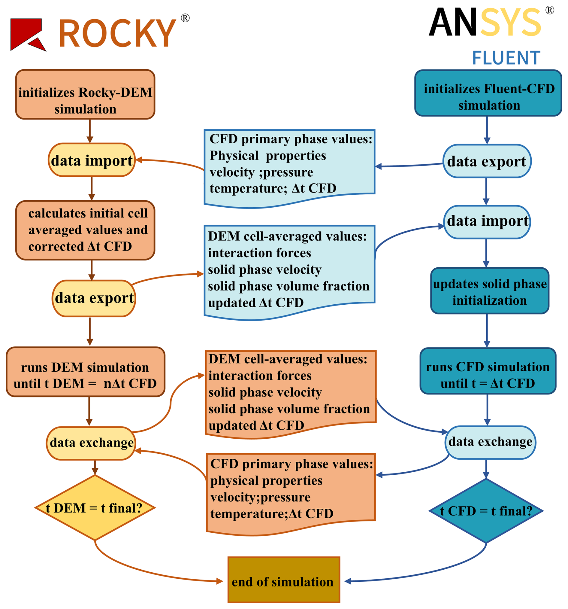
The coupling strategy's workflow and mechanism are shown in Fig. 4. Within the Fluent–Rocky coupling framework, the fluid component employs the traditional continuous medium model in Ansys Fluent®, describing flow behavior through mass conservation, kinetic energy conservation, and energy conservation equations and utilizing the finite volume method (FVM) for numerical solutions, while the solid particle flow is modeled using the discrete element method (Ma et al., 2024; Lvov and Chitalov, 2021). During the coupling calculation process, the fluid time step is typically updated once every 10 DEM time steps. Within each fluid time step, the system solves the interphase coupling terms between the fluid and solid phases, such as the resistance and mass transfer experienced by the particles; meanwhile, the motion attributes of the particles (such as position and velocity) are updated in real time within each DEM time step.
2.3 Boundary condition setup
This study employs a pressure–velocity coupled transient solution model for numerical simulation of the gas–solid two-phase flow field in a sweeper truck. The fluid portion is modeled and simulated using Ansys Fluent® software. In terms of boundary condition settings, the inlet is defined as a velocity inlet with a turbulence intensity of 5 %, the outlet is defined as a pressure outlet, and the system walls are set to no-slip boundary conditions. Since the disk brush is a typical rotating mechanical structure during operation, its motion is handled using a Sliding Mesh model. To ensure computational accuracy, local mesh refinement is applied to the rotating region and its dynamic–static interface. After mesh quality assessment, the orthogonality quality of the resulting mesh is 0.88 and the skewness is 0.20.
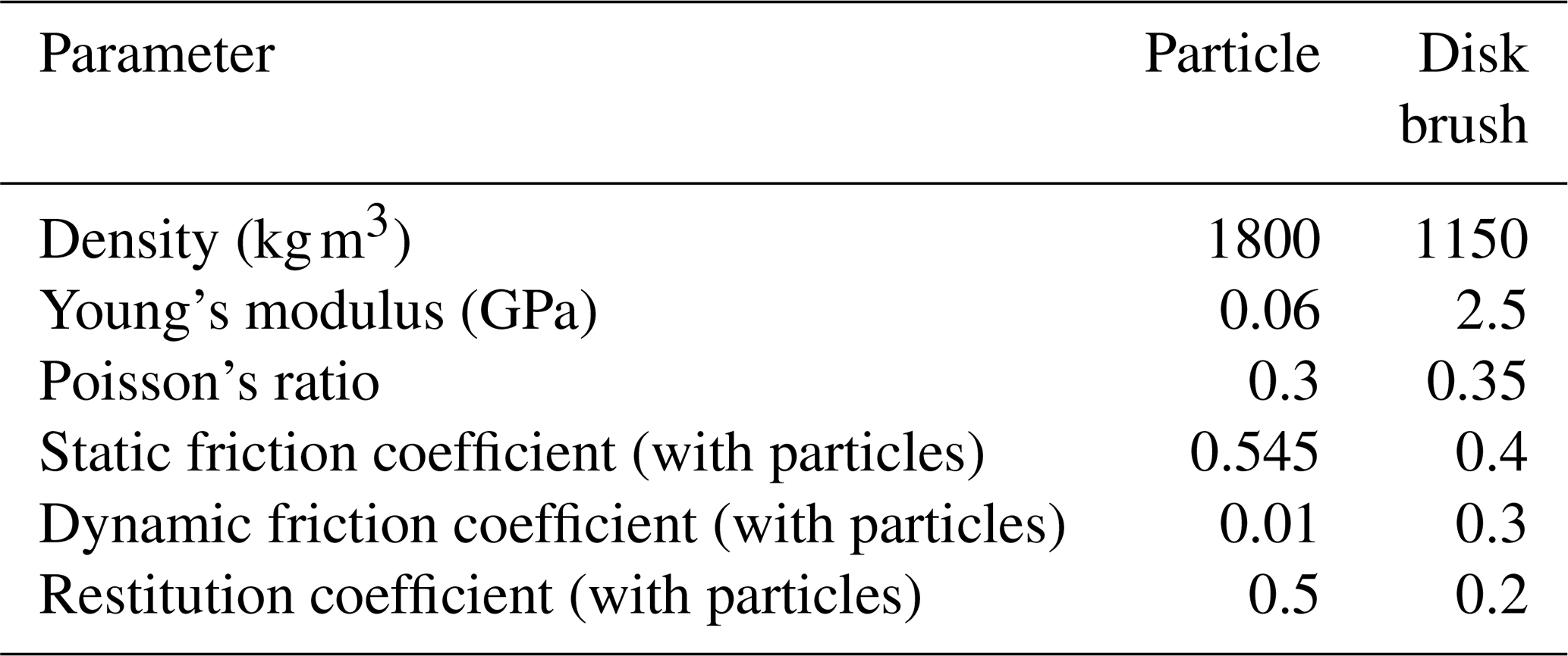
During the Rocky® software setup process, the inlet and outlet boundaries in the model were firstly set as Surface type and designated as the particle inlet and escape outlet, respectively. The particle inlet velocity was set to the sweeper vehicle's travel speed of 3.6 km h−1, and the outlet was set to the coupled negative-pressure value. The main material parameters and their interaction relationships are shown in Table 2.
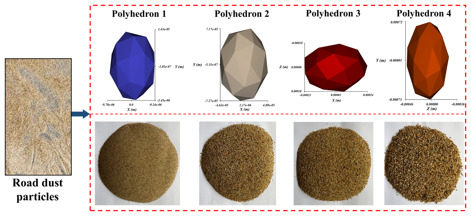
This study employs four representative polyhedral particles with equivalent diameters of 0.02, 0.1, 0.5, and 1 mm, based on screening analyses of dust collected by road sweepers (Wagner et al., 2024). The simulation models particle pickup and capture processes, as shown in Fig. 5, using a 5 s particle incidence duration and an 8 s total computation time. Under these conditions, the model is applicable for analyzing short-term sweeping and suction processes of loose urban road particles (primarily 0.02–1 mm in size, without significant agglomeration or strong adhesion) on dry, level surfaces. Notable limitations include the following: the model disregards kinetic differences between ultrafine particles (<0.02 mm) and coarse debris (>1 mm); particles are simplified as polyhedrons without explicit consideration of cohesive effects like adhesion, electrostatic forces, or capillary action; and boundary conditions primarily assume ideal flat surfaces, excluding complex terrain, wet conditions, or organic binders found in real-world scenarios (Klöckner et al., 2021). Furthermore, the 5 s/8 s timescale primarily reflects short-term pickup and capture processes. Long-term accumulation, repeated actions, and equipment wear require longer-term simulations or experimental validation. In summary, the conclusions presented herein are reliable under the specified conditions but should not be unconditionally extrapolated to all road surfaces and particle types.
2.4 Grid and experimental validation
2.4.1 Grid independence validation
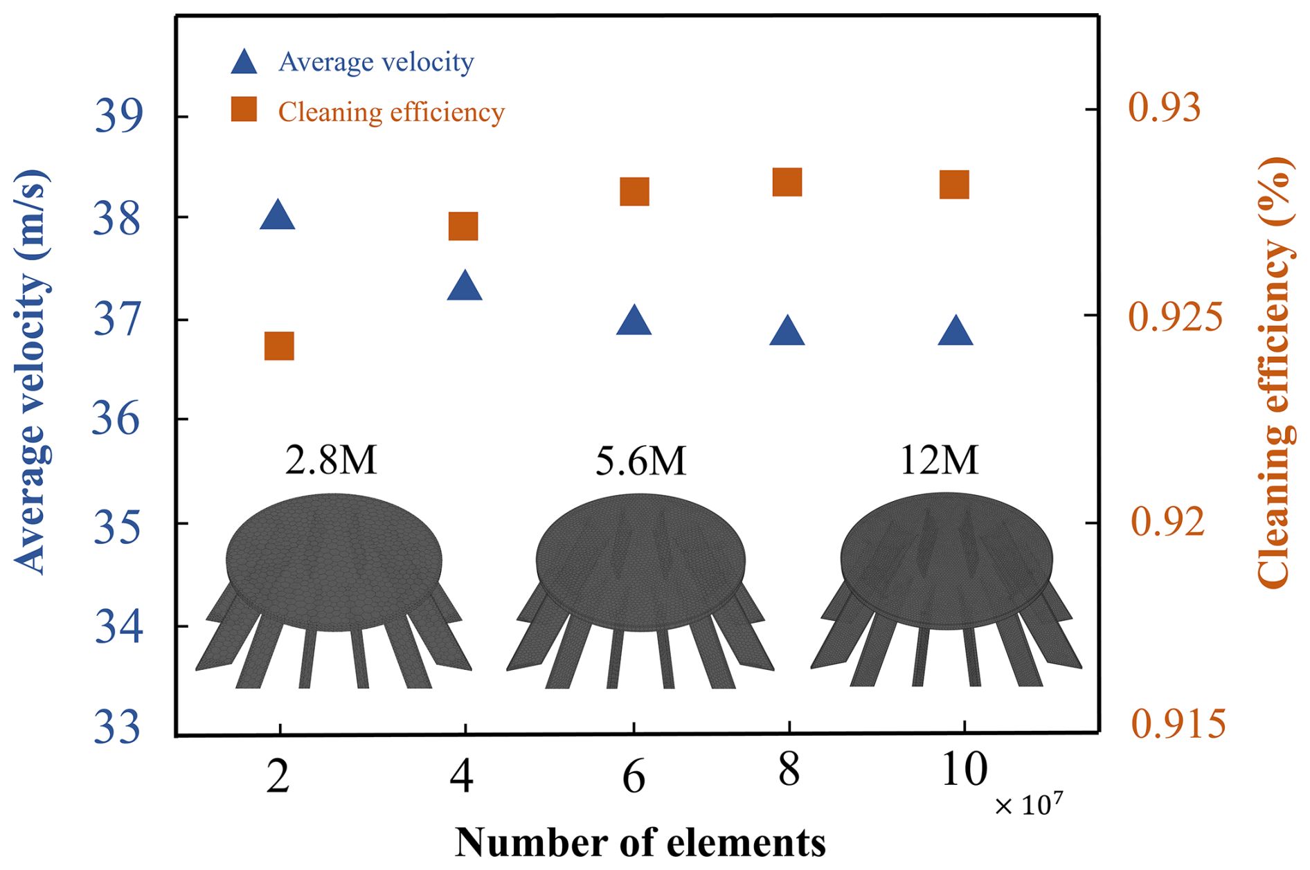
To optimize computational accuracy and efficiency, this paper conducted a comparative analysis of grid schemes at different scales, comprehensively considering factors such as cleaning efficiency metrics and computational resource consumption. Ultimately, the second grid scheme was selected as the final computational model for numerical simulation. The results of the grid independence validation are shown in Fig. 6.
2.4.2 Experimental validation
In order to study the velocity distribution law of the scavenging flow field, the flow velocity in the flow field is dimensionless, and the dimensionless velocity (U) is defined as
where U and u are the nondimensional velocity and actual velocity of the airflow, respectively, and um is the average velocity of the airflow within the flow field.
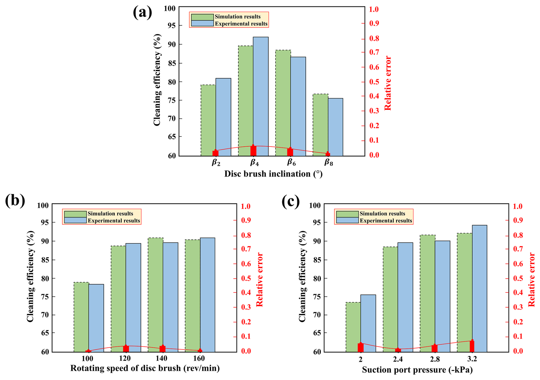
As shown in Fig. 7a, the experiment was conducted under actual field conditions at the company's site, using a self-developed suction-type road sweeper, developed by a certain company. The experiment used particles screened through sieves of different mesh sizes. The particle mass pre-weighed and spread on the test road surface was compared with the final particle mass recovered in the waste collection box to calculate the cleaning efficiency as a performance evaluation metric. Figure 7b and c show the comparison between numerical simulation results and actual vehicle test results under rated operating conditions for different brush angle conditions. The results indicate that the particle trajectories obtained from simulation and experiments exhibit high consistency.
Additionally, Fig. 8 further compares the numerical simulation with the measured cleaning efficiency. The results indicate that the data obtained from both methods show good agreement under multiple operating conditions, with relative errors consistently below 0.1. This validates the effectiveness of the CFD–DEM-coupled model in reconstructing the internal flow field characteristics of the sweeper's suction and sweeping system. The minor discrepancies primarily stem from differences between experimental procedures and numerical modeling: on the one hand, particle distribution and initial conditions exhibit inherent randomness in experiments, while measurements may be influenced by instrument precision and operational variations; on the other hand, numerical calculations employ idealized simplifications for certain boundary conditions and physical processes, failing to fully capture the complexity of real-world scenarios. Overall, these discrepancies do not substantially alter the general trends or quantitative conclusions. Consequently, this methodology can be employed to investigate the influence of operational parameters on particle migration behavior and sweeping performance, demonstrating strong predictive capability and engineering applicability.
To ensure the representativeness and practicality of parameter selection, this paper referenced typical operating conditions of municipal sweeping equipment, manufacturer technical documentation, and relevant literature (Xu et al., 2025) and validated the findings through preliminary experiments. The disk brush inclination angle was selected within the β1–β9 range to cover common operational postures and reflect varying disturbance and centrifugal effects; the rotational speed range of 90–170 rev min−1 balances coarse-particle removal and fine-particle aggregation; and the suction nozzle negative pressure was set between −1.8 and −3.4 kPa, representing an engineering compromise between energy consumption and cleaning efficiency (Wang et al., 2025). These parameter ranges align with actual operational conditions, demonstrating good representativeness and practical value.
3.1 Effect of operational parameters on the cleaning performance of the sweeper
3.1.1 Effect of the disk brush angle on cleaning performance
In the industry, the contact angle between the disk brush and the ground is typically controlled around 120°, achieved by adjusting the forward tilt angle and side tilt angle of the disk brush, as detailed in Table 3.
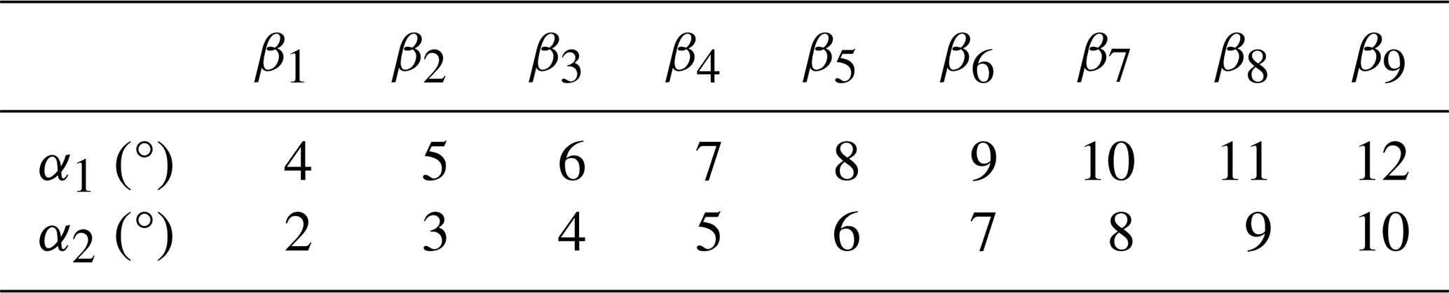
Based on the operational requirements of the studied sweeper, the rated operating conditions are set as follows: disk brush rotational speed ω is 120 rev min−1, suction nozzle negative pressure P is −2.4 kPa, and disk brush angle β is β3. By varying the disk brush angle β, the impact on cleaning performance was analyzed, with results shown in Fig. 9.
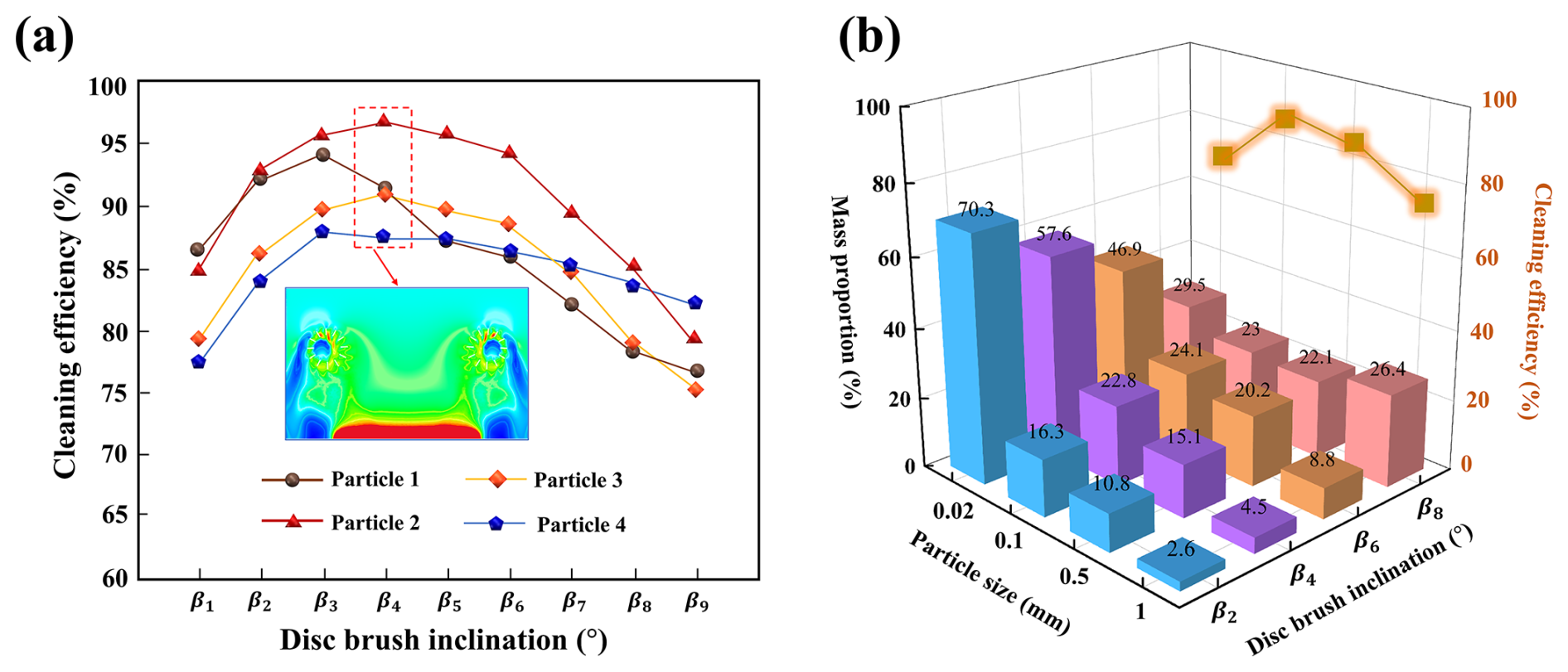
Figure 9Effect of disk brush angle on sweeping performance: (a) changes in cleaning efficiency of particles with different particle sizes at different disk brush angles; (b) comparison of the mass proportion of particles with different particle sizes and their corresponding cleaning efficiency.
As shown in Fig. 9a, as the disk brush angle increases, the cleaning efficiency of particles of different sizes generally follows a trend of first improving and then decreasing. In the velocity contour plot under β4 conditions, the airflow velocity in the outer region of the disk brush is significantly lower than in the inner region. Under the synergistic effect of aerodynamic and mechanical forces, particle movement trends are more likely to concentrate toward the central region, achieving higher particle transport efficiency. Figure 9b further shows the mass percentage of different particles captured at the suction nozzle and the corresponding cleaning efficiency. The results indicate that when the angle is set between β2 and β4, the adsorbed particles are primarily particle 1; as the particle size increases, its mass percentage gradually decreases. When the angle increases to β8, the mass percentage of Particle 4 reaches its maximum value of 26.4 %. This phenomenon primarily arises because, when the tilt angle is too large, fine particles are easily thrown up by the ends of the brush bristles, collide with the base plate and rebound, or are directly swept away from the suction nozzle, leading to a decrease in cleaning efficiency. Therefore, reasonably setting the tilt angle is key to achieving effective particle disturbance and guidance, thereby improving cleaning efficiency.
3.1.2 Effect of disk brush rotational speed on cleaning performance
With the suction nozzle providing a negative pressure of and the disk brush inclination angle set to β3, the effect of varying the disk brush rotational speed ω on cleaning performance was investigated, with results shown in Fig. 10.
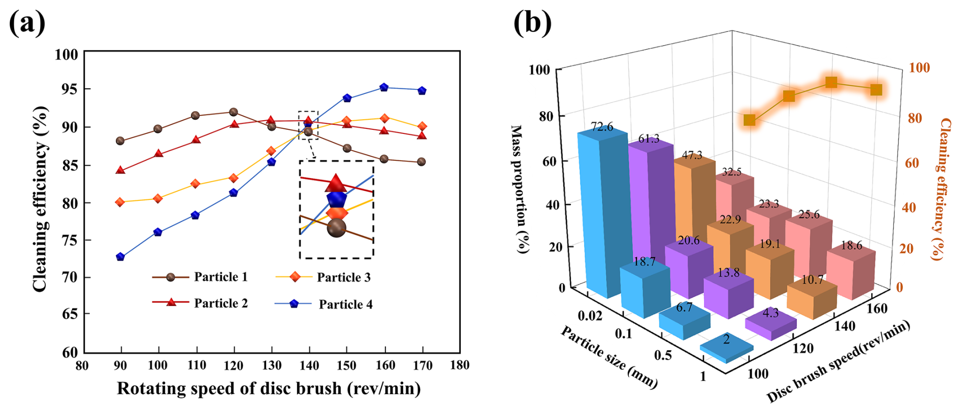
Figure 10Effect of disk brush rotational speed on cleaning performance: (a) changes in cleaning efficiency of particles with different particle sizes at different disk brush angles; (b) comparison of the mass proportion of particles with different particle sizes and their corresponding cleaning efficiency.
As shown in Fig. 10a, as the disk brush rotational speed gradually increases, the cleaning efficiency of particles 1 and 2 significantly improves in the initial stage of speed increase but tends to decrease after reaching a certain speed; meanwhile, the cleaning efficiency of particles 3 and 4 continues to improve with increasing speed. For smaller particles (Particle 1), when the speed reaches approximately 110 rev min−1, the disk brush can provide sufficient disturbance force to achieve effective cleaning. For larger particles (such as Particle 4), as the disk brush speed increases, the tangential force generated strengthens, helping to overcome their inertia and ground adhesion resistance, thereby achieving more effective particle detachment and transport. Further analysis of Fig. 11b reveals that as rotational speed increases, the mass proportion of larger particles captured by the suction inlet gradually rises, while the proportion of finer particles correspondingly decreases.
3.1.3 Effect of suction nozzle negative pressure on cleaning performance
With the disk brush rotational speed set to ω=120 rev min−1 and the disk brush angle set to β3, the effect of varying the suction nozzle negative pressure P on cleaning performance was investigated, with results shown in Fig. 11.
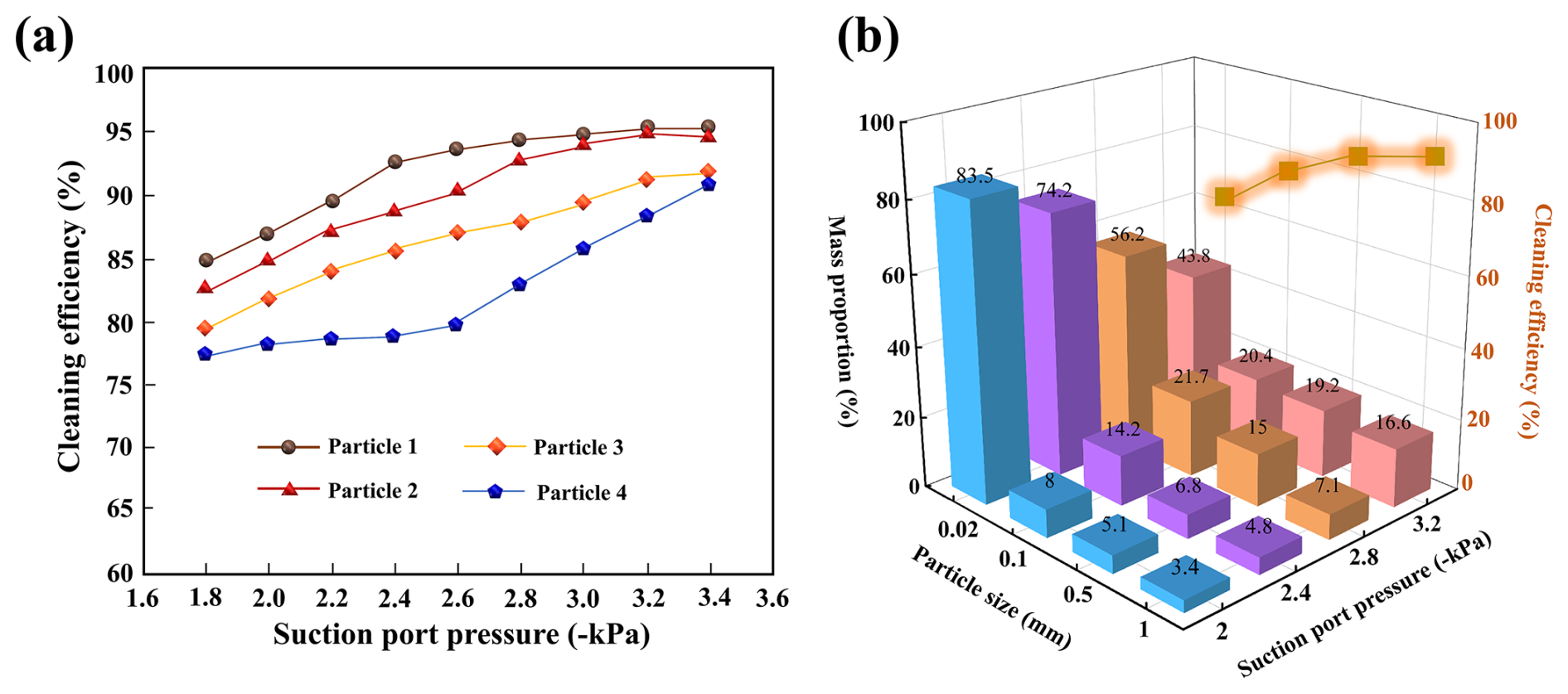
Figure 11Effect of suction nozzle negative pressure on cleaning performance: (a) changes in cleaning efficiency of particles with different particle sizes at different disk brush angles; (b) comparison of the mass proportion of particles with different particle sizes and their corresponding cleaning efficiency.
As shown in Fig. 11a, as the suction nozzle negative pressure increases from −1.8 to −3.4 kPa, the cleaning efficiency of particles of different sizes generally increases. The increase in negative pressure significantly enhances the airflow velocity and adsorption capacity in the suction nozzle area. However, when the negative pressure exceeds −2.8 kPa, the improvement in cleaning efficiency for fine particles (such as Particle 1) tends to saturate, and the improvement for Particle 2 also slows significantly. This is because excessively high negative pressure levels increase flow losses within the flow field, although the enhanced suction force has limited additional disturbance effects on lightweight particles. Figure 11b further reveals the capture characteristics of the cleaning system at different negative pressure levels. Under low-negative-pressure conditions, the system primarily adsorbs smaller particles, demonstrating strong capture capability for fine particles. As negative pressure increases, the mass fraction of medium to large particles (particularly 0.1 and 0.5 mm) significantly increases, indicating that the system's cleaning efficiency for heavier particles improves under high negative pressure, resulting in overall enhanced cleaning performance.
3.2 Analysis of sweeping and suction flow field characteristics
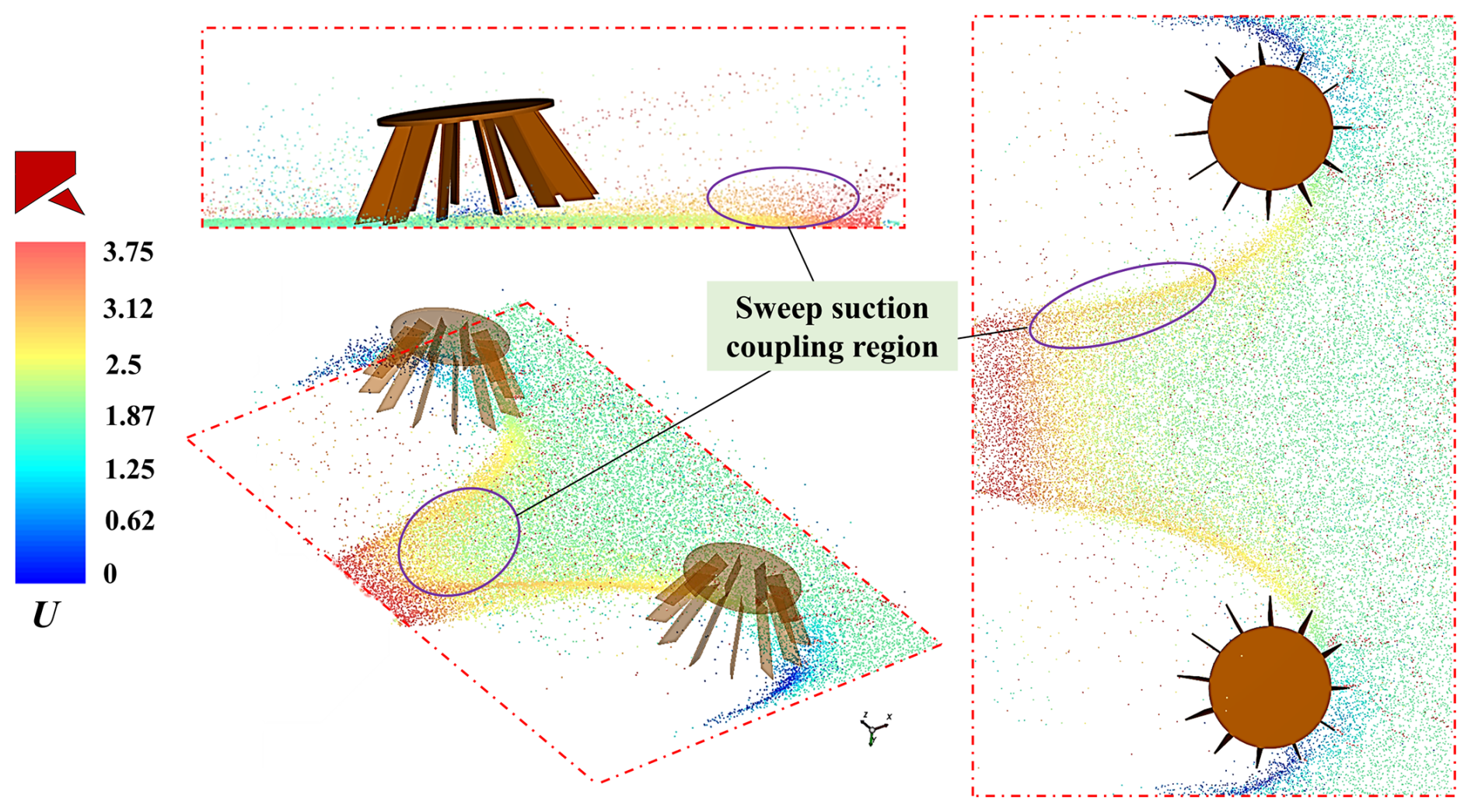
During the sweeping operation, the rotation of the disk brush not only disrupts and transports particles but also forms a specific directional airflow field between the brush and the road surface. Meanwhile, the negative pressure at the suction nozzle induces high-speed airflow to achieve particle adsorption and collection. These two airflow mechanisms are spatially and temporally coupled, jointly determining the particle disruption path, aggregation efficiency, and final adsorption effect. As shown in Fig. 12, the velocity contour map of the sweeping and suction flow field within one rotation cycle of the sweeper is displayed. The sweeping–suction coupling zone is located between the end of the disk brush and the leading edge of the suction nozzle, representing the critical transition zone where particles transition from the mechanical sweeping stage to the aerodynamic adsorption stage. To better study the influence of operational parameters on the sweeping–suction coupling zone, nodes Q, R, and S are set within it to observe changes in airflow velocity in this region.
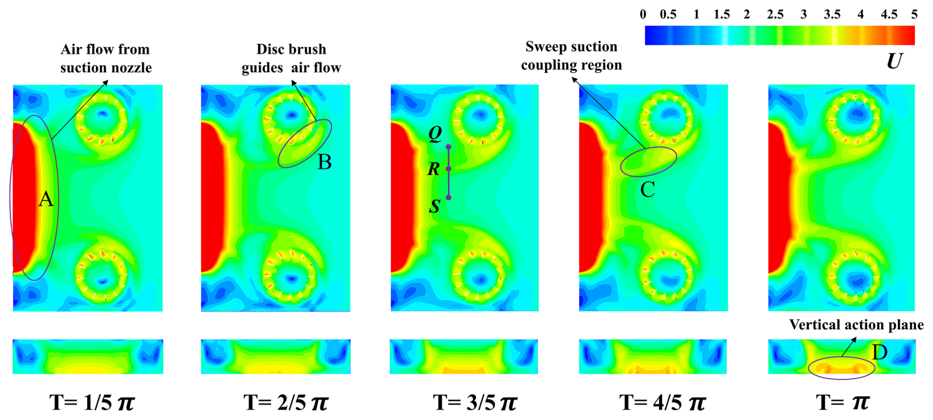
As shown in Fig. 12, the velocity contour map reveals that the airflow diverges after contacting the disk brush, gradually splitting into two primary flow directions. The flow velocity in the front and outer regions of the disk brush is significantly lower than that in the central region of the flow field, and the velocity distribution in the central region exhibits a distinct stepped pattern. At , a distinct high-speed airflow region has formed on the inner side of the front end of the disk brush. This highly ordered high-speed airflow significantly enhances the particle entrainment and transport effects. Further analysis of the vertical cross-sectional velocity contour map of the flow field reveals that, as the operation time increases, a stable and intense high-speed adsorption zone gradually forms in the central region near the suction nozzle, accompanied by a trend of continuously increasing velocity, further enhancing the particle adsorption and cleaning capabilities.
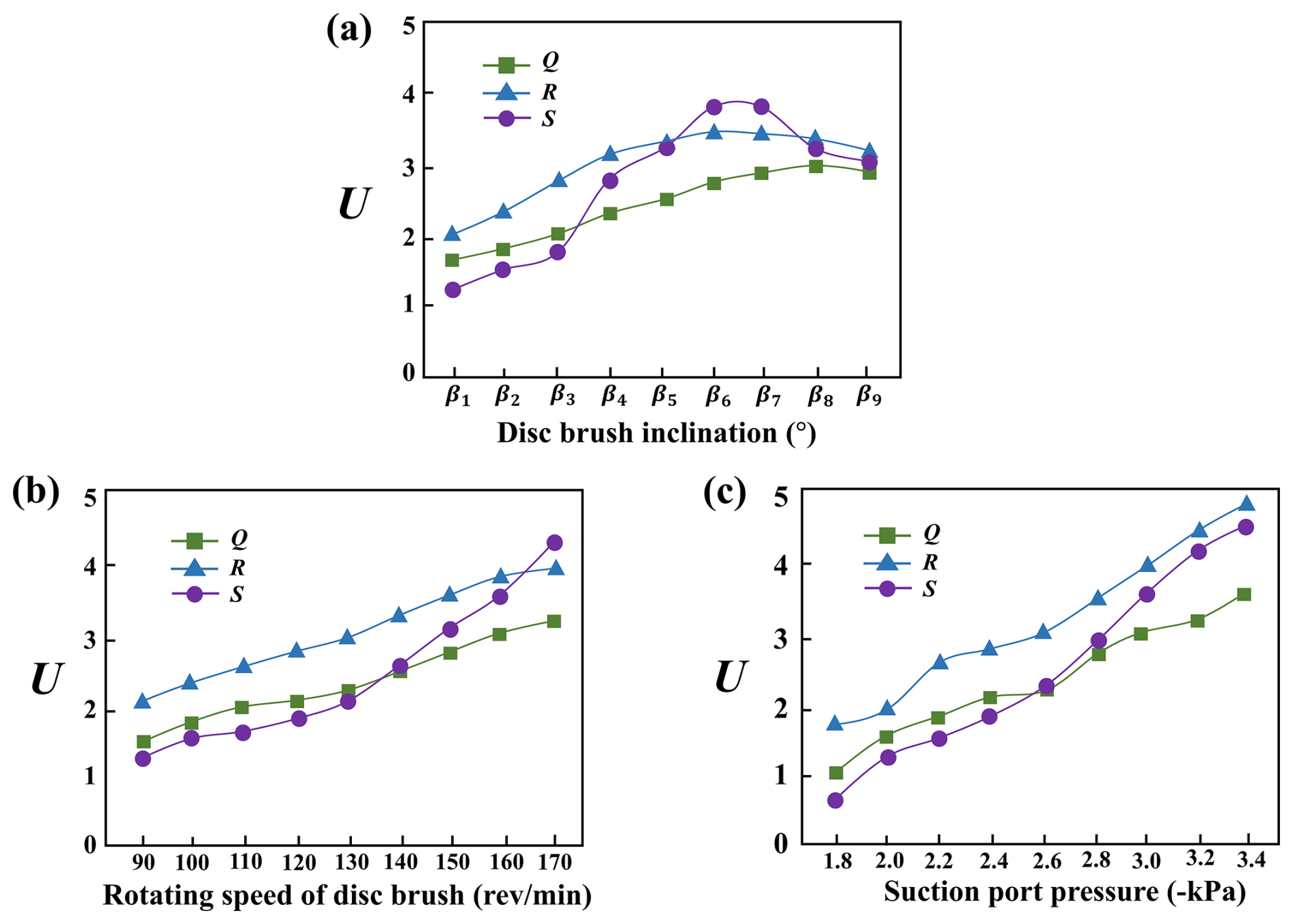
Through an in-depth analysis of key regions, the intrinsic relationship between velocity changes in the coupled region and particle response behavior can be further revealed. As shown in Fig. 13a, as the disk brush angle increases, the position of the velocity extremum point in the flow field shifts significantly, indicating that the disk brush angle has a significant impact on the sweeping trajectory. Excessively large angles may reduce particle recovery efficiency and impair overall cleaning performance. As shown in Fig. 13c, under fixed disk brush angle conditions, appropriately increasing the suction nozzle's negative pressure can enhance the overall airflow velocity within the coupled region, thereby strengthening particle disturbance and adsorption capabilities and improving the suction nozzle's capture efficiency.
3.3 Particle transport mechanism analysis
As the most critical mechanical disturbance component in the cleaning system, the disk brush primarily achieves particle disturbance, aggregation, and transport through rotational motion around its own rotational axis, as shown in Fig. 14. Under the continuous rotational action of the disk brush, particles typically follow a spiral trajectory toward the inner side and ultimately enter the sweeping–suction coupling zone directly in front of the suction nozzle.
In order to further reveal the movement characteristics of particles in the sweeping and suction flow field of sweeper, this study systematically analyzed the dynamic behavior of particles of different sizes under rated operating conditions. Figures 15 and 16 show the movement trajectories and distribution states of particles of different sizes during the sweeping process. The visualization results enable further exploration of the response mechanisms and sweeping paths of particles under the coupled effects of complex airflow and mechanical disturbance.
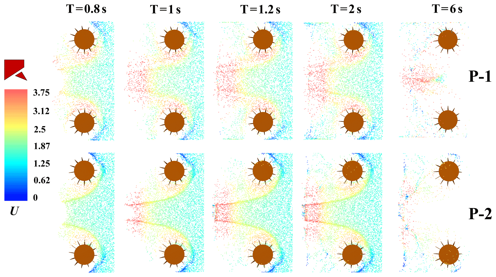
As shown in Fig. 15, particle velocity significantly increases in the region near the suction nozzle, indicating that the tangential airflow generated by the rotating disk brush and the negative pressure from the suction nozzle synergistically exert a strong guiding and accelerating effect on lightweight particles. However, under rated operating conditions, lightweight particles still tend to drift and generate dust. Taking the time point T=2 s as an example, the comparison of the motion states of Particle 1 and Particle 2 at the rear edge of the brush and near the cleaning boundary region shows that a large number of fine particles remain suspended in the air. These results indicate that for particles with lighter mass or smaller particle size, their motion behavior is highly sensitive to airflow disturbances and is easily influenced by non-uniform flow fields, causing them to deviate from the ideal adsorption path.
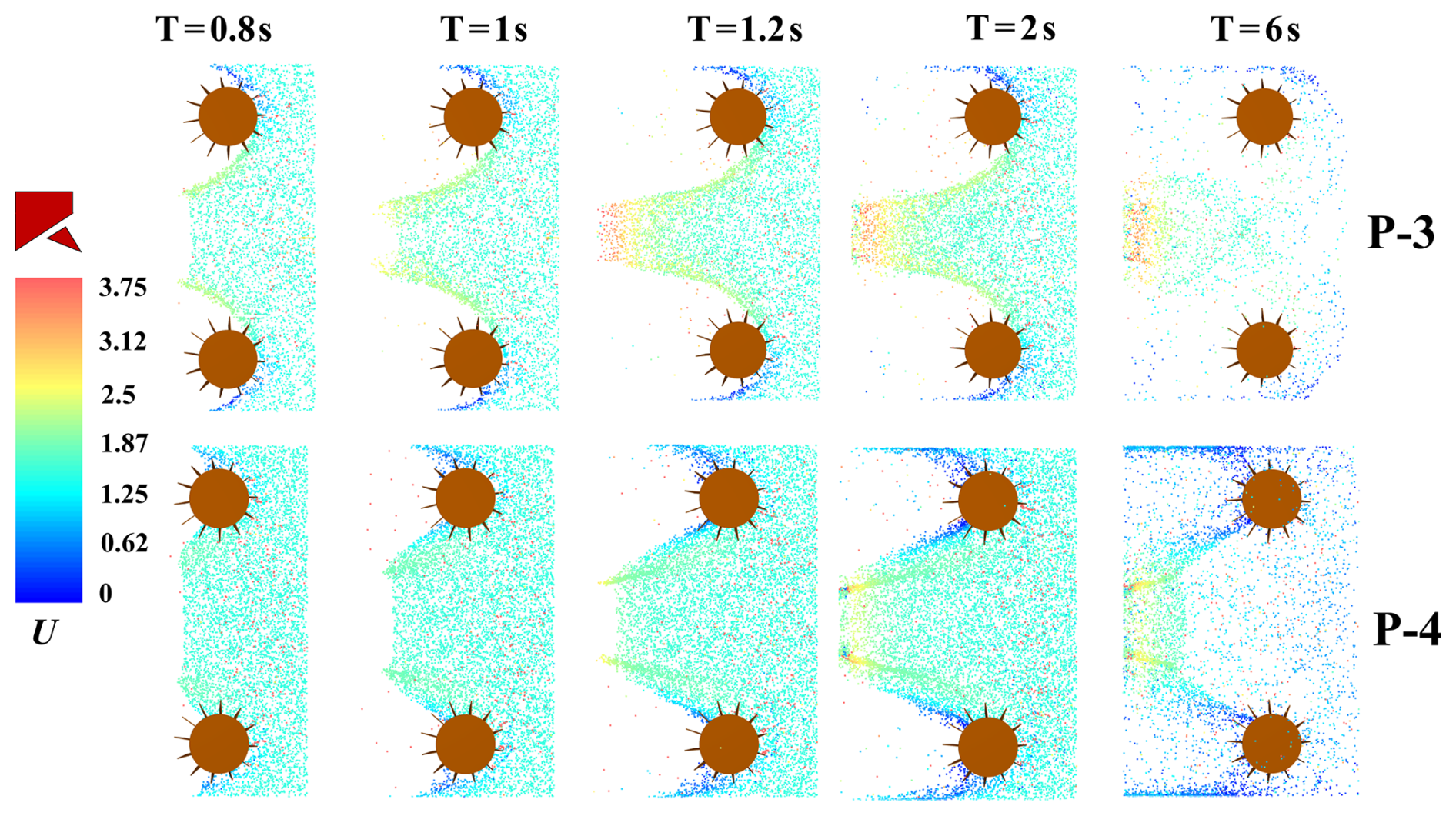
As shown in the computational results of Fig. 16, the movement behavior of large-diameter particles during the sweeping process primarily depends on direct contact with the brush and mechanical propulsion, gradually transporting them from the brush edge to the suction inlet area. Correspondingly, the floating and dusting phenomena of coarse particles in the flow field are significantly reduced, and the sweeping path is more stable. Taking particles with an equivalent diameter of 1 mm as a representative example, their traction by the rotating airflow during sweeping operations is relatively weak. Compared to particles with a diameter of 0.5 mm, the residual quantity of larger particles on the outer side of the brush disk is significantly increased.
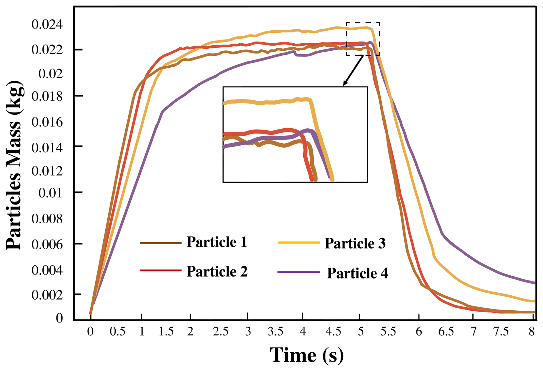
Figure 17 shows the mass change patterns of particles of different sizes over time in the Q-S vertical cross-section under the same operating conditions. The results indicate that within (0–1.5) s, the mass growth rate of smaller particles (e.g., 0.02 mm) in the flow field is significantly faster than that of larger particles. This is primarily because smaller particles are more significantly affected by the turbulent airflow induced by the rotating brush, making them easier to be carried and transported toward the suction nozzle region. However, during the later stages of cleaning, the driving force of the airflow on larger particles significantly weakens, resulting in a greater mass of these particles remaining within the cleaning system.
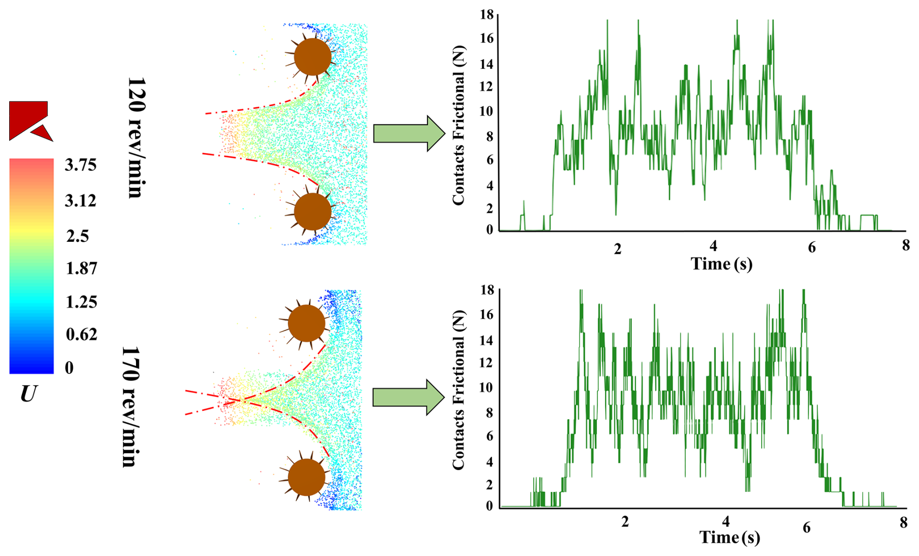
To more intuitively assess the impact of operational parameters on particle cleaning performance, this study compares two typical rotational speed conditions: 120 and 170 rev min−1. As shown in Fig. 18, simulation results indicate that when the rotational speed is increased to 170 rev min−1, particles form distinct crossing trajectory bands in the region in front of the suction nozzle, indicating that high-speed rotation enhances particle disturbance frequency and aggregation trends to some extent. Further analysis of the temporal changes in inter-particle contact friction forces confirms this phenomenon. Under high-speed conditions, frequent contact collisions between particles occur starting from T=1.5 s, with overall contact friction force levels significantly higher than under low-speed conditions. Continuous high-intensity particle contact not only increases system kinetic energy dissipation but may also lead to accelerated wear of brush filament materials and increased vehicle energy consumption. Therefore, while ensuring cleaning efficiency, the setting of operational parameters should fully consider engineering constraints such as system energy consumption and brush filament lifespan to achieve an optimized operational strategy that balances efficiency, stability, and energy conservation.
This study focused on the sweeping and suction system of road sweepers, establishing a numerical simulation model based on a CFD–DEM-coupled approach. It systematically investigated the effects of different operational parameters and particle sizes on sweeping efficiency and particle transport behavior, yielding the following key conclusions.
A reasonable brush inclination angle combined with moderate rotational speed enhances the removal of large particles while maintaining the aggregation and stability of fine particles, thereby significantly improving overall cleaning efficiency. Inclination angles that are too small or too large will weaken particle transport effectiveness, while excessively high rotational speeds may cause fine particles to scatter and increase energy consumption. We recommend controlling the brush rotational speed between 130–160 rev min−1.
Moderate suction effectively improves the recovery of medium-sized particles. However, beyond a critical negative-pressure threshold, cleaning efficiency for fine particles reaches saturation. Further increasing suction yields negligible benefits while increasing energy consumption and system load. Based on the particle size distribution of the road surface, suction port negative pressure should be maintained within the range of −2.6 to −2.8 kPa to achieve an optimal balance between cleaning efficiency and energy consumption.
The sweeping–suction flow field directly determines cleaning performance stability. Fine particles strongly respond to flow disturbances but are prone to dust resuspension; coarse particles rely on brush filament contact for transport. After reasonably matching operational parameters, the airflow disturbance from the disk brush gradually couples with the suction force from the nozzle, forming a stable high-speed adsorption zone. Therefore, operational parameters should be dynamically adjusted based on particle characteristics and working conditions to achieve dual optimization of cleaning efficiency and energy consumption control.
This study still presents certain limitations, including the use of simplified particle geometries, the omission of cohesive and adhesive interactions, and the assumption of idealized boundary conditions. In future research, more realistic particle characteristics – such as irregular shapes, size distributions, and surface roughness – will be incorporated to better represent the physical behavior of debris in real-world sweeping environments. These improvements, combined with targeted experimental validation, are expected to enhance the reliability and applicability of the model, ultimately for understanding particle migration, deposition, and capture mechanisms within sweeping–suction cleaning systems.
Data can be obtained from the corresponding author upon request.
JP, CG, YC, BC, and JL oversaw validation, writing (review and editing), funding acquisition, visualization, formal analysis, and resources. YX oversaw the methodology, software, data curation, and writing (original draft preparation).
The contact author has declared that none of the authors has any competing interests.
Publisher's note: Copernicus Publications remains neutral with regard to jurisdictional claims made in the text, published maps, institutional affiliations, or any other geographical representation in this paper. While Copernicus Publications makes every effort to include appropriate place names, the final responsibility lies with the authors. Views expressed in the text are those of the authors and do not necessarily reflect the views of the publisher.
The authors would like to acknowledge the financial support from the Anhui Province Manufacturing Industry Special Project and The Anhui Airete New Energy Special Purpose Vehicle Co., Ltd. Innovation Project.
This research has been supported by the Anhui Province Manufacturing Industry Special Project (grant no. JB22063) and the Anhui Airete New Energy Special Purpose Vehicle Co., Ltd. Innovation Project (grant no.HX-2025-06-017).
This paper was edited by Liangliang Cheng and reviewed by three anonymous referees.
Bchir, O., Almasoud, S., and Alyahya, L.: A computer vision system for street sweeper robot, Int. J. Adv. Comput. Sci., 13, https://doi.org/10.14569/IJACSA.2022.0131046, 2022.
Beauchemin, S., Levesque, C., and Wiseman, C. L. S.: Quantification and characterization of metals in ultrafine road dust particles, Atmosphere-Basel, 12, 1564, https://doi.org/10.3390/atmos12121564, 2021.
Cho, K. C., Lee, J. S., Shin, H. W., and Park, J. H.: An experimental and numerical investigation of the structural durability of vehicle frames in small electric sweepers, J. Korean Soc. Manuf. Technol. Eng., 20, 116–124, https://doi.org/10.14775/ksmpe.2021.20.01.116, 2021.
D'Andrea, D., Risitano, G., and Alberti, F.: Fuel consumption reduction and efficiency improvement in urban street sweeper using power split with lockup clutch transmission, Appl. Sci., 12, 10160, https://doi.org/10.3390/app121910160, 2022.
Das, S. and Wiseman, C. L. S.: Examining the effectiveness of municipal street sweeping in removing road-deposited particles and metal(loid)s of respiratory health concern, Environ. Int., 187, 108697, https://doi.org/10.1016/j.envint.2024.108697, 2024.
De Almeida, E., Spogis, N., Taranto, O. P., and Ferreira, A.: Theoretical study of pneumatic separation of sugarcane bagasse particles, Biomass Bioenerg., 127, 105256, https://doi.org/10.1016/j.biombioe.2019.105256, 2019.
Desye, B., Geto, A. K., and Berhanu, L.: Occupational respiratory symptoms and associated factors among street sweepers in low- and middle-income countries: A systematic review and meta-analysis, PLoS One, 20, e0320237, https://doi.org/10.1371/journal.pone.0320237, 2025.
Ding, H., Li, J., Wang, H., and Zhang, R.: The flow field simulation and suction structure optimal design of the dual-airway pneumatic fallen jujube fruit pickup device, Turk. J. Agric. For., 48, 26–42, https://doi.org/10.55730/1300-011X.3160, 2024.
El-Emam, M. A., Shi, W., and Zhou, L.: CFD–DEM simulation and optimization of gas-cyclone performance with realistic macroscopic particulate matter, Adv. Powder Technol., 30, 2686–2702, https://doi.org/10.1016/j.apt.2019.08.015, 2019.
Fayzullayevich, J. V., Tan, G., and Alex, F. J.: Improvement of dust particle suction efficiency by controlling the airflow of a regenerative air sweeper, Appl. Sci., 12, 9765, https://doi.org/10.3390/app12199765, 2022a.
Fayzullayevich, J. V., Tan, G., and Alex, F. J.: Numerical study of factors affecting particle suction efficiency of pick-up head of a regenerative air vacuum sweeper, Processes, 10, 1252, https://doi.org/10.3390/pr10071252, 2022b.
Jeong, Y., Kim, W., and Yim, S.: Model predictive control based path tracking and velocity control with rollover prevention function for autonomous electric road sweeper, Energies, 15, 984, https://doi.org/10.3390/en15030984, 2022.
Klöckner, P., Seiwert, B., Weyrauch, S., and Reemtsma, T.: Comprehensive characterization of tire and road wear particles in highway tunnel road dust by use of size and density fractionation, Chemosphere, 279, 130530, https://doi.org/10.1016/j.chemosphere.2021.130530, 2021.
Liu, Y., Ping, P., and Shi, Q.: Research on the cleaning method of unmanned sweeper based on target distribution situation analysis, Appl. Sci., 13, 12544, https://doi.org/10.3390/app132312544, 2023.
Lundberg, J., Gustafsson, M., and Janhall, S.: Temporal variation of road dust load and its size distribution – A comparative study of a porous and a dense pavement, Water Air Soil Pollut., 231, 561, https://doi.org/10.1007/s11270-020-04923-1, 2020.
Lvov, V. and Chitalov, L.: Semi-autogenous wet grinding modeling with CFD–DEM, Minerals, 11, 485, https://doi.org/10.3390/min11050485, 2021.
Ma, H., Ren, W., Yao, F., and Li, J.: Prediction of gas–solid nozzle performance based on CFD and response surface methodology, Powder Technol., 442, 119871, https://doi.org/10.1016/j.powtec.2024.119871, 2024.
Ma, H., Zhang, S., Li, B., and Wang, P.: Local scour around the monopile based on the CFD–DEM method: Experimental and numerical study, Comput. Geotech., 168, 106117, https://doi.org/10.1016/j.compgeo.2024.106117, 2024.
Ma, Y., Zhang, Y., and Song, L.: Ecological and health risk assessment and anthropogenic sources analysis of heavy metals in different types of urban road dust, Process Saf. Environ., 185, 106813, https://doi.org/10.1016/j.psep.2025.106813, 2025.
Pan, J., Ye, J., Ai, H., Wang, J., and Wan, Y.: Parameter optimization of a pure electric sweeper dust port by a backpropagation neural network combined with a whale algorithm, Mech. Sci., 14, 47–60, https://doi.org/10.5194/ms-14-47-2023, 2023.
Parween, R., Clarissa, L. T. L., Naing, M. Y., and Tan, B.: Modeling and analysis of the cleaning system of a reconfigurable tiling robot, IEEE Access., 8, 137770–137782, https://doi.org/10.1109/ACCESS.2020.3009120, 2020.
Rienda, I. C. and Alves, C. A.: Road dust resuspension: A review, Atmos. Res., 261, 105740, https://doi.org/10.1016/j.atmosres.2021.105740, 2021.
Scott, J., Sarabian, T., and Bowers, R.: Assessing the benefits of early and repeated maintenance with regenerative air street sweepers on permeable interlocking concrete pavements, J. Sustain. Water Buil., 8, 06022002, https://doi.org/10.1061/JSWBAY.0000981, 2022.
Sun, Y., Zhu, H., and Liang, Z.: A phase search-enhanced Bi-RRT path planning algorithm for mobile robots, Intell. Robot., 5, 404–418, https://doi.org/10.20517/ir.2025.20, 2025.
Vanegas-Useche, L. V., Abdel-Wahab, M. M., and Parker, G. A.: Effectiveness of oscillatory gutter brushes in removing street sweeping waste, Waste Manag., 43, 28–36, https://doi.org/10.1016/j.wasman.2015.05.014, 2015.
Wagner, S., Funk, C. W., Müller, K., and Becker, T.: The chemical composition and sources of road dust, and of tire and road wear particles – A review, Sci. Total Environ., 926, 171694, https://doi.org/10.1016/j.scitotenv.2024.171694, 2024.
Wang, B., Li, K., and Ye, H.: Distribution characteristics, source analysis of heavy metal(loid)s, and ecological and health risk assessment around shale gas extraction platform in Sichuan, China, Water Air Soil Pollut., 235, 234, https://doi.org/10.1007/s11270-024-07029-0, 2024a.
Wang, H., Huang, F., Fazli, M., and Tan, Z.: CFD–DEM investigation of centrifugal slurry pump with polydisperse particle feeds, Powder Technol., 447, 120204, https://doi.org/10.1016/j.powtec.2024.120204, 2024b.
Wang, H., Wang, C., and Ao, Y.: Fuzzy control algorithm of cleaning parameters of street sweeper based on road garbage volume grading, Sci. Rep., 15, 8405, https://doi.org/10.1038/s41598-025-92771-6, 2025.
Xu, Y., Guo, C., and Chen, Y.: Response surface optimization of cleaning vehicle sweeping suction flow field characteristics and parameter matching, The J. Eng., 2025, e70053, https://doi.org/10.1049/tje2.70053, 2025.
Yang, C., Wu, C., Liu, W., and Zhao, F.: Pneumatic separation and process simulation of waste printed circuit boards pyrolysis residue, Powder Technol., 445, 120075, https://doi.org/10.1016/j.powtec.2024.120075, 2024.
Ye, J., Pan, J., and Ai, H.: Pure electric sweeper performance analysis and test verification of dust extraction port, Appl. Sci., 12, 5188, https://doi.org/10.3390/app12105188, 2022a.
Ye, J., Pan, J., and Ai, H.: Relationship between flow field characteristics and dust collection efficiency of sweeper suction port, The J. Eng., 2022, 389–400, https://doi.org/10.1049/tje2.12122, 2022b.
Yong, T., Zhengtao, W., Jian, S., and Zhang, X.: Design and optimization of a vacuum system for a large storage tank cleaning robot, Inmateh Agric. Eng., 73, https://doi.org/10.35633/inmateh-73-57, 2024.
Zhang, L., Cai, K., and Sun, Z.: Motion planning for robotics: A review for sampling-based planners, Biomim. Intell. Robot., 100207, https://doi.org/10.1016/j.birob.2024.100207, 2024a.
Zhang, Q., Zhong, C., Fang, Z., and Xu, Y.: Impact of fibers on pumping flow: an analysis by CFD–DEM simulations and experiments, Acta Mech., 236, 767–787, https://doi.org/10.1007/s00707-024-04176-7, 2025.
Zhang, Y., Li, J. N., and Zhang, L. H.: Brominated flame retardants in road dust and green belt soil from Harbin China: Contamination characteristics sources and health risks, Environ. Chem. Ecotoxicol., 6, 229–235, https://doi.org/10.1016/j.enceco.2024.05.009, 2024b.
Zhou, J., Xu, Y., Guo, X., and Liu, P.: Numerical simulations on the flow regime characteristics of horizontal pneumatic conveying using CFD–DEM, Powder Technol., 438, 119641, https://doi.org/10.1016/j.powtec.2024.119641, 2024.
Zhou, W., Dai, G., and Jiang, Y.: Numerical analysis on the airflow organization of a blowing suction dust collector, Sci. Rep., 15, 10244, https://doi.org/10.1038/s41598-025-94767-8, 2025.