the Creative Commons Attribution 4.0 License.
the Creative Commons Attribution 4.0 License.
 | 26 Nov 2025
Wind-induced vibration control for tower cranes based on a rear-mounted, mass-sharing bi-directional tuned mass damper
Lingyun Yang
Xiafeng Hu
Yong Song
Zihan Yu
Yiran Sun
Hongyu Zhou
Wenming Cheng
This study introduces a novel bi-directional tuned mass damper (Bi-TMD) for tower cranes that is rear mounted and shares mass with the counterweight, overcoming the spatial and structural limitations of conventional designs. Unlike traditional top-mounted or mid-tower dampers, the proposed Bi-TMD is integrated into the counterweight, where movable masses on spring–damper units replace a portion of the concrete ballast. This design preserves the crane's lifting capacity while enabling bi-directional control of both sway and torsional vibrations. Finite-element simulations under Kaimal-spectrum fluctuating wind loads (ANSYS, 21 m s−1) show that the Bi-TMD, with a 5 % modal mass ratio, reduces peak tower-top acceleration and displacement by approximately 49 % and 24 %, respectively. Parametric studies yield three key findings: (1) the counterweight-mounted TMD provides effective vibration suppression, particularly for along-wind sway, without compromising structural integrity; (2) an optimal modal mass ratio of 3 %–4 % maximizes control efficiency and avoids local resonance, especially under cross-wind conditions; and (3) the rear-mounted Bi-TMD achieves 75 %–91 % of the performance of a mid-mounted TMD while avoiding spatial interference at the tower head. These results demonstrate that the Bi-TMD is as a practical and scalable solution for retrofitting existing cranes and for use in space-constrained environments.
- Article
(2082 KB) - Full-text XML
-
Supplement
(589 KB) - BibTeX
- EndNote


Tower cranes are indispensable in modern construction, providing the heavy-lifting capacity required for demanding projects, such as skyscrapers, long-span bridges, offshore wind turbines, and port logistics. As extreme-weather events become more frequent and intense, these cranes face unprecedented challenges to their wind-resistance capabilities. The Big Blue crane collapsed at Miller Park in 1999 during a lift in high winds (avg 11.62 m s−1, gusts mid-30s) (Ross et al., 2007). The catastrophic overturn, which killed three workers, was primarily caused by excessive wind-induced side loads on the crane and the large, suspended roof panel. While most existing studies address static wind loads, the dynamic impact of fluctuating winds remains relatively underexplored. Recent work shows that wind-induced vibrations in turbulent conditions can severely undermine structural stability and even cause damage (Tan et al., 2024; Qin et al., 2021). A detailed investigation of dynamic wind responses and the development of effective vibration control strategies for structures that have repeatedly failed in service (Huang et al., 2017; Liang et al., 2023) are essential for ensuring operational safety and structural integrity.
Among vibration control devices, the tuned mass damper (TMD) is one of the most widely applied and thoroughly studied solutions in civil and mechanical engineering. Extensive research on various structural systems and loading scenarios – including the construction phases of long-span bridges (Kim et al., 2012; Wang et al., 2024) or even the absorbance of the vibrations of high-speed trains (Sun et al., 2022) – has consistently confirmed the TMD's effectiveness in suppressing undesirable modal vibrations. By absorbing and dissipating vibrational energy, TMDs significantly reduce key response metrics such as peak displacement and stress, thereby enhancing structural safety, especially under the wind loading conditions close to the resonant frequency of tower cranes (Li et al., 2021). Zhang et al. (2025) conducted on-site stress measurements and orthogonal experiments on a flat-arm tower crane, identifying the tower body root as the critical stress area and determining its natural frequencies. It was determined that lifting position and rope length are the primary factors influencing structural stress, providing a basis for safety assessment and optimized design.
Tower cranes are tall boom structures whose wind-induced vibrations directly affect construction safety and equipment lifespan. Active-control technologies can suppress these vibrations (Wang et al., 2021; O'Connor and Habibi, 2013). Sun et al. (2025), for example, applied a mixed strategy with encouraging results – but active systems are costly to install and maintain. Liang and Yang (2025) improved the structure of tower cranes. The core of this tower crane lies in the design and implementation of its swinging trolley structure, which has positioning and attitude adjustment functions and can achieve precise lifting of prefabricated components. However, active-control systems are characterized by relatively high costs and maintenance complexities. Passive approaches adapted from building-scale TMDs also have shortcomings. (1) Distributed TMDs placed at several heights can tame multiple modes, yet the extra dampers raise self-weight and alter mass distribution, increasing dynamic loads on section bolts and accelerating fatigue (Sun, 2024; Wang and Zhang, 2025; Le et al., 2024; Wang et al., 2025). This imposes additional dynamic loads on standard-section connection bolts, risking fatigue damage. (2) Top-mounted TMDs, inspired by wind turbine practice (Bi, 2018; Ding et al., 2023; Kong et al., 2025), target individual modes but must fit near the slewing mechanism, where space is limited; their added mass weakens the tower head and conflicts with code limits on working radius and rated capacity.
To address these issues, we propose a rear-mounted TMD integrated into the counterweight. Following a mass-equivalence principle, 6 %–39 % of the conventional concrete ballast is replaced by movable masses connected to springs and dampers. The design offers three key benefits. (1) It preserves the original static load path, minimizing structural disturbance. (2) Electromagnetic or mechanical locks enable mode switching – locked for normal counterweight duty and automatically released as a TMD when wind speed exceeds a threshold. (3) Although not at the point of maximum displacement, the counterweight's long lever arm about the slewing axis maximizes inertia per unit TMD mass, delivering mitigation efficiency comparable to top-mounted systems.
The paper is organized as follows. The model and configuration of Bi-TMD are presented in Sect. 2. The wind load and modal analyses are in Sect. 3. In Sect. 4, the responses with Bi-TMD are comprehensively discussed, justifying our findings. The concluding remarks are summarized in Sect. 5.
2.1 TMD parameter design
Figure 1 illustrates the interaction model between a TMD and the host structure. Under fluctuating wind excitation, for example, the system's equations of motion along the x direction (similar along the z direction) are
where m1 represents the host structural mass; m2 represents the damper mass; C1x represents the structural damping coefficient; C2x represents the damper damping coefficient; K1x represents the structural stiffness; K2x represents the damper stiffness; x1 and x2 represent the displacements of the structure and the damper, respectively; and F(t) represents the external excitation caused by fluctuating winds.
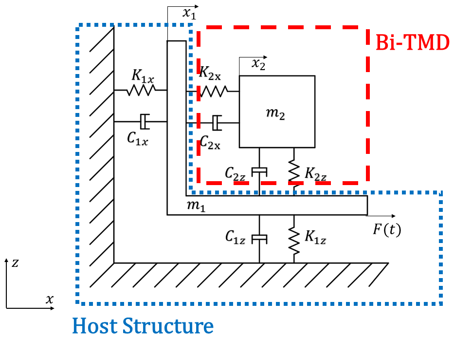
Figure 1 also presents the theoretical Bi-TMD model. We determine the x-direction stiffness KTMD1 and damping CTMD1 and the z-direction stiffness KTMD2 and damping CTMD2 independently. To analyze the x-direction response, a modal study identifies the dominant nth mode. Following Sadek's optimal TMD design method (Sadek et al., 1997), the TMD parameters are then derived as follows.
In practice, a TMD usually weighs 1 %–7 % of the crane, but more mass, while widening the control bandwidth (Tong and Zhang, 2007), raises structural loads, which will increase the structure stress. We here define the modal mass ratio as
where μ is the TMD modal mass ratio, is the modal mass of the tower crane for the nth mode, and mTMD is the TMD mass.
For the dominant nth mode, Sadek's formulas (Sadek et al., 1997) give the optimal tuning
where is the damping ratio of the tower crane for the nth mode.
The optimal damping ratio εTMD is given by
The optimal TMD frequency is derived as
where is the natural frequency of the tower crane for the nth mode.
The stiffness K2x and damping C2x are computed by
This completes the calculation of the x-direction stiffness K2x and damping C2x for the Bi-TMD. The z-direction parameters K2z and C2z are obtained identically.
Theoretical analysis based on the optimization theory of vibration control systems indicates that, within the framework of the classic tuned mass damper (TMD) design for tower cranes, the damping ratio parameter exerts a relatively weaker influence on the vibration control response compared to the mass parameter. This finding aligns with previous research (Nagarajaiah, 2009), which has consistently reported the dominance of the mass parameter in determining the overall performance of TMDs. Specifically, studies (Zhang et al., 2008) have demonstrated that the vibration suppression bandwidth of a TMD exhibits a monotonically increasing relationship with the mass ratio. A higher mass ratio not only effectively extends the controlled frequency range but also significantly enhances the vibration suppression performance, enabling the TMD to more efficiently mitigate wind-induced vibrations across a broader spectrum of frequencies.
However, when tower cranes are involved, stringent structural load limitations must be considered. The addition of excessive mass to the tower crane structure through the TMD can compromise the overall structural integrity and operational safety, as well as increase material and installation costs. Therefore, the added mass of the TMD must be strictly controlled within a reasonable threshold to ensure that it does not exceed the load-bearing capacity of the tower crane while still achieving effective vibration control.
To this end, we systematically simulate the TMD across a suite of modal mass ratios from 1 % to 5 %. This parametric study is designed to reconcile vibration suppression demands with structural loading concerns. The resulting data provide comprehensive insights into TMD performance under mass configurations that are both structurally admissible and operationally meaningful for tower cranes.
2.2 TMD mounting positions
The placement of tuned mass dampers (TMDs) is a key factor in how effectively they reduce wind-induced vibrations in tower cranes. To evaluate different mounting strategies, this study compares two TMD configurations as seen in Fig. 2.
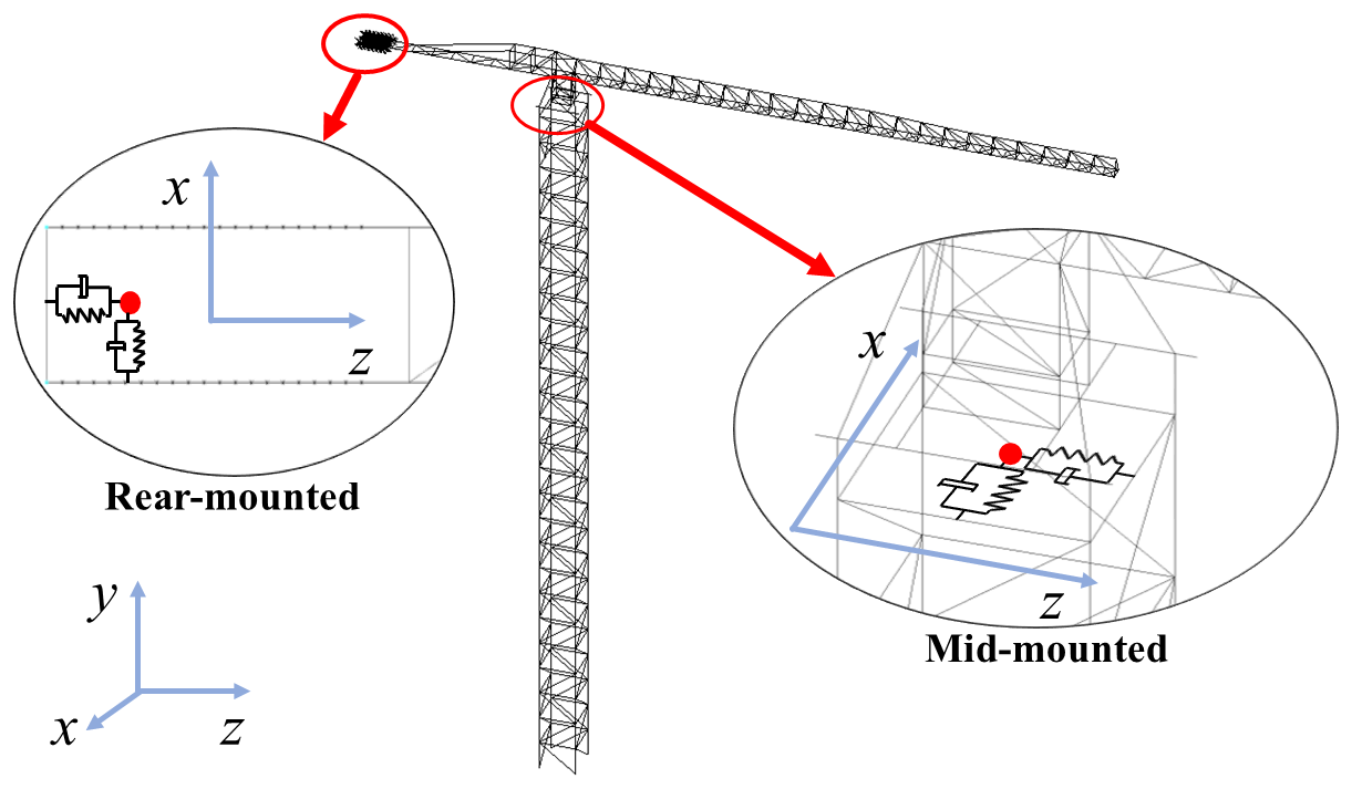
2.2.1 Mid-mounted TMD – baseline group
The TMD is installed near the operator's cab at the tower top – the zone of maximum vibration under wind loading. Dynamic theory indicates that locating the TMD in such high-response zones provides greater relative displacement, enhancing resonant coupling with the main structure and maximizing energy dissipation. Prior research (de Sebastian-Sanz et al., 2009) shows that the vibration control performance of a mid-mounted TMD improves as the mass ratio increases. Accordingly, we use modal mass ratios of 1 %, 3 %, and 5 % as benchmarks to balance computational cost and accuracy.
2.2.2 Rear-mounted TMD – experimental group
The experimental design integrates the TMD within the rear counterweight, a location distant from the primary vibrational anti-node. This configuration's damping behavior is less documented. Our study addresses this by conducting a parametric study across five mass ratios (1 %–5 %). This systematic variation yields a detailed performance dataset, enabling a direct comparison with the baseline and helping to elucidate the working principles of TMDs when decoupled from the point of peak response.
3.1 Tower crane model
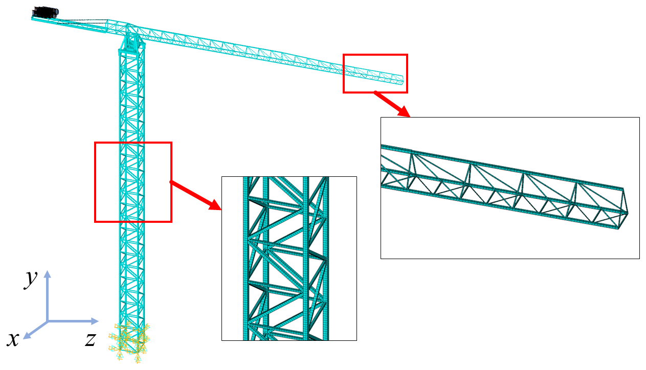
Finite-element analyses were conducted in ANSYS APDL 2021 R1 to evaluate the tower crane's wind-induced dynamic response. Because the crane is a slender steel structure assembled from standardized sections, the main framework – the tower mast, slewing platform, and jib arms – was modeled with BEAM188 elements, each providing 6 degrees of freedom per node. Cross-sectional properties (area, moments of inertia, etc.) were assigned according to the manufacturer's data for each segment to balance computational efficiency and accuracy. Components that contribute little to the global vibration modes – such as the operator's cab, guardrails, and fixed counterweights – were represented as lumped masses using MASS21 elements rigidly attached to the corresponding beam nodes. This beam-and-mass idealization greatly accelerates transient wind load simulations while preserving the key modal characteristics observed in a full solid model. The finite-element assembly, showing element connectivity and the fixed-base boundary condition, is presented in Fig. 3. The direction parallel to the jib (along wind) is defined as the x direction, and the direction perpendicular to the jib (cross-wind) is defined as the z direction.
3.2 Wind load simulation
A 600 s fluctuating-wind record was generated with the Kaimal spectrum and harmonic superposition technique. Wind loading is decomposed into steady and turbulent components that have distinctly different timescales. The steady (mean) wind, whose characteristic period exceeds roughly 10 min, is treated as a static load in design practice (Cheng et al., 2014):
where v(z,t) is the total wind speed at height z, represents mean wind speed, and u(z,t) represents fluctuating wind speed.
The height-dependent mean profile is described with Davenport's exponential law (Zhang, 1990):
where is the average speed at reference height z, is the average speed at reference height zr, and α is the wind profile exponent.
Fluctuating wind components exhibit characteristic periods of 10 s (0.1 Hz), placing their energy squarely within the frequency band that can excite the crane's natural modes. When such frequency alignment occurs, resonant wind-induced vibrations may develop, making full dynamic analysis essential (Davenport, 1983). In this study, the mean profile is modeled with the exponential law, consistent with boundary-layer theory, while the turbulent component is synthesized from the Kaimal power spectral density, a spectrum that has been widely validated for neutral-stability atmospheric boundary layers (Kaimal et al., 1972). Treating the mean flow and turbulence separately in this way captures the vertical heterogeneity of wind loads across the crane's height and provides realistic input for dynamic response simulations.
The Davenport power spectral density (PSD) (Davenport, 1965) is
where Su(n) is the longitudinal turbulence PSD, K is the surface drag coefficient, n is the frequency, n0 is the dimensionless frequency, U(10) is the mean wind speed at the 10 m reference height, and U(z) is the mean speed at height z.
The Kaimal power spectral density (PSD) (Kaimal et al., 1972) is
where Su(n) is the longitudinal turbulence PSD, u0 is the friction velocity, and U(z) is the mean speed at height z.
Building on Rice's stochastic process framework (Rice, 1944) and Shinozuka's numerical implementation (Shinozuka, 1971), the zero-mean fluctuating wind at m spatial points is synthesized as
where φkl is a random phase uniformly distributed in [0,2π]; , with fz being the cut-off frequency; N is the data length; N≥2M, M is the number of discrete frequency points; ; and ωkl is the double-indexed angular frequency, which is defined as
Hjk(ωkl) is obtained from the Cholesky decomposition matrix of the m×m cross-spectral density matrix S(ωl):
where θjk is the phase angle of Hjk(ωkl):
Writing Eq. (13) in complex exponential form facilitates a fast Fourier transform (FFT) solution:
Let , then Eq. (18) can be written as
where , and Gjk(qΔt) is defined as
Equation (18) can be computed using an FFT. After computation, substituting the results into Eq. (19) yields the fluctuating wind field at m points.
Figure 4 shows the 600 s wind speed time history at the tower top for a 21 m s−1 (Beaufort scale 9) reference wind.
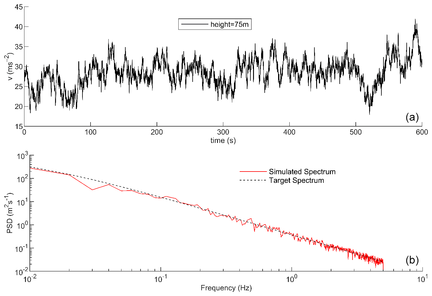
Figure 4Fluctuating-wind simulation: (a) wind speed time history and (b) comparison of simulated spectrum and target spectrum.
Wind loading on tall, slender structures such as tower cranes varies markedly with height because of the non-uniform nature of the atmospheric boundary layer. To keep the crane–TMD dynamic analysis both efficient and sufficiently accurate, we adopted a simplified yet representative wind load model. Within each standardized structural segment (treated as a single unit), the mean wind speed was assumed uniform and applied at the segment's centroid. Fluctuating wind forces were then calculated using the aerodynamic shape coefficients given in the design code (Standardization Administration of the People's Republic of China, 2017). These forces were converted to equivalent static nodal loads and assigned to eight key nodes in every standard segment. For the boom, which has a more complex geometry, the nodal density was increased to 12–15 nodes per segment to capture the finer distribution of wind pressure. The selected wind speeds of 13.8 m s−1 (Beaufort scale 6) and 21.0 m s−1 (Beaufort scale 9) are based on the Standardization Administration of the People's Republic of China (GB/T 13752-2017: design rules for tower cranes). These values represent the maximum allowable wind speed during standard operation and a severe storm condition during non-operation, respectively, allowing for a comprehensive evaluation of the Bi-TMD's performance across critical design scenarios. We consider the following wind speed design cases: (1) working state with max 13.8 m s−1 (Beaufort force 6), including simulations for longitudinal and transverse directions, and (2) non-working state with max 21.0 m s−1 (Beaufort force 9), with the slewing mechanism unlocked and for the longitudinal direction only.
3.3 Modal analysis results
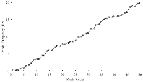
In total, 50 eigenmodes – spanning roughly 0–20 Hz – were extracted from the finite-element model (Fig. 5). The first six modes fall below 1.4 Hz and dominate the structural response (Table 1 and Fig. 6).
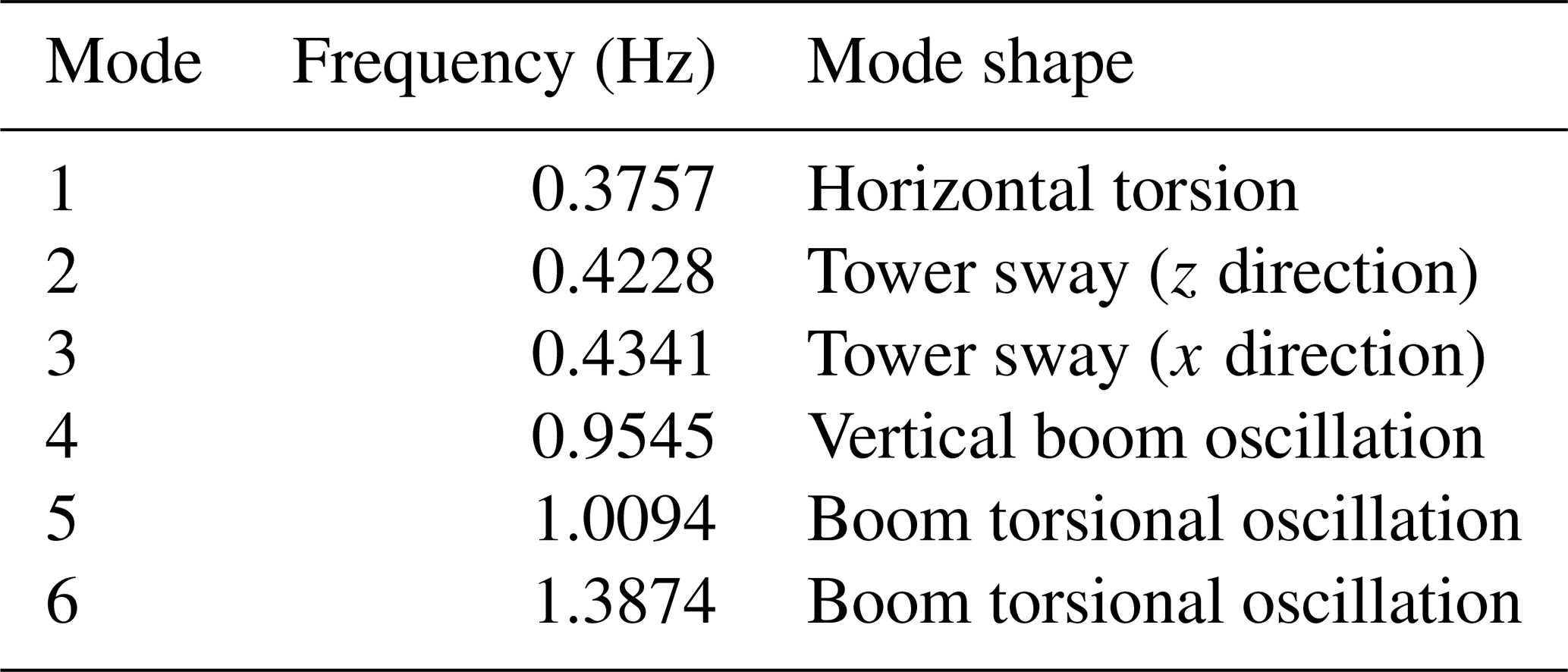
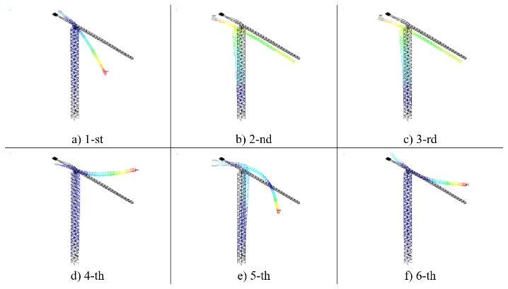
Mode 1 (0.376 Hz) is the global horizontal torsion of the tower-boom assembly. Mode 2 (0.423 Hz) is the fundamental tower sway in the windward z direction. Mode 3 (0.434 Hz) is tower sway in the transverse x direction. Mode 4 (0.955 Hz) is characterized by vertical boom oscillation, primarily driven by the jib's self-weight. Modes 5–6 (≈1.01 and 1.39 Hz) are boom torsional oscillations about the jib axis.
Among these, the two sway modes carry the overwhelming share of dynamic participation: together they account for 93.34 % of the total effective mass, making them the primary targets for vibration control. The remaining low-frequency modes (torsion and boom bending/torsion) contribute only a small fraction of the effective mass and therefore have a secondary influence on wind-induced responses.
Table 2 lists the conditions for analysis. Wind-induced responses were assessed under two scenarios: (1) a working state of 13.8 m s−1 (Beaufort force 6) in the transverse (0°, z) and longitudinal (90°, x) directions and (2) a non-working state of 21.0 m s−1 (Beaufort force 9) in the longitudinal direction only.
Table 2Brief description of working conditions.

Vibration control results obtained with the Bi-TMD (5 % modal mass ratio) were compared with the uncontrolled case to produce the control curves shown in Fig. 7 for the 21 m s−1 along-wind load.
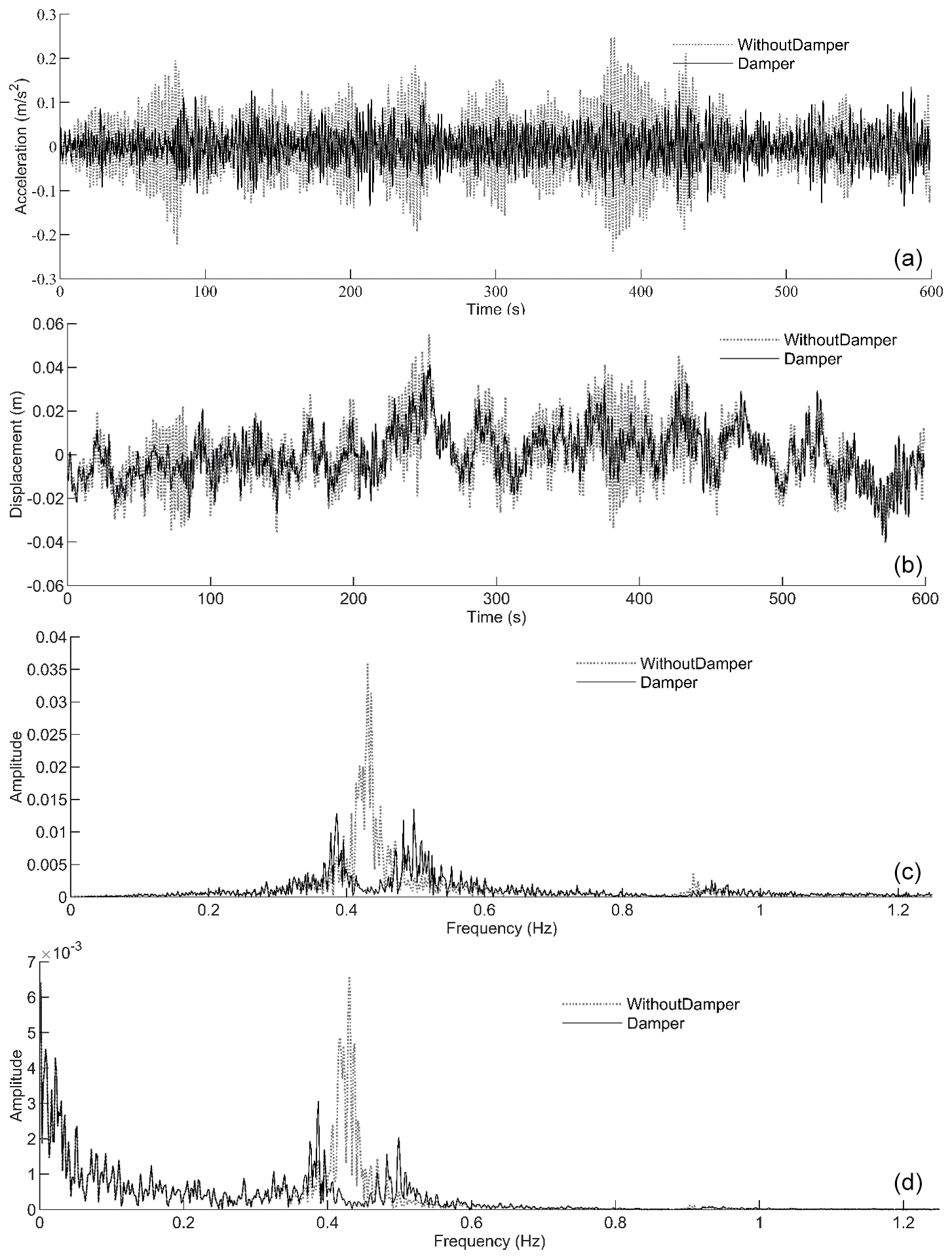
Figure 7Suppression effect: (a) time-domain acceleration suppression response, (b) time-domain displacement suppression response, (c) frequency-domain acceleration suppression response, and (d) frequency-domain displacement suppression response.
The TMD clearly mitigates the response. Peak acceleration falls from 0.24 to 0.0925 m s2 – a reduction of 61.5 %. Peak displacement drops from 0.054 to 0.040 m, a decrease of 25.9 %. Frequency-domain analysis corroborates these findings, revealing a marked reduction in spectral amplitudes.
To quantify control performance, the effectiveness index R is defined as
where RMS0 represents the root mean square (RMS) of wind-induced vibration responses under uncontrolled conditions, while RMS1 represents the RMS of wind-induced vibration responses with TMD installed.
For a comprehensive assessment across the crane, responses were recorded at four measurement points, whose locations are listed in Table 3. The four measurement points were strategically selected to capture the dynamic responses at structurally critical and representative locations of the tower crane: Point 1 (operator's cabin) is at the tower top, where acceleration is most critical for operator comfort and safety; Point 2 is at the mid-tower to monitor global bending behavior; Point 3 is at the counterweight to directly assess the local performance of the rear-mounted Bi-TMD; and Point 4 is at the jib tip, which experiences the largest displacements and is highly sensitive to torsional vibrations, making it a key indicator of overall structural safety.
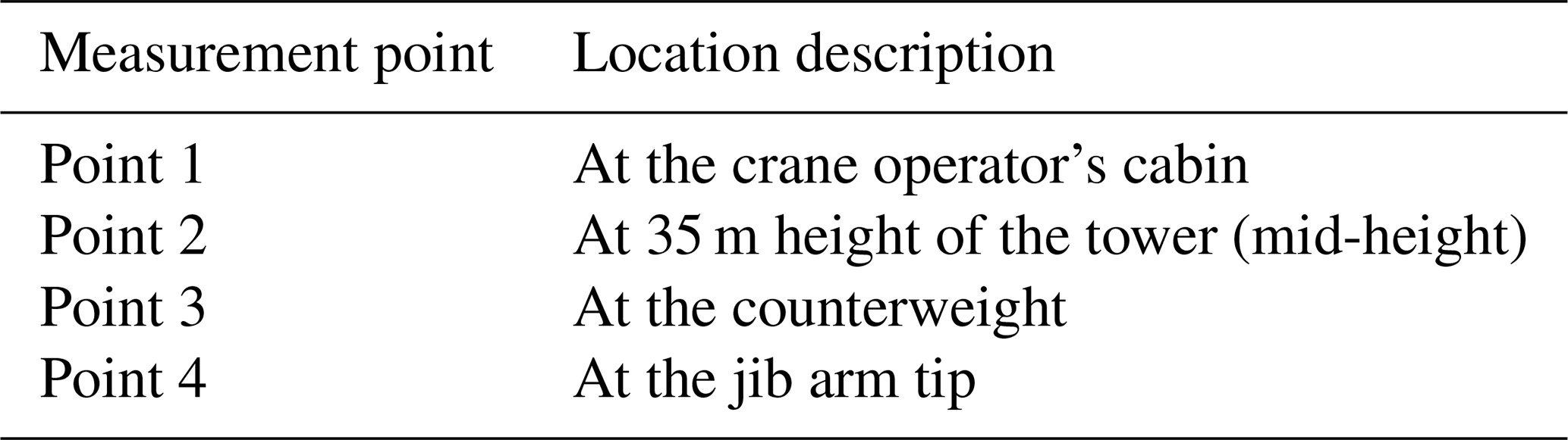
Figure 8 summarizes the performance of the rear-mounted TMD: panels a–c show the reductions in acceleration, whereas panels d–f display the corresponding displacement control. Figure 9 presents the results for the mid-mounted TMD, with panels a–c illustrating acceleration mitigation and panels d–f highlighting displacement reduction.
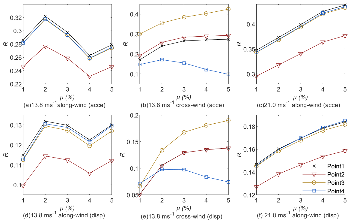
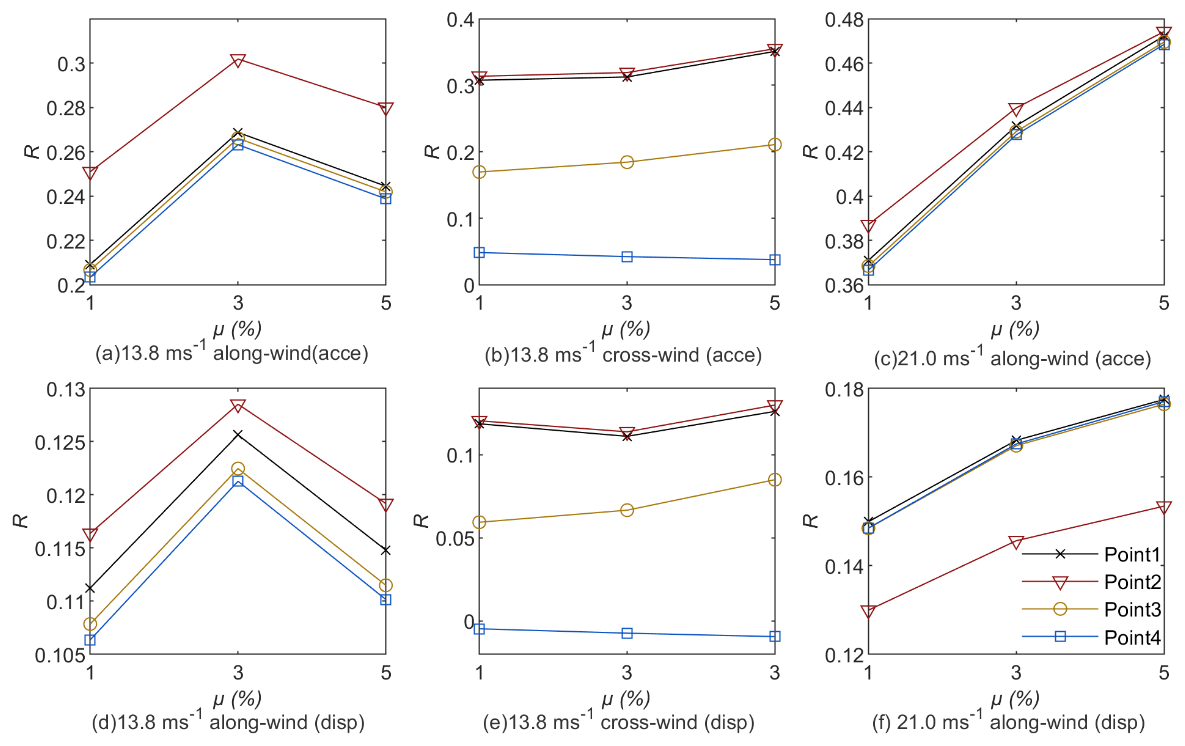
Tables 4 and 5 present the detailed data on the reductions in acceleration and displacement under different installation modes.
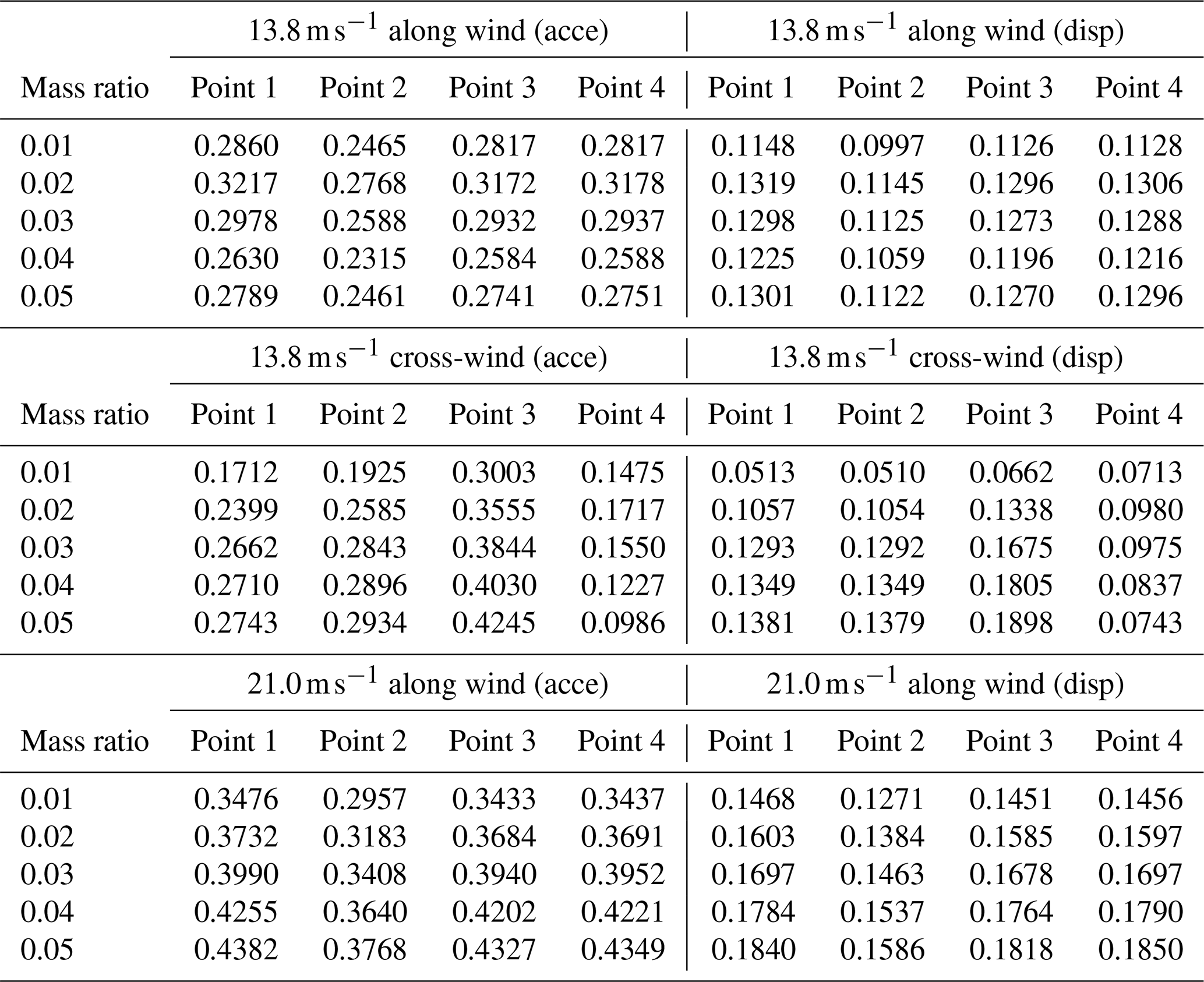

Synthesizing the results of Bi-TMD and conventional TMD yields several observations. First, both systems exhibit a clear “sweet-spot” mass ratio: about 3 % for the rear mount and about 2 %–3 % for the middle mount. Below those thresholds, the dampers lack sufficient inertia, whereas above them, additional mass produces little extra benefit and can locally detune the system. Second, the mid-tower TMD excels in pure along-wind sway control but offers limited help against cross-wind-induced torsion, while the rear Bi-TMD, thanks to its long moment arm, provides more balanced – albeit slightly lower – gains across both directions. Third, under extreme winds, the relative jump in effectiveness is larger for the rear-mounted scheme, confirming that its mass-sharing concept becomes more potent as aerodynamic loads escalate. Altogether, the figures demonstrate that a carefully tuned rear-mounted Bi-TMD can routinely deliver between 75 % and 91 % of the mid-mounted device's performance, yet it avoids the spatial and maintenance complications inherent to tower-head installations, making it a compelling choice for retrofits and height-constrained cranes.
This study clarifies how TMD location, mass ratio, and wind direction interact in tower cranes, and it establishes a three-tier “location–mass-ratio–wind-direction” design framework, with the main findings as follows:
- 1.
Installation location governs effectiveness. Mounting the TMD inside the counterweight markedly attenuates vibrations in the counterweight region. Under Beaufort-6 along-wind loading, the accelerationreduction ratio at that location reached 0.281–0.318, which is 23.7 %–30.5 % higher than the reduction achieved with tower-center mounting. This improvement arises from the inertial synergy between the TMD and the counterweight, which effectively suppresses coupled vibrations of the tower and counterweight. By contrast, placing the TMD at the tower center is more effective at limiting tower-top displacements because it directly targets the primary bending modes. For sites dominated by along winds, designers should prioritize the counterweight-mounted scheme with a mass ratio of 0.03–0.04 to maximize vibration suppression at the counterweight.
- 2.
The influence of the TMD mass ratio is nonlinear. Increasing the mass ratio from 0.01 to 0.05 generally enhances vibration mitigation but exhibits diminishing marginal returns. For example, with the counterweight-mounted scheme under Beaufort-6 cross-wind loading (Fig. 8b), the accelerationreduction ratio at Point 1 rises from 0.17 to 0.24 (a 41.1 % gain), whereas the increment from 0.03 to 0.05 yields only a 3.8 % gain. A critical-mass-ratio effect was also observed. When the TMD is mounted at the tower center under cross-wind loading (Fig. 9e), a negative reduction ratio (−0.0046 to −0.0093) emerges at the jib tip (Point 4), indicating that an excessively large TMD mass can trigger local resonance. The observed negative control effectiveness (i.e., response amplification) at the jib tip for the mid-mounted TMD under cross-wind excitation, particularly at higher mass ratios, can be attributed to a localized resonance effect. The substantial added mass of the TMD itself alters the global dynamics of the crane structure. This mass modification can shift the natural frequencies of the system, potentially causing the vortex-shedding frequency in the cross-wind direction to couple more strongly with a higher-order, localized bending or torsional mode of the long, flexible jib. When this frequency alignment occurs, the TMD structure system can enter a detrimental coupled resonant state, amplifying the response at the jib tip rather than suppressing it. This underscores the importance of avoiding over-tuning and carefully selecting the TMD mass to prevent such adverse interactions in slender, complex structures. This resonance is caused by coupling between the vortex-shedding excitation frequency in cross-winds and the higher-order modes of the combined TMD–jib system and must therefore be avoided in design.
- 3.
Wind load characteristics play a critical role. Vibration control is significantly more challenging under cross-wind loads than under along-wind loads. For the counterweight-mounted scheme, the accelerationreduction ratio at the jib tip under cross-winds (Fig. 8b: 0.147–0.172) is 45.9 %–51.2 % lower than under along winds (Fig. 8a: 0.282–0.318). Moreover, the cross-wind data exhibit larger scatter (standard deviation 0.012 versus 0.002), reflecting greater sensitivity to turbulence intensity. TMD effectiveness improves at higher wind speeds. Under Beaufort-9 along winds (Fig. 8f), the displacementreduction ratio at Point 1 reaches 0.178–0.184, which is 41.5 %–54.8 % better than under Beaufort-6 conditions (Fig. 8a: 0.115–0.130). These results confirm the TMD's potential for broadband control in extreme winds. Under very high wind speeds (Beaufort 9 or higher), increasing the mass ratio to 0.04 can enhance broadband control capacity.
- 4.
The jib tip is highly sensitive and poses a design risk. The jib tip (Point 4) consistently shows low or even negative control effectiveness under cross-wind excitation (e.g., Fig. 8e: 0.071–0.098). This vulnerability is mainly due to the long cantilever's sensitivity to phase-lag effects introduced by the TMD. For sites exposed to strong or highly variable cross-winds, designers should favor the tower-center scheme with a mass ratio not exceeding 0.03, thereby preserving tower stability and avoiding negative control at the jib tip.
Using finite-element models, this study assessed a rear-mounted, mass-sharing bi-directional TMD (Bi-TMD) for tower crane wind-vibration control. The primary findings demonstrate that the rear-mounted Bi-TMD offers a practical and effective solution, achieving 75 %–91 % of the control performance of a mid-mounted TMD. Although a counterweight-mounted TMD is inherently less efficient due to its distance from the point of maximum displacement, systematic tuning enables competitive performance. Key design considerations include an optimal modal mass ratio of 3 %–4 % for the rear-mounted configuration, the heightened challenge of cross-wind control, and the sensitivity of the jib tip. Consequently, the rear-mounted layout presents a compelling choice for retrofitting existing cranes and for deployment in space-constrained environments, as it avoids the spatial and maintenance complications associated with tower-head installations while preserving lifting capacity through its mass-sharing principle.
In contrast to studies that simplify wind loading as a static force, the investigation by Chen et al. (2020) on a tower crane underscores the critical importance of dynamic and multi-directional wind effects for safety evaluation. Their integrated CFD-FEM analysis revealed a pivotal finding: while the maximum along-wind load occurred at a deflected 30–60° angle, the most unfavorable structural responses in displacement and stress were unexpectedly observed at the 0° wind direction under fluctuating winds. Furthermore, they demonstrated that across-wind loads, though often neglected, were significant, with a mean ratio of 8.56 %, to the along-wind loads, challenging the conventional design focus solely on along-wind forces. Crucially, their time-domain analysis exposed that the structure, while compliant with static design rules, experienced bending stresses at key junctions (e.g., jib-slewing platform) that exceeded allowable limits and experienced excitation of its fundamental mode. These results compellingly argue that traditional static analysis can be non-conservative, potentially leading to unsafe designs. Consequently, Chen et al. (2020) advocate for the mandatory inclusion of fluctuating wind loads and across-wind loads in safety assessments, suggesting structural reinforcement at critical joints and considering vibration control devices for enhanced reliability, thereby setting a benchmark for a more rigorous and realistic evaluation framework.
The future research plan is as follows:
-
The main limitation of this study is its neglect of continuously varying wind-yaw angles. Follow-up work should include dynamic analyses with continuously varying wind-yaw angles to better simulate realistic turbulent inflow conditions and assess the Bi-TMD's performance under more stochastic wind environments.
-
This study focuses solely on wind-induced vibrations. The combined effects of wind and operational lifting loads, which represent a more complex real-world scenario, were not considered and should be investigated in future research. Future research should investigate the robustness of the Bi-TMD under combined loads, such as simultaneous wind and hoisted loads, to refine engineering guidelines for real-world operating conditions.
-
Although we optimized TMD placement and tuning via numerical simulation, the next critical step is experimental validation. Follow-up work should include aeroelastic wind-tunnel tests on a scaled model or field measurements on a prototype crane to confirm the control strategies and solidify the engineering applicability of the proposed Bi-TMD.
-
Although we optimized TMD placement and tuning, we did not examine construction details – such as nonlinear spring stiffness, damper hysteresis, or stroke-limit mechanisms. Future research should create compact TMDs tailored to crane dynamics and able to manage stroke within the confined counterweight bay.
-
Their robustness should also be tested under extreme winds (e.g., typhoons) and combined loads (e.g., simultaneous wind and hoisted loads) to refine engineering guidelines.
All of the data used in this article can be made available upon request. Please contact the corresponding author (rdu@swjtu.edu.cn).
The supplement related to this article is available online at https://doi.org/10.5194/ms-16-907-2025-supplement.
LY: investigation, design, numerical analysis, and writing (original draft); XH and YS: methodology, numerical analysis, and writing (original draft); ZY, YS, and HZ: numerical analysis and writing (original draft); WC and RD: writing (review and editing), project administration, resources, and supervision.
The contact author has declared that none of the authors has any competing interests.
Publisher's note: Copernicus Publications remains neutral with regard to jurisdictional claims made in the text, published maps, institutional affiliations, or any other geographical representation in this paper. While Copernicus Publications makes every effort to include appropriate place names, the final responsibility lies with the authors. Views expressed in the text are those of the authors and do not necessarily reflect the views of the publisher.
This research has been supported by the National Natural Science Foundation of China (grant no. 51405397) and the Sichuan Provincial Science and Technology Support Program (grant nos. 2022YFG0241 and 2023YFG0182).
This paper was edited by Liangliang Cheng and reviewed by two anonymous referees.
Bi, J. X.: Research on Wind-induced Vibration Response and Control of Modular Steel Structures, Master's thesis, Tianjin University, 77–78, https://doi.org/10.27356/d.cnki.gtjdu.2018.002187, 2018.
Chen, W., Qin, X., Yang, Z., and Zhan, P.: Wind-induced tower crane vibration and safety evaluation, Journal of Low Frequency Noise, Vibration and Active Control, 39, 297–312, https://doi.org/10.1177/1461348419847306, 2020.
Cheng, Y., Cheng, X. B., and He, W.: On Numerical Simulation of Fluctuating Wind Load, Research and Application of Building Materials, 5–8, https://doi.org/10.3969/j.issn.1009-9441.2014.05.002, 2014.
Davenport, A. G.: The relationship of reliability to wind loading, Journal of Wind Engineering and Industrial Aerodynamics, 13, 3–27, https://doi.org/10.1016/0167-6105(83)90125-3, 1983.
de Sebastian-Sanz, J., Casado-Sanchez, C. M., Lorenzana-Iban, A., and Poncela-Mendez, A. J. D.: Vibration control devices for tower cranes, DYNA, 84, 237–244, 2009.
Ding, C., Chen, T. F., Li, J., Yu, C. J., and Wang, Y. H.: Wind Vibration Response and Vibration Reduction Control of Transmission Tower-Line System Considering Pile-Soil-Structure Interaction, Science Technology and Engineering, 23, 4234–4246, 2023.
Huang, M. N., Xie, G. D., and Feng, T.: Investigation and analysis of tower cranes collapsed in Xiamen by Typhoon Meranti, Construction Mechanization, 38, 23–28 + 44, 2017.
Kaimal, J. C., Wyngaard, J., Izumi, Y., and Coté, O.: Spectral characteristics of surface-layer turbulence, Quarterly Journal of the Royal Meteorological Society, 98, 563–589, 1972.
Kim, Y., Jeong, S., and Joo, S.: Wind-resistant measures of the Busan∼Geoje Fixed Link Bridges during construction, IABSE Congress Report, 660–667, https://doi.org/10.2749/222137912805110970, 2012.
Kong, D. F., Li, G. M., Li, W. Y., and Chen, D.: Numerical simulation of B-TMD vibration reduction control of monopile offshore wind turbine structure in ice area, Journal of Hohai University (Natural Sciences), 1–13, https://doi.org/10.3876/j.issn.1000-1980.2025.03.015, 2025.
Le, Z. J., Tian, H. Y., Xie, W. B., Chen, L., Lin, M., and Lu, Y. J.: Simulation of TMD vibration control for offshore monopile wind turbine structures under combined wind and ice loads, Renewable Energy Resources, 42, 189–197, 2024.
Li, W. R., Yang, Z., and Du, Y. F.: Wind induced vibration mitigation of wind turbine structures with a new bi-directional TMD, Journal of Vibration and Shock, 40, 114–123, 2021.
Liang, L., Jia, H., Liu, D., Qiu, Y., and Wu, J.: Study on Dynamic Response of Tower Crane Under Typhoon, Building Construction, 45, 1034–1037, 2023.
Liang, Y. and Yang, K.: Research on Stable Pendulum Control System of Tower Crane with Weight Swinging Function, Proceedings of CIBv 2024: Civil Engineering and Buildings Services, 665, 166, https://doi.org/10.1007/978-3-031-94641-7_13, 2025.
Nagarajaiah, S.: Adaptive passive, semiactive, smart tuned mass dampers: identification and control using empirical mode decomposition, Hilbert transform, and short-term Fourier transform, Structural Control and Health Monitoring: The Official Journal of the International Association for Structural Control and Monitoring and of the European Association for the Control of Structures, 16, 800–841, 2009.
O'Connor, W. and Habibi, H.: Gantry crane control of a double-pendulum, distributed-mass load, using mechanical wave concepts, Mech. Sci., 4, 251–261, https://doi.org/10.5194/ms-4-251-2013, 2013.
Qin, G., Zhang, S., and Jing, H.: Horizontal vibration response analysis of ultra-high-speed elevators by considering the effect of wind load on buildings, Mech. Sci., 12, 1083–1092, https://doi.org/10.5194/ms-12-1083-2021, 2021.
Rice, S. O.: Mathematical analysis of random noise, The Bell System Technical Journal, 23, 282–332, 1944.
Ross, B., McDonald, B., and Saraf, S. V.: Big blue goes down. The Miller Park crane accident, Engineering Failure Analysis, 14, 942–961, 2007.
Sadek, F., Mohraz, B., Taylor, A. W., and Chung, R. M.: A method of estimating the parameters of tuned mass dampers for seismic applications, Earthquake Engineering & Structural Dynamics, 26, 617–635, 1997.
Shinozuka, M.: Simulation of multivariate and multidimensional random processes, The Journal of the Acoustical Society of America, 49, 357–368, 1971.
Standardization Administration of the People's Republic of China GB/T 13752-2017: Design rules for tower cranes, ISBN: 978-7-5066-9284-7, 2017.
Sun, S., Zhang, Q., Zhang, J., Zhang, X., and Meng, Q.: Tower cranes mixed H 2/H8 under wind load research on active vibration control, Proceedings of the Institution of Mechanical Engineers, Part E: Journal of Process Mechanical Engineering, 0, https://doi.org/10.1177/09544089241302963, 2025.
Sun, X.: Study on Wind-induced Dynamic Response and Vibration Control of a Luffing Jib Tower Crane, North China University of Water Resources and Electric Power, 74–75 pp., https://doi.org/10.27144/d.cnki.ghbsc.2024.000077, 2024.
Sun, Y., Zhou, J., Gong, D., and Ji, Y.: Study on multi-degree of freedom dynamic vibration absorber of the car body of high-speed trains, Mech. Sci., 13, 239–256, https://doi.org/10.5194/ms-13-239-2022, 2022.
Tan, J., Feng, Q., Zhang, X., Zhang, Y., Yang, C., Zhang, J., and Diao, L.: Study on Dynamic Mechanism of Wind Vibration Effect on Transmission Tower Line System Damage, Journal of Wuhan University of Technology (Information & Management Engineering), 46, 878–886, 2024.
Tong, C. and Zhang, X.: Parameter Optimization of Toned Mass Dampers and Its Application to Bridge Vibration, Journal of Vibration, Measurement & Diagnosis, 146–149 + 173, https://doi.org/10.16450/j.cnki.issn.1004-6801.2007.02.013, 2007.
Wang, B., Xu, F., and Zhang, M.: Experimental and numerical study of a novel low-frequency tuned mass damper-inerter, Engineering Structures, 331, 119980, https://doi.org/10.1016/j.engstruct.2025.119980, 2025.
Wang, H., Yuan, J., Lu, S., Qi, Z., Shen, Y., Xie, F., and Liu, L.: Automatic counterweight control and dynamic characteristic analysis of a tower crane, Journal of Mechanical & Electrical Engineering, 38, 108–112, 2021.
Wang, R. and Zhang, P.: Induced Vibration Damping Effects in Steel Pedestrian Bridges Using MTMD, China Municipal Engineering, 56–60 + 145–146, https://doi.org/10.3969/j.issn.1004-4655.2025.01.014, 2025.
Wang, R., Chen, Z., Feng, Z., Wei, L., Zhang, H., and Chen, Z.: Longitudinal motion characteristics and control of a super-long-span suspension bridge under random traffic flow and wind loads, Highway, 69, 131–141, 2024.
Zhang, H., Bai, C., and Xu, Q.: TMD Design for Seismic Protection of Multi-Degree of Freedom Complex Structures, Chinese Journal of Applied Mechanics, 25, 583–587 + 731–732, 2008.
Zhang, Q., Mei, B., Yang, H., Hu, X., An, W., Yue, Y., Xu, Y., and Wang, Z.: Stress Measurement and Analysis of Structural Parameters of Flat Arm Tower Crane Under Different Working Conditions, Buildings, 15, 1137, https://doi.org/10.3390/buildings15071137, 2025.
Zhang, X.: Handbook of Wind Load Theories and Wind-Resistant Computations for Engineering Structures, Tongji University Press, Shanghai, China, ISBN 9787112033829, 1990.