the Creative Commons Attribution 4.0 License.
the Creative Commons Attribution 4.0 License.
 | 15 Sep 2025
Effect analysis of residual stress on the machined surface of a titanium alloy (TC4) based on parameter optimization of a finite-element model
Chenyu Wang
Changyou Li
Zhi Tan
Huihui Miao
Wei Sun
Jinquan Li
This paper uses the Jonson–Cook (J–C) constitutive and Coulomb friction models to study the residual stress (RS) finite-element method on the cut surface. A reverse recognition optimization algorithm combining a data-driven algorithm and a genetic algorithm is proposed to optimize the parameters of the J–C constitutive model, thus improving the simulation accuracy. Experiments verify the accuracy of the model. Based on the simulation of RS, the mechanism of cutting parameters' influence on the workpiece surface's RS was deeply analyzed in this study. The results show that increasing the cutting speed can reduce the cutting force and increase the RS. Increasing the tool front angle helps improve the machining quality, but a front angle that is too large will also increase RS. The cutting temperature and force influence the RS of the surface and subsurface, respectively.
- Article
(11802 KB) - Full-text XML
- BibTeX
- EndNote


The machining accuracy requirements of machined parts have continued to increase, especially in the aerospace industry, where titanium alloy materials are widely used (Chen et al., 2022). Aircraft parts must meet the corresponding requirements for geometric accuracy and resistance to corrosion, fatigue, and cracking (Tan et al., 2019). However, these characteristics are often closely related to the machining accuracy of machined parts (Li et al., 2025). The surface integrity of machined parts includes several main aspects: surface residual stress (SRS), surface roughness, surface waviness, microstructure, and macrocracks (Kuo et al., 2023). Among them, the primary metric used to measure surface machining quality is the SRS of machined parts. It has a profound effect on the overall performance of machined parts. In the manufacturing industry, especially in producing components necessary for use in aviation, residual surface tension can cause product deformation (Santhakumar et al., 2024). The correlation between fatigue and component RS is particularly notable for dynamic loads such as those experienced by aircraft engines (Srivastava et al., 2024). In addition, RS affects parts' surface chemical corrosion resistance, affecting dimensional stability and mechanical wear resistance (Oliveira et al., 2020). In the current field of precision machining, it is imperative to study the mechanism of RS produced in the machining of precision parts in depth. At the same time, developing measures to predict RS and formulating corresponding control strategies are equally important for improving the overall machining quality of finished parts.
The factors influencing RS are complex and include various elements such as workpiece material properties, tool geometry, and cutting properties: parameters, tool path, and cooling conditions. RS is sensitive to changes in process parameters. Cutting stress includes mechanical stress due to cutting force, thermal stress due to temperature gradients, and phase change stress due to changes in grain volume due to phase changes. In particular, the cutting force is mainly influenced by the tool angle, and the tool parameters and cooling conditions significantly influence the cutting temperature distribution (Paillard et al., 2025). Yue et al. (2022) discussed RS changes during single and double TC4 cutting. Kolomy et al. (2024) investigated the effects of cutting parameters on tool wear, cutting force, surface quality, and RS during the machining of H13 TS by MEX. They found that dry machining demonstrated great potential in achieving high-quality surfaces with good structural integrity and minimal RS.
Studying residual surface stress in metalworking involves experimental studies, numerical simulations, and analytical models. Hou et al. (2020) analyzed the influence of RS distribution in the thickness direction on the cutting performance of TiAlN-coated tools using micro-Raman spectroscopy to measure RS. Oliveira et al. (2020) studied the influence of cutting parameters on the RS of steel specimens using X-ray analysis. Zhang et al. (2020) used a firefly swarm optimization algorithm to predict RS in thin-walled tire shear experiments based on orthogonal shear geometric ratios. Yue et al. (2020) constructed a prediction model of milling force and RS on machined surfaces based on the geometric relationship of orthogonal parts. Ju et al. (2022) employed the improved Rayleigh–Ritz and pseudo-inverse methods to solve the energy equation under various machining conditions, thereby obtaining the machining RS. However, despite numerous research achievements, the existing methods still have certain limitations. Compared to this, the data-driven optimization method combined with a genetic algorithm (GA) adopted in this study has significant advantages. Data-driven methods can fully explore the potential patterns in the data and accurately capture the complex variation characteristics of RS in metal processing. Meanwhile, the genetic algorithm can efficiently search for the optimal solution globally. The synergy of the two overcomes problems such as insufficient accuracy and limited adaptability that traditional single methods face when dealing with complex RS prediction issues. It has opened up a new way for more accurate prediction and optimization of RS in metal processing.
Finite-element simulation technology is important in modeling the metal working process. Finite-element simulation can save costs and intuitively reproduce phenomena that are difficult to observe in the experiment process. Wang and Sun (2024) established a three-dimensional finite-element model of alumina bioceramic to analyze the effects of feed rate, cutting depth, and spindle speed on temperature and residual stress. They found that the surface residual stress initially decreased, and once the cutting depth exceeded 25 µm, it dropped sharply. Hassaan and Hun (2023) performed a finite-element study on arc additive manufacturing, analyzing the influence of different scanning modes and energies on RS and strain. They concluded that the scanning mode significantly influenced the residual stresses and strains more than the scanning energy.
Regarding the study of the SRS generated when cutting parts made of TC4 titanium alloys, X-ray examination in combination with removal measurement is the primary research method. There are few reports on the relationship between the accurate prediction of RS and SRS distribution of titanium alloy TC4. Therefore, this paper adopts the method of combining experiments and simulations. The J–C material model was optimized to improve the simulation accuracy, starting from the stress generation mechanism, combined with experimental cutting force data and a genetic algorithm. The influence mechanism of cutting parameters and tool geometry parameters on the RS of the cutting surface is discussed in detail by using the optimized model, which provides reliable suggestions for the selection of cutting parameters and tool design.
2.1 Construction of the finite-element model
The orthogonal cutting model was established using ABAQUS finite-element software. The workpiece material was the TC4 titanium alloy, and the tool material was cemented carbide (the tool in this model is rigid by default). Due to the large deformation and metal thermal softening effect in the cutting process, the J–C model is chosen for the constitutive equation of TC4. Table 1 shows the performance arguments of the workpiece and tool material. The software uses the Lagrange method of adaptive mesh and continuous mesh partition, which has the advantage of accurately describing the structure boundary motion. The mesh coarsening coefficient refers to the velocity at which the mesh is quickly coarsened to the maximum size, which determines the degree of coarsening after the deformation of the element; the mesh refinement coefficient refers to the velocity at which the mesh is refined to the minimum size, which determines the degree of mesh refinement. In this paper, the default value of the mesh coarsening coefficient is 6, and the mesh refinement coefficient is set to 2. The mesh size should be set separately for the tool and the workpiece to make the simulation more accurate. The minimum mesh unit size in the workpiece cutting area is 0.02 mm, and the maximum mesh unit size is 0.1 mm. The tool has a minimum mesh cell of 0.02 mm and a maximum mesh cell of 0.1 mm, as shown in Fig. 1a. G is a grid division grade parameter with a range of 0.1–1, and its size determines the velocity of the transformation from coarse grid to fine grid in the area near the cutting edge. In order to save time and not affect the simulation accuracy, G=0.3 in this paper. The unloading process of workpiece materials processed by finite-element analysis includes two steps: unloading and unbinding, as shown in Fig. 1b. The RS path of h=1 mm depth is extracted along the normal direction of the machined surface as the working path.
Table 1Material performance parameters of TC4 and carbide cutting tools.
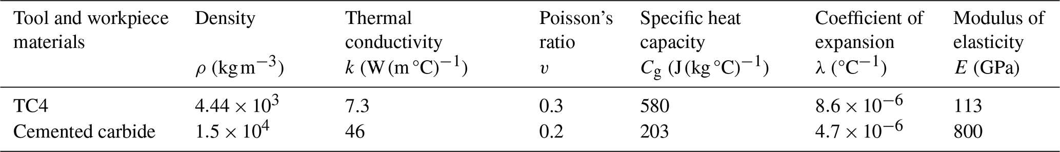
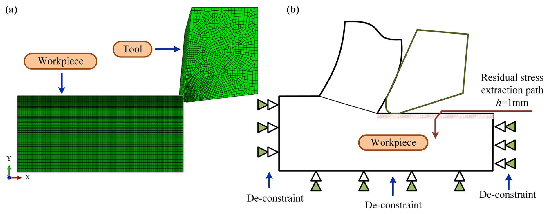
Figure 1Grid division and RS extraction path diagram. (a) Grid division. (b) RS extraction path diagram.
During the cutting process, intense friction occurs between the tool and the workpiece, including the friction between the front tool face and the flowing chip and between the rear tool face and the machined surface, as shown in Fig. 1b. For the contact interface between the front cutter surface and chips, it is generally believed that there are two parts: the bonding zone and the sliding zone. The friction factor has a significant influence on the simulation results. In the bonding region, the shear stress is fixed and equal to the material's yield stress. In the sliding region, the friction factor μ is constant. In this study, the friction factor μ=0.2 is selected and calculated based on the Coulomb friction model, which is expressed as
where τcrit is the shear stress, τ is the friction stress, and σ is the normal stress.
2.2 Reverse recognition of J–C constitutive model of TC4
The constitutive model of materials is the basis of finite-element model construction, and its accuracy has a decisive influence on the accuracy of finite-element simulation results. Plastic deformation and elastic deformation are two standard deformation modes of metal materials, and the constitutive model describes the deformation characteristics of materials. For a specific material, the constitutive model expresses the relationship between material strain, strain rate, and temperature through a series of equations with specific parameters and forms. Therefore, the study of material plastic behavior criteria is a key problem in finite-element simulation and theoretical prediction of cutting characteristics. Based on the concept of parameter optimization, this study combined the cutting experiment with material mechanics by using the reverse recognition method. It calculated the relevant variables by using the classic Oxley right-angle cutting model (see Fig. 2a). The parameters of the plastic constitutive model are obtained successfully through the iterative calculation process based on a genetic algorithm. Figure 2b shows the calculation flow of the plastic constitutive optimization model of a TC4 alloy.
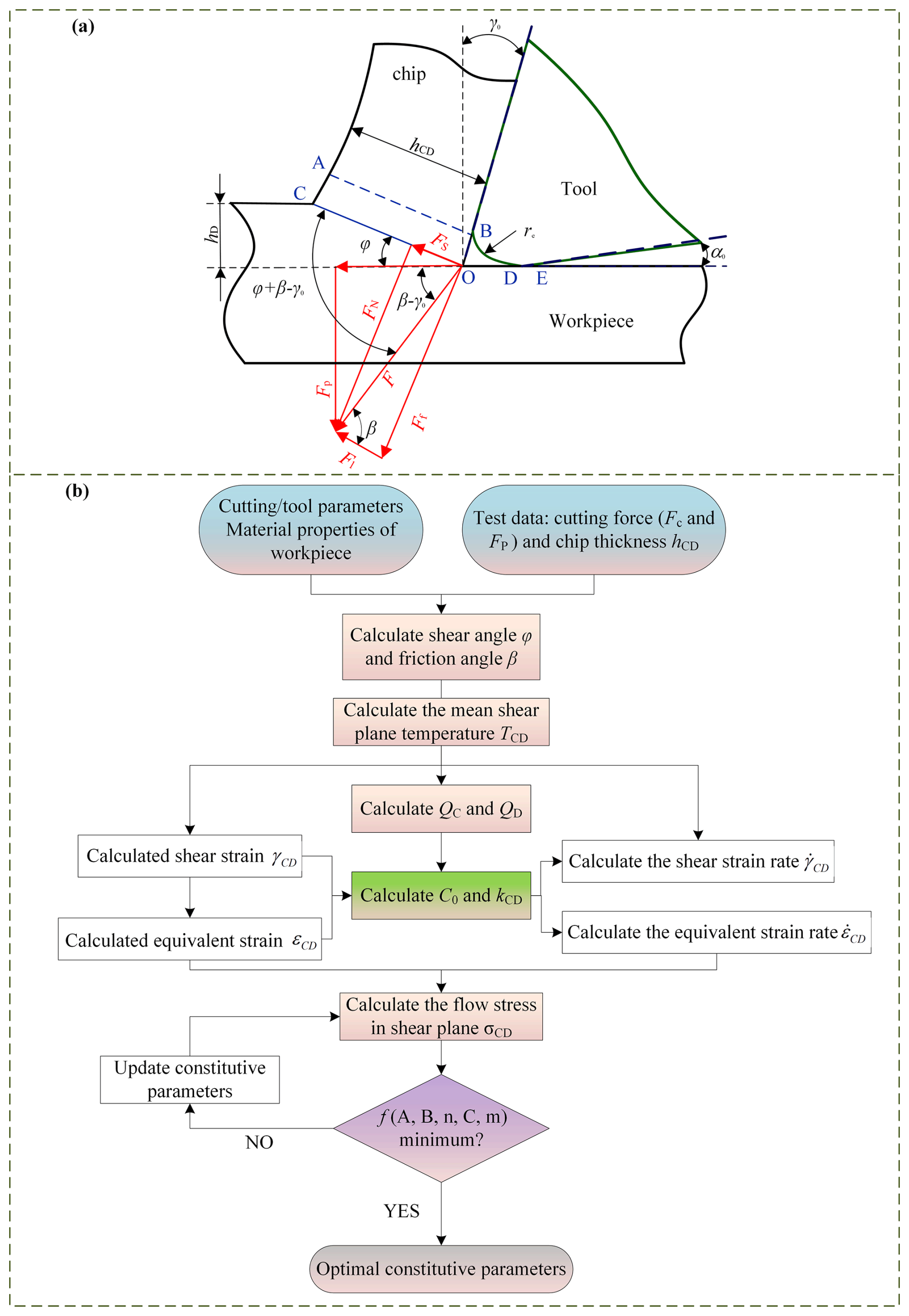
Figure 2J–C constitutive model optimization process. (a) Oxley's right-angle cutting model. (b) The calculation process of optimal parameters of a constitutive model.
The J–C constitutive model of the material is shown in Eq. (2):
where σCD is the shear equivalent flow stress; εCD is equivalent plastic strain; is equivalent strain rate; TCD is temperature; is the reference strain rate; Tg is the melting temperature of the workpiece material; Tw is the reference temperature, generally room temperature; A represents the yield strength of the material; B is the hardening modulus; C represents the strain rate sensitivity of stress; m is the heat softening factor; and n is the hardening factor. Thus, the model contains five undetermined coefficients.
Assuming that the strain distribution in the shear plane CD is uniform and the strain value is equal to half of the total strain in the first deformation region (Fig. 2a), the expression of the 60-shear strain can be obtained as follows:
where γ0 is the tool front angle and φ is the shear angle.
According to the von Mises yield criterion , and then the equivalent strain is
Assuming that the shear strain rate in the shear plane CD is uniformly distributed, if the strain rate is proportional to the shear rate and inversely proportional to the length of the shear plane CD, the shear strain rate can be expressed as
where vc is the cutting thickness, and .
According to the von Mises yield criterion , and then the equivalent strain rate is
where C0 represents the ratio of the length of the shear plane to the thickness of the shear zone, which changes with cutting conditions and can be obtained by the following equation:
where A, B, and n represent material parameters in the J–C model, QC and QD respectively represent hydrostatic pressure at points C and D, and kCD represents shear stress:
where Fc represents the main cutting force, FP represents the feed force, and bD represents the cutting width.
The average temperature TCD at the shear plane CD is , where
The amount of metal removal per unit time of mq is mq=ρvchDbD. Tw represents room temperature, η () represents the ratio of plastic work to total plastic work at the shear plane (ηTC4=0.9), ΔTxy represents the temperature rise in the plastic deformation zone, and α () represents the proportion of plastic work converted to the temperature rise of the workpiece. Its value can be obtained from the empirical formula of the blade:
where is the dimensionless calorific value, ρ is denoted the material density, ψ is denoted the specific heat capacity of the material, vc is denoted the cutting thickness, and M denotes the material's thermal conductivity.
Based on Oxley's theoretical calculation formula, the theoretical cutting forces and can be obtained, as follows.
Based on the idea of parameter optimization, this paper proposes a reverse identification method to solve the constitutive parameters of workpiece materials (Fig. 2b). This method will use a J–C constitutive model of six parameters, according to the known cutting condition and the test results, combined with the corresponding formula to calculate shear angle and friction angle of beta, strain epsilon CD, shear zone average temperature of TCD, and flow stress variables, such as εCD. Then Eqs. (13) and (14) can be used to obtain parameters in the theoretical cutting force and . The objective function is to minimize the root mean square error of the experimental cutting force (Fc, FP) and theoretical cutting force (, ), as shown in Eq. (15). By giving the initial values and search range of the five parameters in the J–C constitutive model and taking Eq. (15) as the objective function, the five parameters with the minimum objective function can be obtained by using genetic algorithm optimization, and then the J–C constitutive model suitable for the actual cutting process can be constructed.
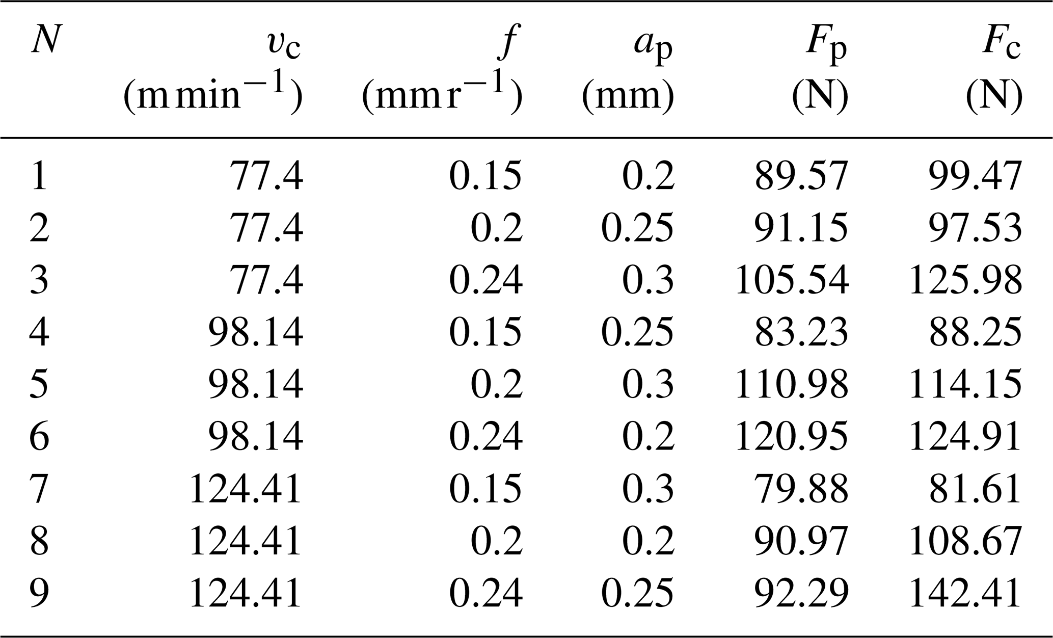
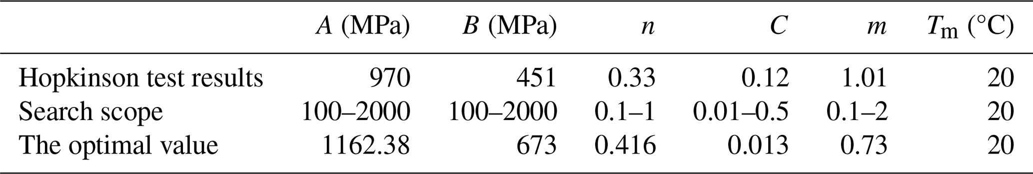
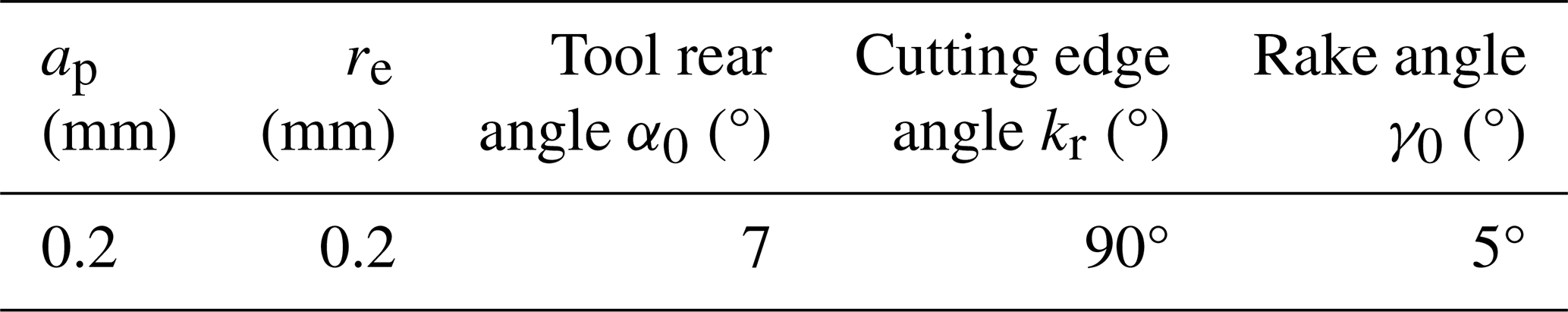
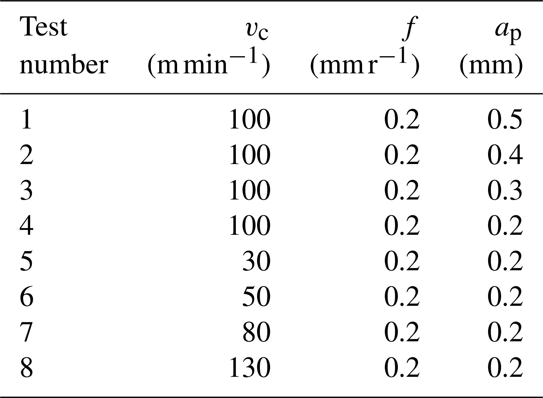
Taking A, B, n, C, and m in the J–C constitutive model as the coefficients to be determined, γ0, φ, σCD, β, hD, and bD were calculated according to the cutting experimental results and cutting parameters in Table 2 and combined with the above formulas. For details of the cutting test, see Sect. 3.1. The theoretical cutting forces and can be obtained by substituting these variables into Eqs. (13) and (14). At this point, the root mean square of the minimum error between the theoretical cutting force (, ) and the actual cutting force (Fc, FP) is taken as the objective function, as shown in Eq. (15). According to the initial parameter values and search, the range is given in Table 3. The optimized J–C constitutive model can be obtained by iterative calculation with Eq. (15) as the objective function, as shown in Table 3.
The genetic algorithm's parameters were set as follows: population size was 500, crossover probability was 0.7, mutation probability was 0.2, maximum iteration number was 800, maximum termination iteration number was 800, and fitness deviation was .
3.1 Experimental setup
The dry cutting experiment was carried out on the CNC lathe C5075, as shown in Fig. 3a. A three-phase cutting force measuring instrument was used during the cutting process to conduct the testing experiment. The experimental scheme is shown in Tables 4 and 5. After machining, the cutting surface's RS was studied using the stress analyzer (µ-x360s, the target material was a V target) based on the cos α method, as shown in Fig. 3b. The test parameters used are as follows: tube pressure is 30 kV, diffraction plane is (103), X-ray incidence angle is 23.8°, and diffraction angle is 140.15°. For each sample of cutting parameter, at least six random points were selected as the measurement positions of the sample test section, and the average value was taken as the final RS.
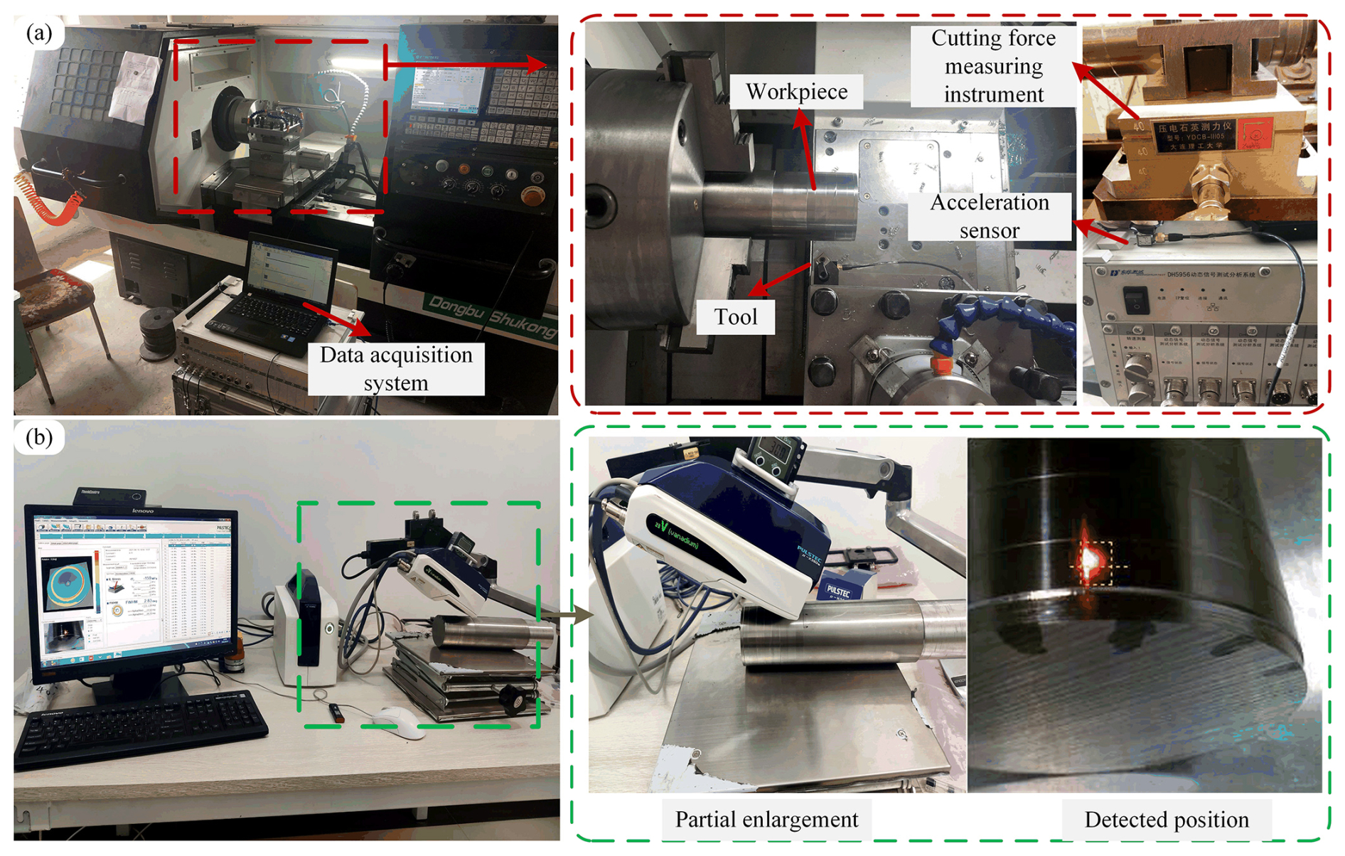
Figure 3Experimental setup. (a) Diagram of the cutting test setting. (b) RS detection test setting.
Table 4Setting of initial cutting parameters in finite-element simulation.
3.2 Validity test of simulation model
Figure 4a compares the RS results of finite-element simulation and test results before and after optimizing the J–C constitutive model. Although the results are error-prone, the variation trend is the same. The error of simulation results with the optimized constitutive model is less than without optimization. Figure 4b and c compare the cutting force and temperature derived from the finite-element simulation using the optimized J–C constitutive model and the corresponding experimental results. The model constructed in this study is highly consistent with the experimental data in predicting the cutting force and temperature during titanium alloy cutting, and the error range is controlled within 15 %. The results show that the model effectively simulates the cutting process of a titanium alloy. The workpiece's stress history and yield strength dictate the ultimate distribution of cutting RS. However, the actual load stress experienced by the workpiece material is a combination of the stress introduced during cutting and the initial stress. Measurement of RS on the surface of the uncut workpiece reveals an RS range of 10–15 MPa. Additionally, the heat generated during cutting can induce phase transitions in the surface material, further influencing RS. Consequently, some error inevitably exists in both test and simulation results.
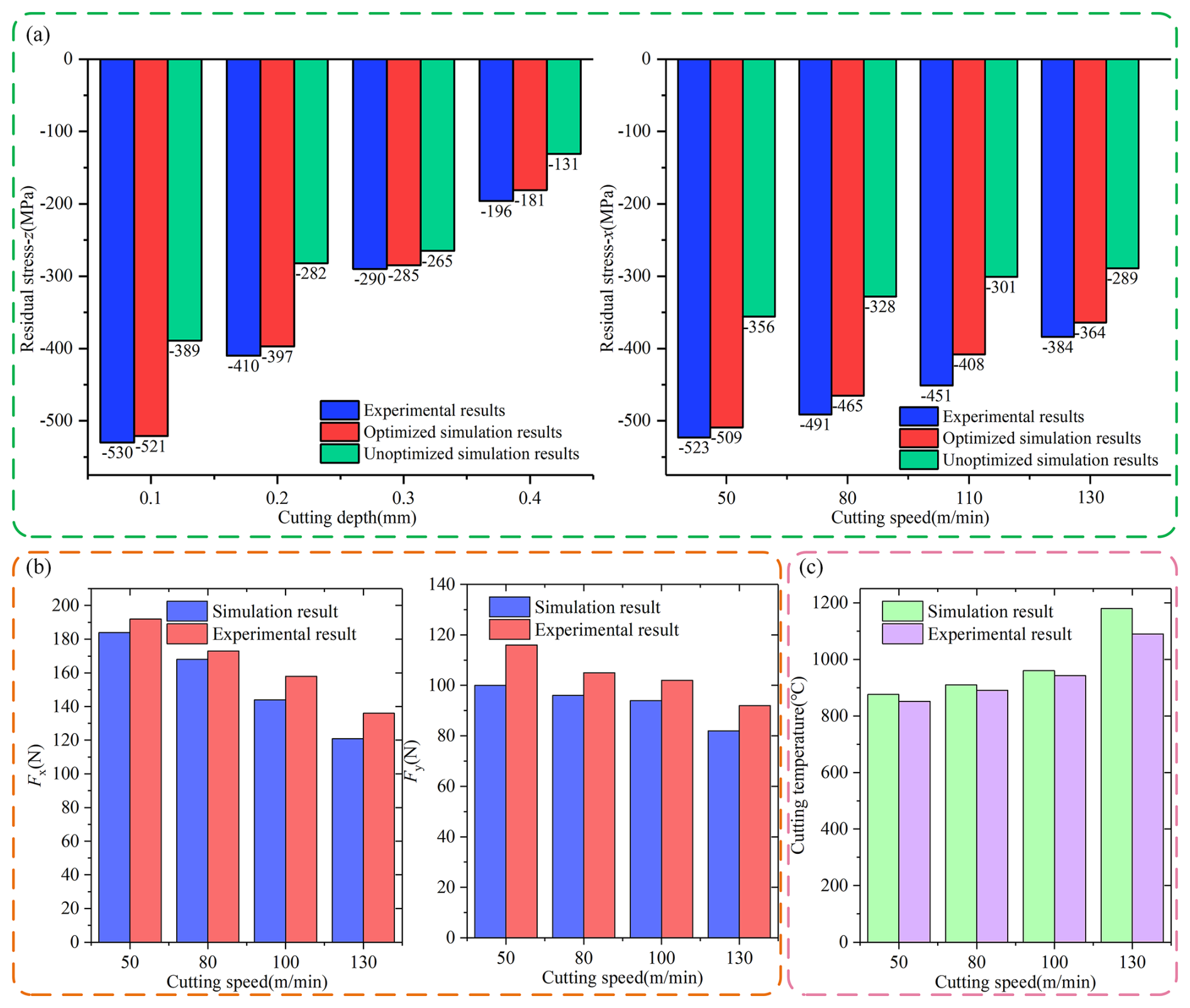
Figure 4Model verification result. (a) Verification of residual stress. (b) Verification of cutting force. (c) Verification of cutting temperature.
4.1 Analysis of the effect of cutting velocity on RS layer
The simulation chose four cutting velocities: 50, 80, 100, and 130 m min−1 while maintaining a constant cut thickness (ap) of 0.2 mm. The RS distribution at these different cutting velocities is shown in Fig. 5a. As shown in the figure, at the cutting velocity, the RS on the surface shifts towards reduced compressive stress or increased tensile stress. In contrast, RS in the subsurface tends to decrease tensile stress or increase compressive stress. With the increase in cutting velocity, the processing cycle can be shortened. Under the premise that the cutting thickness is maintained, the cooling time for the workpiece is shorter during faster cutting. This change increases the cumulative effect of heat during the cutting phase, which significantly increases the maximum surface temperature in the cutting area, as shown in Fig. 5b. Due to thermal expansion, the surface layer produces a compression effect under the reaction of the subsurface layer. The surface material will undergo plastic deformation once the temperature exceeds a certain critical point. Therefore, even if the surface layer temperature after processing falls back to average temperature, the original state of the surface layer is difficult to recover fully, and this continuous deformation is ultimately reflected in the residual surface tension. In addition, with the increase in the maximum temperature of the cutting area, the plastic deformation of the material caused by thermal expansion during the cutting process also increases correspondingly. After cooling to room temperature, the volume shrinkage of the surface material is more significant, which may cause the original compressive stress to be reduced or even transformed into tensile stress. Figure 5c shows the equivalent strain of the material surface at different cutting velocities. It can be seen that the degree of plastic deformation and the thickness of the affected layer increase with the increase in the cutting thickness.
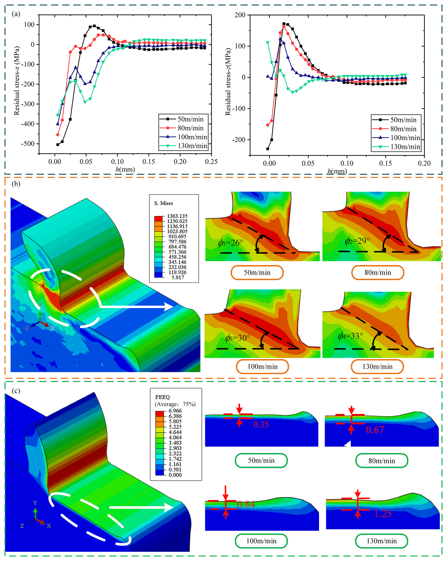
Figure 5Effect of cutting speed on RS, shear angle, and plastic strain layer. (a) Effect of cutting speed on residual stress. (b) Effect of cutting speed on shear angle. (c) Effect of cutting speed on plastic strain layer.
On the other hand, when the cutting speed is low, the shear angle is reduced, which will lead to an overall increase in the cutting force, but at this time, the cutting force component acting on the machining surface does not change much (Fig. 6a). As the cutting velocities increase, the force on the subsurface layer increases, increasing the thickness of the plastic stress layer on the machined surface, as depicted in Fig. 5c. The cutting force decreases with increasing cutting velocities, while the force acting on the machined surface shows an increasing trend as the angle increases shift. The compression effect of the workpiece matrix changes the RS state, which can cause a decrease in the tensile RS or an increase in the compressive RS.
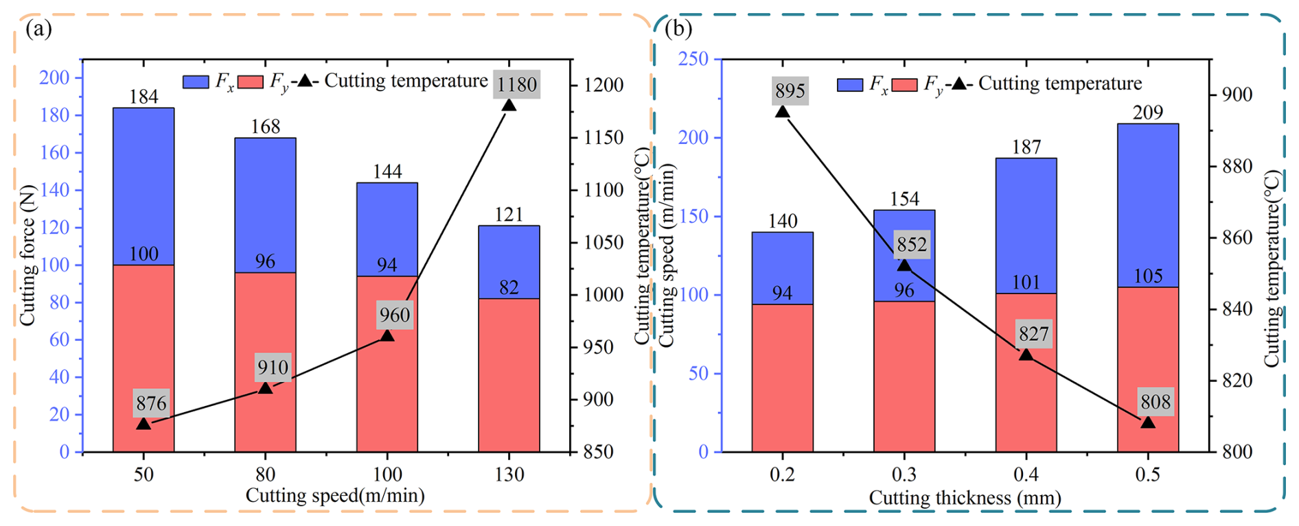
Figure 6Influence of cutting velocity and cutting thickness on cutting force and cutting temperature. (a) Effect of cutting speed on cutting force and cutting temperature. (b) Effect of cutting thickness on cutting force and cutting temperature.
4.2 Analysis of effect of cutting thickness on RS layer
Under the premise of maintaining a cutting thickness of , a simulation analysis was carried out for four different cutting thicknesses (ap), namely 0.2, 0.3, 0.4, and 0.5 mm. Figure 7a shows the results of residual surface stress distribution under different cutting thicknesses. The figure clearly shows a trend: with the increased cutting thickness, the RS in both directions presents an upward trend. In material processing, the cutting thickness greatly determines the layout of RS on the surface of the workpiece. Increasing the cutting area will cause the surface layer's original residual compressive stress to decrease until it becomes the residual tensile stress. At the same time, the subsurface layer shows tensile stress, and the stress increases with the increase in cross-sectional area. This change is mainly due to the inconsistency of heat release when the material is cut. In particular, when the cutting thickness is more pronounced, the material in the uncut area accumulates more heat, thereby increasing the temperature of the machining surface, as clearly shown in Fig. 7b. Consequently, during the subsequent cooling phase, the original surface compression state is weakened. It is possible to change to a tensile state.
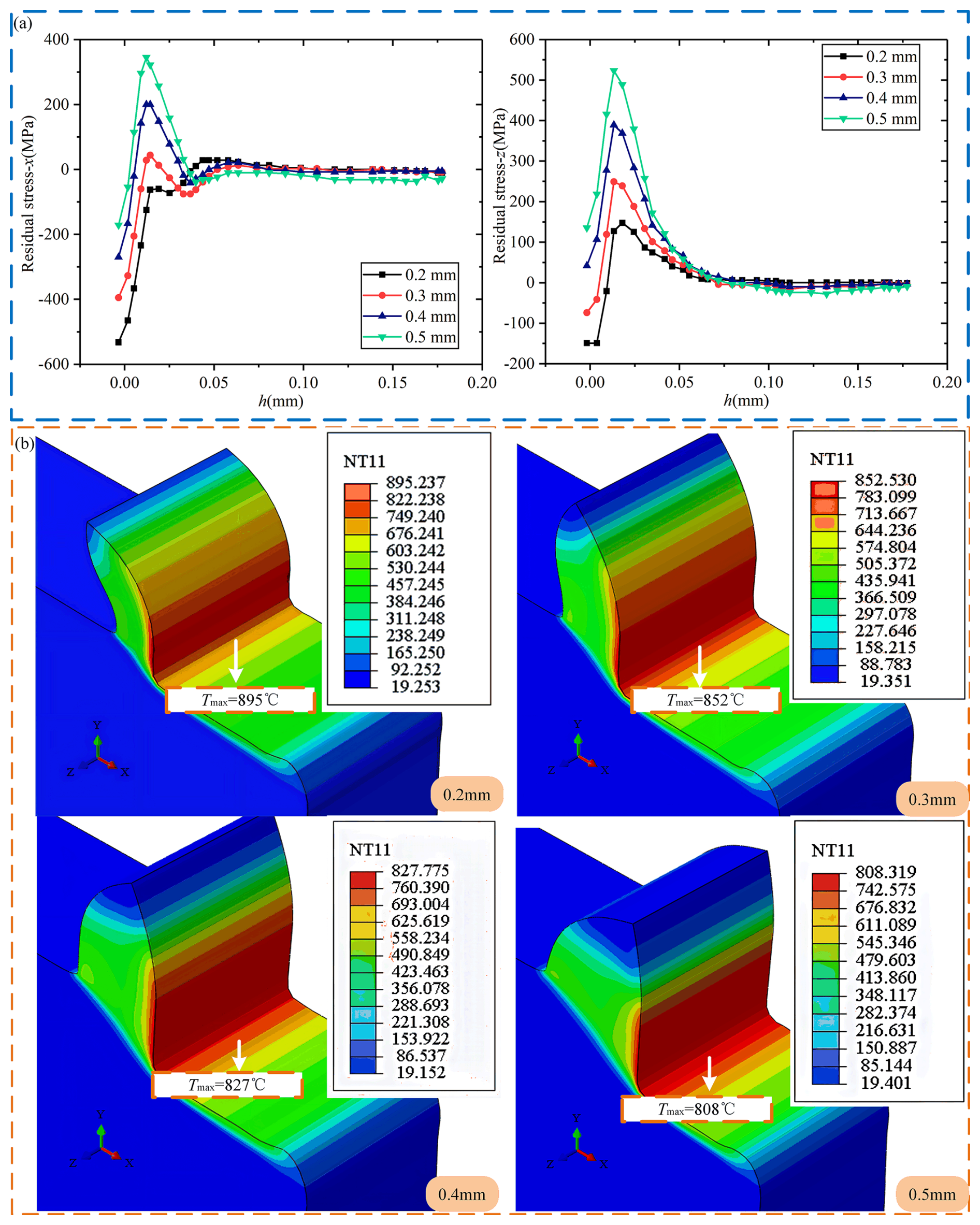
Figure 7Effect of cutting thickness on RS and surface temperature distribution. (a) Effect of cutting thickness on residual stress. (b) Effect of cutting thickness on surface temperature distribution.
In cutting operations, the fluctuation of cutting force is a crucial monitoring index. As the cutting thickness increases, the main cutting force Fx increases significantly, while the cutting force Fy acting on the machined surface is relatively stable, which is reflected in Fig. 6b. This phenomenon is because the increased cutting thickness means more material is removed, thus increasing the main cutting force. Despite this, the change in cutting force on the workpiece surface is insignificant. The increase in cutting thickness will undoubtedly increase the main cutting force. However, the uniform heat distribution during the machining process helps reduce the cutting force on the workpiece surface. At the same time, the RS distribution of the subsurface layer cannot be ignored. With the increase in cross-sectional area, the maximum temperature change in the main cross-sectional area becomes the critical factor affecting the RS distribution of the subsurface layer (Fig. 7b). With the increase in cross-sectional area, the variation trend of RS in the workpiece's surface layer and the subsurface layer tends to be the same. According to Yu et al. (2019), when the cutting depth is significant, the stress transfer and strain distribution within the material will change, resulting in the thickening of the plastic layer. The development of plastic deformation will further affect the distribution of residual stress. With the increase in the cross-sectional area, the variation trends of the residual stress in the surface layer and subsurface layer of the workpiece tend to become consistent. This may be because the larger cutting depth alters the propagation and attenuation characteristics of the stress wave within the material, thereby gradually synchronizing the stress responses at different depths, as described in Kolomy et al. (2024). The influence of cutting parameters on the residual stress distribution is a multi-factor coupled process involving the interaction of multiple factors, such as cutting force, cutting heat, and the mechanical properties of the material.
4.3 Sensitivity analysis of the effect of cutting velocities and cutting thickness on RS
In this paper, the distribution characteristics of RS in the x- and z-axis direction under different cutting conditions are discussed by linear regression analysis. The analysis results are presented as a response graph, which reveals the correlation between the cutting parameters and the residual surface stress, as shown in Fig. 8a. It is found that the effect of cutting thickness on the x-axis RS is much more significant than that of cutting velocity, indicating that the cutting thickness is a more critical variable in optimizing cutting parameters to reduce the x-axis RS. Adjusting the cutting thickness allows the RS in the x-axis direction to be controlled more effectively. Figure 8b shows the trend of z-axis RS with cutting thickness and cutting velocity. Further research shows that cutting thickness's effect on z-axis RS is more significant than cutting velocity. Therefore, when optimizing cutting parameters, special attention should be paid to the cutting thickness adjustment to effectively reduce the RS in the z-axis direction.
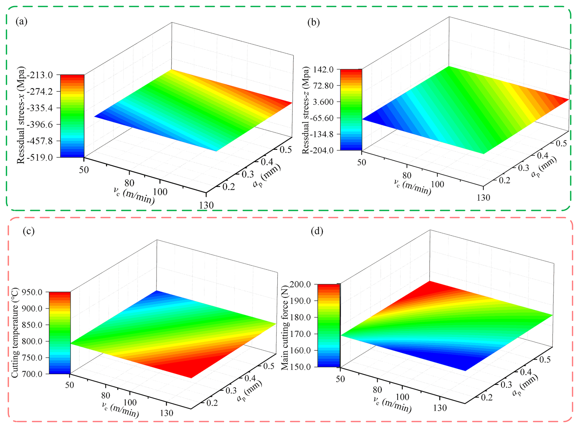
Figure 8Response of RS, cutting force, and temperature to changes in vc and ap. (a) Response of residual stress in the x direction to vc and ap changes. (b) Response of residual stress in the z direction to vc and ap changes. (c) Response of cutting force to changes in vc and ap. (d) Response of cutting temperature to changes in vc and ap.
Figure 8c reveals the main effect of cutting velocity on cutting heat generation. Higher cutting velocity will lead to more heat generation. However, this heat increase in the main cutting force is not significant; it directly impacts the material thermal expansion and cooling process, which in turn affects the RS distribution. Based on these findings, cutting heat reflects the effect of cutting velocity on RS. Therefore, in high-speed cutting operations, controlling the temperature during the cutting process is essential to reduce the potential impact of RS on the workpiece surface. Effective temperature control can reduce the generation of thermal stress and thus reduce RS. The comparison of Fig. 8d shows that the effect of cutting thickness on cutting heat and cutting force is opposite to that of cutting velocity. The increase in cutting thickness leads to a significant increase in cutting force, while the increase in cutting velocity has little effect on the cutting force. This opposite effect indicates that the interaction between cutting thickness and speed must be considered when optimizing cutting parameters.
In summary, the effect of cutting thickness on the RS of the x and z axis is significant, especially when optimizing cutting parameters to reduce the RS; cutting thickness is a more critical variable. The cutting velocity mainly affects the generation of cutting heat, while the cutting thickness significantly affects the cutting force. Therefore, in the actual processing, special attention should be paid to adjusting the cutting thickness and effective temperature control to reduce the potential impact of RS on the workpiece surface. Considering the cutting thickness and velocity, this optimization strategy can effectively improve materials' machining quality and mechanical properties.
5.1 Effect of tool front angle on RS layer
Four different sets of tool front angle values are used in the simulation, which are −5°, 0°, 5°, and 10°. The cutting velocity is 100 m min−1, and the thickness is 0.2 mm. Figure 9a shows the distribution of RS under different tool front angles. In the surface area, the internal stress is mainly caused by compressive forces. However, with the increase in the front angle of the tool, the RS in the subsurface region changes from the compressive state to the tensile state, especially in the z-axis direction. Nevertheless, changes in the tool front angle have less of an effect on the RS in the surface area, which can be attributed to two main factors.
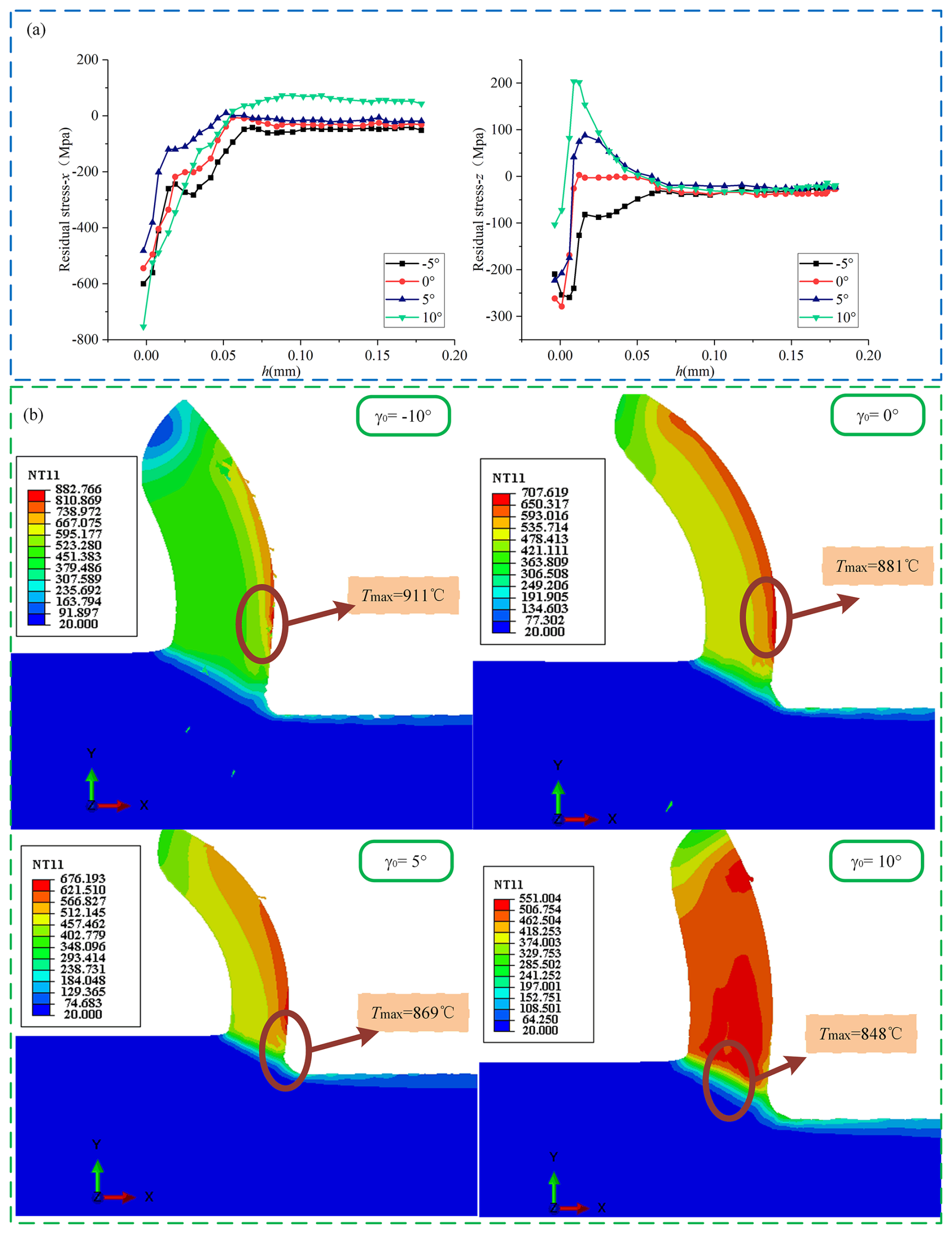
Figure 9RS and temperature distribution at different tool front angles. (a) Surface residual stress distribution of different tool front angles. (b) Temperature distribution of different tool front angles.
First, when the tool front angle is increased, the uncut layer material can be separated from the workpiece surface with less deformation, which helps to improve cutting efficiency. Increasing the tool front angle also reduces the contact area between the workpiece material and the tool front angle, thereby reducing the contact stress, reducing the friction between the workpiece material and the tool front angle, and reducing the temperature of the cutting area, as clearly shown in Fig. 9b. Secondly, with the increase in the front angle of the tool, the cutting force decreases significantly, which is reflected in Fig. 10a. It is assumed that the front angle of the tool is negative, which means that the tool is blunt. The front tool face pushes the raw material layer into the workpiece during cutting, resulting in more excellent cutting resistance. As the front angle of the tool increases, the tool becomes sharper. When the front angle of the tool is positive, the front surface of the tool will push the uncut layer material away from the direction of the workpiece, promoting the smooth separation of the uncut layer material from the workpiece surface, and the cutting resistance is relatively small. In addition, the influence of the tool front angle on RS is also related to the distribution of force during cutting. When the front angle of the tool is large, the distribution of cutting force is more dispersed, resulting in the change of stress state in the subsurface area. However, this change is not evident in the surface area, mainly because the surface area is affected by the cutting force and heat, and the change of the tool front angle has less of an impact on this part.
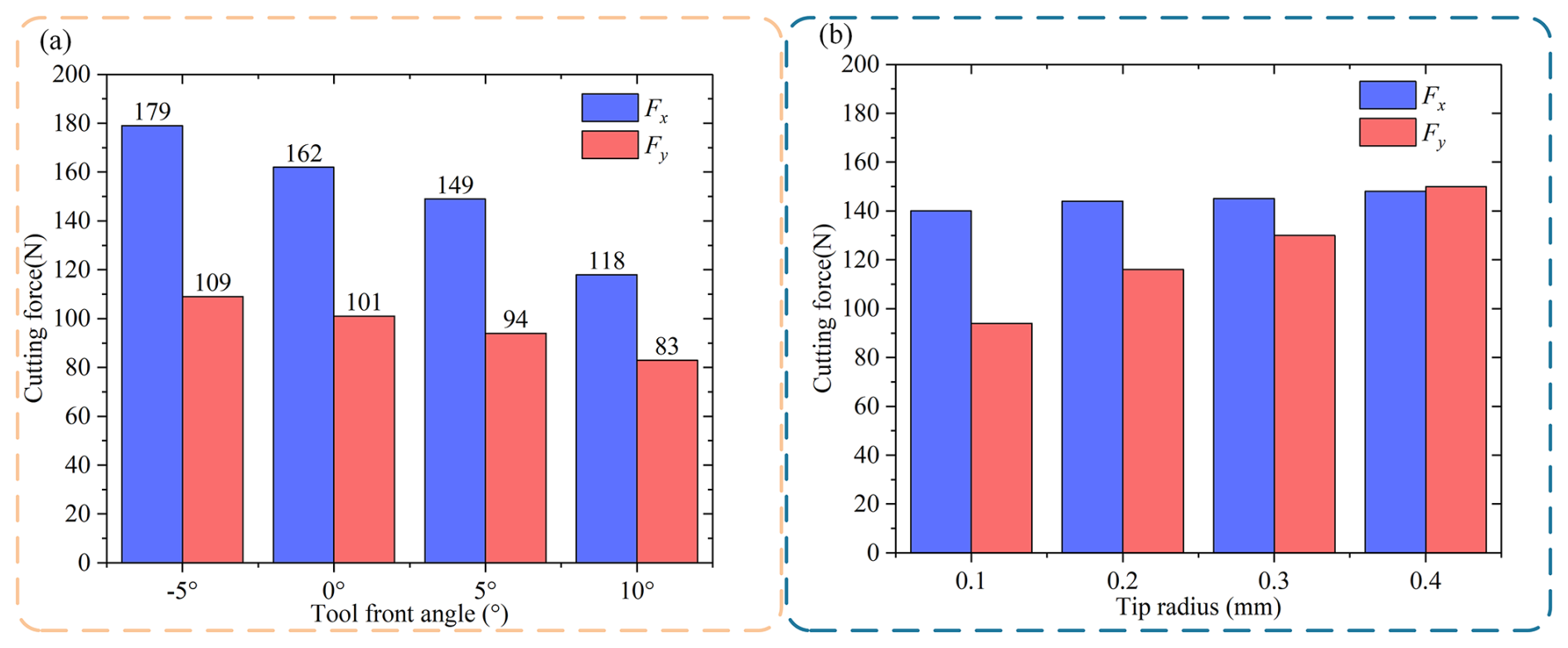
Figure 10The influence of tool front angle and tool corner radius on cutting force. (a) Cutting force varies with tool front angle. (b) Cutting force varies with tool corner radius.
The front angle of the tool is defined as the angle between the front tool face and the direction of the cutting thickness. When the front angle of the tool is raised, the maximum temperature and cutting force in the cutting area can be reduced. Increasing the front angle of the tool can enhance the cutting efficiency and reduce the heat and cutting temperature generated during the cutting process. At the same time, increasing the front angle of the tool can also reduce the extrusion effect of the tool on the workpiece, thus reducing the required cutting force. However, this effect is only equally significant in some cases. According to previous analysis, the RS caused by cutting temperature and cutting force shows an opposite trend. An increase in cutting temperature tends to reduce the RS, while an increase in cutting force increases the RS (Fig. 10a). Therefore, changing the tool front angle has almost no effect on the SRS due to the combined effect of cutting temperature and cutting force. This change mainly affects the subsurface layer's RS at the tool's front corner.
The limited downward diffusion ability to cut temperature has little influence on the RS of the subsurface layer, so the cutting force becomes the main influencing factor. With the increase in the front angle of the tool, the cutting force decreases, the compressive RS decreases, and the tensile RS increases. Under normal circumstances, when the tool front angle is positive, the surface finish of the obtained part is better than when the front angle is negative. A positive front angle reduces cutting force and temperature and improves machining quality. Therefore, it is recommended to use a tool with a positive front angle when machining to ensure the quality of the surface processing. In order to improve the fatigue life of the parts, the front angle of the tool can be appropriately reduced, ensuring the processing quality. By reducing the front angle of the tool, the cutting force on the part's surface can be reduced, thereby reducing RS and improving fatigue life.
5.2 Effect of tool back angle on RS layer
Three tool back angle groups, 5, 10, and 15°, are used for the simulation. The tool face angle is set at 5°, the cutting speed is maintained at 100 m min−1, and the cutting thickness is 0.2 mm. The final RS distribution is shown in Fig. 11a. From the analysis in Fig. 11a, it can be seen that changing the back angle of the tool has little effect on the RS distribution on the surface and subsurface of the workpiece. Meanwhile, changing the back angle of the tool has a relatively small effect on the cutting force and temperature in the cutting zone, as shown in Fig. 11b and c. It can be concluded that, in most cases, the influence of the back angle of the tool is minimal. On the surface, the RS distribution may be negligible. In terms of working conditions, experiments conducted by Meng et al. (2019) under varying cutting speeds and depths of cut have demonstrated that, regardless of the specific working conditions, the impact of the tool relief angle on overall machining performance, including RS distribution, cutting force, and temperature, remains limited. This further corroborates our simulation results, suggesting that the tool relief angle is not a dominant factor in determining the machining outcome under different working conditions.
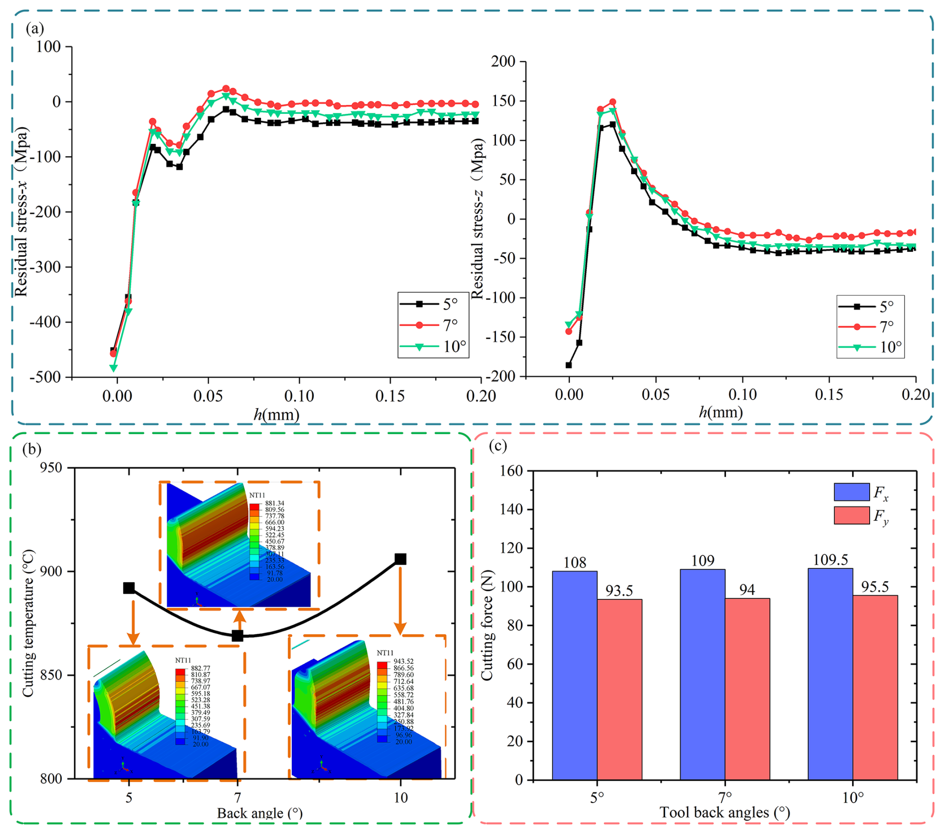
Figure 11SRS distribution, surface stress distribution, temperature change, and cutting force change at different tool back angles. (a) Surface residual stress distribution of different tool back angles. (b) Temperature distribution of different tool back angles. (c) Cutting forces vary with the back angle of the tool.
5.3 Analysis of the effect of tool corner radius on RS layer
In the simulation experiment, four different sizes of tool corner radius were selected, with specific values of 0.2, 0.4, 0.6, and 0.8 mm. In this process, the front and back angles of the tool are set to 5°, and the cutting parameters remain unchanged (, ap=0.2 mm). In Fig. 12a, the results show that the compressive RS on the workpiece surface decreases with the tool corner radius increase. This phenomenon is mainly due to the change in the cutting temperature, which is revealed by the temperature change chart shown in Fig. 10b. Although the maximum temperature change in the cutting area is not significant, the temperature of the workpiece cutting surface increases with the increase in the corner radius. Figure 12a also shows that the RS on the cutting surface changes from compression to tension and back to compression as the tool corner radius increases. This results in a decrease in tensile RS and a relative increase in compressive RS. This change of stress affects the formation of cutting force. The data in Fig. 10b further illustrate that as the size of the tool corner radius increases, the contact area between the tool and the workpiece also expands, increasing Fx and Fy. In particular, the growth of Fy is more significant, which enhances the compressive stress on the machined surface, directly leading to the reduction of tensile RS and the increase in compressive RS on the subsurface of the workpiece.
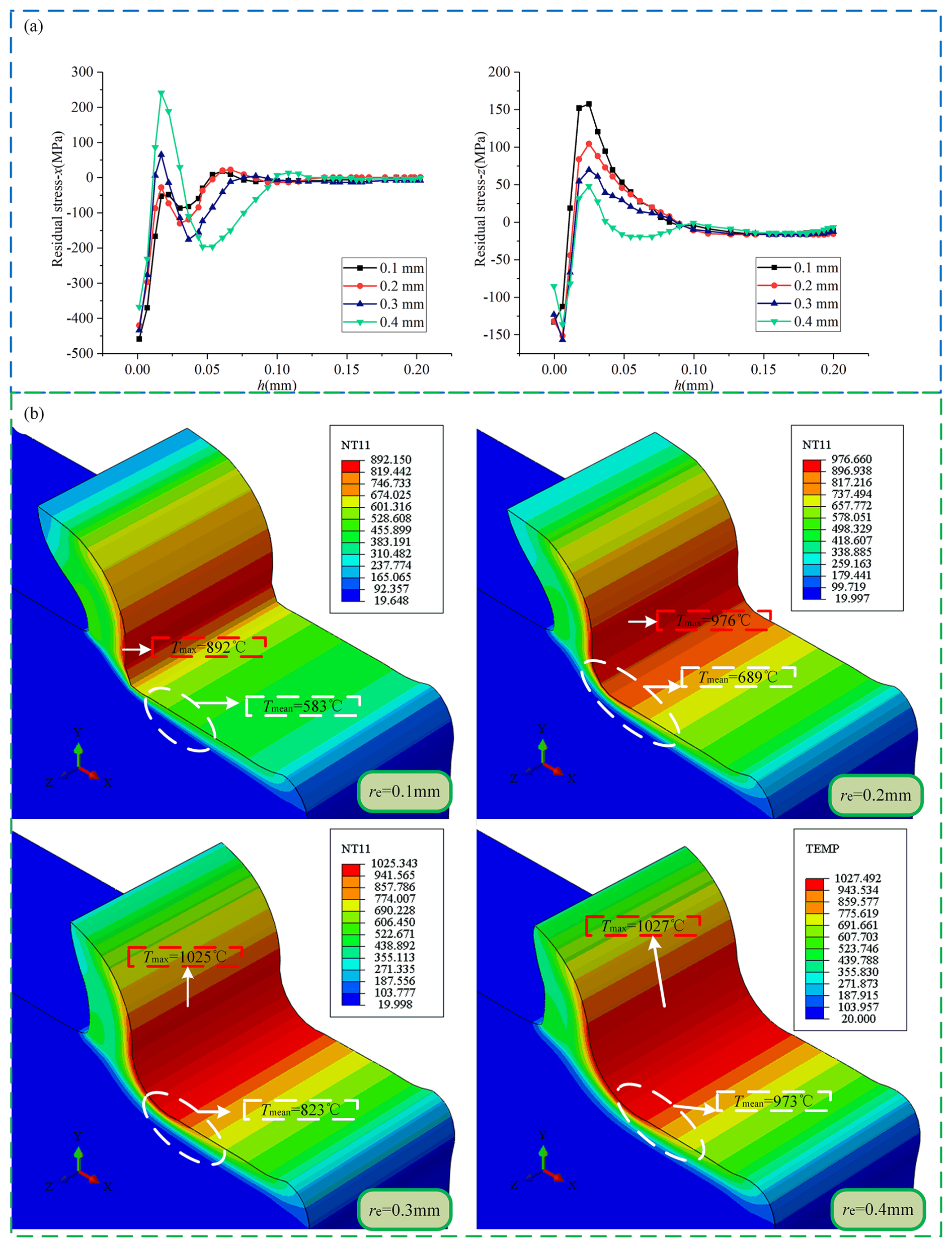
Figure 12SRS and temperature distribution with different tool corner radii. (a) Surface residual stress distributions of different tool corner radii. (b) Temperature distribution of different tool back angles.
5.4 Sensitivity analysis of the effect of tool front angle and tool corner radius on RS
From the above analysis, it can be seen that the change of the tool back angle has little influence on the cutting process, so the influence of the tool front angle and the tool corner radius is mainly discussed in terms of the response analysis of the tool angle to the RS. Figure 12a reveals the influence of tool front angle and corner radius adjustment on the change of x-axis RS. Image analysis shows that the influence of the tool front angle on x-axis RS is more significant than that of the tool corner radius. At the same time, the effect of the tool front angle on the RS in the z direction is more prominent than that of the tool corner radius. However, comparing the data in Fig. 12a, it can be inferred that the influence of the tool corner radius on the RS in the z direction is much more significant than its influence on the x direction. The comprehensive analysis results show that the tool's front angle and radius significantly influence the RS level. Figure 12b shows that γ0 significantly impacts Fx and Fy, but comparatively speaking, γ0 has a slightly more significant impact on Fx. When γ0 changes, the change of RS is mainly due to the change of cutting force, and the contribution of leading cutting force Fx to RS is undeniable. The re change has a negligible impact on Fx but a more significant impact on Fy. When re changes, the cutting force in the y direction, the plowing force, affects the RS. Therefore, to improve the machining accuracy, the geometric parameters of the tool should be selected reasonably to avoid generating RS.
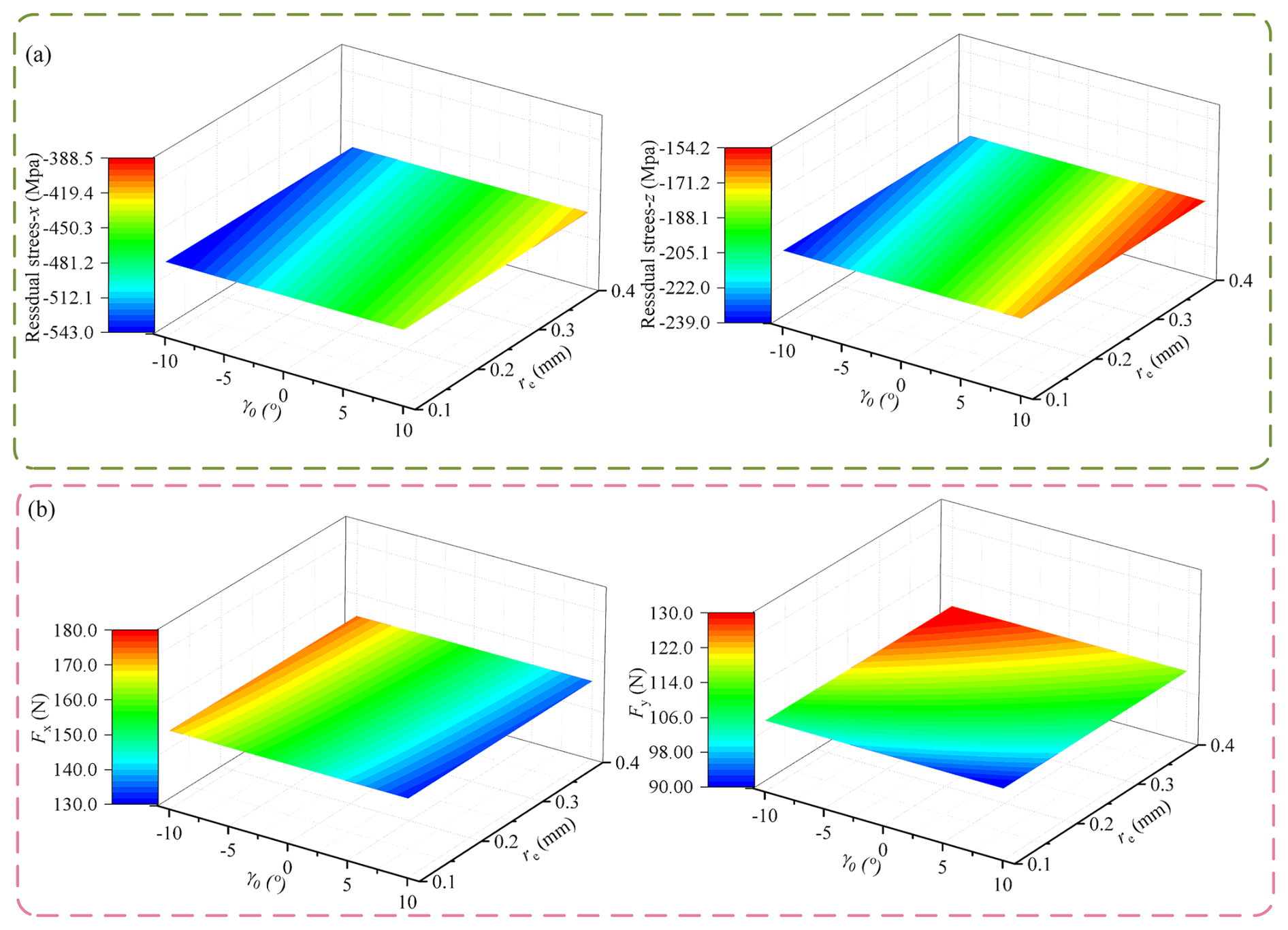
Figure 13Response of RS, cutting force and temperature to changes in re and γ0. (a) Residual stress response in the changes in γ0 and re. (b) Response of cutting force due to changes in γ0 and re.
In this study, a constitutive model of a TC4 titanium alloy is optimized by combining data-driven and genetic algorithm approaches, and experimental methods are used to verify the accuracy of the optimized model. Additionally, the effects of cutting parameters and tool angle on the SRS are also analyzed. Key findings from the study include the following.
-
Increasing the cutting velocity can reduce the cutting force and improve cutting conditions. However, this also causes the temperature of the cutting area to rise, which in turn increases the shear angle and the cutting force acting on the machined surface, thereby increasing the SRS and affecting the surface machining quality. Therefore, it is recommended to use a lower cutting velocity when processing titanium alloys. Additionally, as the cutting area increases, the residual compressive stress on the workpiece surface is reduced and may be transformed into residual tensile stress. Given this, a smaller cutting thickness should be preferred during processing.
-
When selecting the tool's front angle, a positive front angle can improve the surface machining quality compared with a negative front angle. However, a front angle that is too large may lead to an increase in SRS, which in turn affects the part's fatigue life. Therefore, when selecting the tool configuration, it is recommended to use a slightly positive front angle to improve the part's fatigue resistance.
-
Cutting temperature is the main factor determining the residual stress level of the workpiece surface, while cutting force is the key factor influencing the residual stress of the subsurface layer. The increase in cutting thickness significantly raises both cutting force and cutting heat simultaneously. Specifically, the rise in cutting force dominates the subsurface residual stress, whereas cutting heat mainly impacts the surface residual stress. This combined effect results in an increase in both surface and subsurface residual stress. The influence of tool angle on residual stress is primarily associated with the mechanical stress caused by variations in cutting force.
However, this study has some limitations. The experimental conditions may not cover all possible scenarios in titanium alloy machining. The model's parameters could be further refined with more diverse data. Also, the interaction between multiple cutting parameters can be more deeply explored.
In further work, more comprehensive experiments will be conducted to expand the database and improve the model's generalization ability. Advanced numerical simulation methods will be employed to better understand the complex mechanisms of titanium alloy machining. Additionally, the development of new cutting tools and coolants will be explored to enhance the machining performance of titanium alloys.
The data that support the findings of this study are available from the corresponding author upon reasonable request.
CW conceptualized the study and reviewed and edited the paper, CL was responsible for data curation and validation, ZT supervised the work, HM compiled the figures and tables, and WS checked the article.
The contact author has declared that none of the authors has any competing interests.
Publisher's note: Copernicus Publications remains neutral with regard to jurisdictional claims made in the text, published maps, institutional affiliations, or any other geographical representation in this paper. While Copernicus Publications makes every effort to include appropriate place names, the final responsibility lies with the authors.
The work was supported by the Science and Technology Program of Shenyang (grant nos. 24-102-6-05 and 24-102-6-06) and the National Natural Science Foundation of China (grant nos. 52075087 and U23B2098).
The work was supported by the Science and Technology Program of Shenyang (grant nos. 24-102-6-05 and 24-102-6-06) and the National Natural Science Foundation of China (grant nos. 52075087 and U23B2098).
This paper was edited by Jeong Hoon Ko and reviewed by two anonymous referees.
Chen, G., Caudill, J., Chen, S., and Jawahir, I. S.: Machining-induced surface integrity in titanium alloy Ti-6Al-4V: An investigation of cutting edge radius and cooling/lubricating strategies, J. Manuf. Process., 74, 353–364, https://doi.org/10.1016/j.jmapro.2021.12.016, 2022.
Hassaan, A. M. and Han, Y. S.: A Finite Element Analysis on the Effect of Scanning Pattern and Energy on Residual Stress and Deformation in Wire Arc Additive Manufacturing of EH36 Steel, Materials (Basel, Switzerland), 16, https://doi.org/10.3390/MA16134698, 2023.
Hou, M., Mou, W., Yan, G., Song, G., Wu, Y., Ji, W., Jiang, Z., Wang, W., Qian, C., and Cai, Z.: Effects of Different Distribution of Residual Stresses in the Depth Direction on Cutting Performance of TiAlN Coated WC-10wt%Co Tools in Milling Ti-6Al-4V, Surface and Coatings Technology, 397, 125972, https://doi.org/10.1016/j.surfcoat.2020.125972, 2020.
Ju, K., Duan, C., Sun, Y., Shi. J., Kong, J., and Abdolhamid, A.: Prediction of machining deformation induced by turning residual stress in thin circular parts using ritz method, Journal of Materials Processing Tech., 307, https://doi.org/10.1016/J.JMATPROTEC.2022.117664, 2022.
Kuo, C., Chen, C., Jiang, S., and Chen, Y.: Effects of the Tool Geometry, Cutting and Ultrasonic Vibration Parameters on the Cutting Forces, Tool Wear, Machined Surface Integrity and Subsurface Damages in Routing of Glass-Fibre-Reinforced Honeycomb Cores, J. Manuf. Process., 104, 59–75, https://doi.org/10.1016/j.jmapro.2023.08.051, 2023.
Kolomy, S., Maly, M., Sedlak, J., Jan, Z., Martin, S., Pavel, H., and Karel, K.: Machinability of Extruded H13 Tool Steel: Effect of Cutting Parameters on Cutting Forces, Surface Roughness, Microstructure, and Residual Stresses Machinability of Extruded H13 Tool Steel: Effect of Cutting Parameters on Cutting Forces, Surface Roughness, Microstructure, and Residual Stresses, Alexandria Engineering Journal, 99, 394–407, https://doi.org/10.1016/J.AEJ.2024.05.018, 2024.
Li, M., Zhao, W., Li, L., He, N., and Stepan, G.: Influence of milling stability on machined surface integrity and fatigue performance of Ti-6Al-4V titanium alloy, Eng. Fail. Anal., 109103–109103, https://doi.org/10.1016/j.engfailanal.2024.109103, 2025.
Oliveira, A. R., Jardini, A. L., and Del, E. G.: Effects of Cutting Parameters on Roughness and Residual Stress of Maraging Steel Specimens Produced by Additive Manufacturing, Int. J. Adv. Manuf. Tech., 111, 2449–59, https://doi.org/10.1007/s00170-020-06309-3, 2020.
Meng, L., Maen, A., Aqib, M. K., Su, Y., Fang, C., Zhang, H., and He, N.: Prediction of residual stresses generated by machining Ti6Al4V alloy based on the combination of the ALE approach and indentation model, J. Braz. Soc. Mech. Sci., 41, 1–15, https://doi.org/10.1007/s40430-019-1914-5, 2019.
Paillard, M., Rossi, F., Hélène, E. B., Poulachon, G., Ritou, M., and Maury, N.: Effects of the Tool Microgeometry on Thermo-Mechanical Loads for Ti-6Al-4V Finishing Cutting Operations, Procedia CIRP, 133, 442–447, https://doi.org/10.1016/J.PROCIR.2025.02.076, 2025.
Santhakumar, S., Zhang, Z., Zi, W. T., and Yi, F. C.: Non-Contact Measurements of Residual Stress Distribution and Grain Size in Titanium Alloys with Laser Ultrasonic System, Int. J. Mech. Sci., 264, 108809, https://doi.org/10.1016/j.ijmecsci.2023.108809,2024.
Srivastava, M., JayakumarV, Y., and Nag, A.: Additive manufacturing of Titanium alloy for aerospace applications: Insights into the process, microstructure, and mechanical properties, Applied Materials Today, 102481–102481, https://doi.org/10.1016/J.APMT.2024.102481, 2024.
Tan, R., Zhang, X., Zou, S., Guo, X., Hu, S., Zhen, J., and Sun, T.: Study on ultra-precision processing of Ti-6Al-4V with different ultrasonic vibration-assisted cutting modes, Mater. Manuf. Process., 34, 1380–1388, https://doi.org/10.1080/10426914.2019.1660788, 2019.
Wang, Z. and Sun, Y.: Influence of micro-milling machining parameters on residual stresses in alumina bioceramics-a three-dimensional finite element simulation study, PloS one, 19, e0313588, https://doi.org/10.1371/JOURNAL.PONE.0313588, 2024.
Yue, Q., He, Y., Li, Y., and Tian, S.: Investigation on effects of single- and multiple-pass strategies on residual stress in machining Ti-6Al-4V alloy, J. Manuf. Process., 77, 272–281, https://doi.org/10.1016/j.jmapro.2022.03.013, 2022.
Yue, C., Hao, X., Ji, X., Liu, X., and Yan, F.: Analytical Prediction of Residual Stress in the Machined Surface during Milling, Metals, 10, 498–498, https://doi.org/10.3390/met10040498, 2020.
Yu, L., Quan, Y., Liu, P., and Wan, J.: Influence of Turning Parameters on Surface Integrity of D840 Wheel Material, J. Phys. Conf. Ser., 1213, 052112 (6pp), https://doi.org/10.1088/1742-6596/1213/5/052112, 2019.
Zhang, C., Wang, L., Meng, W., Zu, X., and Zhang, Z.: A Novel Analytical Modeling for Prediction of Residual Stress Induced by Thermal-Mechanical Load during Orthogonal Machining, Int. J. Adv. Manuf. Tech., 109, 475–89, https://doi.org/10.1007/s00170-020-05594-2, 2020.
- Abstract
- Introduction
- Construction of the RS model
- Materials and experimental procedures
- Effect of cutting parameter on RS
- Effect of tool angle on RS layer
- Conclusions
- Data availability
- Author contributions
- Competing interests
- Disclaimer
- Acknowledgements
- Financial support
- Review statement
- References