the Creative Commons Attribution 4.0 License.
the Creative Commons Attribution 4.0 License.
 | 21 Jul 2025
Vibration responses of a two-span three-support rotor system with sliding bearing elevation change
Ziyang Zhou
Guangfu Bin
Chao Li
Yaozhi Gao
Maharaja Bayjid Md
The two-span three-support rotor is a typical structure in rotating machinery such as steam turbines and water pumps. The alteration in bearing elevation can result in oil film instability, rotor rub impact, and other malfunctions. In extreme cases, this can cause excessive wear of couplings and other components, leading to accidents. This study derives the dynamic equation of a two-span three-support rotor that accounts for variations in bearing elevation. Meanwhile, the influence of different sliding bearing elevations on the misalignment excitation of the coupling and the stiffness damping coefficient of the bearing is considered, and the vibration response of each bearing is also investigated. Corresponding experiments are designed and conducted to validate the findings. The findings indicate that after raising the elevation of bearing 3 from 1.5 to 2 mm, the amplitude of the fundamental frequency (1×) at bearing 2 is reduced by 438 %, whereas the amplitude at the second harmonic (2×) is increased by 128 %. This increase in misalignment excitation causes the axis orbit of disk 1 to change from a crescent shape to a petal shape. This study offers theoretical insights and empirical data that may assist in the structural design and fault diagnosis of two-span three-support rotors.
- Article
(8115 KB) - Full-text XML
- BibTeX
- EndNote


The two-span three-support rotor structure is commonly utilized in rotating machinery, including turbine units, compressor units, and pumps, and is typically supported by sliding bearings (G. Bin et al., 2018). This structure is characterized by a limited number of bearings, straightforward design, and significant vibration coupling properties. Factors such as thermal expansion of the bearing seat, wear of the bearing pads, or foundation settlement can lead to changes in the elevation of sliding bearings, which in turn affects the alignment of the rotor (Bin et al., 2023; Ming et al., 2015; Wang et al., 2022b; Xu et al., 2018). Alterations in bearing elevation may also result in oil film instability, rotor rubs, and excessive wear of components such as bearings and couplings (Cui et al., 2019; Li et al., 2019; Zhao et al., 2021; Bin et al., 2018b). Furthermore, the nonlinear characteristics of sliding bearings can complicate the vibration response of the rotor system when bearing elevation changes occur (Li et al., 2018; Sun et al., 2020). Consequently, investigating the effects of changes in sliding bearing elevation on rotor vibration characteristics is critically important for the structural design and fault diagnosis of rotating machinery, including turbine units, compressors, and pumps.
When the elevation of sliding bearings is altered, the alignment of couplings is consequently affected, resulting in misalignment excitation. Research indicates that over 70 % of failures in rotating machinery are associated with rotor misalignment (Simm et al., 2016; Wang et al., 2021). Numerous studies have been conducted on the vibrational effects of misalignment in both rigid and flexible couplings. In the context of rigid couplings, Al-Hussain and Redmond (2002) derived the excitation forces resulting from parallel misalignment, identifying this phenomenon as a potential source of lateral excitation. Lees (2007) examined the spectral characteristics of rotor systems equipped with rigid couplings, discovering that misalignment produces a 2× frequency component. Fan et al. (2020) noted that misalignment in gear couplings results in the emergence of 2×, 3×, and 4× frequency components, with the 2× component becoming more pronounced as the measurement points approach the gear coupling node. Li and Yu (2001) reported that misalignment excitation in gear couplings leads to the generation of even harmonics of the 1× frequency within the rotor's spectral characteristics. Xiao et al. (2022) found that misalignment in spline couplings manifests in the frequency spectrum with components at 1×, 2×, 6×, 8×, and 10×. Miao et al. (2024) observed that the spectral characteristics of rotors under coupling misalignment exhibit 1×, 2×, 3×, and 4× frequency components; however, the 3× and 4× components are less pronounced in cases of angular misalignment. Generally, When rigid couplings undergo misalignment, their spectral analysis typically reveals fundamental (1×) and second-harmonic (2×) frequency components. However, the differences in the structure of the rigid coupling result in variations in the higher-frequency components generated under conditions of misalignment. Recent advancements in materials science and mechanical engineering have facilitated the development of various flexible couplings, which provide enhanced shock resistance and improved displacement compensation, thereby contributing to their increased prevalence in practical applications. Saavedra and Ramírez (2004a, b) found that the vibrational response of misaligned flexible couplings is closely linked to the stiffness of the coupling. Avendano and Childs (2013) identified a 2× frequency component in the spectral characteristics of diaphragm coupling misalignment. Zhang et al. (2023) reported that misalignment in disk couplings results in the presence of higher-order harmonic components within the rotor's frequency domain response. Xia et al. (2019) determined that parallel misalignment in hexagonal couplings is characterized by a dominant 2× frequency, whereas angular misalignment is primarily associated with a 3× frequency component. Chen et al. (2019) observed that radial misalignment in diaphragm couplings leads to a D-shaped rotor orbit, while angular misalignment produces a combination of S- and D-shaped orbits. Sawalhi et al. (2019) noted that misalignment in jaw couplings generates 1× and 3× frequency components. Mehta et al. (2024) demonstrated that certain misalignment angles can significantly amplify the vibration amplitude of jaw couplings. Desouki et al. (2020) found that parallel misalignment in flexible helical couplings predominantly manifests as a 2× frequency in the spectrum, while angular misalignment displays both 2× and 4× components. In summary, the current body of research predominantly emphasizes the effects of coupling misalignment on rotor vibration characteristics, while the relationship between variations in bearing elevation and coupling misalignment remains largely unexplored.
Due to the structural differences inherent in rotors, considering only the misalignment vibration characteristics of the coupling is insufficient to reflect the vibration behavior of rotors with different structures. Lu et al. (2021) studied the vibration characteristics of a single-span rotor system. Zhang et al. (2020) observed that as the angular misalignment increases, the rotor's axis orbit gradually changes from a linear shape to a mesh-like diamond shape. Wang et al. (2022a) examined the impact of bearing misalignment on the vibration characteristics of a single-span rotor, noting that combined misalignment mainly causes changes in the rotor's 2× frequency. El-Mongy and Younes (2018) discovered that under misalignment, the rotor vibration signal shifts significantly from the zero position. Nan et al. (2024) found that angular misalignment does not change the characteristic frequency amplitude of a dual rotor, while the characteristic frequency of offset misalignment is mainly excited by parallel misalignment. Ma et al. (2023) found that under angular misalignment in a single-span rotor, the rotor spectrum displays frequencies of 1×, 2×, 3×, and 4×. Wang and Gong (2019) investigated the force spectrum characteristics of a dual-span rotor under parallel misalignment. Hu et al. (2023) analyzed the vibration response characteristics of a dual-span rotor under misalignment conditions. Patel and Darpe (2009) found that the axis orbit of a dual-span rotor under parallel misalignment shows an inner figure-eight shape, while under angular misalignment, it shows an outer figure-eight shape. Zigang et al. (2016) found that as rotor uncertainty increases, the amplitude band of misalignment in dual-span rotors becomes wider. Tuckmantel and Cavalca (2019) found that when angular misalignment occurs in a dual-span rotor, a strong 3× frequency signal appears at the disk. Wan et al. (2012) found that under coupled misalignment, a series-connected rotor exhibits multiple-frequency components such as 2×, 3×, and 4×, and the amplitude of 2× vibration decreases as the distance between the measurement point and the coupling increases. Pennacchi (2012) found that when misalignment occurs in a multi-span rotor, the rotor spectrum reveals frequencies of 1×, 2×, 3×, and 4×, with the 2× frequency being the most sensitive to misalignment changes. Ma et al. (2015) found that misalignment reduces the vibration amplitude in a two-span three-support cantilever rotor. From the above, it can be seen that different types of couplings and rotor structures lead to variations in the misalignment vibration characteristics of rotor systems.
In summary, there exists a paucity of research concerning the effects of variations in sliding bearing elevation on the vibration characteristics of two-span three-support rotors. Therefore, this study seeks to fill this gap through theoretical derivation, simulation analysis, and experimental testing. The structure of the remainder of this paper is organized as follows: Sect. 2 explores the impact of elevation changes on the rotor system, deriving the dynamic equations for a two-span three-support rotor while accounting for sliding bearing elevation. This section also elucidates the methods for characterizing coupling misalignment excitation as well as bearing stiffness and damping under varying elevation conditions. Section 3 examines the vibration characteristics of the rotor at different elevations and rotational speeds, thereby clarifying the influence of sliding bearing elevation on the rotor's vibration response and axis orbit. Section 4 provides a detailed account of the design of the two-span three-support rotor test bench and outlines the vibration testing procedures conducted under various elevation conditions. This section further validates the model by comparing the spectral amplitudes obtained from experimental and simulation results. Finally, the research conclusions are presented, accompanied by a discussion of potential future research directions.
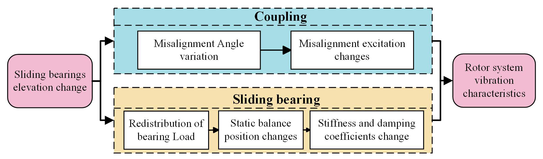
In the process of formulating the dynamic equations for a two-span three-support rotor that incorporates the effects of bearing elevation, it is essential to first examine the influence of bearing elevation on rotor misalignment excitation as well as on bearing stiffness and damping. Variations in the elevation of sliding bearings can result in a redistribution of loads among the bearings, which in turn affects their stiffness and damping coefficients. Furthermore, alterations in bearing elevation may impact the alignment of the coupling, thereby modifying the magnitude of the misalignment excitation. The coupling effects of changes in stiffness and damping coefficients, along with misalignment excitation, significantly influence the vibrational characteristics of the rotor system. The mechanism through which changes in bearing elevation affect the rotor system is illustrated in Fig. 1.
2.1 Rotor system dynamics equation
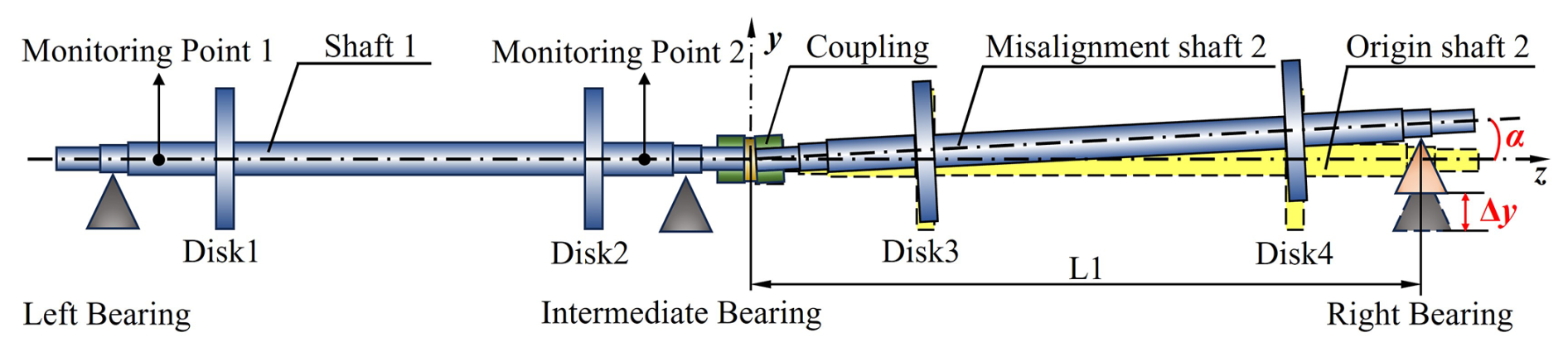
The focus of this study is a two-span three-support rotor system, as illustrated in Fig. 2. This system is supported by three oil-lubricated hydrodynamic bearings, with two shafts interconnected by an elastic coupling, and each shaft is equipped with two disks. The generalized equation of motion for the rotor system is articulated as follows (Kumar and Tiwari, 2021; Lal, 2021; Longkai et al., 2016):
In Eq. (1), M denotes the mass matrix of the rotor system, C represents the damping matrix of the system, Ω indicates the rotational speed of the rotor, G is the gyroscopic matrix, K signifies the stiffness matrix, and Q(t) represents the loads acting on the rotor system. By neglecting the axial motion of the rotor, the variable q(t) can be characterized using 4 degrees of freedom, which correspond to the displacements and angular displacements in the X and Y directions. This can be articulated as follows:
The impact of changes in the elevation of the sliding bearing on the rotor is depicted in Fig. 1. Fluctuations in elevation lead to a redistribution of the loads borne by each bearing, which in turn affects the alignment of the coupling and modifies the extent of the misalignment excitation. The coupling effects of these factors ultimately result in alterations to the vibration characteristics of the rotor system. The mathematical representation of the load vector Q(t) acting on the rotor system under these conditions is as follows:
In Eq. (2), FG denotes the gravitational force acting on the rotor system, FH represents the bearing oil film force, and FM indicates the excitation resulting from coupling misalignment. Both the bearing oil film force and the coupling misalignment are dependent on the change in elevation, denoted as Δy.
2.2 Misalignment excitation characteristics
In the context of a two-span three-support rotor system, alterations in the elevation of the sliding bearings can lead to angular misalignment, thereby affecting the coupling. The relationship between the angular misalignment of the two shafts is illustrated in Fig. 2. This study aims to quantify the angular misalignment in the coupling resulting from variations in bearing seat elevation while intentionally disregarding the parallel misalignment induced by these elevation changes. Let L1 denote the distance from the center of the right bearing to the center of the coupling, and let Δy represent the elevation change in the left bearing. The misalignment angle, denoted as α, of the coupling can be approximated as follows:
The elastic coupling is a type of flexible coupling that facilitates both angular and displacement compensation through the use of elastic components. In the presence of angular misalignment within the rotor coupling, it can be conceptualized as a universal joint transmission (Saavedra and Ramírez, 2004a). The transmission relationship between the two shafts can be articulated as follows:
In Eq. (4), the variable α signifies the skew angle between axis 1 and axis 2, while ω2 represents the rotational speed of axis 2, and ω1 indicates the rotational speed of axis 1. By differentiating Eq. (4) with respect to time, we derive the following expression:
Utilizing Newton's second law, one can derive the relationship among torque, angular acceleration ε, and moment of inertia J of a rotating axis:
Ty represents the alternating torque in the horizontal direction induced by the deflection angle α. The generation of Ty may lead to misalignment vibrations. As illustrated in the torque relationship diagram in Fig. 2, it is evident that
By applying the Fourier transform to Eq. (7), we obtain the following results:
In this equation, an and bn represent the coefficients of the Fourier series expansion, and their respective formulas are provided as follows:
From Eq. (8), it is evident that a functional relationship exists between the bearing elevation Δy and the misalignment excitation Ty. As the bearing elevation varies, the coupling misalignment excitation Ty will correspondingly adjust, thereby influencing the magnitude of the misalignment excitation within the rotor system.
2.3 Bearing dynamics equation
When the bearing elevation changes, the load W on the sliding bearing varies, leading to a shift in the static equilibrium position of the journal, which in turn causes changes in the bearing's stiffness and damping coefficients. This paper employs the three-moment method to calculate the loads at each bearing under varying elevation conditions, uses the finite-difference method to solve for the static equilibrium position of the bearing, and applies the perturbation method to determine the stiffness and damping coefficients of the bearing. The flow of the bearing oil film is analyzed using the Reynolds equation. In this study, it is assumed that the fluid is in a normal operating condition, isothermal, laminar, and incompressible. Thus, the Reynolds equation for unsteady conditions in oil-lubricated hydrodynamic bearings can be expressed as follows (Ma et al., 2021; Xie et al., 2024):
In Eq. (10), p represents the pressure within the fluid film, h is the oil film thickness, μ is the absolute viscosity of the lubricant, ω denotes the angular velocity of the journal, R is the bearing radius, t is time, θ is the circumferential coordinate of the bearing, and z is the axial coordinate of the bearing.
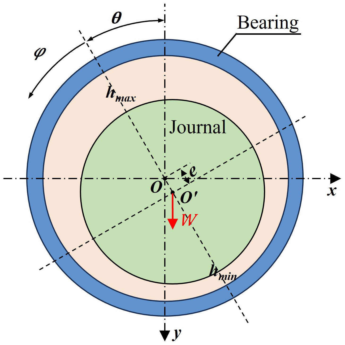
The coordinate relationship between the journal and the bearing in this paper is shown in Fig. 3. When the elevation of the sliding bearing changes, the load W borne by the rotor system's bearings is redistributed. Since there is a corresponding relationship between the load magnitude and the static equilibrium position of the sliding bearing, the oil film thickness equation h at the static equilibrium position can be regarded as a function with the elevation change Δy as the variable, which is shown by
In this context, c represents the radial clearance of the bearing, e is the eccentricity in the center plane, and θ denotes the circumferential coordinate of the oil film. Substituting Eq. (12) into Eq. (11) yields the oil film pressure distribution P′ at the equilibrium position, allowing for the calculation of the bearing load in the X and Y directions as follows:
After performing a Taylor expansion at the static equilibrium position of the sliding bearing and retaining the linear terms, the load expression can be obtained as follows:
The stiffness and damping coefficients of the bearing can be expressed using the partial derivatives of the forces near the equilibrium position:
From Eqs. (11)–(14), it can be seen that when the bearing elevation changes, the oil film thickness h and the oil film pressure P′ at the static equilibrium position of the bearing are affected. This, in turn, influences the calculation of the oil film forces in the X and Y directions, ultimately impacting the bearing's stiffness and damping coefficients.
From Eqs. (1) and (8), it can be observed that when the elevation of the sliding bearing changes, the misalignment torque Ty will vary, thereby affecting the magnitude of the excitation Q(t). Additionally, from Eqs. (1) and (11)–(13), it can be seen that changes in bearing elevation cause corresponding changes in the bearing's static equilibrium position, which leads to variations in stiffness and damping. This, in turn, affects the damping coefficient C and stiffness coefficient K on the left side of Eq. (1), ultimately influencing the displacement q(t) of the rotor system.
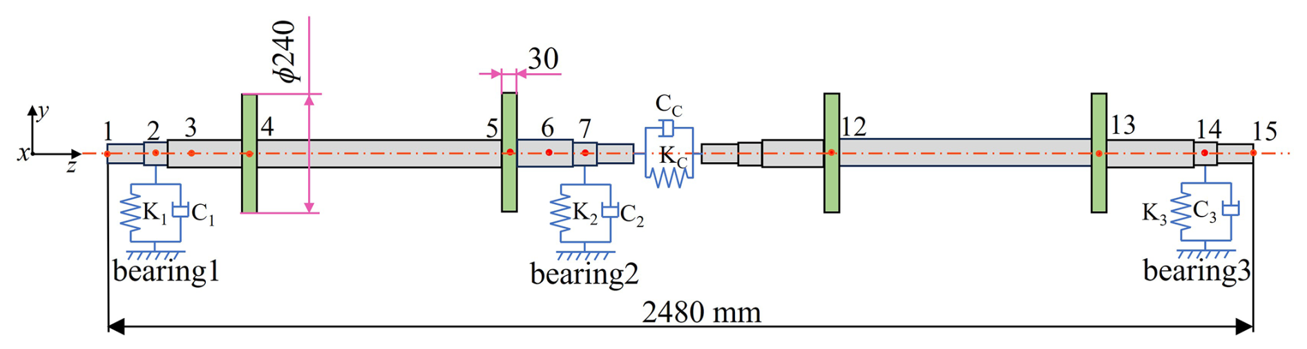
In this study, a specific type of two-span three-support rotor system is examined, with a total rotor length of 2840 mm. This study examines a system comprising four disks, each possessing identical geometric dimensions, specifically a diameter of 240 mm and a thickness of 30 mm. A rotor dynamics model has been developed utilizing the Timoshenko beam element theory. The sliding bearings, which have a diameter of 45 mm and a radial clearance of 0.06 mm, utilize ISO-46 as the lubricant. The three bearings are strategically positioned at nodes 2, 7, and 14, respectively, and are modeled with stiffness damping for equivalent representation. The four disks are situated at nodes 4, 5, 12, and 13, respectively, and are modeled using the concentrated mass method for equivalent purposes. The coupling is a critical connecting element in the rotor system. In this study, it is modeled as a spring-and-damper system, where the connection between the two shafts is established through the input of radial and lateral stiffness and damping coefficients. The dynamics model of the system is illustrated in Fig. 4. This paper employs the Newmark β numerical integration method to solve the dynamics Eq. (1) of the rotor system, thereby facilitating the determination of the displacement q(t) of the two-span three-support rotor.
3.1 Rotor vibration at different speeds
Changes in rotational speed can affect the stiffness and damping coefficients of bearings, thereby altering the dynamic characteristics of the rotor and subsequently affecting its vibration performance. At low speeds, misalignment excitation has a significant impact on the vibration characteristics of the two-span three-support rotor. Therefore, the operating speed range below the first critical speed of the two-span three-support rotor (900–2100 rpm) is selected for analysis. When the rotor elevation reaches 2 mm, the vibration characteristics exhibit noticeable misalignment features. Thus, 2 mm is chosen as the bearing elevation for the analysis. Through the analysis of vibration characteristics at different speeds, the time domain waveforms for each bearing, specifically under the condition of a 2 mm elevation for bearing 3, have been obtained, as illustrated in Fig. 5. At 900 rpm, the wave height is observed to be the highest at bearing 2 and the lowest at bearing 3. When the speed increases to 1200 rpm, the frequency of misalignment excitation approaches the natural frequency of the bearing, resulting in system resonance; this causes the time domain waveform to transition from a single-peak to a multi-peak shape. At this juncture, the wave height remains the highest at bearing 2, while it is the lowest at bearing 1. As the speed further increases to 1500 rpm, the wave height is the largest at bearing 2 and the smallest at bearing 3, with a slight spike becoming evident in its time domain waveform.
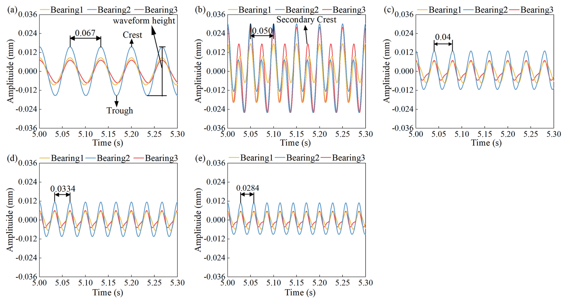
Figure 5Time domain plots of the bearing at different speeds: (a) 900 rpm, (b) 1200 rpm, (c) 1500 rpm, (d) 1800 rpm, and (e) 2100 rpm.
A spectrum analysis was conducted on a two-span three-support rotor at different rotational speeds, with the results illustrated in Fig. 6. When the elevation of bearing 3 is set to 2 mm, the spectral characteristics of the rotor exhibit both 1× and 2× frequency components. As the speed increases, the stiffness and damping of the sliding bearing undergo changes, which in turn affect the dynamic characteristics of the rotor. The amplitude of the 1× frequency at each bearing exhibits a W-shaped trend, characterized by an initial decrease, followed by an increase, a subsequent decrease, and a final increase. Specifically, the amplitude initially decreases, subsequently increases, decreases again, and finally increases once more. The amplitude of the 2× frequency displays a slanted N-shaped trend, characterized by an initial increase, followed by a decrease, and then a subsequent increase. When the rotational speed attains 1200 rpm, the amplitude of the rotor's 2× frequency increases significantly. Since the natural frequency of the two-span three-support rotor is 37.31 Hz, the 2× frequency of the misalignment excitation is 40 Hz at a speed of 1200 rpm, which results in a deviation of 6.7 % from the rotor's natural frequency. As the 2× frequency is close to the rotor's natural frequency, it falls within the resonance zone, leading to a significant increase in the amplitude at the 2× frequency. An analysis of the 1× and 2× frequency amplitudes across the bearings reveals that bearing 2 exhibits the highest amplitude for the 1× frequency, while bearing 3 demonstrates the lowest. Conversely, for the 2× frequency, bearing 3 shows the highest amplitude, whereas bearing 1 has the lowest. Specifically, the peak values for the 1× and 2× frequencies are as follows: for bearing 1, 0.0083 and 0.014 mm, respectively; for bearing 2, 0.015 and 0.018 mm; and for bearing 3, 0.0068 and 0.022 mm. When compared to the peak values of the 1× frequency, the peak values of the 2× frequency for bearings 1, 2, and 3 are higher by 68.7 %, 20 %, and 224 %, respectively. This phenomenon can be attributed to the fact that, with an elevation of 2 mm, bearing 2 experiences the largest load and possesses the highest stiffness, resulting in the highest amplitude for the 1× frequency. In contrast, bearing 3, situated in the single-span rotor section, has the lowest stiffness and is the most susceptible to the effects of misalignment excitation, leading to the smallest amplitude for the 1× frequency and the largest amplitude for the 2× frequency. When the speed increases from 900 to 1050 rpm, the 1× frequency amplitude at bearings 1, 2, and 3 decreases by 29.7 %, 25.0 %, and 28.3 %, respectively. When the speed increases from 1200 to 1350 rpm, the 2× frequency amplitude at bearings 1, 2, and 3 decreases by 106.7 %, 95.9 %, and 100.0 %, respectively.
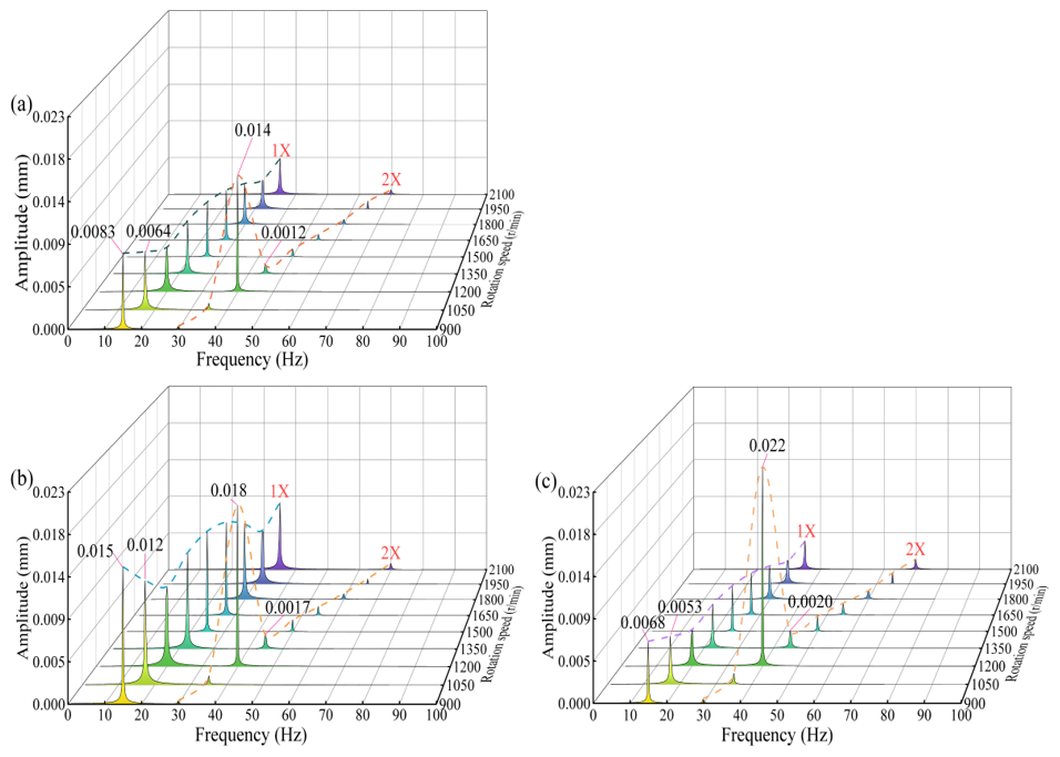
Figure 6Spectrum characteristics of the bearings at variable speeds: (a) bearing 1, (b) bearing 2, and (c) bearing 3.
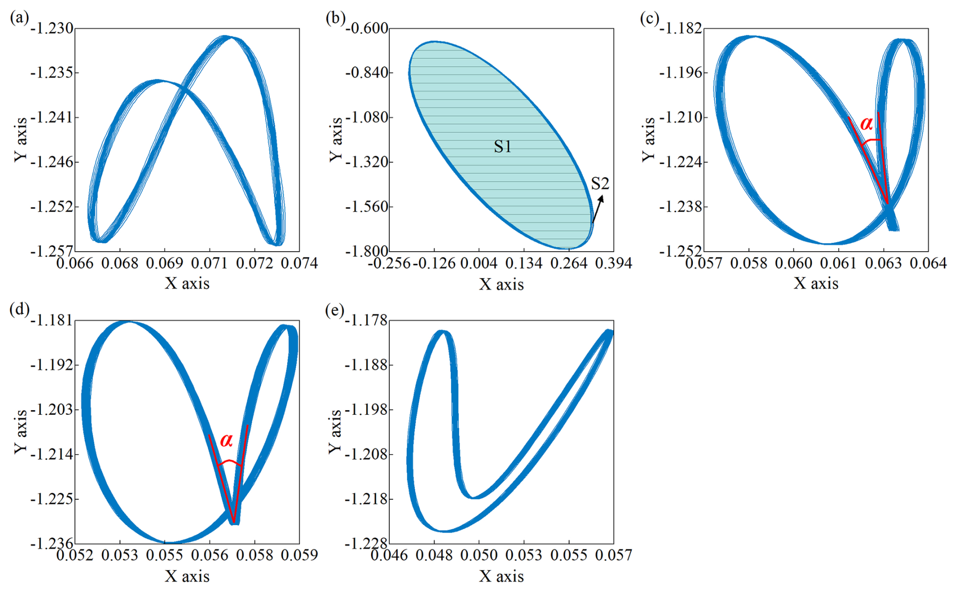
Figure 7Axis orbit of disk 1 at different speeds: (a) 900 rpm, (b) 1200 rpm, (c) 1500 rpm, (d) 1800 rpm, and (e) 2100 rpm.
In two-span three-support rotor systems, the stiffness of the single-span shaft section differs from that of the two-span shaft section, leading to distinct axial orbits for the disks located on each shaft section. This study examines a scenario in which the elevation at bearing 3 is set to 2 mm, focusing on the orbits of disk 1 in the two-span shaft section and disk 4 in the single-span shaft section, with the results illustrated in Figs. 7 and 8. For disk 1, as the rotational speed increases, the orbit progressively converges toward the origin, and the orbit area progressively decreases. At a rotational speed of 900 rpm, the orbit of disk 1 presents in the shape of the Arabic number eight. When the speed increases to 1200 rpm, the rotor resonates, and the axis orbit area reaches its maximum, exhibiting a petal-like shape, with the core area S1 occupying the main part. At 1500 rpm, the displacement range of the orbit remains relatively constant; however, the angle α between the two petals gradually increases. Upon further increasing the speed to 2100 rpm, the orbit transforms into a crescent shape, and the orbit area is further reduced.
In the case of disk 4, the shaft segment is located on has fewer supports and lower stiffness, making it more susceptible to misalignment excitation. At a rotational speed of 900 rpm, the axis orbit appears to be petal-shaped, with the petal area (S2) being the predominant component. Upon increasing the speed to 1200 rpm, the rotor encounters resonance, resulting in the maximum area of the axis orbit, where the core area (S1) emerges as the dominant feature, while the petal area nearly disappears. As the speed escalates from 1200–1500 rpm, a decrease in the core area (S1) is noted, accompanied by an increase in the petal area (S2), which leads to an overall area of the axis orbit shrinking. When the speed rises to 1800 rpm, due to the nonlinear characteristics of the bearings, the oil film's resistance to interference strengthens, causing the axis orbit to change from a petal shape to a crescent shape. At a speed of 2100 rpm, the orbit of disk 4 presents the shape of the Arabic number eight. Overall, as the rotational speed increases, the stiffness of the bearings improves, the impact of misalignment excitation diminishes, and the axis orbit tends toward a low misalignment. The axis orbit of disk 1 gradually evolves into a crescent shape, while disk 4 progressively transitions into the shape of the Arabic number eight.
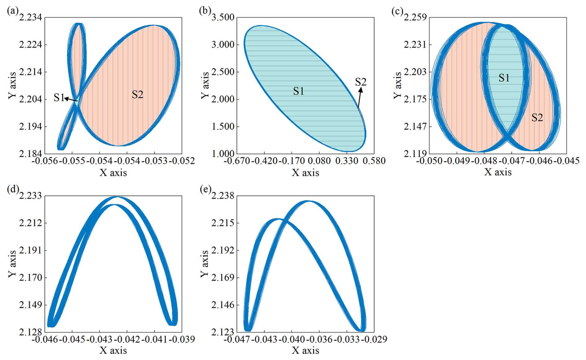
Figure 8Axis orbit of disk 4 at different speeds: (a) 900 rpm, (b) 1200 rpm, (c) 1500 rpm, (d) 1800 rpm, and (e) 2100 rpm.
3.2 Rotor vibration at different elevations
By examining the vibrational characteristics of the rotor at various rotational speeds, it was found that the amplitude of the 2× frequency is particularly significant at 1200 rpm. Consequently, a constant rotational speed of 1200 rpm was selected to investigate the operational conditions across different elevation levels. Six distinct elevations were analyzed, i.e., 0, 1, 1.5, 2, 2.5, and 3 mm, to assess the time domain variations at the three sliding bearings as the elevation changes, with the results shown in Fig. 9. The time domain diagrams of the rotor at varying elevations indicate that changes in elevation do not affect the period T of the time domain waveform. As the elevation of bearing 3 increases, the time domain waveform progressively shifts from a single peak to a multi-peak configuration. At an elevation of 0 mm, the wave height at bearing 2 is the highest, while it is the lowest at bearing 3. When the elevation is increased to 1 mm, the wave height at bearing 3 becomes the highest, whereas it is the lowest at bearing 1. At elevations of 2 mm and above, the wave height at bearing 2 is again the highest, while it remains the lowest at bearing 1. As the elevation of the bearings increases, the load on the bearings is altered, resulting in changes to stiffness and damping coefficients. With the gradual increase in elevation, the impact of misalignment excitation on the rotor system intensifies. When the elevation reaches 2 mm, the time domain waveform transitions into a multi-peak shape. Furthermore, as the elevation continues to increase, the height of the time domain waveform also progressively rises.
A spectrum analysis was conducted on the rotor at different elevation levels while operating at 1200 rpm, and the spectral characteristics at each bearing position were documented, as shown in Fig. 10. It is evident from Eq. (8) that the change in elevation will result in the generation of excitation characterized by even-order frequency misalignment. As the elevation of bearing 3 increases, the 1× frequency component in the rotor's spectral characteristics exhibits a trend of initial increase followed by a decrease and then a subsequent increase. Conversely, the 2× frequency component exhibits a consistent upward trend. This is due to the influence of elevation changes on the stiffness and damping at the bearings and the misalignment excitation at the coupling. In the aligned state, bearing 2 bears the highest load. As the elevation of bearing 3 rises, the loads on bearings 1 and 3 increase, while the load on bearing 2 diminishes. This redistribution of load results in changes in stiffness and damping characteristics, which affect the rotor's 1× frequency. Simultaneously, as the elevation variation Δy increases, the misalignment excitation intensifies, leading to a gradual increase in the amplitude of the rotor's 2× frequency.
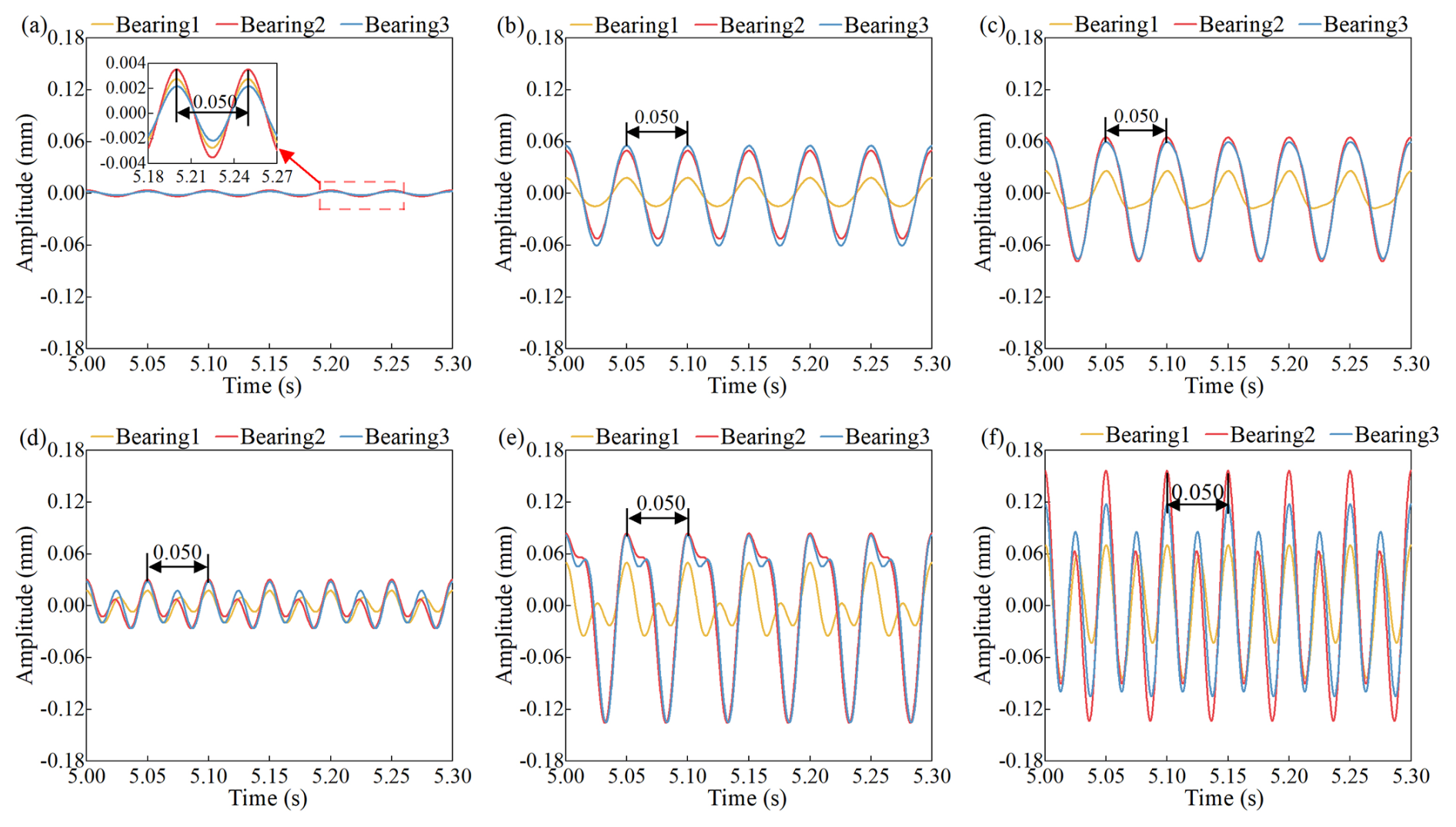
Figure 9Time–frequency characteristics of the rotor at various elevations: (a) 0 mm, (b) 1 mm, (c) 1.5 mm, (d) 2 mm, (e) 2.5 mm, and (f) 3 mm.
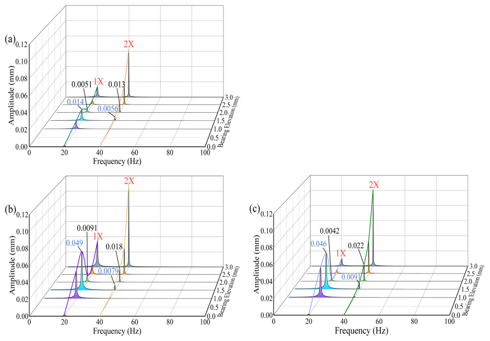
Figure 10Spectrum characteristics at various elevations: (a) bearing 1, (b) bearing 2, and (c) bearing 3.
The analysis of bearing spectra at different elevation increments reveals significant trends in amplitude behavior. At an elevation of 1.5 mm for bearing 3, the 1× amplitudes for bearings 1, 2, and 3 are 0.014, 0.049, and 0.046 mm, respectively. Correspondingly, the corresponding 2× amplitudes are 0.0056, 0.0079, and 0.0091 mm. Notably, the 1× amplitudes exceed the 2× amplitudes by 150 %, 406 %, and 520 %, respectively. When the elevation of bearing 3 is increased by 2 mm, the 1× amplitudes of bearings 1, 2, and 3 are measured at 0.051, 0.0091, and 0.0042 mm, respectively. Correspondingly, the 2× amplitudes are 0.013, 0.018, and 0.022 mm, respectively. At this time, the 1× amplitudes are observed to be 155 %, 423 %, and 98 % lower than the 2× amplitudes for bearings 1, 2, and 3, respectively. The change in bearing 3 elevation leads to the redistribution of the bearing load and the change in stiffness and damping characteristics. Concurrently, the misalignment excitation force also increases. Under the combined action of stiffness and damping and misalignment excitation, when the elevation is 2 mm, the 1× amplitudes of bearings 1, 2, and 3 are reduced by 174.5 %, 995.2 %, and 438.5 %, respectively, in comparison to the amplitudes recorded at an elevation of 1 mm. Conversely, the 2× amplitudes are increased by 132 %, 128 %, and 142 %, respectively.
Changes in the elevation of sliding bearings can affect the vibration response characteristics of the rotor. An analysis of the axis orbit of the rotor operating at 1200 rpm under different elevation conditions revealed the orbit of disk 1 and disk 4, as illustrated in Figs. 11 and 12. It was observed that as the elevation increases, the misalignment excitation on both disks increases, and the axis orbit transitions from a circular shape to a crescent shape, ultimately evolving into a petal shape. The range of displacement within the orbit indicates that the axis orbit of disk 4 is more sensitive to changes in bearing elevation. Notably, when the elevation of bearing 3 is raised to 2 mm, the bearing frequency of the rotor approaches the misalignment excitation frequency, causing resonance, and the axis orbit of both disks becomes petal-shaped, with the core area (S1) occupying the majority. Further increasing the bearing elevation causes the core area (S1) of the petal-shaped orbit, while the petal area (S2) becomes the predominant component.
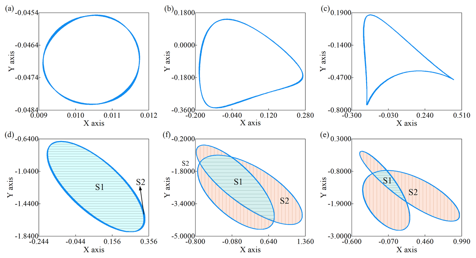
Figure 11Axis orbits of the disk 1 at various elevations: (a) 0 mm, (b) 1 mm, (c) 1.5 mm, (d) 2 mm, (e) 2.5 mm, and (f) 3 mm.
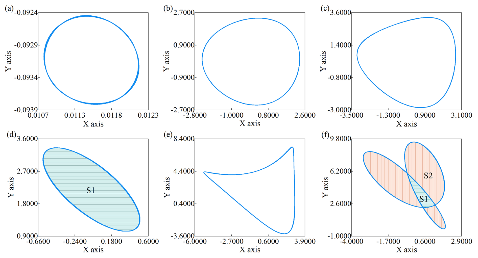
Figure 12Axis orbits of the disk 4 at various elevations: (a) 0 mm, (b) 1 mm, (c) 1.5 mm, (d) 2 mm, (e) 2.5 mm, and (f) 3 mm.
Disk 4 is located in a single-support shaft segment, and its axis orbit differs from that of disk 1, with its orbit change process lagging slightly. When the bearing elevation is increased to 2 mm, resonance occurs in the rotor, and the axis orbit becomes petal-shaped, with the core area (S1) occupying the majority of the orbit. Upon reaching an elevation of 2.5 mm, the rotor ceases to resonate as the bearing frequency deviates from the misalignment excitation frequency. Consequently, the orbit of disk 4 transforms into an inverted crescent shape, accompanied by a reduction in the orbit area. As the bearing elevation further increases, the misalignment excitation acting on disk 4 continues to intensify, and when the elevation reaches 3 mm, the axis orbit becomes an inverted petal shape. With further increases in elevation, the misalignment excitation acting on the rotor gradually intensifies, while the bearing stiffness and damping change correspondingly adjust with the elevation. The displacement amplitude of both disks gradually increases. Ultimately, as the elevation continues to rise, the axis orbits of both disk 1 and disk 4 exhibit increasingly pronounced misalignment characteristics, gradually transitioning into petal-shaped orbits.
The two-span three-support rotor simulation test rig consists of three primary components: a power system, a test system, and a measurement system, as shown in Fig. 13. The rotor system is driven by a motor capable of achieving a maximum speed of 4800 rpm as the driving source, and the motor speed is accurately regulated by a three-phase frequency converter. The test system includes three bearing seats, three sliding bearings, two drive shafts, and a coupling, which together constitute the two-span three-support rotor configuration.
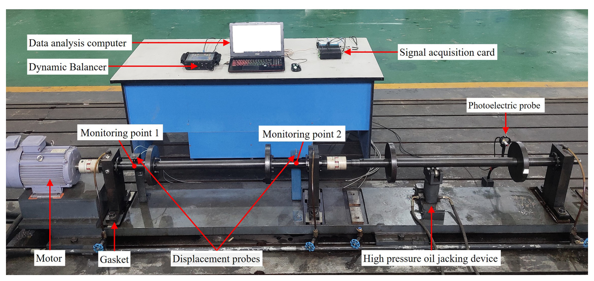
4.1 The structure and working principle of the experimental platform
The testing system of the experimental platform comprises an eddy current displacement signal acquisition device, a speed monitoring device, a misalignment monitoring device, and a hydraulic jacking system. The configuration of the eddy current displacement sensors within the signal acquisition device is shown in Fig. 13. The four eddy current displacement sensors are divided into two groups, arranged at the positions shown in the figure, to monitor the rotor's vibration in both X and Y directions as the elevation changes. The detected voltage variation signals are transmitted to a computer through an acquisition board, and the analysis software facilitates a real-time display of these signals on the computer, thereby enabling the collection of rotor vibration data at different bearing seat elevations. To ensure the accuracy of the rotor's operational speed, a three-phase frequency converter is used to accurately adjust the rotor speed.
The speed monitoring device uses a photoelectric sensor to collect the rotor vibration signals, and a dynamic balancing instrument is used to monitor the rotor's rotational speed. The misalignment monitoring device includes a laser alignment tool, which can accurately monitor the level of rotor misalignment, thereby facilitating the monitoring of rotor alignment conditions. Furthermore, it is equipped with a hydraulic jacking system to assist in elevating the shaft system, thereby simplifying the adjustment of the sliding bearings' elevation.
4.2 Experimental program
To study the effect of changes in sliding bearing elevation on rotor vibration characteristics, it is necessary to minimize the interference caused by initial rotor misalignment. The specific steps are as follows:
- Step 1
-
Adjust the alignment of the coupling on the motor side. Using the motor base as a reference, measure the initial alignment of the motor-side coupling, which should be measured with a laser alignment tool. Following the measurement results, a hydraulic jacking system can be employed to lift the rotor. Subsequently, shims of appropriate thickness should be inserted beneath the corresponding bearing seat and the anchor bolts of the bearing seat. To ensure that the coupling maintains a state of basic alignment post-adjustment, it is essential to remeasure the alignment of the coupling upon the completion of the adjustment process.
- Step 2
-
Adjust the alignment of the coupling within the single-span support section. After completing the elevation adjustment of the motor-side coupling, utilize the motor-side single-span rotor as a reference. Employ the same methodology to align the middle coupling in the two-span three-support rotor system, ensuring that it is in a state of basic alignment.
- Step 3
-
Conduct the vibration test for changes in sliding bearing elevation. After the alignment of the shaft system is completed, the rotor system is first operated, and vibration signals under aligned conditions at different speeds are collected. The sensor sampling frequency is 10 kHz, and data acquisition lasts for approximately 30 s. Subsequently, employ a hydraulic jacking system to lift the single-span rotor and insert a 2 mm thick shim beneath the bearing seat corresponding to bearing 3 to modify the elevation of the sliding bearing. Finally, restart the motor and collect the rotor vibration signals following the adjustment in the elevation of the sliding bearing.
4.3 Comparative validation
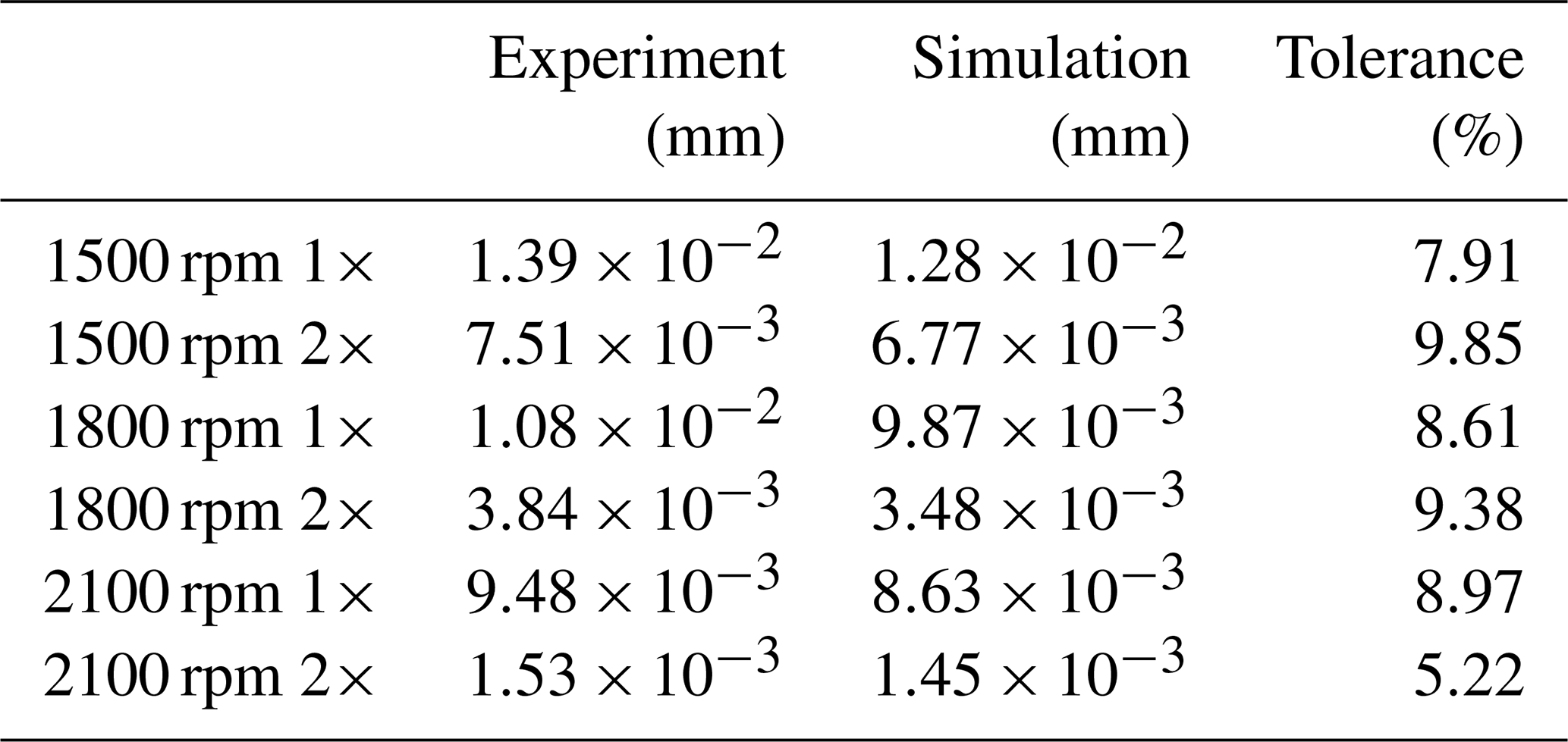
To validate the accuracy of the rotor finite-element model, The accuracy of the rotor model is assessed by comparing the 1× and 2× frequency amplitudes in the experimental and simulation results at monitoring point 2 (as shown in Fig. 13) using data with a duration of 5 s. To minimize the effects of rotor imbalance, the phases of the obtained data are aligned, and the data are processed using the vector subtraction method. The spectral characteristics obtained from experiments, conducted with a bearing elevation of 2 mm, were compared with the spectral characteristics obtained from the simulation, and the results are shown in Fig. 14 and Table 1. Due to the influence of various factors, such as the compression of the sealing ring and parallel misalignment of the coupling during the experiment, there were discrepancies between the experimental and simulation results. The maximum error recorded for the 1× frequency between experimental and simulated values was 8.97 %, while for the 2× frequency, the maximum error was 9.85 %. Both errors remained below 10 %, demonstrating that the rotor model established in this paper has a certain degree of accuracy.
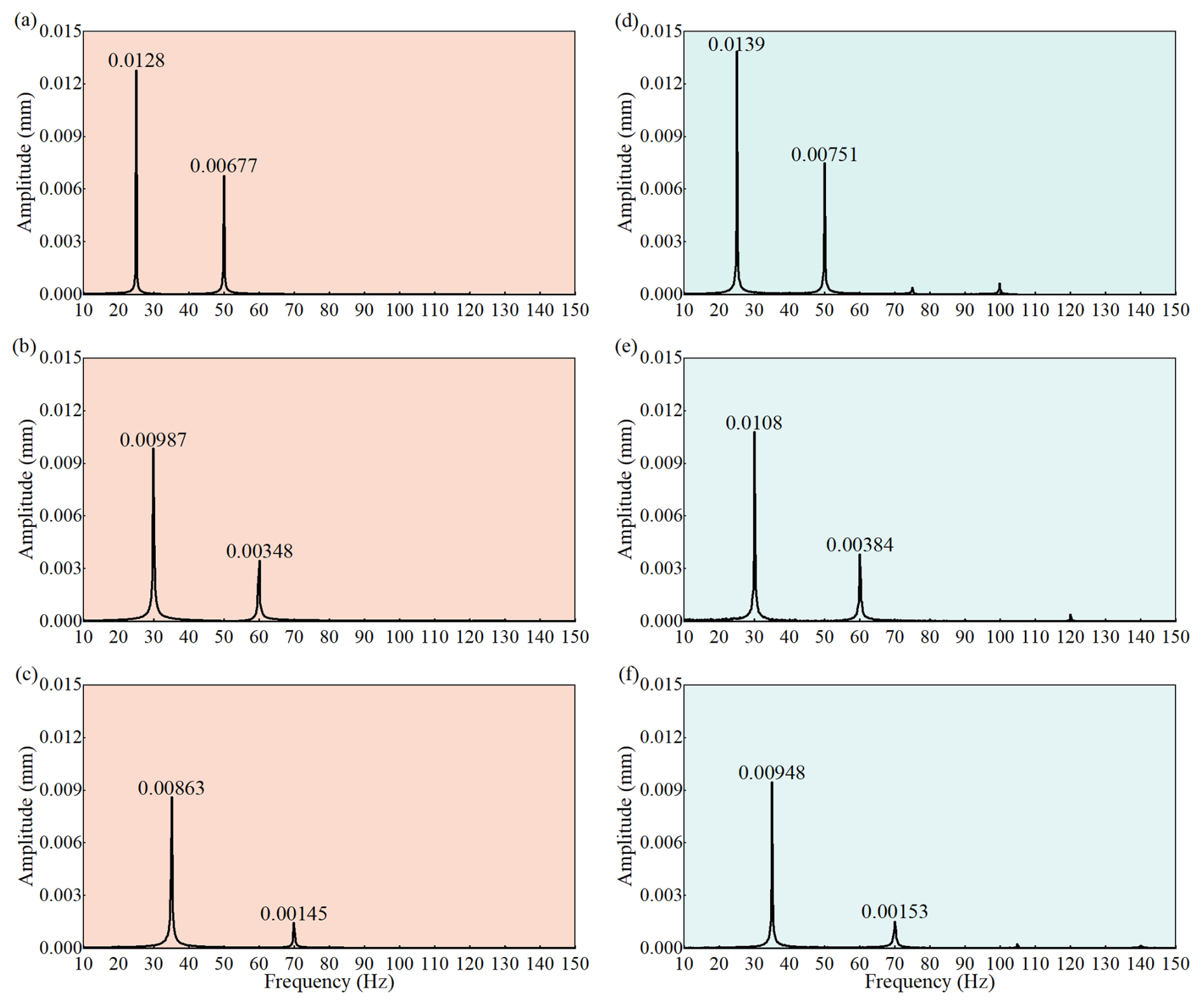
Figure 14Comparison between experimental and simulation spectral results: (a) 1500 rpm simulation, (b) 1800 rpm simulation, (c) 2100 rpm simulation, (d) 1500 rpm experiment, (e) 1800 rpm experiment, and (f) 2100 rpm experiment.
Table 1Comparison between 1× and 2× experimental and simulated peaks.
This study examines the vibration characteristics of a two-span three-support rotor system subjected to varying elevation conditions. The paper commences with an overview of the structure and operational principles of the two-span three-support rotor system. Subsequently, the impact of elevation on the coupling and sliding bearings is analyzed. The dynamic equations for the two-span three-support rotor considering elevation changes are derived, leading to the establishment of a dynamic model of the rotor system. Time domain waveform, spectral characteristics, and axis orbits are analyzed at various rotational speeds and elevation levels. To validate the accuracy of the dynamic model, a test rig for the two-span three-support rotor is designed and built. The conclusions drawn from this study are as follows.
The elevation of sliding bearings is closely linked to both alignment states of the coupling and the dynamic characteristics of the sliding bearings. Variations in elevation may lead to a redistribution of loads on the bearings, which subsequently affects their stiffness and damping coefficients. Additionally, changes in elevation alter the alignment state of the rotor, leading to changes in misalignment excitation. The interplay of these factors ultimately leads to changes in the vibration characteristics of the rotor system.
The elevation of sliding bearings has a direct impact on the time domain and frequency domain characteristics of the two-span three-support rotor. As the elevation of bearing 3 increases, the 1× frequency amplitude at each bearing initially increases, then decreases, and then increases again; in contrast, the 2× frequency amplitude gradually increases with the change in elevation. When the elevation rises from 1.5 to 2 mm, the 1× amplitude at bearing 2 decreases by 438 %, whereas the 2× amplitude increases by 128 %. The change in elevation leads to an increase in misalignment excitation, causing the axis orbit of disk 1 in the two-span rotor section to gradually transform from a circular shape to a crescent shape and eventually to a petal shape.
The results of this study provide valuable insights into the design and vibration control of two-span three-support rotor structures. Specifically, these findings enable a quantitative analysis of the dynamic characteristics of these rotor systems in response to variations in sliding bearing elevation, which is of considerable significance. Future research could further investigate the vibration characteristics of two-span three-support rotor systems in the context of multiple fault couplings.
Data will be made available on request.
ZZ: investigation, software, data curation, formal analysis, and writing (original draft). BGB: writing (review and editing), project administration, resources, and supervision. CL: writing (review and editing), visualization, methodology, and supervision. YG: investigation, validation, and supervision. MMB: supervision.
The contact author has declared that none of the authors has any competing interests.
Publisher's note: Copernicus Publications remains neutral with regard to jurisdictional claims made in the text, published maps, institutional affiliations, or any other geographical representation in this paper. While Copernicus Publications makes every effort to include appropriate place names, the final responsibility lies with the authors.
This work was supported by the National Natural Science Foundation of China (grant nos. 52175091 and 52405103), Hunan Provincial Natural Science Foundation Project (grant nos. 2023JJ30247, 2024JJ6216, and 2023JJ50230), Hunan Province key research and development project (grant no. 2022GK2023), major technical research project of Xiangtan (grant no. ZX-ZD20221002), and Yuelu Mountain Industrial Innovation Center project (grant no. 2024YCII0107).
This research has been supported by the National Natural Science Foundation of China (grant nos. 52175091 and 52405103).
This paper was edited by Hui Ma and reviewed by two anonymous referees.
Al-Hussain, K. M. and Redmond, I.: Dynamic response of two rotors connected by rigid mechanical coupling with parallel misalignment, J. Sound Vib., 249, 483–498, https://doi.org/10.1006/jsvi.2001.3866, 2002.
Avendano, R. D. and Childs, D. W.: One Explanation for Two-Times Running Speed Response Due to Misalignment in Rotors Connected by Flexible Couplings, J. Eng. Gas. Turb. Power, 135, 062501, https://doi.org/10.1115/1.4023232, 2013.
Bin, G., Li, X., Shen, Y., and Wang, W.: Development of whole-machine high speed balance approach for turbomachinery shaft system with N+1 supports, Measurement, 122, 368–379, https://doi.org/10.1016/j.measurement.2018.02.035, 2018.
Bin, G., Li, C., Li, J., and Chen, A.: Erosion-damage-induced vibration response of aero-gas generator rotor system, Mech. Syst. Signal Pr., 195, 110298, https://doi.org/10.1016/j.ymssp.2023.110298, 2023.
Bin, G.-F., Huang, Y., Guo, S.-P., Li, X.-J., and Wang, G.: Investigation of Induced Unbalance Magnitude on Dynamic Characteristics of High-speed Turbocharger with Floating Ring Bearings, Chin. J. Mech. Eng., 31, 88, https://doi.org/10.1186/s10033-018-0287-5, 2018.
Chen, F., Bai, F., Chen, C., Wang, S., and Zhang, H.: Research on double span rotor system driven by motorized spindle with coupling misalignment[J], Adv. Mech. Eng., 11, 1687814018821009, https://doi.org/10.1177/1687814018821009, 2019.
Cui, L., Jin, Z., Huang, J., and Wang, H.: Fault Severity Classification and Size Estimation for Ball Bearings Based on Vibration Mechanism, IEEE Access, 7, 56107–56116, https://doi.org/10.1109/ACCESS.2019.2911323, 2019.
Desouki, M., Sassi, S., Renno, J., and Gowid, S. A.: Dynamic Response of a Rotating Assembly under the Coupled Effects of Misalignment and Imbalance, Shock Vib., 2020, 1–26, https://doi.org/10.1155/2020/8819676, 2020.
El-Mongy, H. H. and Younes, Y. K.: Vibration analysis of a multi-fault transient rotor passing through sub-critical resonances, J. Vib. Control, 24, 2986–3009, https://doi.org/10.1177/1077546317697828, 2018.
Fan, W., Lu, H., Zhang, Y., and Su, X.: Dynamic Characteristics of Gear Coupling and Rotor System in Transmission Process Considering Misalignment and Tooth Contact Analysis, Processes, 8, 1336, https://doi.org/10.3390/pr8111336, 2020.
Hu, S., Han, T., Qi, Y., Zhang, C., Shi, X., and Peng, Z.: Misalignment fault identification of a multi-span rotor system enabled by triboelectric nanogenerators, Nano Energy, 109, 108308, https://doi.org/10.1016/j.nanoen.2023.108308, 2023.
Kumar, P. and Tiwari, R.: Finite element modelling, analysis and identification using novel trial misalignment approach in an unbalanced and misaligned flexible rotor system levitated by active magnetic bearings, Mech. Syst. Signal Pr., 152, 107454, https://doi.org/10.1016/j.ymssp.2020.107454, 2021.
Lal, M.: Modeling and estimation of speed dependent bearing and coupling misalignment faults in a turbine generator system, Mech. Syst. Signal Pr., 151, 107365, https://doi.org/10.1016/j.ymssp.2020.107365, 2021.
Lees, A. W.: Misalignment in rigidly coupled rotors, J. Sound Vib., 305, 261–271, https://doi.org/10.1016/j.jsv.2007.04.008, 2007.
Li, M. and Yu, L.: Analysis of the coupled lateral torsional vibration of a rotor-bearing system with a misaligned gear coupling, J. Sound Vib., 243, 283–300, https://doi.org/10.1006/jsvi.2000.3412, 2001.
Li, Q., Wang, W., Weaver, B., and Shao, X.: Active rotordynamic stability control by use of a combined active magnetic bearing and hole pattern seal component for back-to-back centrifugal compressors, Mech. Mach. Theory, 127, 1–12, https://doi.org/10.1016/j.mechmachtheory.2018.04.018, 2018.
Li, Q., Wang, W., and Chu, F.: Damping ratio identification in rotordynamic system with inverse directional Fourier transform, multiple-tests-multiple-outputs and clustering techniques, Int. J. Mech. Sci., 151, 797–807, https://doi.org/10.1016/j.ijmecsci.2018.12.020, 2019.
Longkai, W., Guangfu, B., Xuejun, L., and Dingqu, L.: Effects of Unbalance Location on Dynamic Characteristics of High-speed Gasoline Engine Turbocharger with Floating Ring Bearings, Chin. J. Mech. Eng., 29, 271–280, https://doi.org/10.3901/CJME.2015.1013.121, 2016.
Lu, K., Jin, Y., Huang, P., Zhang, F., Zhang, H., Fu, C., and Chen, Y.: The applications of POD method in dual rotor-bearing systems with coupling misalignment, Mech. Syst. Signal Pr., 150, 107236, https://doi.org/10.1016/j.ymssp.2020.107236, 2021.
Ma, C., Zhao, D., Sun, W., Liao, W., Xiao, Y., and He, X.: Nonlinear dynamic mechanical response analysis of dual-segment single-span rotor-bearing system under normal condition and misalignment fault, Arch. Appl. Mech., 93, 913–932, https://doi.org/10.1007/s00419-022-02305-z, 2023.
Ma, H., Wang, X., Niu, H., and Wen, B.: Oil-film instability simulation in an overhung rotor system with flexible coupling misalignment, Arch. Appl. Mech., 85, 893–907, https://doi.org/10.1007/s00419-015-0998-3, 2015.
Ma, J., Zhang, H., Lou, S., Chu, F., Shi, Z., Gu, F., and Ball, A. D.: Analytical and experimental investigation of vibration characteristics induced by tribofilm-asperity interactions in hydrodynamic journal bearings, Mech. Syst. Signal Pr., 150, 107227, https://doi.org/10.1016/j.ymssp.2020.107227, 2021.
Mehta, G. D., Shelare, S. D., Pachpor, A. A., Sharma, S., Kumar, R., Bisht, Y. S., Kumar, S., and Abbas, M.: Unravelling the Dynamics of Misalignment-Induced Vibrations in Two Jaw Elastomeric Couplings for Enhanced Industrial Reliability: A Comprehensive Analysis of Dynamics and Diagnostic Approaches, J. Vib. Eng. Technol., 12, 413–426, https://doi.org/10.1007/s42417-024-01423-y, 2024.
Miao, X., Jiang, D., Ai, X., Xu, F., Zhang, D., and Fei, Q.: Dynamic characteristics of rotor system with parallel and angular misaligned involute spline coupling[J], Meccanica, 59, 1061–1085, https://doi.org/10.1007/s11012-024-01842-x, 2024.
Ming, L., Fucai, L., Beibei, J., Huiyu, B., Hongguang, L., and Guang, M.: Multi-fault diagnosis of rotor system based on differential-based empirical mode decomposition, J. Vib. Control, 21, 1821–1837, https://doi.org/10.1177/1077546313502505, 2015.
Nan, G., Wang, H., and Yu, D.: Dynamic Analysis of Three-Rotor System with Hollow Shaft under Clutch Misalignment, Aerospace-Basel, 11, 319, https://doi.org/10.3390/aerospace11040319, 2024.
Patel, T. H. and Darpe, A. K.: Vibration response of misaligned rotors, J. Sound Vib., 325, 609–628, https://doi.org/10.1016/j.jsv.2009.03.024, 2009.
Pennacchi, P.: Nonlinear effects caused by coupling misalignment in rotors equipped with journal bearings, Mech. Mach. Theory, 30, 306–322, https://doi.org/10.1016/j.ymssp.2011.11.020, 2012.
Saavedra, P. N. and Ramírez, D. E.: Vibration analysis of rotors for the identification of shaft misalignment Part 1: Theoretical analysis, P. I. Mech. Eng. C-J. Mec., 218, 971–985, https://doi.org/10.1243/0954406041991297, 2004a.
Saavedra, P. N. and Ramírez, D. E.: Vibration analysis of rotors for the identification of shaft misalignment Part 2: Experimental validation, P. I. Mech. Eng. C-J. Mec., 218, 987–999, https://doi.org/10.1243/0954406041991198, 2004b.
Sawalhi, N., Ganeriwala, S., and Tóth, M.: Parallel misalignment modeling and coupling bending stiffness measurement of a rotor-bearing system, Appl. Acoust., 144, 124–141, https://doi.org/10.1016/j.apacoust.2017.07.022, 2019.
Simm, A., Wang, Q., Huang, S., and Zhao, W.: Laser based measurement for the monitoring of shaft misalignment, Measurement, 87, 104–116, https://doi.org/10.1016/j.Measurement.2016.02.034, 2016.
Sun, R.-B., Yang, Z.-B., Gryllias, K., and Chen, X.-F.: Cyclostationary modeling for local fault diagnosis of planetary gear vibration signals, J. Sound Vib., 471, 115175, https://doi.org/10.1016/j.jsv.2020.115175, 2020.
Tuckmantel, F. W. D. S. and Cavalca, K. L.: Vibration signatures of a rotor-coupling-bearing system under angular misalignment, Mech. Mach. Theory, 133, 559–583, https://doi.org/10.1016/j.mechmachtheory.2018.12.014, 2019.
Wan, Z., Jing, J.-P., Meng, G., Yang, Y., and Bai, H.-Y.: Theoretical and experimental study on the dynamic response of multi-disk rotor system with flexible coupling misalignment, P. I. Mech. Eng. C-J. Mec., 226, 2874–2886, https://doi.org/10.1177/0954406211435582, 2012.
Wang, H. and Gong, J.: Dynamic analysis of coupling misalignment and unbalance coupled faults, J. Low. Freq. Noise. V. A, 38, 363–376, https://doi.org/10.1177/1461348418821582, 2019.
Wang, P., Xu, H., Yang, Y., Ma, H., He, D., and Zhao, X.: Dynamic characteristics of ball bearing-coupling-rotor system with angular misalignment fault, Nonlinear Dynam., 108, 3391–3415, https://doi.org/10.1007/s11071-022-07451-1, 2022a.
Wang, P., Xu, H., Ma, H., Han, H., and Yang, Y.: Effects of three types of bearing misalignments on dynamic characteristics of planetary gear set-rotor system, Mech. Syst. Signal Pr., 169, 108736, https://doi.org/10.1016/j.ymssp.2021.108736, 2022b.
Wang, Z., Zhang, J., Jiang, Z., Mao, Z., Chang, K., and Wang, C.: Quantitative misalignment detection method for diesel engine based on the average of shaft vibration and shaft shape characteristics, Measurement, 181, 109527, https://doi.org/10.1016/j.measurement.2021.109527, 2021.
Xia, Y., Pang, J., Yang, L., Zhao, Q., and Yang, X.: Study on vibration response and orbits of misaligned rigid rotors connected by hexangular flexible coupling, Appl. Acoust., 155, 286–296, https://doi.org/10.1016/j.apacoust.2019.05.022, 2019.
Xiao, L., Xu, Y., Sun, X., Xu, H., and Zhang, L.: Experimental investigation on the effect of misalignment on the wear failure for spline couplings[J], Eng. Fail. Anal., 131, 105755, https://doi.org/10.1016/j.engfailanal.2021.105755, 2022.
Xie, Z., Yang, K., Gao, W., Zhao, B., Du, P., and Zhang, M.: Rotor dynamic behaviors of a novel bearing system with bi-directional tilting effects: Experiment and theory, Mech. Syst. Signal Pr., 220, 111675, https://doi.org/10.1016/j.ymssp.2024.111675, 2024.
Xu, B., Chen, D., Zhang, H., Li, C., and Zhou, J.: Shaft mis-alignment induced vibration of a hydraulic turbine generating system considering parametric uncertainties, J. Sound Vib., 435, 74–90, https://doi.org/10.1016/j.jsv.2018.08.008, 2018.
Zhang, C., Wang, D., Zhu, R., Chen, W., and Yu, C.: Dynamic modeling and analysis of the rotor-bearing-disc coupling system with misalignment, Int. J. Dynam. Control, 11, 2021–2035, https://doi.org/10.1007/s40435-023-01148-y, 2023.
Zhang, H., Huang, L., Li, X., Jiang, L., Yang, D., Zhang, F., and Miao, J.: Spectrum Analysis of a Coaxial Dual-Rotor System with Coupling Misalignment, Shock Vib., 2020, 1–19, https://doi.org/10.1155/2020/5856341, 2020.
Zhao, S., Ren, X., Deng, W., Lu, K., Yang, Y., Li, L., and Fu, C.: A novel transient balancing technology of the rotor system based on multi modal analysis and feature points selection, J. Sound Vib., 510, 116321, https://doi.org/10.1016/j.jsv.2021.116321, 2021.
Zigang, L., Jun, J., and Zhui, T.: Non-linear vibration of an angular-misaligned rotor system with uncertain parameters, J. Vib. Control, 22, 129–144, https://doi.org/10.1177/1077546314525432, 2016.
- Abstract
- Introduction
- Dynamic equation of the rotor system considering elevation
- Analysis of the vibration response of the rotor system
- Experimental validation
- Conclusions
- Data availability
- Author contributions
- Competing interests
- Disclaimer
- Acknowledgements
- Financial support
- Review statement
- References