the Creative Commons Attribution 4.0 License.
the Creative Commons Attribution 4.0 License.
 | 15 Jul 2025
Design and verification of a single-degree-of-freedom driven deformable wheel mechanism
Ce Sha
Yaoyao Huang
Yongli Wang
Bingxiang Wang
Fei Zhou
Guoxing Zhang
Improving the obstacle-crossing ability of special vehicles in complex environments is essential for emergency rescue and security operations. To address this need, a single-degree-of-freedom driven deformable wheel mechanism is proposed, which enables efficient wheel diameter adjustment and a high expansion ratio. First, the degrees of freedom of single-vertex and multi-vertex origami mechanisms are analyzed using the Jacobian matrix method, and then a kinematic model is developed using the improved Denavit–Hartenberg (D–H) method to provide theoretical support for the motion characteristics. Next, a comprehensive performance analysis is conducted, including evaluations of stiffness, expansion ratio, and motion. The mechanism's reliability and adaptability are verified through finite-element and dynamic simulations. In the experimental phase, a prototype of the deformable wheel is fabricated using additive manufacturing technology, and the selected resin material not only ensures excellent processing and shaping properties but also offers a lightweight design and structural stability, effectively enhancing the wheel's expansion performance and overall stiffness. Finally, through expansion ratio testing and performance verification, experimental results demonstrate that the proposed mechanism design features fewer driving components, a high expansion ratio, and strong environmental adaptability. This study provides a possible solution for the design of deformable wheels from the perspective of the feasibility of deployable mechanisms.
- Article
(9159 KB) - Full-text XML
- BibTeX
- EndNote


In military reconnaissance and natural disaster rescue scenarios, such as debris flows and earthquakes, vehicles must navigate complex terrains and challenging road conditions. However, traditional vehicles often struggle to combine rapid mobility, obstacle-surmounting capability, and ride smoothness. Deformable wheels have emerged as a promising technical solution due to their ability to adapt to diverse terrains, significantly enhancing vehicle mobility and obstacle-crossing performance. The folding paper structure, widely used in robotics, offers advantages such as lightweight design, foldability, compactness, and ease of transportation. Deformable wheels inspired by the principles of folding paper achieve high folding ratios, weight reduction, and flexibility. However, their low rigidity and limited load capacity still pose challenges for practical applications. Furthermore, traditional wheeled, crawler, and legged robots all have specific strengths and weaknesses across different terrains, making it difficult for a single mode to meet the diverse demands of complex environments. Deformable wheeled robots have gained significant research attention due to their flexibility and adaptability to various conditions. However, existing designs often suffer from mechanical complexity, excessive weight, and control difficulties. This highlights the urgent need for a more efficient, lightweight, and reliable design solution to overcome these limitations.
Research on deformable wheels focuses on improving adaptability to complex terrains and optimizing obstacle-surmounting performance. Lee et al. (2013a) designed a highly adaptive wheel based on the principles of folding paper to tackle complex terrains. Lee et al. (2013b) developed the OrumBot wheel, employing an umbrella-style paper-folding mechanism to dynamically adjust the diameter for diverse terrains. Berre et al. (2020) introduced a deployable paper-folding wheel that enhances adaptability on uneven surfaces. Kim and Kim (2019) utilized geometric optimization to design a variable-diameter paper-folding wheel, significantly improving obstacle-surmounting performance across multi-terrain environments. Lee et al. (2013b) developed flexible deformable wheels to enhance mobility on soft terrain, while Kimura and Ito (2020) demonstrated the navigation performance of deformable wheels in disaster-response robots, particularly in rubble-strewn environments. Zhang et al. (2024) proposed a single-degree-of-freedom deployable antenna mechanism based on heterogeneous modules, offering innovative insights for lightweight and efficient antenna structures. Wang et al. (2024a) designed a deformable legged robot capable of dynamically switching between legged modes, improving its environmental adaptability. In another study, Wang et al. (2019) developed a membrane-folding wheel with a high load capacity exceeding 10 kN, providing a robust foundation for vehicles operating in complex terrains. Additionally, Zhang and Ng (2020) combined additive manufacturing with paper-folding technology to design high-strength deformable wheels, offering a reliable solution for applications in challenging environments.
Deployable mechanisms have become a significant research focus in deformation mechanisms due to their lightweight nature, adaptability, and ability to be reconfigured for various applications. Endo et al. (2014) designed a deployable wheel embedded within fabric, demonstrating its potential for lightweight and flexible applications. Guo et al. (2023) proposed a deployable mechanism based on a novel pyramid module, exploring its configuration integration and lightweight network design to enhance structural efficiency and adaptability. Felton et al. (2014) reviewed the application of deployable structures in complex mechanical systems, highlighting the importance of dynamic deformation optimization. Masana and Daqaq (2023) and Liu and Chen (2021) conducted kinematic analyses of the folding modes in deployable mechanisms, providing valuable theoretical support for geometric design optimization. Yin and Feng (2019) developed a biomimetic deployable wheel and validated its adaptability in multi-terrain robotic applications. Miura and Nakamura (2015) investigated the lightweight characteristics of deployable structures in spacecraft deployment designs, showcasing their advantages in dynamic deformation scenarios. Guo et al. (2022) designed a truss-deployable antenna mechanism based on the 3RR-3URU tetrahedron element, analyzing its mechanical properties and structural optimization to inform lightweight aerospace antenna development. Wang et al. (2024b) proposed a reconfigurable deployable structure with multiple stabilities, highlighting its potential applications in robotics and meta-materials. Chai et al. (2024) studied programmable multi-stable deployable structures, achieving precise control of morphological transformations. Li et al. (2020) reviewed advancements in 4D printing technology using shape memory polymers and explored its application prospects in deployable structures. Kim et al. (2020) developed a complex deformation-mode-deployable driver by integrating 3D printing technology with UV-curing elastomers, offering an innovative technical solution for applications in soft robotics.
Deformable mechanisms have been widely studied due to their ability to adapt to various environmental conditions and applications. Fang et al. (2017) demonstrated the potential of geometric complexity in paper-folding structures. Shao et al. (2020) investigated multi–walled carbon nanotubes (MWNT)–poly dimethylsiloxane (PDMS) composite materials, achieving self-enhancement of electrical conductivity during stretching by optimization of interface interactions and offering a novel material solution for flexible electronic devices. Rus and Tolley (2015) reviewed the critical role of precise control and dynamic deformation design in soft robotics. Xue et al. (2025) advanced technologies for lightweight structures, optimizing the overall performance of paper-folding systems. Miyashita and Rus (2017) highlighted the multifunctional design potential of medical paper-folding devices. Overvelde et al. (2017) enhanced the mechanical performance of paper-folding structures, improving both strength and versatility. Wang et al. (2019) reviewed 4D printing technologies for intelligent polymers, emphasizing their application in complex deformation structures and reconfigurable systems. The combination of paper-folding structures has shown immense potential in developing multifunctional deformable systems. Felton et al. (2014) proposed such a system, offering guidance for future design optimization. Kong and Cheng (2020) explored the application of biomimetic paper-folding wheels in multi-terrain robotics, verifying their reliability in complex environments. Berre et al. (2020) designed a lightweight paper-folding heuristic wheel and experimentally validated its adaptability in complex environments and diverse application scenarios.
Current research on deformable wheels focuses on support and deformation mechanisms but struggles to achieve both high efficiency and deformability due to structural limitations. Similarly, while paper-folding mechanisms emphasize motion principles and degree-of-freedom analysis, their application to deformable wheels remains rare. Existing deformable wheels often face challenges such as low load capacity and complex driving mechanisms. This paper introduces a novel deformable wheel design based on paper-folding principles, utilizing resin materials to enhance lightweight properties, structural strength, and deformation stability. High-precision machining of complex geometries further improves the load capacity. A degree-of-freedom model is developed using the Jacobian matrix method, and a kinematic model is established with an improved Denavit–Hartenberg (D–H) method. Key parameters such as load capacity, folding rate, and kinematics are analyzed. The design's feasibility and performance are validated through a resin-based prototype and folding experiments, showcasing its potential for efficient and adaptable deformable wheels.
Rigid paper-folding mechanisms require consideration of foldability and degrees of freedom. These mechanisms treat creases as rotational joints and rigid panels as linkages, with the degrees of freedom determined by independent motion parameters. Based on folding requirements for wheels, square paper is classified into single-point and multi-point folding configurations. Position constraint equations are established for characteristic points, and the Jacobian matrix is derived to analyze and calculate the mechanism's degrees of freedom. The analysis of the principle of the single-vertex origami mechanism is the basis for the design of the multi-vertex origami mechanism.
2.1 Free degree analysis of the single-vertex paper-folding mechanism
2.1.1 Folding-mark division of the single-vertex paper-folding mechanism
To analyze the degrees of freedom of the paper-folding mechanism, a Cartesian rectangular coordinate system must be established, and the rigid body constraints of each component are calculated based on the limits of the designed rotational joints. The surfaces of the paper-folding mechanism are generally composed of triangles or quadrilaterals, and the arrangement of creases and unit combinations significantly influences its overall degrees of freedom. It is essential to define the rigid body constraints and degrees of freedom for each component according to the specific design requirements. First, based on the requirements for the expansion and folding states of the deformable wheel, the crease pattern of the square paper is divided to form creases and crease nodes, as illustrated in Fig. 1. A Cartesian coordinate system is then established at one endpoint of the square paper, with point O designated as the origin. Node 1 marks the origin, and nodes 2 to 9 are labeled counterclockwise. The direction from node 1 to node 2 is defined as the positive x axis and the direction from node 1 to node 7 as the positive y axis. The z axis is determined using the right-hand rule, as shown in Fig. 1. The red line represents a concave crease, and the blue line represents a convex crease.
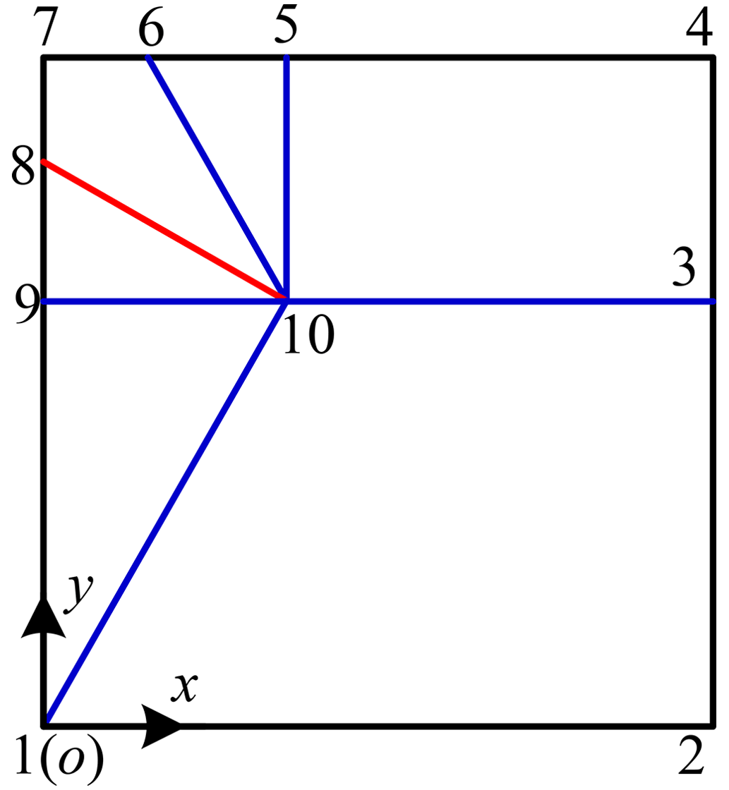
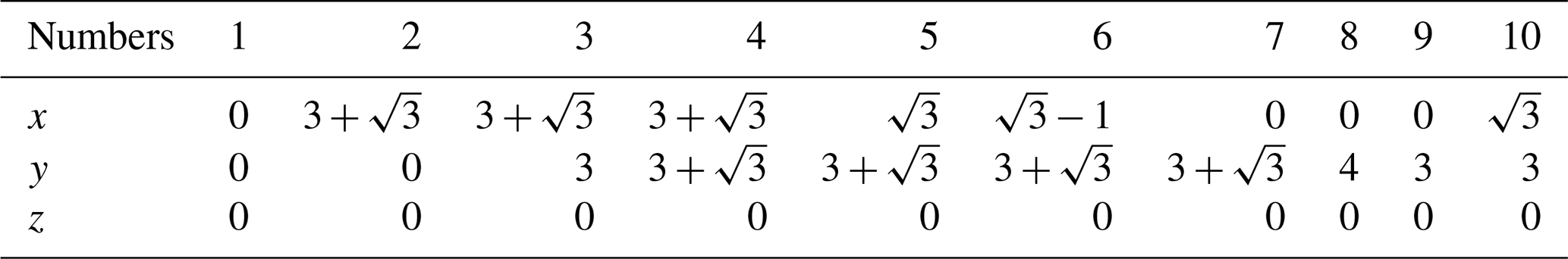
Taking o-xyz as the coordinate, the relative position of each node can be obtained. Assuming that the square paper in Fig. 1 has the same length on each side and the length of l89 is 1, . The coordinate values of each node in the coordinate system o-xyz are shown in Table 1.
Table 1Coordinate values of each node in the single-vertex paper-folding mechanism.
2.1.2 Degree-of-freedom analysis of a single-vertex origami mechanism
Based on the positional relationships of the single-vertex origami mechanism, the coordinates of each node in the o-xyz coordinate system are determined, enabling the calculation of the motion constraint conditions for the single-vertex folding mechanism. As shown in Fig. 1, the creases allow a square sheet of paper to be regarded as a foldable mechanism. Analysis reveals that this folding mechanism consists primarily of six sets of rigid plate elements, of which nodes 1-9-10, 5-6-10, and 8-9-10 form triangular elements and nodes 1-2-3-10, 3-4-5-10, and 6-7-8-10 form quadrilateral elements. Based on the creases in Fig. 1 and the node coordinates of the single-vertex origami mechanism listed in Table 1, the constraint equations for the triangular and quadrilateral rigid plate elements can be derived, as shown in Eqs. (1) and (2):
where a is a constant.
Furthermore, the distances between different nodes of the single-vertex origami mechanism are given as shown in Eq. (3).
By analyzing the boundary constraints of the triangular and quadrilateral rigid plates, the shape constraint relationships for these rigid plates can be determined. The boundary constraint conditions for the triangular rigid plates are shown in Eq. (4), while those for the quadrilateral rigid plates are described in Eqs. (4) and (5):
where b is a constant.
Considering the connection relationship between triangular and quadrilateral rigid plates, when there are overlapping points between two rigid plates, the connection between the two plates can be regarded as a spherical joint. This satisfies the constraint conditions without the need to add additional constraint equations.
The Jacobian matrix of the single-vertex origami mechanism is derived based on the constraint conditions in Eqs. (1)–(5). The Jacobian matrix of the single-vertex origami mechanism is expressed in Eq. (6).
In the equation, m represents the number of constraint equations, and n represents the number of unknown variables.
Substituting the 39 constraint equations and the 30 node coordinate variables into Eq. (6) results in a 39 × 30 Jacobian matrix J. Using the matrix analysis software MATLAB, the null space of the Jacobian matrix J is calculated to be 3. Therefore, the degree of freedom of the single-vertex six-crease origami mechanism shown in Fig. 1 is determined to be 3.
2.2 Degree-of-freedom analysis for the multi-vertex origami mechanism
2.2.1 Crease division of the multi-vertex origami mechanism
Based on the design and analysis of the single-vertex origami mechanism, the multi-vertex origami mechanism is analyzed with consideration of a circular wheel structure. The single-vertex origami mechanism shown in Fig. 1 requires one concave crease and five convex creases to achieve folding. For the multi-vertex origami mechanism shown in Fig. 2, adjacent creases need to be shared. According to the outline of the expandable wheel, the shape of the creases at the vertices changes. For example, the shape of crease 8-9-10 shown in Fig. 1 is adjusted to the shape of crease 12-13 shown in Fig. 2. Adjust the shape of crease 5-7-8-10 to the shape of crease 22-10-12-23. A 12-sided deformable sheet is divided to form the multi-vertex origami structure with a central regular hexagon, as shown in Fig. 2. As illustrated in Fig. 2, the origami structure is divided into 19 rigid plate elements by 24 creases. The structure has six vertices, with five creases intersecting at each vertex. Of the 24 creases, 6 are concave creases marked with red lines, while the remaining 18 are convex creases marked with blue lines. Of the 19 rigid plate elements, 6 are quadrilateral rigid plates, 12 are triangular rigid plates, and the center consists of 1 regular hexagonal rigid plate.
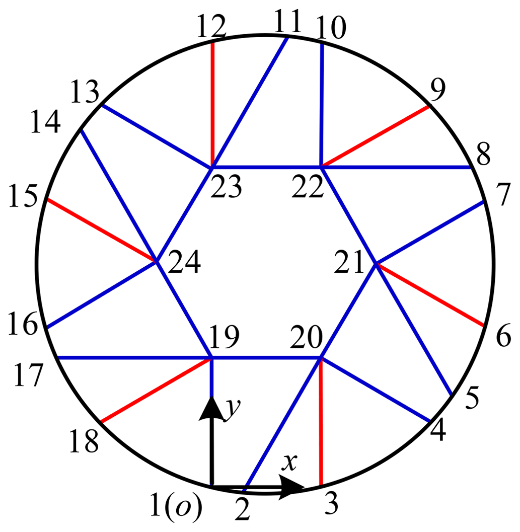
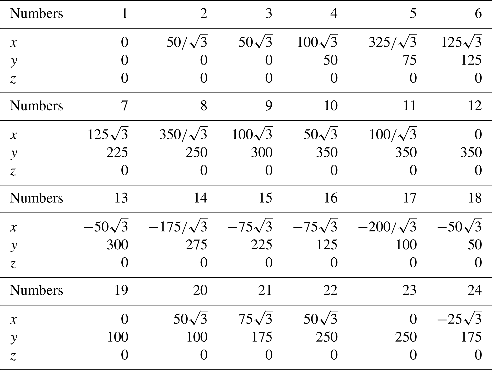
Following an outside-to-inside sequence, the nodes of the structure shown in Fig. 2 are numbered counterclockwise from 1 to 24. A Cartesian coordinate system is established, where the origin o is located at node 1, the positive x axis aligns with the direction of nodes 1–3, and the positive y axis aligns with the direction of nodes 1–19. The z axis direction is determined by the right-hand rule. Through the crease division, the multi-vertex origami mechanism includes right-angled trapezoids, equilateral triangles, right-angled triangles with a 30° acute angle, and a regular hexagon. Assuming the side length of the equilateral triangle is 100 mm, the specific positions of each node in the coordinate system are listed in Table 2.
Table 2Coordinate values of each node of the multi-vertex origami mechanism.
2.2.2 Degree-of-freedom analysis of the multi-vertex origami mechanism
Based on the positions of each node in the coordinate system, the folding constraints and constraint equations of the multi-vertex origami mechanism can be derived. From the crease analysis, it is known that the mechanism consists of 19 rigid panels, including 12 triangular rigid panels and 6 quadrilateral rigid panels. The 12 triangular rigid panels are 2-3-20, 3-4-20, 2-6-21, 6-7-21, 8-9-22, 9-10-22, 11-12-23, 12-13-23, 14-15-24, 15-16-24, 17-18-19, and 1-18-19. The six quadrilateral rigid panels are 1-2-20-19, 4-5-21-20, 7-8-22-21, 10-11-23-22, 13-14-24-23, and 16-17-19-24. It is evident that the constraint equations for the triangular rigid panels are shown in Eq. (7), while those for the quadrilateral rigid panels are shown in Eq. (8).
c is a constant.
Similarly, the constraint conditions of the quadrilateral rigid plates can be obtained by considering the overlap of six sides of regular hexagonal rigid plates and six quadrilateral rigid plates; i.e., the adjacent rigid plates can be regarded as spherical joints, and the adjacent nodes meet the constraint conditions. So far, the rigid plate conditions, boundary constraints, and structural conditions required by the multi-point paper-folding structure as well as the constraints of the entire structure have been clear. By collating the above constraints, the corresponding constraint equations can be obtained, which are generally written as Eq. (9):
where j is . m is the number of constraint equations. n refers to the number of paper-folding mechanism joints.
Through the research on the motion of the paper-folding mechanism, it can be seen that its constraint condition includes a function related to time, and it can be represented by a Jacobian matrix that can be represented by Eq. (10).
By applying the constraint equation, we can obtain a Jacobian matrix of the multi-vertex paper-folding mechanism and input it into MATLAB for auxiliary calculation, so that the zero-space dimension is 6; i.e., the freedom of the multi-vertex paper-folding mechanism shown in Fig. 2 is 6.
In order to describe the kinematic model of the paper-folding mechanism, it is necessary to express the relationship between the folding unit, crease, and node before and after folding of the paper-folding mechanism. Taking the single-vertex paper-folding mechanism as an example, mark the fixed folding unit as P1 and the remaining folding units as P2 to P6 counterclockwise. Then mark the folds of the folding unit Pi and the folding unit Pi−1 as ei and complete the marking of the folding unit and the folds of the single-vertex six-fold paper-folding mechanism, as shown in Fig. 3.
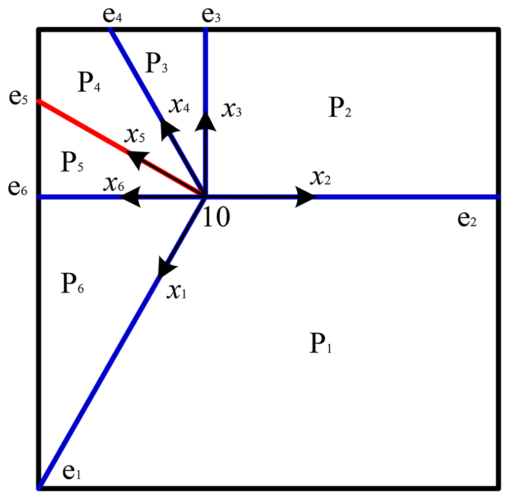
Taking the vertex of the paper-folding mechanism as the center, i.e., the direction along the ei crease as the positive direction of the axis, the xi axis is vertical to the paper surface upward, and zi is determined according to the right-hand rule to establish the coordinate system of each crease. It can be seen from the characteristics of the paper-folding mechanism that the included angle between the x axes of two adjacent groups of plates remains unchanged during the folding movement. The relationship between the included angle of the z axes of two adjacent groups of plates and the included angle on the back of the plate is shown in Eq. (11).
The vector P in the coordinate system oixiyizi can be converted into the vector Pi in the coordinate system by Eq. (12). As the paper-folding mechanism is a single-vertex mechanism and the origin of each coordinate system is the same, the formula and Eq. (12) can also be written as Eq. (13).
represents the rotation change in the i+1 coordinate system relative to the i coordinate system. refers to the translation change in the i+1 coordinate system relative to the i coordinate system.
Coordinate system oixiyizi obtains the temporary coordinate system by rotating counterclockwise around axis zi and then rotating counterclockwise around axis to obtain coordinate system , so its coordinate system change is shown in Eq. (14).
The multi-vertex origami mechanism in Fig. 4 consists of 19 panels and 24 creases, forming a complex geometric structure with rotational symmetry. Therefore, the labeling is carried out by taking the central panel as the reference panel P1, and the panels are sequentially labeled counterclockwise from P2 to P19. At the same time, the intersections of the creases, which are the vertices of the central regular hexagon, are labeled sequentially from A to F. For crease labeling, a counterclockwise direction is used, with the vertex as the starting point. The crease between panel Pi and panel Pj is labeled e j. For example, starting from vertex A, the crease between panel P19 and panel P2 is labeled e2. The labeling after this process is shown in Fig. 4.
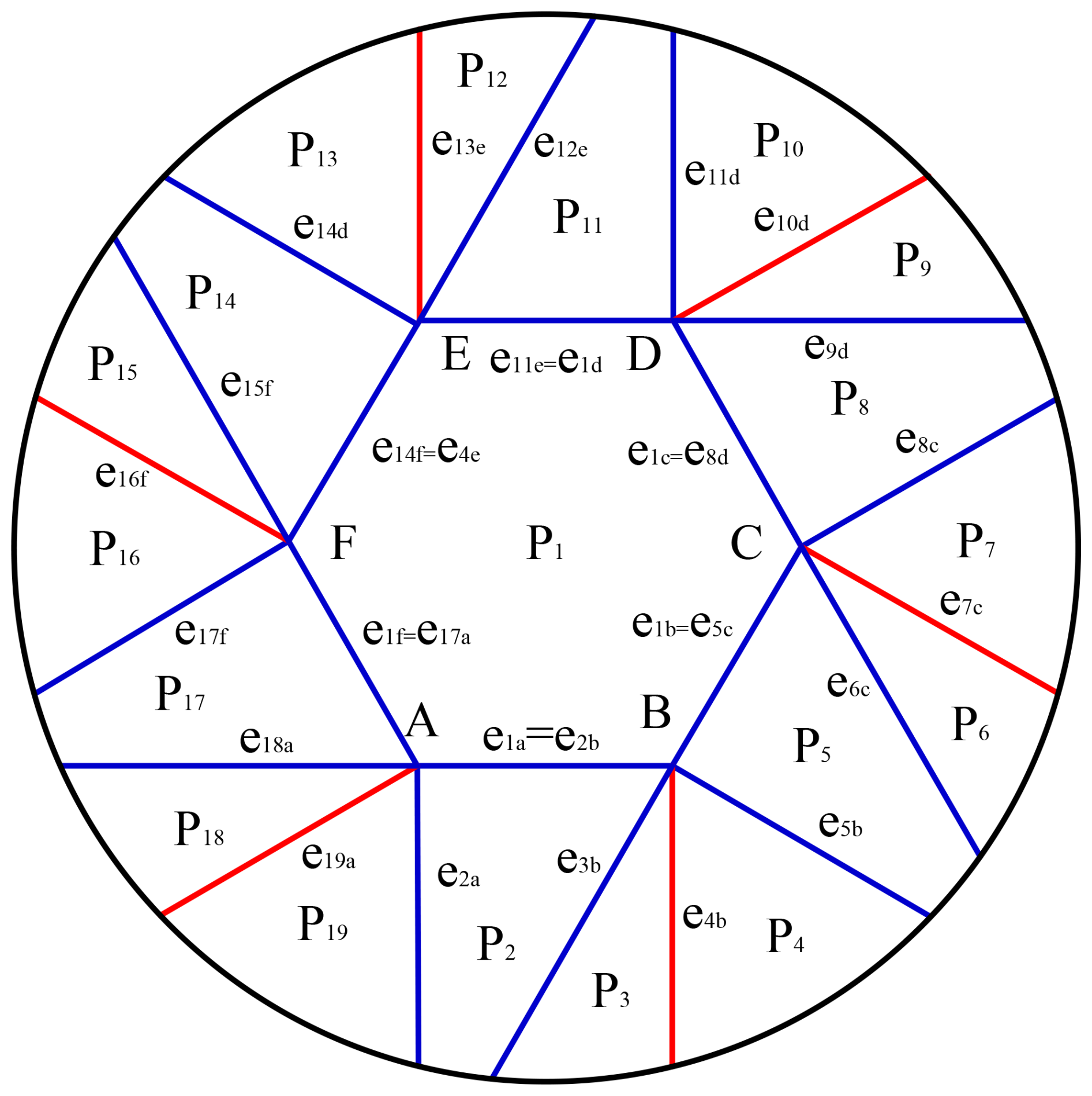
Here, a vertex is added to the subscript to discern and avoid repeated annotation when marking the crease. For example, the modified crease annotation that intersected at Point A is e1a, e2a, e17a, e18a, and e19a. At the same time, we also found that there are multiple marked creases. For example, e1a and e2b are the same crease, e1b and e5c are the same crease, etc., to complete the equivalent of the same fold of the six vertices. Through this marking mode, we can have a better understanding of the structure of the paper-folding mechanism for subsequent design and manufacturing.
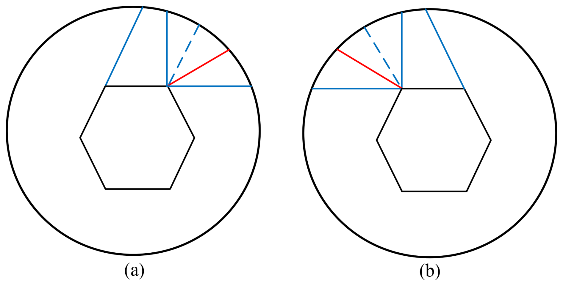
Figure 5Segmentations of basic units of the origami mechanism. (a) Front view. (b) Back view.
4.1 Configuration optimization of the deformable wheel mechanism
The deformable wheel is composed of multiple groups in a paper-folding mechanism's basic unit circumferential array, so the shape and quantity of the paper-folding mechanism's basic unit will be set reasonably. Considering the good symmetry and separable characteristics of a hexagon, the wheel section is segmented based on a hexagon. At the same time, considering the overall complexity of the wheel and the support stiffness, the basic unit number of the paper-folding mechanism is set to six groups. Considering the internal and external folding of the basic unit of the paper-folding mechanism and the complexity of the mechanism, the isosceles trapezoidal basic unit is divided into four parts, including a right-angled trapezoid and three groups of right-angled triangles. The basic unit division mode of the paper-folding mechanism is shown in Fig. 5. Here, Fig. 5a is the front view continuing from Fig. 4 and Fig. 5b is the back view observed from the back of the paper. The perspective of Fig. 5b is consistent with that of the virtual prototype model of the deformable wheel at the back.
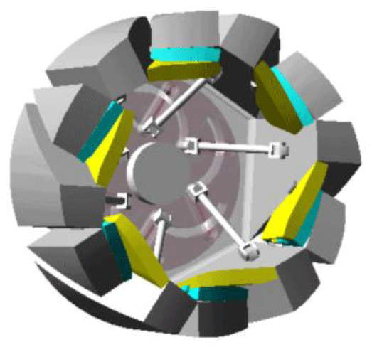
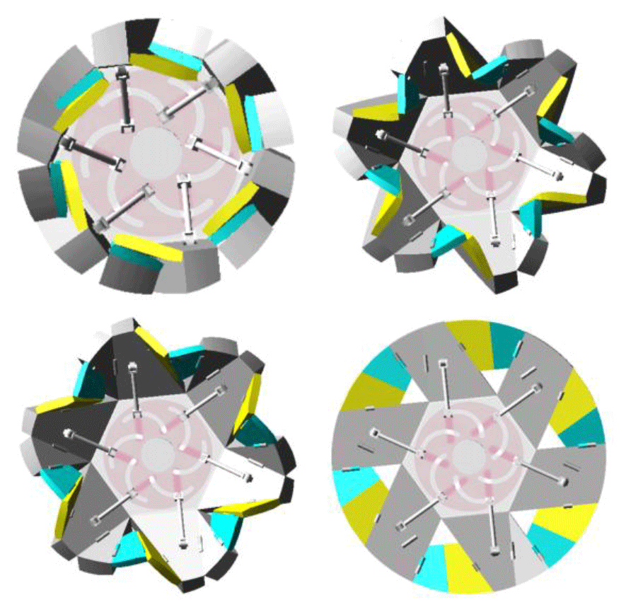
Further, considering the expansion and retraction states of the basic unit of the paper-folding mechanism and the interference caused by the plate thickness, the folding of the basic unit is realized by adjusting the hinge position and the plate shape, and the complete foldable wheel is obtained by creating a circumferential array of the basic unit of the paper-folding mechanism, as shown in Fig. 6. Figure 6a shows the retracted state of the deformable wheel, Fig. 6b shows the semi-retracted state of the deformable wheel, and Fig. 6c shows the unfolded state of the deformable wheel.
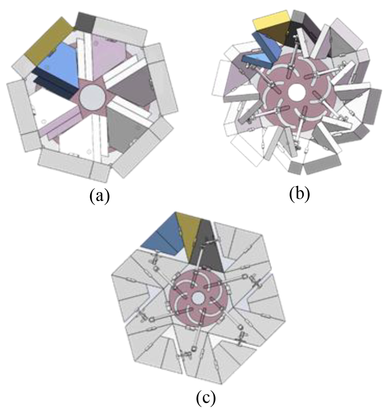
Figure 6Deformable wheels before optimization. (a) Folding state. (b) Middle folding state. (c) Unfolded state.
As shown in Fig. 6, the outer contour of the deformable wheel before and after folding is not circular, which results in the wheel being unable to roll effectively and smoothly, so further optimization of the deformable wheel is required. First, the shape adjustment method is adopted for the two plates in large-area contact, and the expansion and folding of the thick plate model are realized while maintaining the same motion characteristics as the thin plate, as shown in Fig. 7. Then, the contouring was modified to a nearly circular shape for easier scrolling, as shown in Fig. 8.
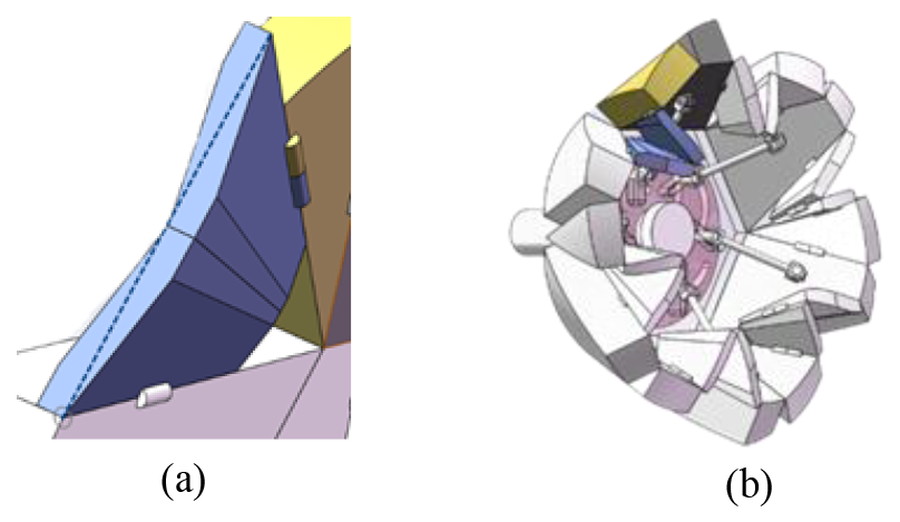
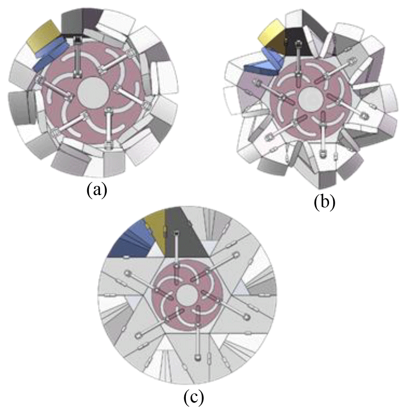
Figure 8Deformable wheels after optimization. (a) Folding state. (b) Middle folding state. (c) Unfolded state.
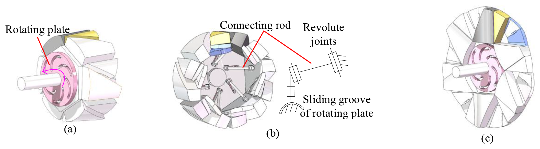
Figure 9Drive connection of the deformed wheel mechanism. (a) Rotating plate. (b) Connecting rod. (c) Unfolded state.
The driving method of the deformed wheel mechanism relies on the clockwise and counterclockwise rotation of the rotating disc behind the wheel, which drives the foldable part of the wheel to collapse and unfold through the rotating connecting rod. The driving and unfolding structure is shown in Fig. 9.
The deformable wheel comprises six sets of connecting rods. As detailed in Fig. 9b, each rod consists of three revolute joints, with one end attached to the driving panel of the deformable wheel and the other end sliding along the groove of the rotating plate. When the rotating plate is actuated, the motion is transmitted through the rods to drive the active panels of the deformable wheel. This mechanism enables single-degree-of-freedom actuation via the rotating plate to achieve synchronized folding or deployment of the entire wheel structure.
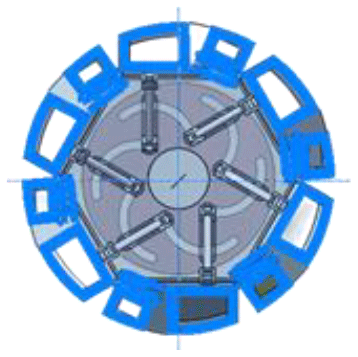
In order to reduce the moment of inertia of the deformable wheel during driving and deformation, it is necessary to reduce the weight of the deformable wheel at the structural design stage. The method for extracting the shells of plates with large thicknesses of the deformable wheel is to remove the material in the center of these plates. The profile of the deformable wheel after extraction is shown in Fig. 10.
For wheels, the larger the diameter in the spreading state, the higher the stability and driving speed of the vehicle. In the folding state, the smaller the wheel diameter, the smaller the space occupied by the vehicle and the easier it is to carry. In the process of deformation, with the change in wheel diameter, the axial position also changes up and down, and the axial position has a great impact on the performance and driving stability of the wheel.
4.2 Static analysis of the deformable wheel mechanism
The bearing capacity is the basic factor in measuring the wheel performance. Therefore, it is necessary to analyze the bearing capacity of a deformable wheel before and after deformation. The simple trolley model assembled with four groups of deformable wheels is established after the 3D model of deformable wheels is drawn, as shown in Fig. 11.
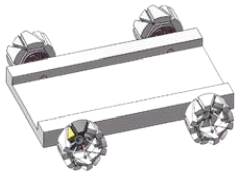
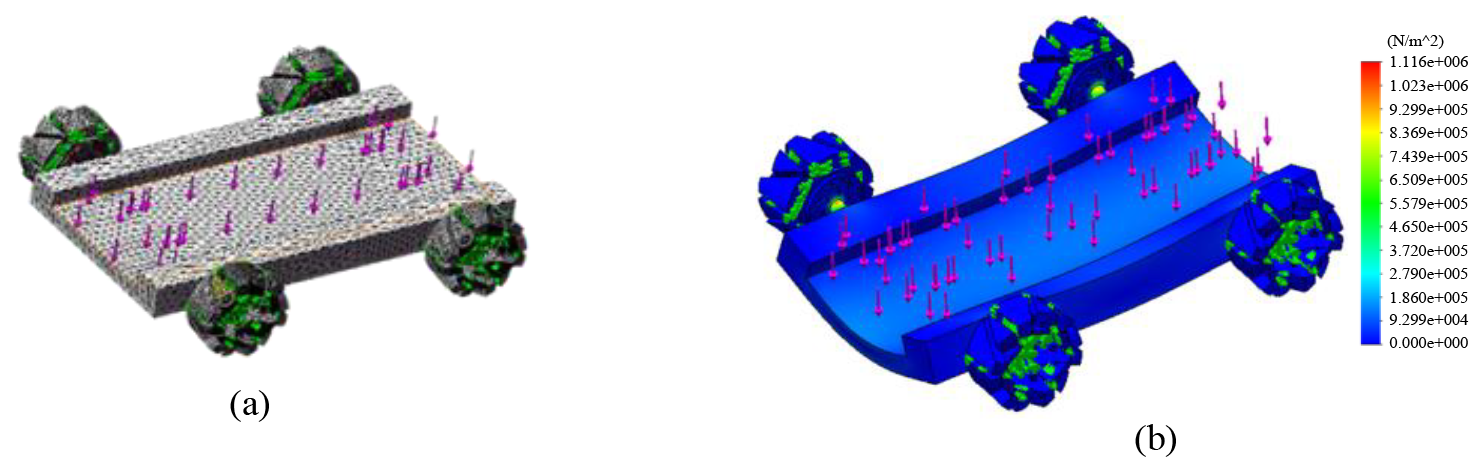
Figure 12Finite-element model of deformable wheel vehicles. (a) Grid division. (b) Static analysis.
In ANSYS/Workbench the material properties are set for resin and nylon, respectively. The elastic modulus of the resin material is 2.8 GPa, the tensile strength is 65 MPa, the elastic modulus of the nylon material is 3.3 GPa, and the tensile strength is 90 MPa. The boundary conditions are set for the finite-element model after the meshing is completed. The complete vehicle finite-element model of deformable wheels is shown in Fig. 12a. When the vehicle is stationary, a force of 400 N is applied to the vehicle floor, and the finite-element analysis results are shown in Fig. 12b. From Fig. 12b, it can be seen that the highest stress of the vehicle is located at the joint between the rotating shaft and the plate, and the lowest stress of the vehicle is on the plate at the top of the deformable wheel. The stress and deformation of the vehicle model are small, meeting the bearing performance requirements.
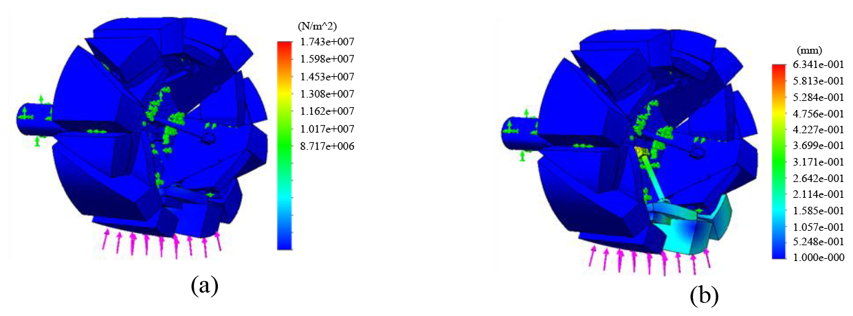
Figure 13Finite-element analysis of deformable wheels in a folding state. (a) Stress cloud map. (b) Deformation cloud map.
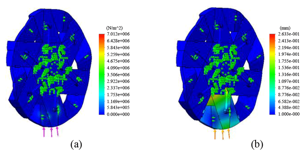
Figure 14Finite-element analysis of deformable wheels in a folding state. (a) Stress cloud map. (b) Deformation cloud map.
In order to observe the stress under the wheel load more intuitively, the finite-element analysis of the folding state and unfolding state of the wheels on both sides is carried out. The simulation analysis results are shown in Figs. 13 and 14.
It can be seen from Fig. 14 that the maximum deformation of a single deformable wheel is 0.634 mm in the folded state and 0.263 mm in the unfolded state. The large deformation of the deformable wheel in the folding state is mainly caused by no support outside the folded wheel. In general, the deformation range of the deformable wheel meets the strength requirements, and the collapsible state and unfolded state of the deformable wheel will not produce serious structural damage.
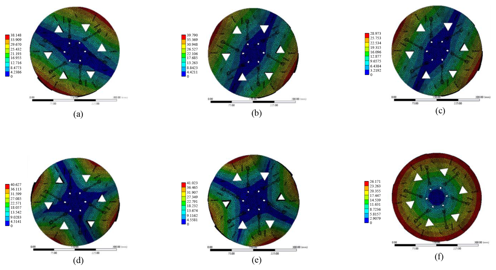
Figure 15The unfolded vibration mode of the deformable wheel mechanism. (a) First-order mode. (b) Second-order mode. (c) Third-order mode. (d) Fourth-order mode. (e) Fifth-order mode. (f) Sixth-order mode.

Figure 16Folding state vibration mode of the deformable wheel mechanism. (a) First-order mode. (b) Second-order mode. (c) Third-order mode. (d) Fourth-order mode. (e) Fifth-order mode. (f) Sixth-order mode.
4.3 Analysis of the vibration characteristics of the deformable wheel mechanism
Vibration analysis suppresses the vibration response of the system through frequency response signal analysis and modal analysis. The vibration characteristics of the deformable wheel mechanism are studied by the ANSYS/Workbench vibration analysis module. Considering the actual working mode of the deformable wheel mechanism, the vibration characteristics of the deformable wheel mechanism in the spreading state and folding state are analyzed. The base end of the deformable wheel mechanism is provided with a fixed constraint, and the load is applied at the axle center of the deformable wheel. The cloud images of vibration modes of the deformable wheel mechanism in the deployed and folded states are shown in Figs. 15 and 16.
It can be seen from the vibration diagrams in Figs. 15 and 16 that the end of the folded edge of the deformable wheel mechanism deforms greatly, which produces high alternating stresses easily, resulting in fatigue crack and fracture. The end of the folded edge of the deformable wheel mechanism is a relatively weak link, and the overall rigidity can be improved by increasing the unbounded branch chain.
Table 3Natural frequency and vibration mode of the deformable wheel mechanism.
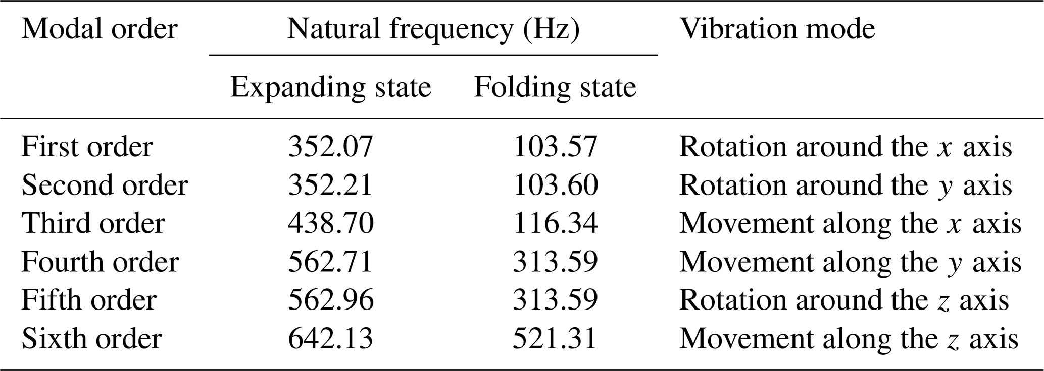
It can be seen from Table 3 that the natural frequency of the first six stages of the deformable wheel mechanism in the deployed state is 352.07–642.13 Hz, and the natural frequency of the first six stages in the folded state is 103.57–521.31 Hz. The natural frequency of the deformable wheel mechanism in the folded state is small, and a given deformable wheel excitation needs to be higher than the lowest natural frequency in the folded state to avoid resonance.
4.4 Dynamic analysis of the deformable wheel mechanism
To verify the effectiveness of the deformable wheel mechanism in the wheel deformation process, a 3D model is imported into the ADAMS software for kinematic and dynamic analysis. The kinematic pair and constraint conditions are added to the ADAMS simulation model, the given driving shaft speed is 15 ° s−1, the simulation time is set to 1.5 s, and the simulation steps are set to 25. The dynamic simulation model of the deformable wheel is shown in Fig. 17.
Based on the dynamic simulation analysis of ADAMS, the process from folding to unfolding of the deformable wheel mechanism is obtained, as shown in Fig. 18.
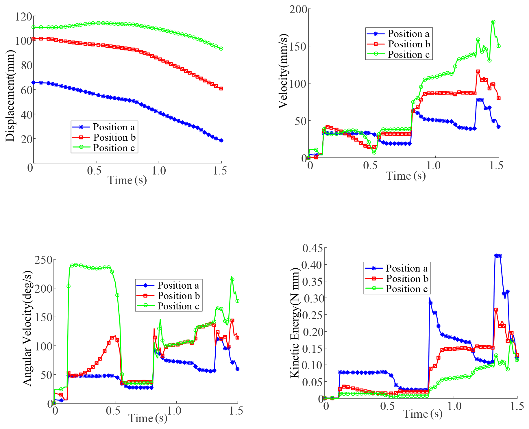
The linear velocity, angular velocity, and actuation torque of the deformable wheel mechanism during the transition from the folded state to the deployed state were analyzed using ADAMS dynamic simulations. The results are presented in Fig. 19.
The analysis results show that the motion curve of the deformable wheel mechanism is smooth without interference, and the deformable wheel mechanism can realize folding and unfolding motions. At the same time, the joint driving torque parameters obtained by simulation provide a reference for the drive motor selection of the deformable wheel mechanism prototype.
The development of the principle prototype is helpful for checking the feasibility of the design scheme at the design stage and improving the product development efficiency. The principle prototype of the deformable wheel mechanism is developed based on 3D printing technology. The parts of the deformable wheel are shown in Fig. 20.
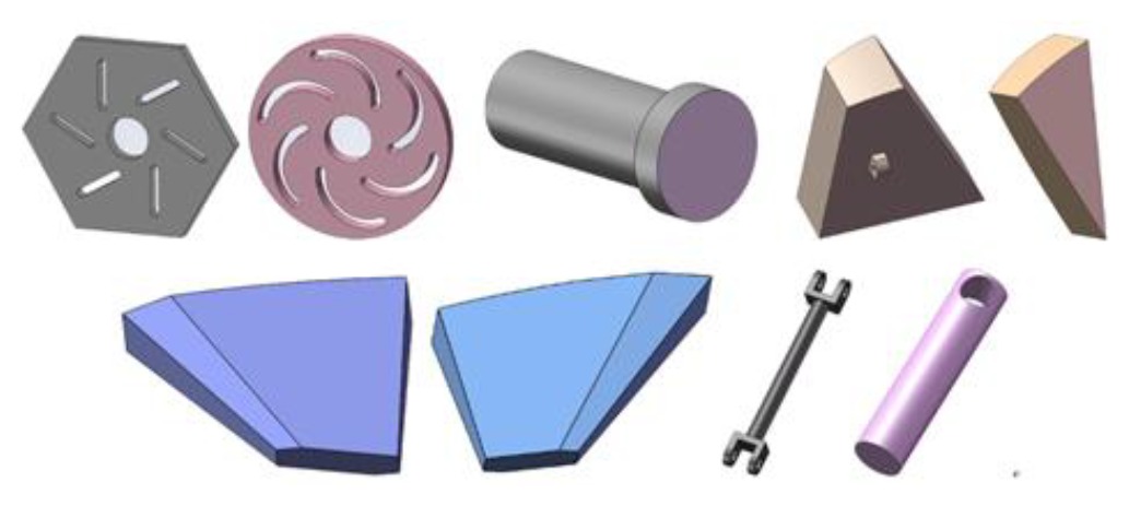
In order to save prototype development costs and improve the prototype development efficiency, the standard resin material and nylon PA6 material are used to print the parts. In order to reduce the connection clearance between the plates, 1 in. (3.33 mm) small hinges are selected for the rotating shaft between the plates. See Table 4 for the quantity and material of the main parts of the deformable wheel mechanism.
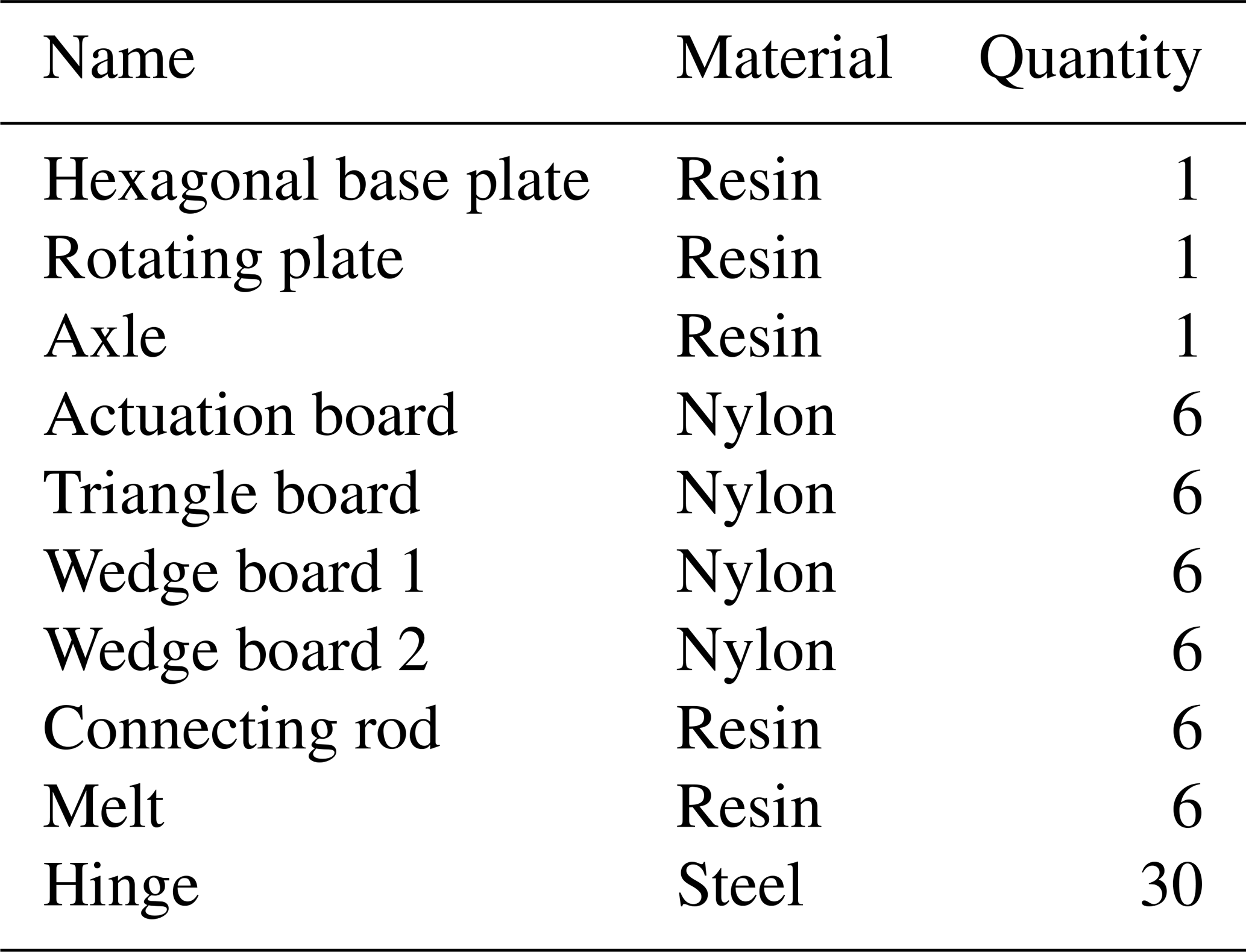
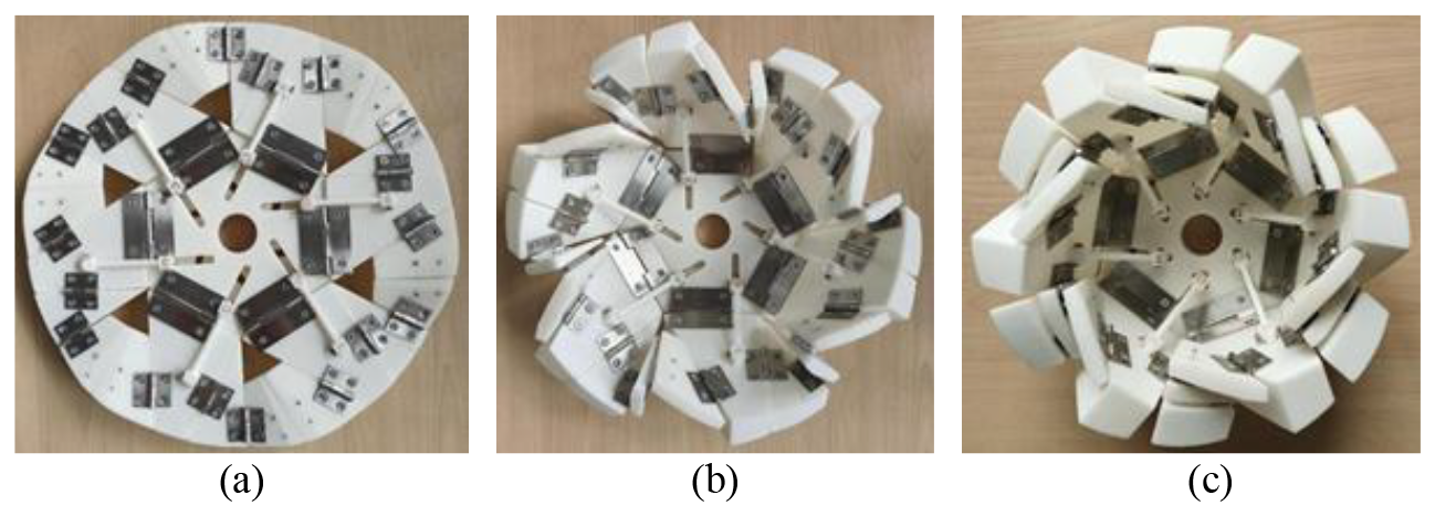
Figure 21Horizontal state of the prototype deformable wheel mechanism. (a) Folding state. (b) Middle folding state. (c) Unfolded state.
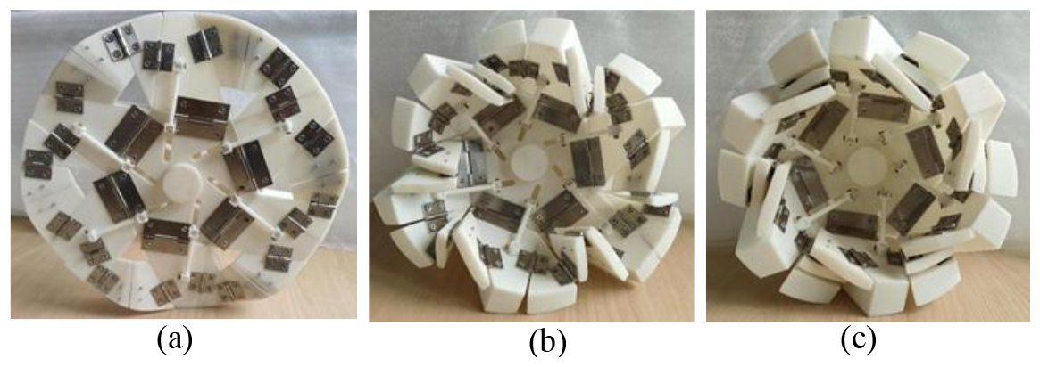
Figure 22Vertical state of the prototype deformable wheel mechanism. (a) Folding state. (b) Middle folding state. (c) Unfolded state.
The base plate, rotating plate, actuation plate, and wedge plate of the deformable wheel are connected by hinges to complete the assembly of the deformable wheel. The horizontal and vertical states of the deformable wheel principle prototype are shown in Figs. 21 and 22.
The discrepancy between the prototype in Fig. 21c and the complete circle shown in Fig. 9 has been noted. This difference arises from limitations in the current prototype design and construction process. In subsequent research, this issue will be addressed by refining the design and improving the manufacturing techniques to ensure that the prototype more closely matches the intended geometry, specifically achieving a complete circle.
Table 5Folding and spreading parameters of the deformed wheel mechanism.
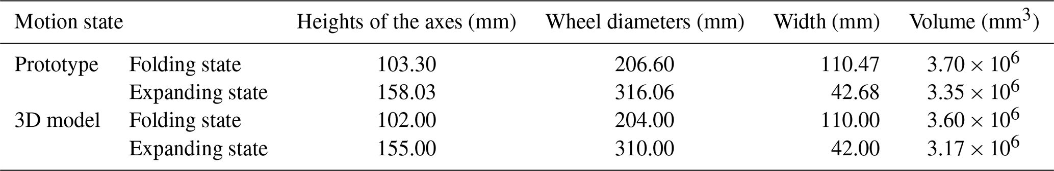
The dimensional parameters of the deformable wheel in the extended and folded states are shown in Table 5.
As shown in Table 5, the axial height of the deformable wheel in its folded state measures 103.30 mm, with a wheel width of 110.47 mm. In the unfolded state, the height of the axle center increases to 158.03 mm, while the wheel width decreases to 42.68 mm. The diameter ratio of the wheel in the deployed state compared to the folded state is 1.53, with the axle center height increasing by 53 %. This design allows vehicles with high obstacle-surmounting capabilities to enhance their adaptability to rough terrain by adjusting the height of the wheel's axle center. It can be seen from Table 5 that the dimensional parameters of the unfolded state and folded state of the unfolded wheel relative to the 3D model are increased due to certain errors generated during processing and assembly.
The experimental results of the prototype demonstrate that the deformable wheel mechanism exhibits excellent scalability, achieving full retraction and deployment without any jamming or interference. Through experimental validation, the principle prototype – constructed using nylon and resin materials – has been proven to deliver outstanding performance in terms of strength and rigidity while also benefiting from its lightweight design. This significantly enhances the prototype's reliability and adaptability. The experiments further confirm that the folding and unfolding movements of the deformable wheel can be realized efficiently through a single drive mechanism, such as a rotating plate. This highlights the structure's simplicity and high operational efficiency. The successful development of the prototype not only provides valuable insights for the engineering design of deformable wheels but also validates the applicability of nylon and resin materials in complex structural configurations. Future work will focus on further optimizing the structural parameters of the deformable wheel in order to enhance its performance and expand its potential in engineering applications.
To meet the demands of special vehicles for obstacle traversal and deformable wheel conditions, a deformable wheel mechanism based on the six-point paper-folding principle was developed. A regular hexagonal plate with fixed vertices minimizes ball hinge usage and reduces system degrees of freedom. Folding is achieved via a motor-driven crank-slider mechanism. Using the Jacobian matrix method, the degrees of freedom for single-vertex and multi-vertex paper-folding mechanisms (assuming zero thickness) were calculated, providing a theoretical basis for kinematic analysis and design optimization. The kinematic model of the deformable wheel mechanism was constructed using the improved D-H method, followed by performance evaluations of stiffness, folding ratio, and motion behavior. The diameter ratio of the unfolded to folded states is 1.53, with a 53 % increase in axial height, highlighting excellent deformability. Static simulations in ANSYS and dynamic simulations in ADAMS validated the mechanism's reliability and adaptability under diverse conditions. A prototype was fabricated using additive manufacturing with lightweight, high-strength resin material, enhancing precision and performance. The assembled prototype successfully demonstrated the folding and unfolding functionalities, with experimental tests confirming the folding rate. Additive manufacturing with resin materials enabled rapid realization of complex structures, improving stiffness and deformation stability and highlighting the approach's potential for innovative design and efficient manufacturing.
In future work, we will optimize the configuration of the deformable wheel mechanism to further enhance the stiffness and load-bearing capacity of the deformable wheel. At the same time, it is necessary to improve and optimize the drive and transmission units of the deformable wheel, thereby enhancing its deployment and retraction performance. Furthermore, additional sensors will be incorporated to further verify the actual operating parameters of the deformable wheel, followed by field tests on special vehicles to validate its practicality.
No data sets were used in this article.
Methodology: CS. Software: BXW. Investigation: FZ and GXZ. Writing – original draft preparation: YLW. Writing – review and editing: YYH. All of the authors read and agreed to the published version of the manuscript.
The contact author has declared that none of the authors has any competing interests.
Publisher's note: Copernicus Publications remains neutral with regard to jurisdictional claims made in the text, published maps, institutional affiliations, or any other geographical representation in this paper. While Copernicus Publications makes every effort to include appropriate place names, the final responsibility lies with the authors.
This research was funded by the Science and Technology Plan Project of Wenzhou Municipality (grant no. G20240076) and the Natural Science Foundation of the Jiangsu Higher Education Institutions of China (grant no. 23KJB460010).
This paper was edited by Daniel Condurache and reviewed by two anonymous referees.
Berre, J., Geiskopf, F., and Rubbert, L.: Origami-inspired design of a deployable wheel, in: New Advances in Mechanisms, Mechanical Transmissions and Robotics, MTM&Robotics 2020, Mechanisms and Machine Science, edited by: Lovasz, E. C., Maniu, I., Doroftei, I., Ivanescu, M., and Gruescu, C. M., Springer, vol. 88, https://doi.org/10.1007/978-3-030-60076-1_11, 2020.
Chai, S., Hu, Z., Chen, Y., You, Z., and Ma, J.: Programmable multi-stability of curved-crease origami structures with travelling folds, J. Mech. Phys. Solids, 168, 105073, https://doi.org/10.1016/j.jmps.2024.105877, 2024.
Endo, K., Wakimoto, S., and Suzumori, K.: Fabrication of origami wheel using pattern embedded fabric and its application to deformable mobile robot, in: 2014 IEEE International Conference on Intelligent Robots and Systems (IROS), Chicago, USA, 14–18 September 2014, IEEE, 451–456, https://doi.org/10.1109/IROS.2014.6942773, 2014.
Fang, H., Wang, M. J., and Wang, K. W.: 3D printing of origami structures for reconfigurable systems, J. Mech. Design, 139, 102301, https://doi.org/10.1115/1.4037230, 2017.
Felton, S., Tolley, M., and Demaine, E.: Origami-inspired active structures: A synthesis and review, Smart Mater. Struct., 23, 094001, https://doi.org/10.1088/0964-1726/23/9/094001, 2014.
Guo, J., Zhao, Y., Xu, Y., and Zhang, G.: Mechanics analysis and structural design of a truss deployable antenna mechanism based on 3RR-3URU tetrahedral unit, Mech. Mach. Theory, 171, 104749, https://doi.org/10.1016/j.mechmachtheory.2022.104749, 2022.
Guo, J., Zhao, Y., Xu, Y., and Zhang, G.: Configuration synthesis and lightweight networking of deployable mechanism based on a novel pyramid module, Chin. J. Mech. Eng., 36, 105, https://doi.org/10.1186/s10033-023-00934-1, 2023.
Kim, H., Lee, D., and Park, J.: Fabrication of soft actuators with complex deformation modes using 3D printing and UV-curable elastomers, Polymers, 12, 1784, https://doi.org/10.3390/polym12081784, 2020.
Kim, Y. and Kim, S.: Variable-diameter origami wheel for hybrid terrain mobility, Robotics, 8, 49, https://doi.org/10.3390/robotics8030049, 2019.
Kimura, A. and Ito, S.: Origami-Inspired Deformable Wheels for Disaster Response Robots, Robot. Auton. Syst., 129, 103538, https://doi.org/10.1016/j.robot.2020.103538, 2020.
Kong, F. and Cheng, Y.: Bio-inspired origami wheels for multi-terrain robot adaptation, J. Field Robot., 37, 1025–1043, https://doi.org/10.1002/rob.21958, 2020.
Lee, D., Jung, G., Sin, M., Ahn, S., Cho, K.: Deformable Wheel Robot Based on Origami Structure, IEEE-ASME T., 18, 75–85, https://doi.org/10.1109/ICRA.2013.6631383, 2013a.
Lee, D., Koh, J., Kim, J., Kim, S., and Cho, K.: Deformable-wheel robot based on soft material, Int. J. Precis. Eng. Man, 14, 1439–1445, https://doi.org/10.1109/ICRA.2013.6631383, 2013b.
Li, Y., Zhang, F., Liu, Y., and Leng, J.: 4D printed shape memory polymers and their structures for biomedical applications, Sci. China. Technol. Sc., 63, 545–560, https://doi.org/10.1007/s11431-019-1494-0, 2020.
Liu, J. and Chen, T.: Kinematic analysis of folding patterns in origami wheels, J. Mech. Robot., 13, 041004, https://doi.org/10.1115/1.4054170, 2021.
Masana, R. and Daqaq, M. F.: Origami-inspired composite springs with bi-directional translational-rotational functionalities, arXiv [preprint], https://doi.org/10.48550/arXiv.2306.02145, 3 June 2023.
Miura, K. and Nakamura, T.: Origami engineering for space deployable structures, Acta Astronaut., 109, 42–51, https://doi.org/10.1016/j.actaastro.2015.03.002, 2015.
Miyashita, S. and Rus, D.: Additive manufacturing of origami structures for biomedical applications, Adv. Mater., 29, 1606503, https://doi.org/10.1002/adma.201606503, 2017.
Overvelde, J. T. B., Weaver, J. C., and Hoberman, C.: Additive manufacturing of multi-material origami structures, Nature, 541, 347–352, https://doi.org/10.1038/nature20794, 2017.
Rus, D. and Tolley, M. T.: Additive manufacturing of soft robots: Challenges and opportunities, Nature, 521, 467–475, https://doi.org/10.1038/nature14543, 2015.
Shao, J., Yu, L., Skov, A. L., Zhao, Q., and Zhou, D.: Highly stretchable conductive MWCNT–PDMS composite with self-enhanced conductivity, J. Mater. Chem. C, 8, 13389–13395, https://doi.org/10.1039/d0tc01735c, 2020.
Wang, C., Guo, H., Liu, R., Deng, Z., Chen, Y., and You, Z.: Reconfigurable Origami-Inspired Multistable Metamorphous Structures, Sci. Adv., 10, eadk8662, https://doi.org/10.1126/sciadv.adk8662, 2024a
Wang, D., Fang, B., and Zheng, J.: Design and research of a deformable wheel-leg robot based on origami mechanism, P. I. Mech. Eng. C-J. Mec., 238, 8769–8784, https://doi.org/10.1177/09544062241241417, 2024b.
Wang, Y., Zhang, Q., and Du, H.: Recent progress in 4D printing of smart polymer materials, Polymers, 11, 115, https://doi.org/10.1007/s11431-019-1443-1, 2019.
Xue, W., Jian, B., Jian, L., Wang, R., and Ge, Q.: Origami Robots: Design, Actuation, and 3D Printing Methods, Adv. Mater. Technol., e00278, https://doi.org/10.1002/admt.202500278, online first, 2025.
Yin, H., and Feng, L.: Bio-Inspired Origami Wheels for Multi-Terrain Robots, J. Field Robot. 36, 1025–1038, https://doi.org/10.1002/rob.21962, 2019.
Zhang, G., Wang, J., Guo, J., He, J., Xu, Y., and Zhao, Y.: A novel single-DoF deployable antenna mechanism based on heterogeneous modules: Configuration design and performance analysis, Thin Wall. Struct., 203, 112232, https://doi.org/10.1016/j.tws.2024.112232, 2024.
Zhang, J. and Ng, T. W.: Deployable wheels using additive manufacturing and origami techniques, Additive Manufacturing, 35, 101327, https://doi.org/10.1016/j.addma.2020.101327, 2020.
- Abstract
- Introduction
- Calculation of the freedom of a deformable wheel mechanism
- Kinematics of the deformable wheel mechanism
- Optimization and analysis of the deformable wheel configuration
- Research on the principle prototype of the deformable wheel mechanism
- Conclusions
- Further work
- Data availability
- Author contributions
- Competing interests
- Disclaimer
- Financial support
- Review statement
- References