the Creative Commons Attribution 4.0 License.
the Creative Commons Attribution 4.0 License.
 | 13 Jun 2025
Frame design and improvement of a small electric vehicle
Zhongming Wu
Wenjie Pan
Ruikun Niu
Lijuan Liu
The frame is a crucial component of a small electric vehicle. As the main body that bears the load, it has requirements for strength and deformation, meanwhile avoiding resonance with road excitation. Light-weighting of the frame can reduce vehicle cost while meeting performance requirements. This article designs a type of small electric vehicle frame, uses the CATIA 3D modeling software to model the frame entity, and then uses the ANSYS finite-element software to perform simulation analysis of the frame model, obtaining its deformation and stress conditions under the corresponding working conditions. Under the guarantee of frame safety, adjustments and optimizations of the frame dimensions are carried out, and their rationality is verified through simulation. Finally, the light-weighting of the structural design is achieved while meeting the requirements for strength and rigidity. The results show that the optimized frame meets the safety performance requirements and that the overall deformation and stress distribution are reasonable, ultimately achieving a weight reduction target of 10.7 % and realizing the light-weighting goal of the frame.
- Article
(3323 KB) - Full-text XML
- BibTeX
- EndNote


With the development of electric vehicles, light-weighting, modularization, and integration of automobiles have become research hotspots in the current automotive industry (Kim et al., 2018; Sehmi et al., 2020; Hunar et al., 2020). Light-weighting of automobiles helps improve the endurance mileage of pure electric vehicles, while modularization and integration enable the integration of parts into a whole, improving the assembly efficiency of automotive parts (Chen et al., 2021). The frame is the installation carrier for electric vehicle batteries, bodies, suspensions, etc., and it is the core structure that ensures stable, safe, and reliable driving of the vehicle. Minimizing the mass of their frames can increase the endurance mileage of electric vehicles (Chen et al., 2021; Cui et al., 2019; Yang et al., 2019). Light-weighting of the automobile body combines lightweight materials with structural optimization design to obtain the optimal solution with minimal mass under the condition of meeting strength and stiffness requirements, thus achieving the purpose of light-weighting (Zhang et al., 2019).
At present, there are many studies on light-weighting of vehicles at home and abroad, but there are relatively few studies on body frames. Tang Pei (2024) proposed a multi-objective topology optimization method combining analytical hierarchy process (AHP) and topology optimization for lightweight design of vehicles. Using AHP to determine the weight of each working condition, a multiple-working-condition topology optimization design was implemented, and the weight of the vehicle body was reduced by 16.5 kg (Tang et al., 2024). Based on the variable density method, Ma et al. (2023) designed the global topology optimization of the structure to obtain the distributed design materials, realize the efficient utilization of the materials, and improve the torsional stiffness design (Ma et al., 2023). By using effective big-data mining tools, Du et al. (2023) proposed a dynamic design methodology to establish a technical platform for multidisciplinary design optimization for high-speed vehicles, and they created an adaptive improvement scheme with an optimal parameter configuration (Du et al., 2023). Liu et al. (2024) studied the aspects of material design accuracy, lap structure design, simulation, and process manufacturing and solved the contradiction between power battery size and layout space, unreasonable layout position, and load distribution (Liu et al., 2024). Fu Bin et al. (2023) quantitatively analyzed the influence of vehicle light-weighting on wheel wear and rolling contact fatigue (RCF) by using the wear law and other methods. This design can reduce wheel wear by about 40 % and shows significant advantages in preventing RCF damage. This study takes a new energy tractor frame as its research object, takes the current demand for frames in electric vehicles, and utilizes the equal-strength principle and the iterative optimization method. It focuses on lightweight design of frames using an investment casting aluminum alloy as the main material, and it optimizes the local structure. The development of a lightweight new energy tractor aluminum alloy frame has positive significance for solving the problems encountered in the development of electric vehicles.
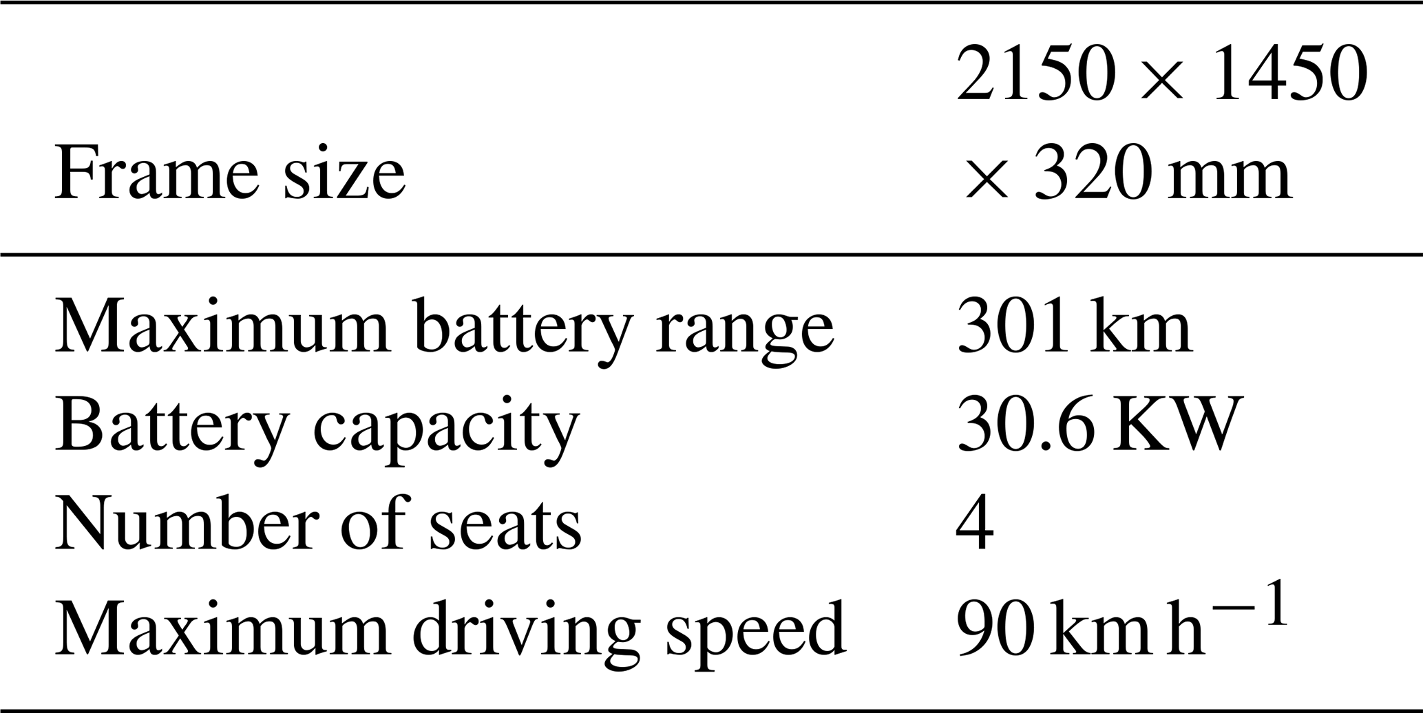
In this paper, the small ant model car of China Chery Automobile Co., Ltd. is taken as the research object, and the size data are provided internally by China Chery Automobile Co., Ltd., with the specific parameters shown in Table 1.
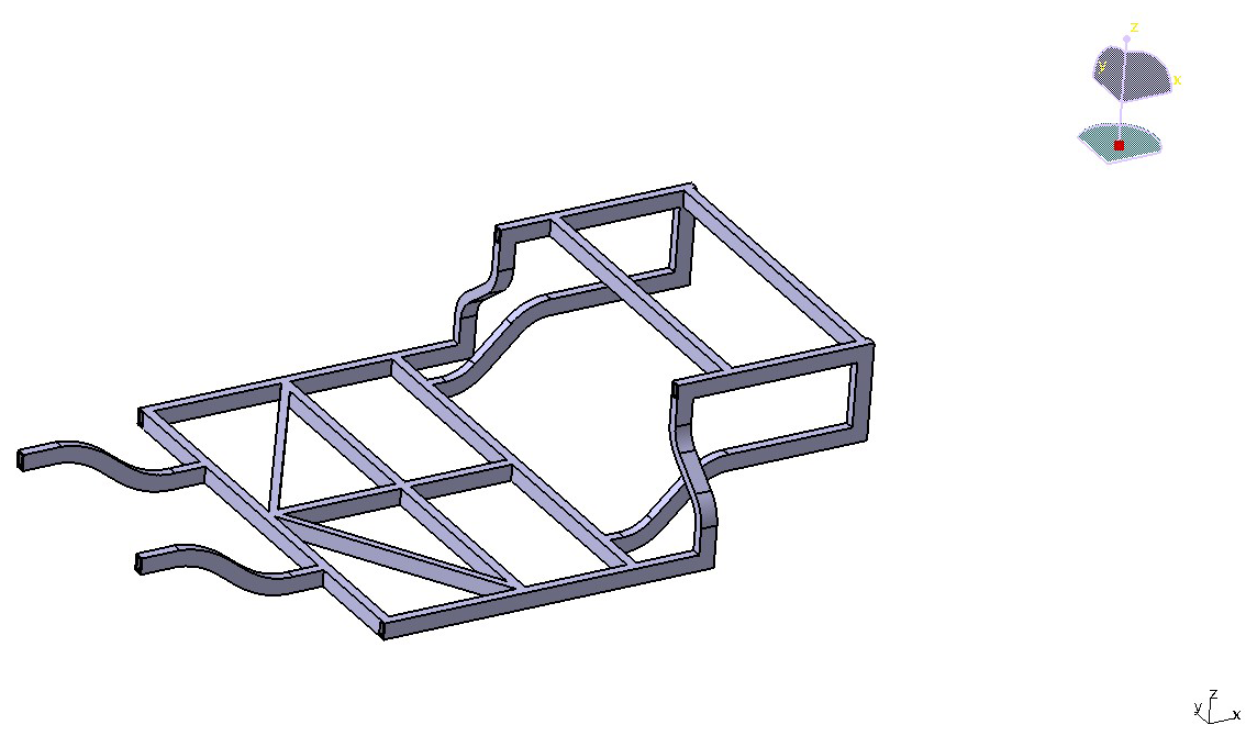
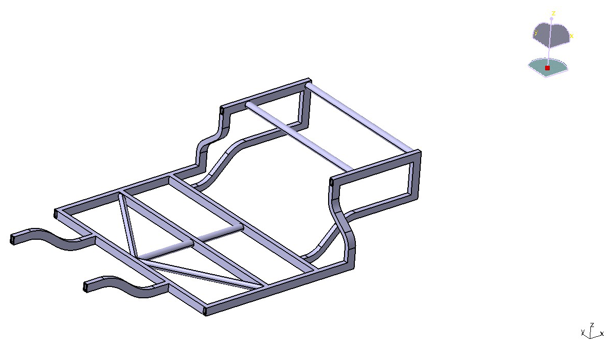
The frame of this small electric vehicle measures 2150 mm in length and 1450 mm in width. The entire frame is welded together using rectangular steel tubes with dimensions of 50 mm × 30 mm × 6 mm. During the geometric modeling process for the frame of this small electric vehicle, simplifications can be made by not considering all of the welding points, welds, and process holes on the frame. Additionally, structural chamfers and fillets are modified to right angles to ensure a smooth and rounded structural surface. Following the simplified process, the model was necessarily simplified to meet the requirements for simplified structure and analysis. A 3D model was created using the CATIA software, as shown in Fig. 1 below. The frame weighs 97.278 kg.
The frame of the small electric vehicle is made of Q345 steel material. Both the crossbeam and the longitudinal beam are welded from rectangular steel tubes.
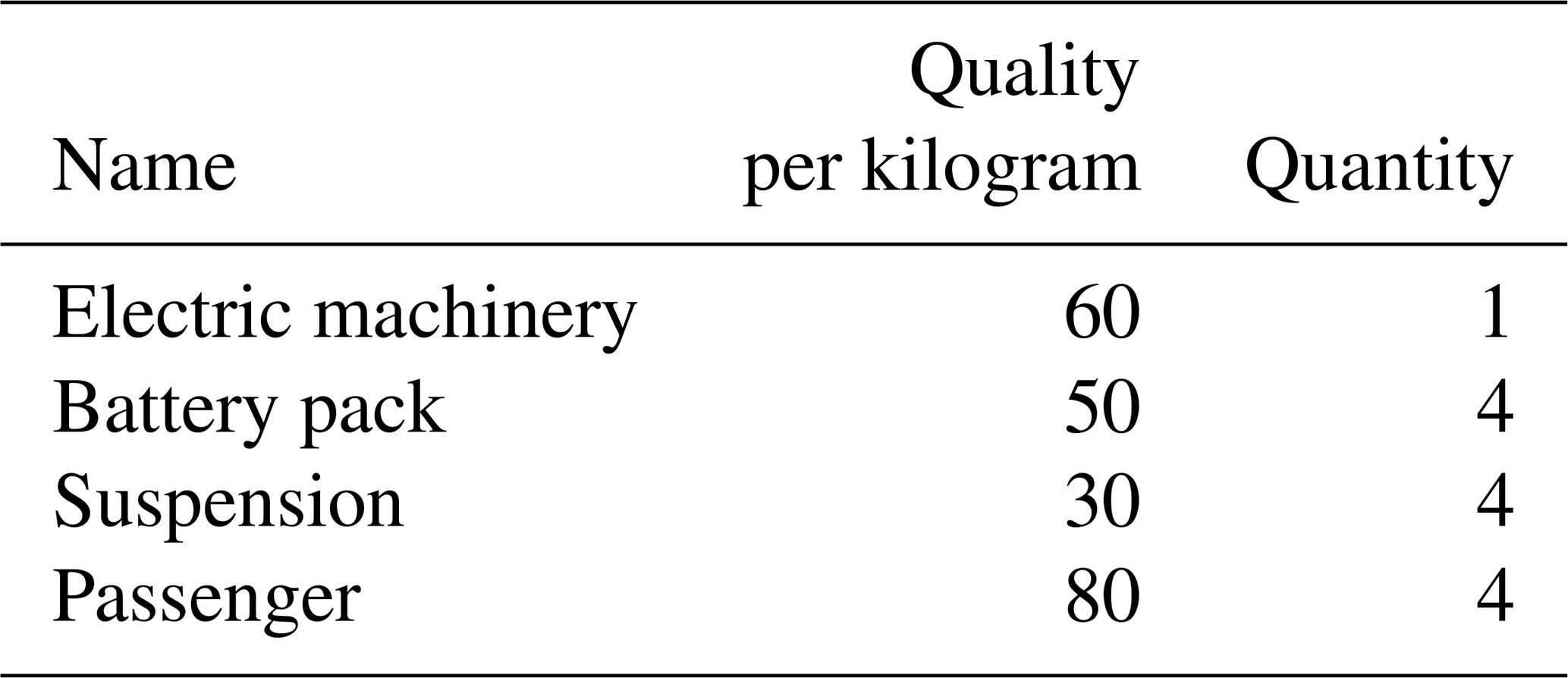
The load borne by the frame primarily consists of the motor, occupants, suspension, and battery pack. The mass parameters of each component are presented in Table 2.
3.1 Analysis of the working condition of the frame with all four wheels on the ground under full load
Under the conditions of being fully loaded and with all four wheels on the ground, the main loads borne by the frame structure come from the weight of the frame itself, the weight of the various components, and the weight of the occupants. The total weight is linearly related to the dynamic load factor, with a maximum value of 1.7 selected for the dynamic load factor to assist in checking the performance of the chassis structure. After calculations using finite-element software, the results are shown in Figs. 2 and 3. Figure 2 is an equivalent displacement distribution diagram, and Fig. 3 is a stress distribution contour plot.
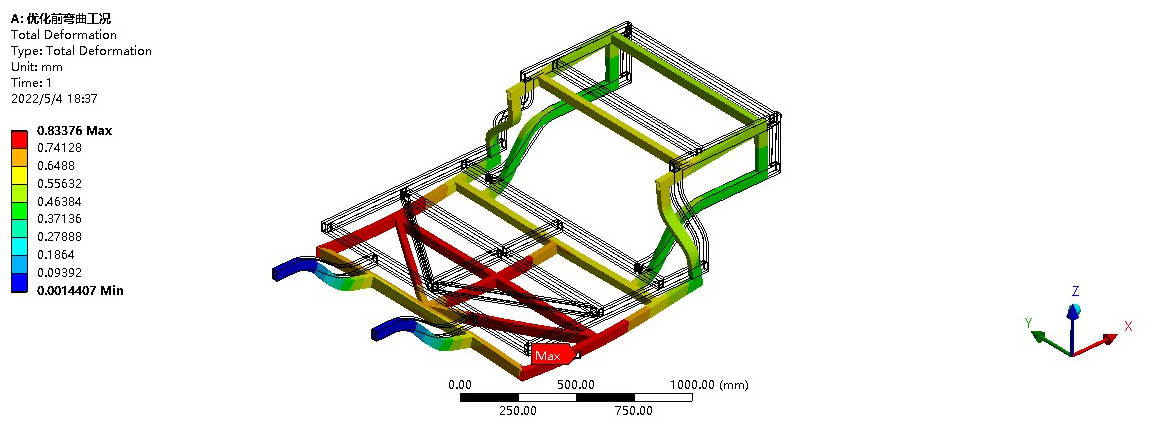
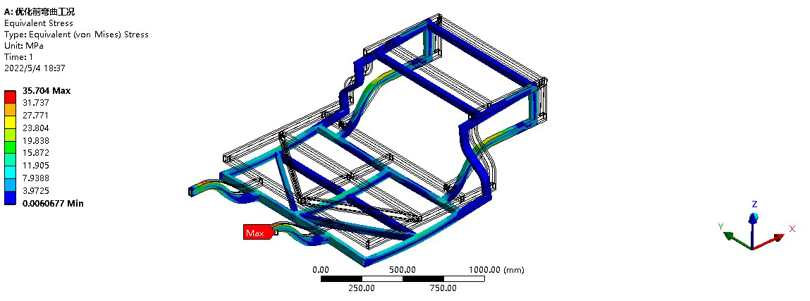
From the deformation distribution diagram shown in Fig. 2, it can be seen that, under the conditions of the electric vehicle frame being fully loaded and all four wheels being grounded, the maximum displacement of deformation is 0.83376 mm. The maximum deformation occurs at the middle beam of the frame, gradually decreasing towards the rear of the frame. The deformation at the front end of the frame is relatively small and can be neglected. The maximum deformation of the frame is much smaller than the allowable deformation of the material, so under this condition the rigidity requirements of the frame can be met. From the stress cloud diagram shown in Fig. 3, it can be seen that, when the frame is driven at a constant speed in a straight line, the location where the maximum stress may occur is the connection of the front seats, with a value of 35.704 MPa, which is much smaller than the yield strength of the Q345 frame material. Therefore, the strength also meets the requirements.
3.2 Analysis of the working condition where one side of the front wheel is suspended before full loading
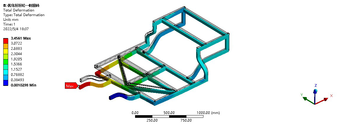
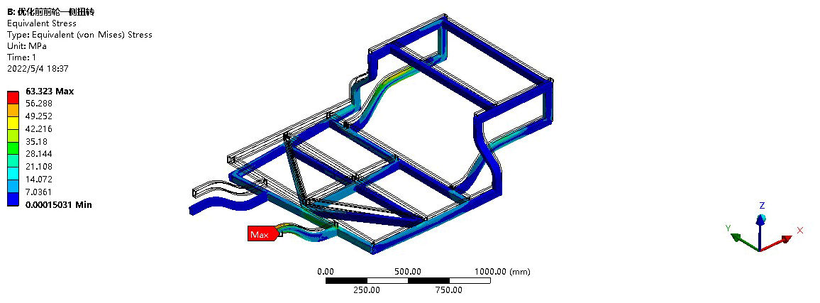
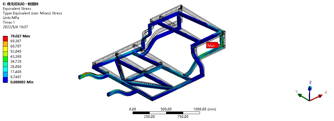
The simulated road condition for this scenario is harsh, with uneven ground causing the vehicle body to sway and jolt. When the car is in this condition, there may be a situation where one of the tires becomes suspended or lifted. At this time, the deformation of the entire vehicle frame is relatively large, and the structure of the chassis or frame may undergo severe torsion. The speed of a small electric vehicle under this condition generally does not exceed 60 km h−1, so the resulting inertial load is relatively small and the dynamic load setting is taken as 1.3. An omnidirectional constraint of x, y, and z displacement and rotation is applied to the right front wheel, and a vertical constraint is applied to the rear wheels. The weight of the frame is achieved by applying vertical acceleration of gravity, and the weight of the other parts is applied as concentrated and uniformly distributed loads according to the corresponding node positions while contacting the suspension and tire weight of the right front wheel. After calculation using the finite-element software, the displacement stress results of the frame under the condition of one front wheel being suspended are shown in Figs. 4 and 5.
As can be seen from the deformation distribution diagram in Fig. 4, the maximum deformation under this condition is 3.4561 mm, occurring at the suspension of the right front wheel. This value still meets the maximum deformation allowable for the material. According to the stress distribution diagram in Fig. 5, when the car is fully loaded and one wheel is suspended, the maximum stress occurs at the left suspension, with a value of 63.323 MPa. Compared to the allowable yield strength of the material, there is still a significant margin of strength, meeting the strength requirements.
3.3 Analysis of the working condition where one side of the rear wheel is suspended after full loading
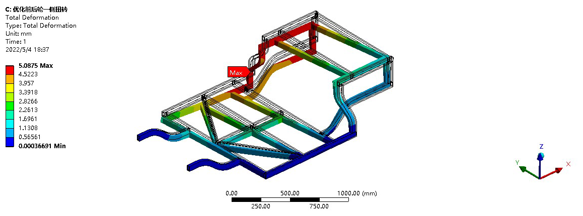
The situation with the rear wheels suspended is largely similar to that with the front wheels suspended, but there are slight differences in terms of constraints and loads. The specific conditions are similar to those with one side of the front wheels suspended, and the dynamic load factor is taken as 1.3. In terms of boundary conditions, full degrees of freedom in the x, y, and z directions are imposed on both front wheels, while the translational degree of freedom in the z direction is removed from the right rear wheel and the vertical degree of freedom and other rotational degrees of freedom are constrained for the left rear wheel (He et al., 2020; Shan et al., 2023). The weight of the frame is obtained by setting the acceleration due to gravity, and the weight of the other vehicle components and occupants is applied as corresponding concentrated and uniformly distributed loads at the corresponding node positions. The displacement stress results of the frame under the condition with one side of the rear wheels suspended are shown in Figs. 6 and 7.
As can be seen from the results presented in Figs. 6 and 7, the maximum displacement of the frame under this condition is 5.0875 mm, occurring at the right rear wheel, where the constraint is released. Compared to the maximum allowable deformation of the material, the stiffness requirement is met. When the right rear wheel is suspended, the maximum stress occurs at the left rear wheel suspension, with a value significantly lower than the material yield strength.
3.4 Analysis of emergency braking under full-load conditions
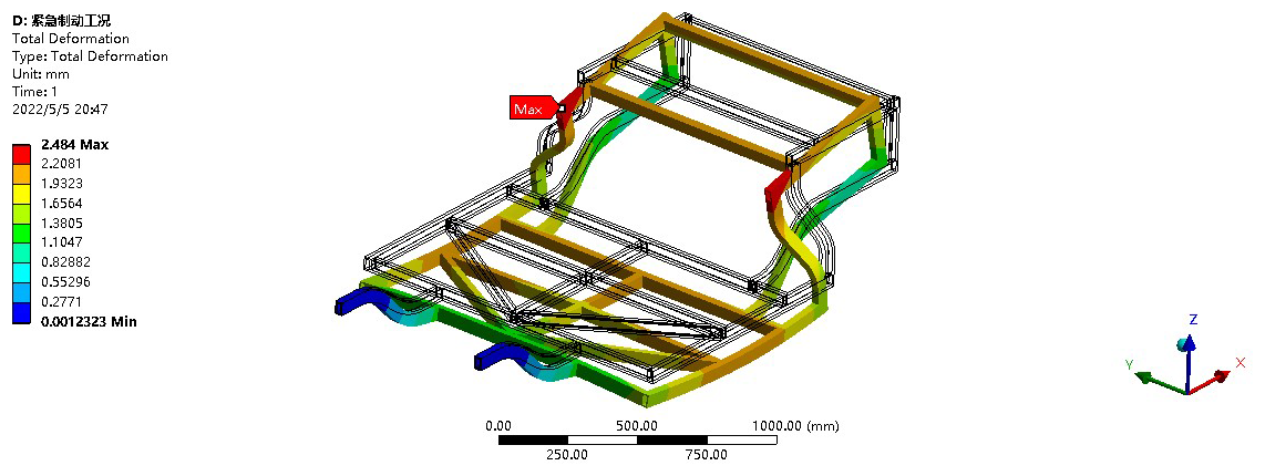
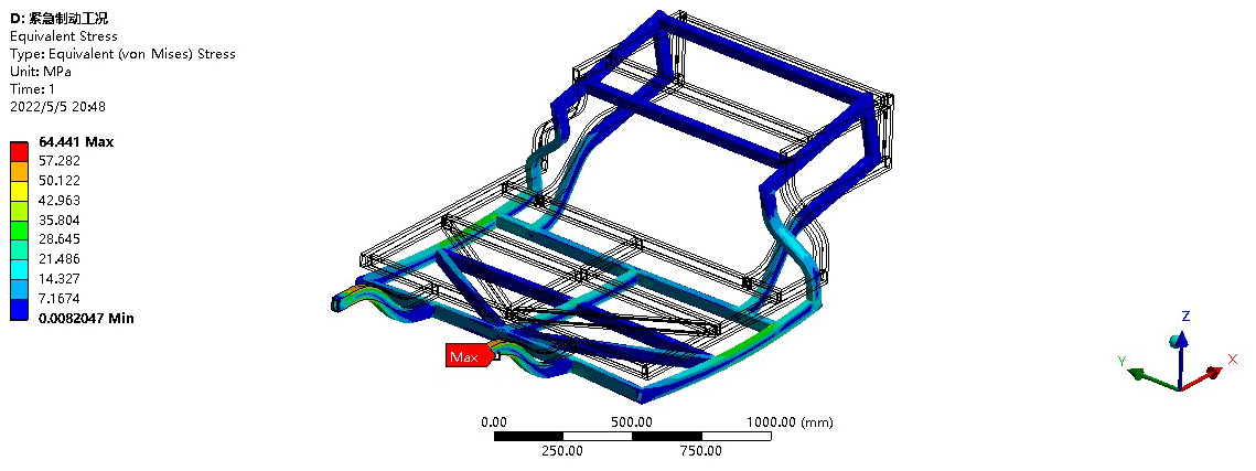
During the driving process, the vehicle may encounter sudden deceleration or braking conditions. During this process, the entire vehicle will be subjected to a sudden and strong load. Therefore, it is necessary to simulate emergency braking to test whether the frame can meet the strength and stiffness requirements of emergency braking conditions. Generally, the ABS (anti-lock braking system) is triggered during emergency braking to prevent complete tire lockup. However, for the analysis, we set the extreme condition of complete tire lockup during emergency braking, assuming that the braking deceleration of small electric vehicles is 7.84 m s2 (approximately 0.8 g), which is the same as that of general vehicles during emergency braking, and the dynamic load factor is taken as 1.5. The largest deformation occurs in the rear half of the frame, with a value of 2.484 mm, as shown in Fig. 8. The reason for this is that the rear half receives a larger force during deceleration. The maximum stress during emergency braking occurs in the front half of the frame at the joint between the frame and the suspension, with a maximum value of 64.441 MPa, as shown in Fig. 9, which is far less than the allowable strength of the material.
3.5 Analysis of operating conditions during full-load sharp turns
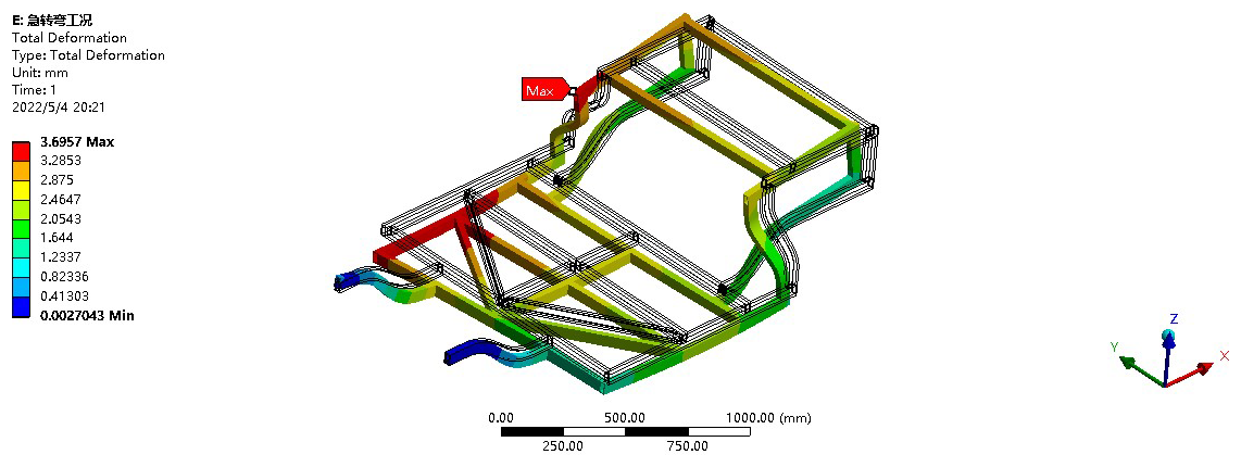
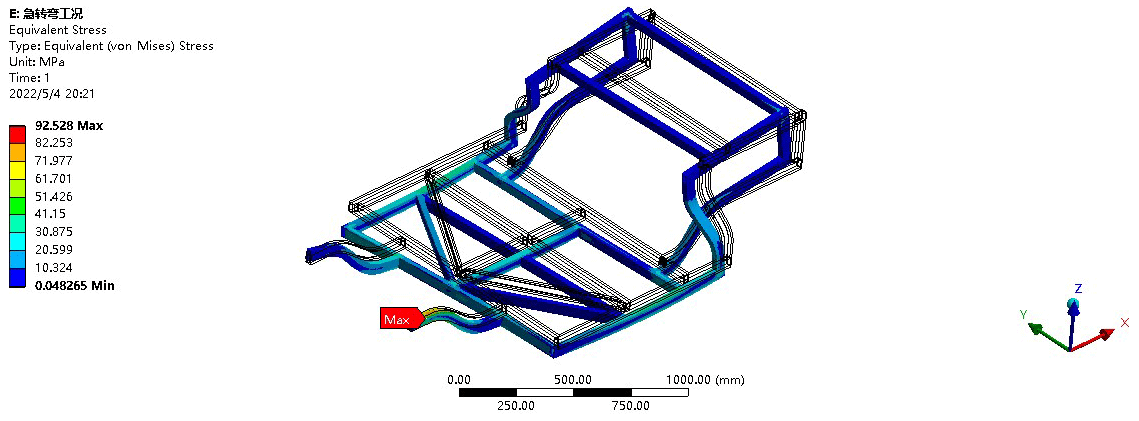
When a car encounters a sudden obstacle during driving, it needs to make a sharp turn to avoid colliding with the obstacle. During the sharp turn, the car frame will tilt to one side under the action of centrifugal force, and the degree of tilt will be directly related to the initial speed and turning radius and will also produce deceleration acceleration (Wang et al., 2024). This section simulates a real situation by applying lateral and longitudinal accelerations of 0.2 to the frame to simulate the emergency left turn of a small electric vehicle encountering an obstacle. In addition, the magnitude of the centrifugal force on the frame is affected by the mass of the entire vehicle. Under this condition, it is assumed that the rear axle of the electric vehicle is completely side-slipping, and the dynamic load factor is set to 1.4. When a small electric vehicle makes a sharp left turn, the left part of the vehicle tends to tilt upward and the right part tends to tilt downward. Therefore, the weight of the suspension and tires should be applied to the corresponding position in the right half, and other weights should be applied to the corresponding node positions.
When a small electric vehicle makes a sharp left turn, due to the effects of lateral and longitudinal acceleration, the frame structure tends to tilt towards the upper right. Since the lateral stiffness of the left and right parts is the same, the tilt amplitude is not large, with a maximum deformation of 3.6957 mm, which is not significant. The deformation of the entire vehicle is relatively concentrated on the right part of the frame, with the maximum deformation occurring in the right rear part of the frame. The maximum stress value is 92.528 MPa, which is less than the yield strength of the material, thereby meeting the strength requirements. The stress displacement distribution of the frame structure under full-load emergency turning conditions is shown in Figs. 10 and 11.
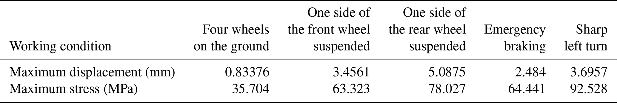
The static analysis of the frame structure, by applying corresponding constraints and loads, simulates five typical operating conditions of a micro electric vehicle driving on real roads, such as sharp turns and sudden braking, to obtain the strength and stiffness characteristics of the frame. The stress displacement contour maps for each operating condition indicate that both the strength and stiffness meet the safety requirements, as shown in Table 3. They also demonstrate that there is still room for light-weighting of the frame, providing an analytical basis for subsequent light-weighting efforts.
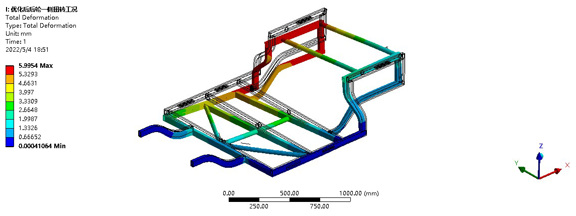
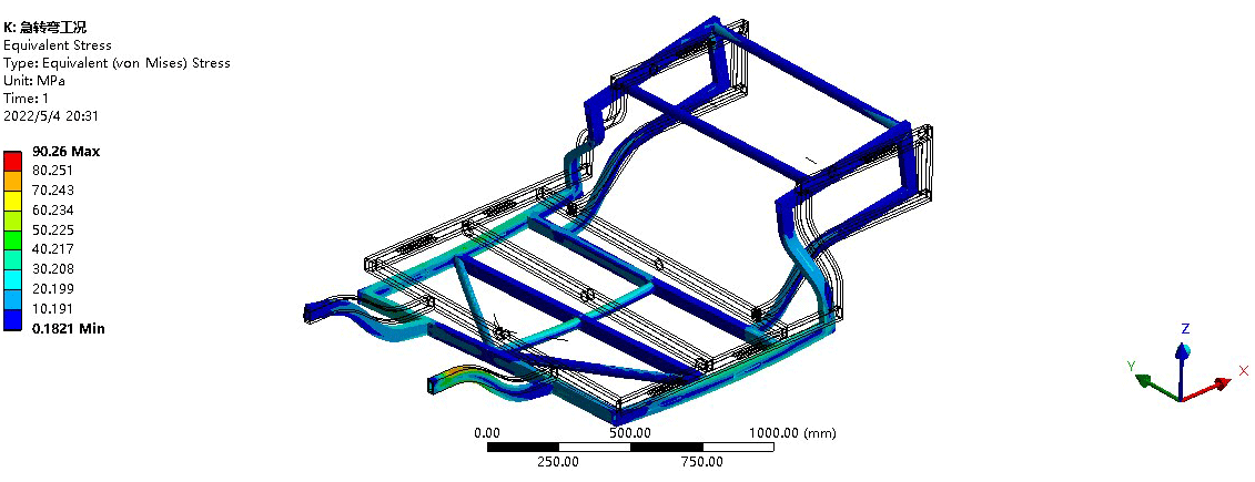
Table 4Frame optimization of the front and rear deformation contrast.
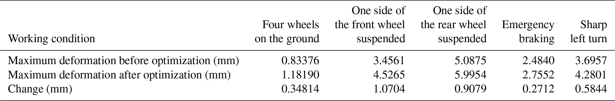
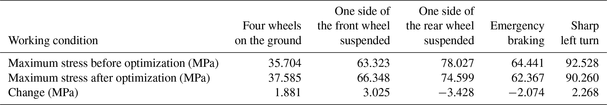
Table 6Comparison of natural frequencies before and after frame optimization.
4.1 Light-weighting improvement
Lightweight design is rooted in optimization theory for engineering research. Its model represents a mathematical abstraction of practical optimization design problems, expressing necessary constraints through inequalities or equations, solving for the range of design variable values, and achieving the optimal value of the objective function to meet the optimization goal. Generally, there are three methods: the first is to replace the original material with lightweight materials; the second is to use advanced formation processes to reduce the mass increase caused by the process; and the third is structural optimization design, including cross-sectional size optimization, shape optimization, and topology optimization (Cao et al., 2024). Based on the structural form of the frame, the cross-sectional size and shape of the frame components are used as variables for optimization design, with the frame mass as the objective function to minimize it. The main approach used in this article is the third method, which involves changing the cross-sectional size of the frame structure to achieve weight reduction (Wu et al., 2021).
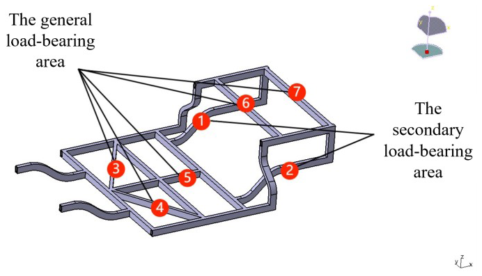
During the aforementioned static analysis process, the vehicle frame can be divided into three parts based on the specific load-bearing conditions and the corresponding deformation: the primary load-bearing area, the secondary load-bearing area, and the general load-bearing area. The main basis for dividing these three areas is the frequency and feedback effect of each part under various working conditions. The area that experiences the highest number of load applications and the greatest impact from the load is classified as the primary load-bearing area, and the other parts are classified accordingly. Through analysis of the static finite-element results, the two longitudinal beams (1 and 2) at the rear of the frame are classified as the secondary load-bearing area, while the two support bars and longitudinal beams in the middle of the frame, as well as the two cross beams (3, 4, 5, 6, and 7) at the rear of the frame, are classified as the non-primary load-bearing area. The specific division is shown in Fig. 12.
When the strength or stiffness of a material in a certain area meets the requirements but there is still an excessive surplus, this part becomes an area for light-weighting improvement.
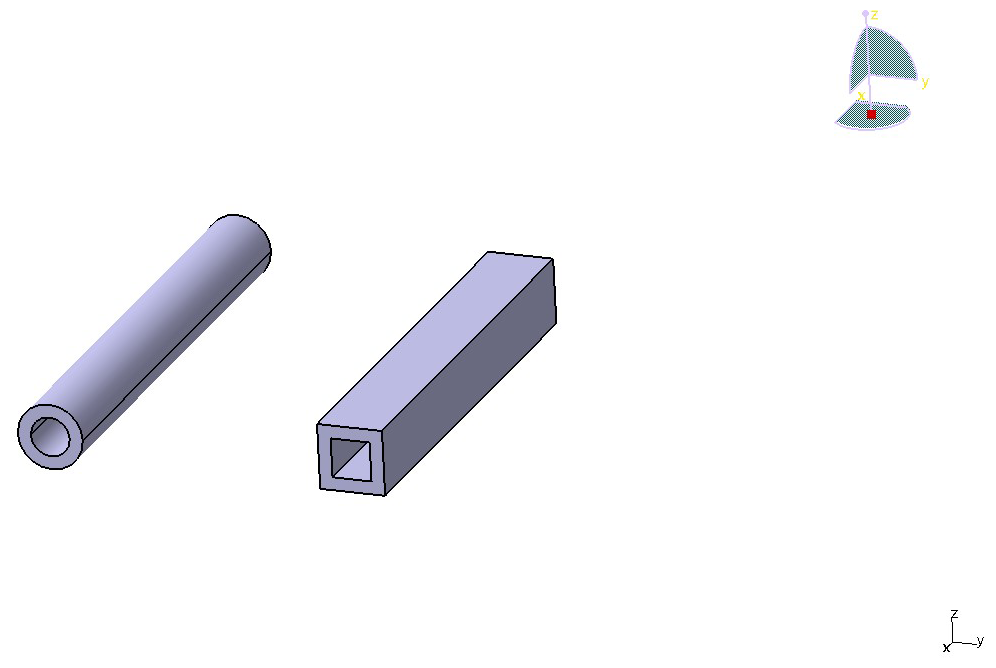
The main approach to enhancing the frame's strength is to alter the cross-sectional shape, with specific details to be discussed later. For the primary load-bearing areas, specifically rectangular steel tubes 1, 2, and 3, due to the load they experience at their structural locations and the need to ensure adequate rigidity and strength, the original rectangular steel tubes of 50 mm × 30 mm × 5 mm have been replaced with Φ30 mm × 6 mm circular steel tubes. For the non-primary load-bearing areas, i.e., rectangular steel tubes 4 and 5, due to their lower frequency of load exposure and higher reserve strength and rigidity, rectangular steel tubes of 30 mm × 30 mm × 6 mm have been substituted. The other parts remain unchanged.
The specific shape of the tubing is shown in Fig. 13. The optimized frame structure is shown in Fig. 14, with a mass of 89.364 kg.
4.2 Static analysis of the optimized frame
After optimization, a simulation analysis is conducted. Under static or uniform speed conditions, the maximum deformation of the optimized frame under stress is 5.9954 mm, and the maximum stress after optimization is 90.260 MPa. The results are shown in Figs. 15 and 16. The comparison of deformation and application data before and after optimization is shown in Tables 4 and 5. Compared with before optimization, the overall stress distribution of the frame is more uniform, indicating that the optimization results are relatively satisfactory.
4.3 Modal analysis of the optimized frame
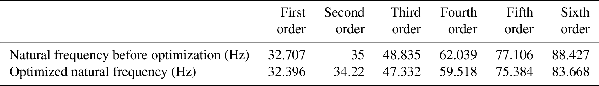
The modal analysis of the optimized frame is still conducted based on its sixth-order natural frequency and mode shape, exploring whether there is any overlap between the distribution of natural frequencies and the main road excitation. The results show that there is no overlap, and resonance will not occur (Stolz and Fang, 2025; Wu et al., 2020).
The comparison of natural frequencies before and after the modal analysis is shown in Table 6.
Based on the CATIA 3D software, a model of a small electric vehicle frame was created. After simplifying the frame model, it was imported into the ANSYS Workbench project of the finite-element software. Using the ANSYS software, a static analysis was conducted of the frame structure, simulating five typical operating conditions during vehicle driving. Stress–strain data under each condition were calculated, and the locations of the maximum strain and stress of the frame were obtained. Under structural deformation and stress safety, structural optimization design was carried out by adjusting the cross-sectional shape and size of the frame and adding weight-reducing holes, enabling the frame to maintain safety performance while achieving a lower weight. At the same time, modal analysis was conducted of the frame to obtain the natural frequencies and vibration modes of each order before and after optimization. The obtained natural frequencies were compared with road excitation in order to analyze their overlap and its impact on frame performance. The analysis showed that the frame structure would not resonate with road excitation. Through optimization design, the frame mass was reduced from the original 97.278 to 86.864 kg, achieving a weight reduction of 10.7 % overall, and the strength, stiffness, and deformation were within acceptable limits, achieving the goal of light-weighting and providing a certain reference value for related engineering design.
The data are available from the authors.
WZ and PW discussed and decided on the methodology of the study, and they prepared the manuscript. NR contributed to the prototype and the test. LL contributed to the model building.
The contact author has declared that none of the authors has any competing interests.
Publisher's note: Copernicus Publications remains neutral with regard to jurisdictional claims made in the text, published maps, institutional affiliations, or any other geographical representation in this paper. While Copernicus Publications makes every effort to include appropriate place names, the final responsibility lies with the authors.
This research is partly supported by the projects of the National Natural Science Foundation of China (grant no. 52075232).
This paper was edited by Daniel Condurache and reviewed by two anonymous referees.
Cao, F., Sheng, G., and Feng, Y.: Detection dataset of electric bicycles for lift control, Alexandria Eng. J., 10, 736–742, https://doi.org/10.1016/j.aej.2024.08.068, 2024.
Chen, J., Kwak, Y., Xu, M., Kurniawan, R., Li, C., and Ko, T.: Topology and modular size optimization of small electric vehicle frame based on cross-section contribution analysis, Struct. Multidiscip. O., 64, 4287–4304, https://doi.org/10.1007/s00158-021-03075-y, 2021.
Cui, X., Wang, X., and Yuan, S.: Effects of mechanical property parameters on wrinkling behavior of thin-walled tubes in hydroforming process, Int. J. Adv. Manuf. Technol., 100, 729–740, https://doi.org/10.1007/s00170-018-2706-2, 2019.
Du, W., Piao, S., Piao, M., Nie, C., Dang, P., Li, Q., and Tao, Y.: Multidiscipline Design Optimization for Large-Scale Complex Nonlinear Dynamic System Based on Weak Coupling Interfaces, Appl. Sci.-Basel, 13, 5532–5542, https://doi.org/10.3390/app13095532, 2023.
Fu, B., Qin, L., Luo, S., Ma, W., and Bruni, S.: Impacts of vehicle light-weighting on wheel wear and RCF and a novel ultralight vehicle design, Wear, 12, 119–126, https://doi.org/10.1016/j.wear.2023.205119, 2023.
He, T., Xu, Y., Huo, Y., Du, X., Yi, X., and Dong, X.: Effects of process parameters on microstructure and mechanical properties of ZL114A alloy under directional solidification, Mater. Express, 10, 1109–1115, https://doi.org/10.1166/mex.2020.1723, 2020.
Hunar, M., Jancar, L., Krzikalla, D., Kaprinay, D., and Srnicek, D.: Comprehensive view on racing car upright design and manufacturing, Symmetry, 12, 1020, https://doi.org/10.3390/sym12061020. 2020.
Kim, S. I., Kang, S. W., Yi, Y. S., Park, J., and Kim, Y. Y.: Topology optimization of vehicle rear suspension mechanisms, Int. J. Numer. Meth. Eng., 113, 1412–1433, https://doi.org/10.1002/nme.5573, 2018.
Liu, B., Yang, Jian., Li, J., Liao, X., Yang, Q., Zhang, J., Hu, T., and Jiang, S.: Research on welding deformation control technology of battery electric vehicle framed aluminum body, Prog. Nat. Sci., 2024, 34, 108–121, https://doi.org/10.1016/j.pnsc.2024.02.002, 2024.
Ma, W., Lu, Y., Wang, P., Wang, Y., and Wang, J.: Double Optimization Design of the Formula Racing Car Frame Based on the Variable Density Method and the Joint Variable Method, Appl. Sci.-Basel, 13, 10155–10165, https://doi.org/10.3390/app131810155, 2023.
Sehmi, M., Christensen, J., Bastien, C., Wilson, A., and Kanarachos, S.: Automated post-processing for sheet metal component manufacturing, Adv. Eng. Softw., 143, 102794, https://doi.org/10.1016/j.advengsoft.2020.102794, 2020.
Shan, Z., Long, J., Yu, P., Shao, L., and Liao, Y.: Lightweight optimization of passenger car seat frame based on grey relational analysis and optimized coefficient of variation, Struct. Multidiscip. O., 62, 3429–3455, https://doi.org/10.1007/s00158-020-02647-8, 2023.
Stolz, L. and Fang, X.: New method for lightweight design of hybrid components made of isotropic and anisotropic materials, Struct. Multidiscip. O., 68, 17–26, https://doi.org/10.1007/s00158-024-03939-z, 2025.
Tang, P., Xu, W. K., Ding, Z. Y., Jiang, M. N., and Lv, M.: Research on multi-objective topology optimization of unmanned sightseeing vehicle frame based on Analytic Hierarchy Process, Adv. Mechan. Eng., 16, 1067–1074, https://doi.org/10.1177/16878132241288406, 2024.
Wang, T., Dong, R., Duan, Y., and Qin, D.: Research on crashworthiness and lightweight of frame body based on load path and material selection, Int. J. Vehicle Des., 96, 335–340, https://doi.org/10.1504/IJVD.2024.140419, 2024.
Wu, Z., Xu, L., and Guo, Y.: Design and Lightweight Improvement of Small Electric Vehicle Frame, Modern Manuf. Eng., 04, 77–82, https://doi.org/10.16731/j.cnki.1671-3133.2020.04.013, 2020.
Wu, Z., Li, J., and Guo, Y.: Lightweight Design and Optimization of Small Electric Vehicle Frame, J. Jinling University Sci. Technol., 37, 42–47, https://doi.org/10.16515/j.cnki.32-1722/n.2021.03.007, 2021.
Yang, S., Yan, L., and Qi, C.: An adaptive multi-step varying-domain topology optimization method for spot weld design of automotive structures, Struct. Multidiscip. O., 59, 291–310, https://doi.org/10.1007/s00158-018-2068-2, 2019.
Zhang, L., Zhang, S., and Zhang, W.: Multi-objective optimization design of in-wheel motors drive electric vehicle suspensions for improving handling stability, P. I. Mech. Eng. D.-J. Aut., 233, 2232–2245, https://doi.org/10.1177/0954407018783145, 2019.
- Abstract
- Introduction
- Establishment of the frame model
- Mechanical analysis of the frame structure under two different operating conditions
- Light-weighting improvement of the frame
- Conclusions
- Data availability
- Author contributions
- Competing interests
- Disclaimer
- Financial support
- Review statement
- References