the Creative Commons Attribution 4.0 License.
the Creative Commons Attribution 4.0 License.
 | 26 May 2025
Size optimization method of the Watt-II six-bar mechanism based on particle swarm optimization
Hang Ye
Zhongke Niu
Dawei Han
Xu Su
Weidi Chen
Guojun Tu
Tianchi Zhu
Aiming at the difficult problem of comprehensive scale design of the six-bar mechanism in engineering practice, kinematic and dynamic analysis and modeling of the Watt-II six-bar mechanism were carried out and combined with the particle swarm optimization (PSO) algorithm, the size optimization model of the Watt-II six-bar mechanism was established, and the size optimization of the Watt-II six-bar mechanism was completed. The results show that the optimized mechanism can improve the output capacity of the mechanism and reduce the force of the parts while ensuring the motion stability, which has certain practical significance in engineering.
- Article
(810 KB) - Full-text XML
- BibTeX
- EndNote


The planar linkage mechanism is widely used in engineering machinery, robots, vehicles and other industrial products because of its strong bearing capacity, high reliability and long-distance force transfer (Tian et al., 2022; Fang et al., 2004; Tan, 2011; Tuleshov et al., 2021; J. Wang et al., 2018; Sun et al., 2022; Song et al., 2024). At present, the research on various linkage mechanisms is very rich and detailed, combining the advantages of the genetic algorithm and quasi-Newton algorithm. L. Wang et al. (2018) designed an optimization algorithm of the planar four-bar mechanism, which improved the global convergence ability of trajectory fitting of the planar four-bar mechanism; based on the principle of design for manufacturability (DFM), Chen (2012) optimized the design of the crank–rocker mechanism with the condition that the minimum transmission angle gets the maximum value and improved the transmission performance of the mechanism. Dong et al. (2010) combined the analytical method with the simulation test to obtain a complete solution of the synchronization performance optimization problem of the single-crank double-rocker mechanism.
The six-bar mechanism is an important branch of the planar linkage mechanism, which has the characteristics of various motion laws, rich trajectory, small space envelope and easy-to-realize mechanism force increase/reduction. However, compared with the traditional planar linkage mechanism, it is difficult to design the six-bar mechanism because of the large number of components and the complex force transmission path. Therefore, scholars and experts have also carried out extensive research on the design optimization of the six-bar mechanism. Ma and Chen (2022) used a genetic algorithm and nonlinear programming to optimize the design of the series four-link mechanism and improve the kinematic relation of the output angle of the mechanism; Li and Xiong (2022) used an improved genetic algorithm to carry out comprehensive scale optimization of the mechanism so that the mechanism can better adapt to the requirements of working conditions. Li et al. (2021) proposed an algebraic method to solve the trajectory of the planar six-bar mechanism based on a Fourier series; Sun et al. (2019) expressed the topology of the metamorphic mechanism through a holographic matrix, identified the relationship between the original metamorphic mechanism and the subconfigurational mechanism and verified the effectiveness of the method using an example.
At present, the design, development and engineering application of the Watt-II six-bar mechanism are relatively mature, but there are few research papers on the Watt-II six-bar mechanism, especially on the aspect of scale comprehensive optimization design. Aiming at the Watt-II six-bar mechanism under specific working conditions, the kinematic and dynamic models of the mechanism are established in this paper, and the size optimization method of the mechanism is proposed by combining particle swarm optimization (PSO) algorithms. Compared with the original design size, the output capacity of the six-bar mechanism is obviously improved after the size optimization, which provides a reference for the size optimization of the six-bar mechanism.
2.1 Application background
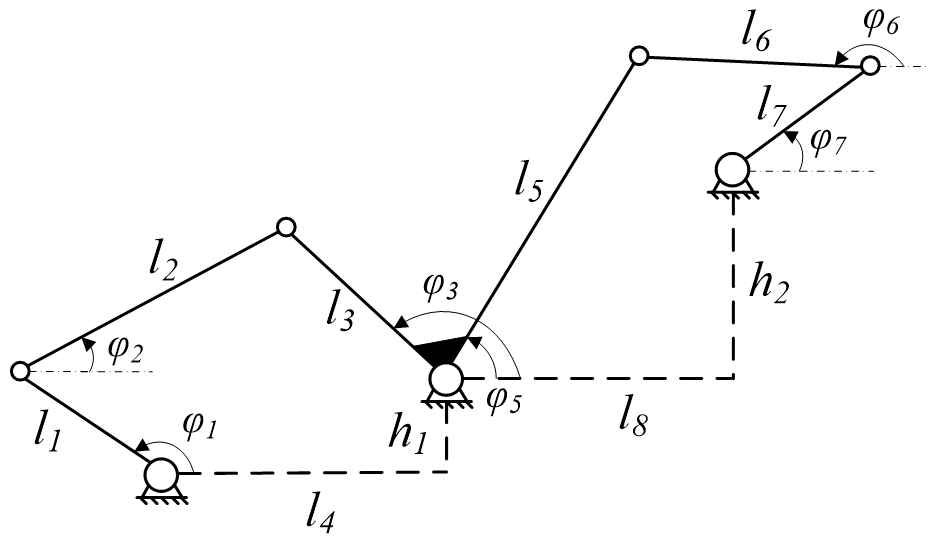
In an engineering project, the peripheral structure layout and allowable motion envelope size of the Watt-II six-bar mechanism are shown in Fig. 1. In the figure, l1, l2, l3, l5, l6 and l7 are the length dimensions of the bar members of the six-bar mechanism; φ1, φ2, φ3, φ5, φ6 and φ7, respectively, represent the angle between the corresponding bar members and the horizontal line; h1, h2, l4 and l8 are the vertical and horizontal dimensions between the hinges of the Watt-II six-bar mechanism. Rod l1 is connected with the output shaft of the driving mechanism, and the driving torque required for the movement of the six-bar mechanism is output, rod l3 is firmly connected with rod l5, rod l7 is the output rod of the mechanism, and angle φ7 is the output angle. Under the working condition, the rotation angular speed of the six-bar mechanism crank rod l1 is constant, and the load torque of the output rod l7 is 180 Nm; it is required that the mechanism crank rod l1 drives the mechanism to achieve the rotation angle range of the mechanism output rod l7 under the load condition of 120° while ensuring the stability of the mechanism motion.
2.2 Kinematic analysis of the mechanism
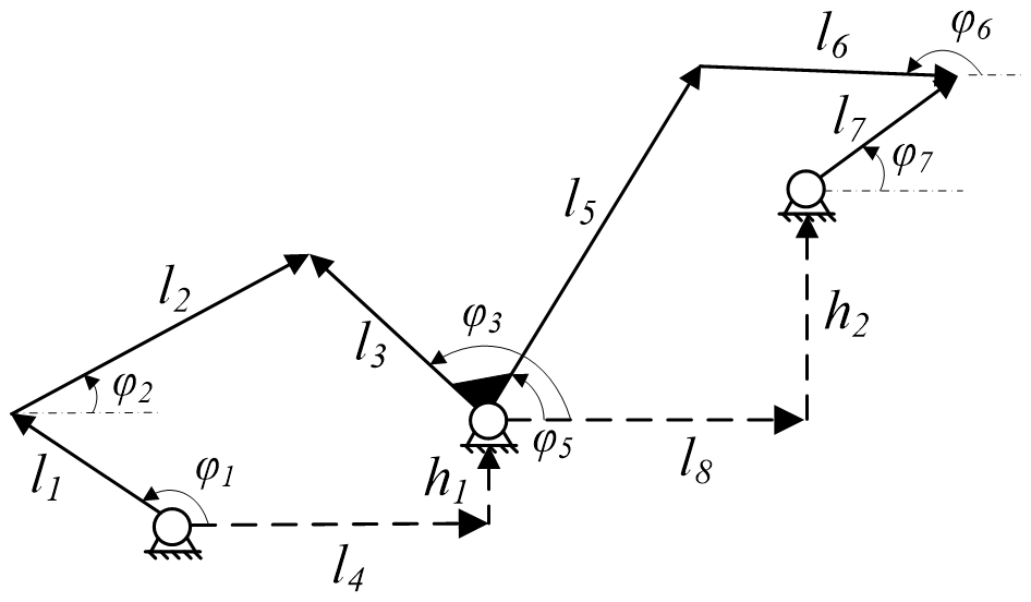
The mechanism rod in Fig. 1 is represented by a vector as shown in Fig. 2, and the vector equation can be obtained as follows:
By expressing the vectors in Eqs. (1) and (2) through complex numbers, the complex number equation can be obtained as follows:
In Eqs. (3) and (4), is the angle between each vector and the horizontal plane, where the fixed angles are
Since rod l3 and rod l5 are fixed, there is an angle relationship:
Combined with Euler's equation , Eqs. (3)–(5) can be further expressed as follows:
From Eq. (7), we obtain the following:
From Eq. (8), we obtain the following:
By combining Eqs. (7)–(10), the relation between the angles of the rods of the double four-link mechanism can be obtained:
2.3 Boundary condition
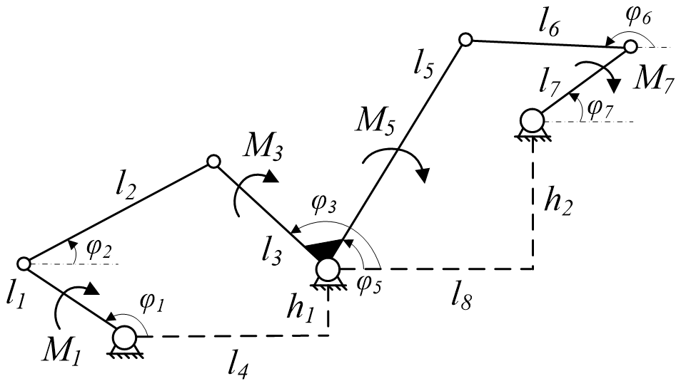
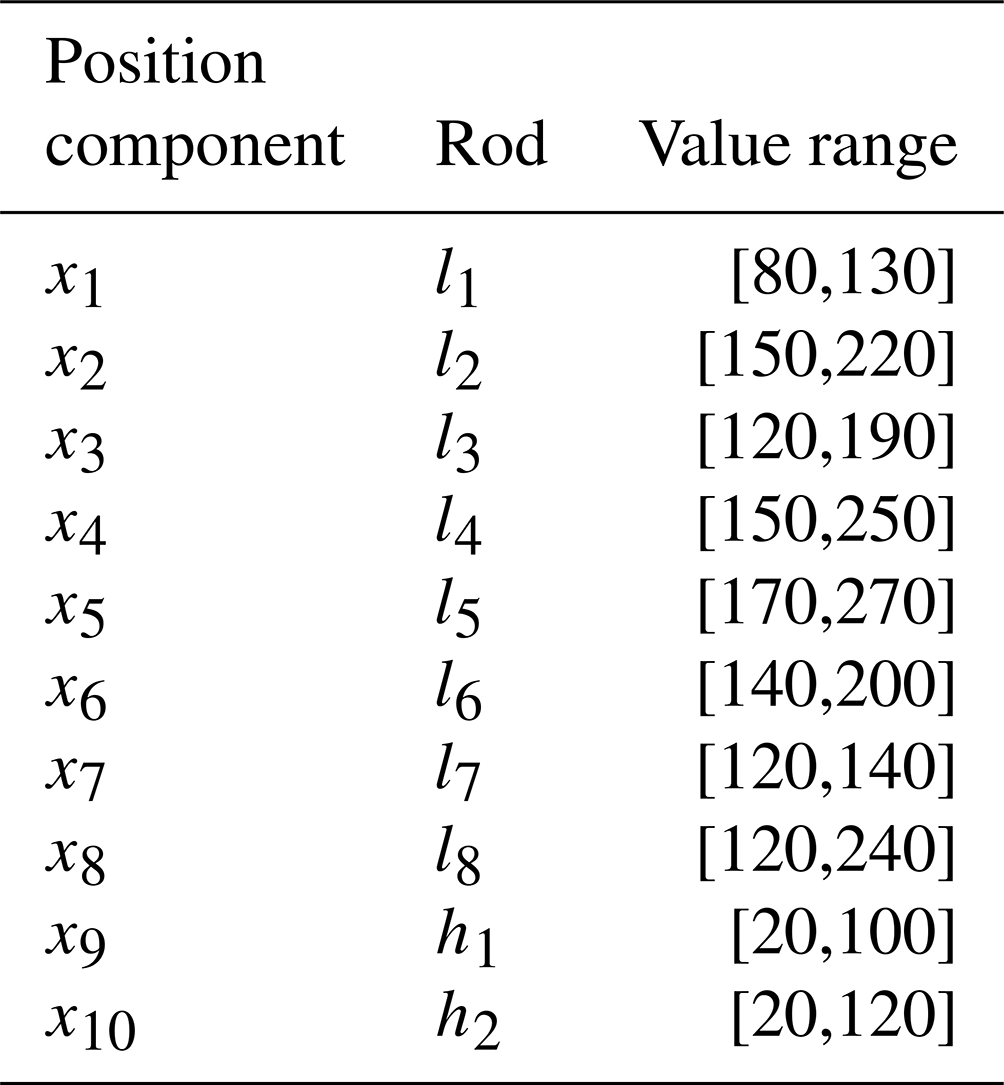
Considering the surrounding space size and motion envelope requirements of the Watt-II six-bar mechanism under this working condition, the given value range of each rod length is shown in Table 1.
According to Eqs. (7)–(14) and Table 1, the changes in angle and angular acceleration of each rod during the movement of the six-bar mechanism can be obtained when l1 motion characteristics of the crank rod are determined, which can be used as a reference for size optimization.
2.4 Mechanism dynamic analysis
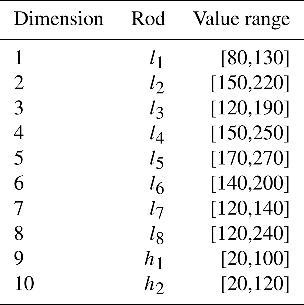
The force diagram of the Watt-II six-bar mechanism is shown in Fig. 3. In the figure, M1, M3, M5 and M7 are the torque subjected by the bar members l1, l3, l5 and l7, respectively.
The crank rod l1 is connected to the drive mechanism, the output fixed torque M1, and the force is transferred to rod l3 through the two-force rod l2. l3 torque of the rod can be obtained by the following calculation:
Rod l5 and rod l3 are fixed, so the torque of both is equal, M5=M3. Similarly, for the second part of the link, the force is transferred to rod l7 through the two-force rod l6. The l7 torque of the rod can be obtained by the following calculation:
By combining Eqs. (15) and (16), the relationship between output torque M7 and input torque M1 of the Watt-II six-bar mechanism can be obtained:
The bearing capacity of a mechanism is an important index to investigate the overall performance of that mechanism. The size of each rod in the Watt-II six-bar mechanism determines the output torque of the mechanism, so it is necessary to optimize the size of the mechanism and select the local optimal solution of each rod size within a certain range to improve the bearing capacity of the mechanism and ensure the working margin.
The particle swarm optimization (PSO) algorithm was first proposed by Kennedy and Eberhart (1995) to simulate the foraging process of birds. In the process of foraging, there is an individual closest to the food, which is the local optimal solution. The birds constantly adjust their position to get to this individual and at the same time try to make the group position optimal so as to obtain the global optimal solution.
Principle of the algorithm
In the particle swarm optimization algorithm, if the number of population individuals is k, the individual space dimension is d, and the number of iteration is m, then the population can be represented as .
The position of the ith particle is
The velocity of the ith particle is
where xid and vid represent the position and velocity of particle xi in the dth dimension, respectively.
The individual extremum of particle in the tth iteration is
The global extremum of the population in the tth iteration is
In the iterative process, the individual extreme value of the particles is obtained by updating the velocity and position to determine the individual optimal value, and the global extreme value is determined by the updated individual extreme value of the population. The equation for updating the velocity and position of particle in the tth iteration is
where pij(t) is the position component of the extreme value of the tth iteration of the ith particle in the jth dimension, and pgj(t) is the position component of the population of the tth iteration in the jth dimension, and xij(t) is the position component of the tth iteration of the ith particle in the jth dimension. c1 and c2 are the learning factors, c1 affects the amplitude of particle adjustment to the individual extreme value, c2 affects the amplitude of particle adjustment to the global extreme value. In order to prevent particles from exceeding the allowed range during iterative optimization, particle velocity and position are limited as follows:
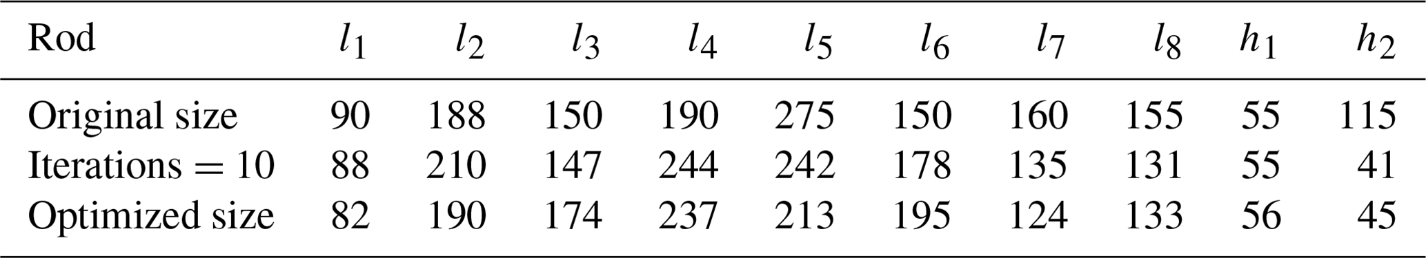
Table 5Size of the mechanism before and after size optimization.
4.1 Model building
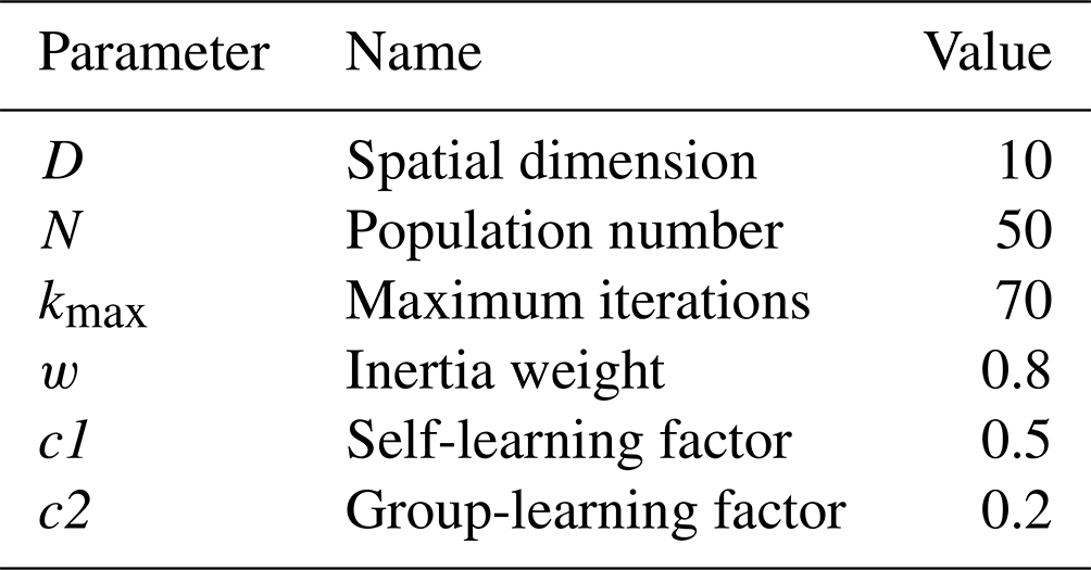
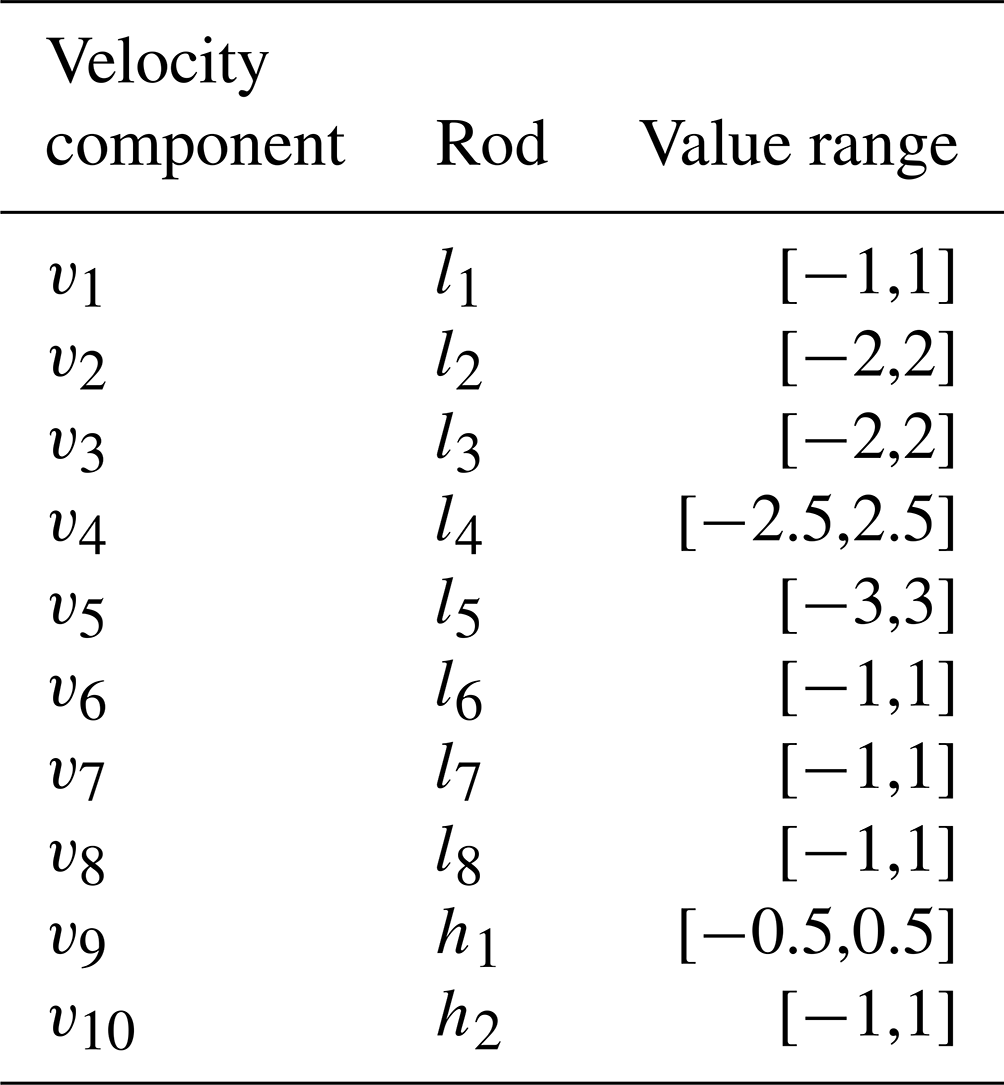
Combining the Watt-II six-bar mechanism and particle swarm optimization algorithm, the mathematical model of the size optimization of the Watt-II six-bar mechanism is established. It can be seen from Sect. 3 that the population in the particle swarm optimization algorithm is composed of multiple particle individuals, and different particles have different positions and velocity components in each dimension. In Fig. 1, the length of the member includes l1–l8, h1 and h2, all of which affect the output mechanical properties of the mechanism. The position component of a single particle in the population in each dimension corresponds to the length of each member of the mechanism and the spatial dimension of the population, d=10, and different member lengths correspond to different particles in the population. To ensure the stability of the algorithm, the number of particles in the population, N=50, is set. The initial parameter settings of the algorithm are shown in Table 2, the value ranges of particle position components in each direction are shown in Table 3, and the value ranges of velocity are shown in Table 4. In the constant load condition, the maximum output torque required by the mechanism is taken as the individual extreme value for each particle, and the global extreme value and the corresponding lengths of each link are obtained by traversing. The specific optimization process is described in Sect. 4.2.
4.2 Optimization process
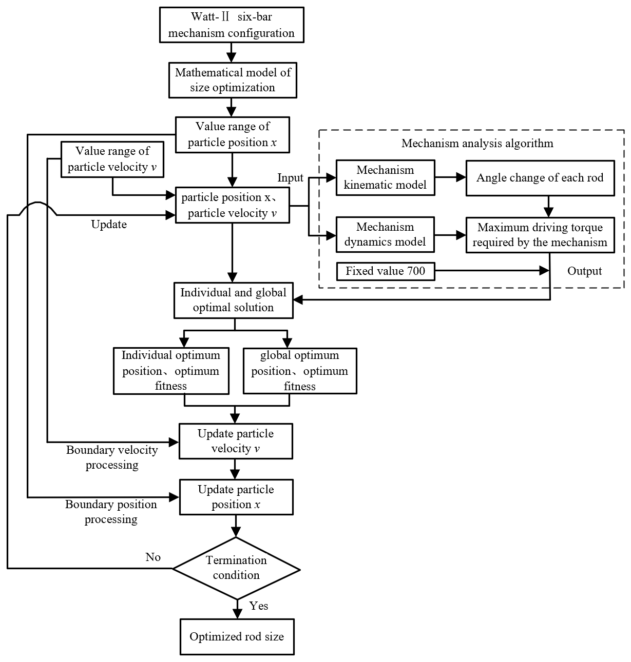
After the model is established, the size optimization algorithm is realized through MATLAB programming, and the specific process is shown in Fig. 4.
According to the basic configuration of the Watt-II six-bar mechanism, the mathematical model of size optimization is established with 10 dimensions corresponding to the components of the particle position in each direction in the particle swarm optimization algorithm. The value range of the mechanism size corresponds to the value range of the particle position x, and combined with the value range of particle velocity v, the initial position x and velocity v of each particle in the population are determined. The component of particle initial position x in each direction is the initial dimension of each lever of the mechanism. According to Eqs. (7)–(14), the kinematic model of the mechanism is built to determine the angle changes of each lever. Meanwhile, the dynamic model of the mechanism is built according to Eqs. (15)–(17), and the driving torque changes of the mechanism under a constant load condition are obtained by combining the angles of each lever. The maximum driving moment required for the work mechanism is selected as the individual and global extremum values of the particle swarm optimization algorithm are constantly increasing during the iterative optimization process, while the required maximum driving moment of the mechanism as the optimization goal should be constantly decreasing; therefore, the output of the mechanism analysis algorithm is obtained by subtracting the fixed value of 700 from the required maximum driving moment of the mechanism and then combined with the particle swarm optimization algorithm to calculate the individual extremum values of each particle in the population. The global extremum value is obtained by traversing the results.
The optimal position and fitness of the individual and the global are calculated by Eqs. (20)–(23) and combined with the value range of particle position x and velocity v, and the particle position x and velocity v are updated according to Eqs. (24) and (25). The global extreme value of this iteration (that is the output torque of the mechanism) is compared with the global extreme value of the last iteration. If the difference between the two is within the tolerance range, the loop is stopped. If the condition is not met, the updated particle position and velocity are used as the input of the mechanism analysis algorithm, and the loop continues until the condition is met. At the end of the cycle, the optimized connecting rod size is obtained. Under a constant load condition, the driving torque of the Watt-II six-bar mechanism with this size is minimal, and the size optimization effect is achieved.
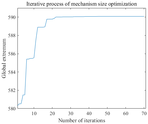
The change in the global extreme value in the iterative process of the algorithm is shown in Fig. 5. It can be seen that in the iterative process, the global extreme value keeps increasing and finally tends to be stable, which also indicates the process of continuous optimization of the population towards the optimal position.
4.3 Optimization result
The output motion characteristics and driving torque of the mechanism before optimization, during the optimization process (number of iterations =10) and after optimization are compared to verify the effect of size optimization.
The original design size and optimized size of the Watt-II six-bar mechanism are shown in Table 5.
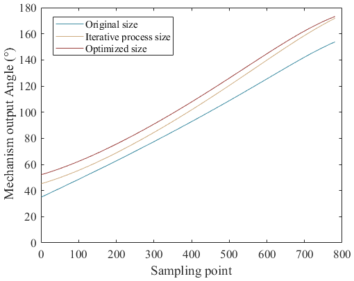
Under the same load conditions (same initial crank angle, same rotational angular speed and 180 Nm torque applied on output rod l7), the comparison between angle changes in output rod l7 during the motion process of the Watt-II six-bar mechanism before optimization, during the optimization process (number of iterations =10) and after optimization is shown in Fig. 6.
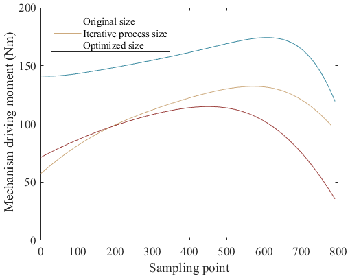
The comparison between the driving torque of each mechanism position (bending moment of crank rod l1) during the movement process is shown in Fig. 7.
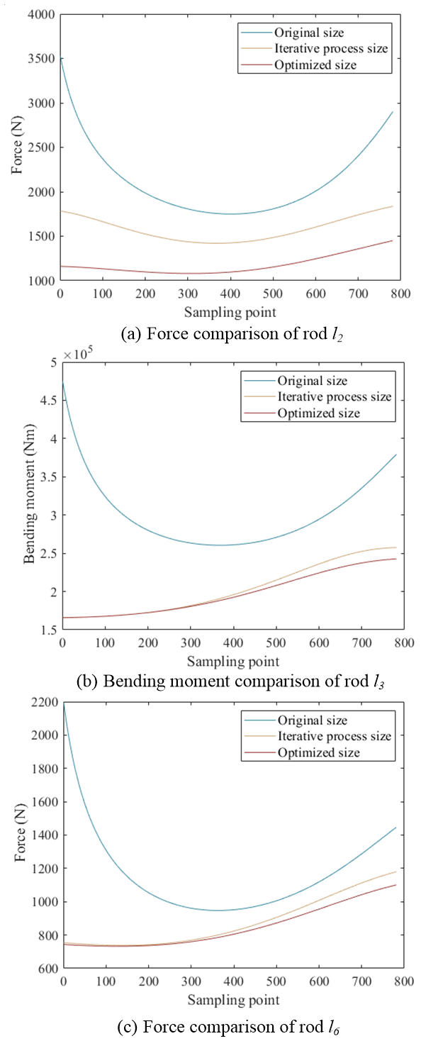
During the movement of the mechanism, the internal force of each rod is also an important factor to be considered. The comparison between the stress of each rod during the movement is shown in Fig. 8.
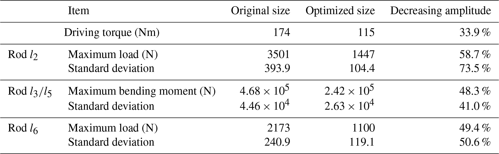
As can be seen in Fig. 6, the variation trend of the output angle curve of the original design size and the optimized size mechanism is basically the same, and the output angle range of the mechanism is basically the same, so the optimized size can ensure the motion stability of the mechanism. The driving torque required by the original design size and the optimized size mechanism and the stress situation of each rod during the movement of the mechanism are shown in Table 6.
After size optimization of the six-bar mechanism, under the same load, the driving torque and the stress of each rod are greatly reduced, the standard deviation of the stress change curve of the rod is smaller, and the stress change trend is stable. Size optimization can effectively improve the output capacity, operation efficiency and working margin of the mechanism. Under the premise of ensuring the safety factor and strength, the weight reduction optimization design of the parts of the mechanism can be done to improve the overall adaptability of the mechanism.
A kinematic and dynamic model of the Watt-II six-bar mechanism was established, and it was combined with the particle swarm optimization algorithm to establish a size optimization algorithm model for the Watt-II six-bar mechanism. The dimensions of the mechanism were optimized. After optimization, the mechanism's folding and unfolding angles and smoothness of motion were ensured while the driving torque was greatly reduced, thereby improving the mechanism's working ability. Although some progress has been made, there are still some shortcomings, and further improvements and more in-depth research can be made in the following areas:
-
More suitable and effective algorithms should be tested, and the exact and close relationship between the optimization algorithm and the mathematical model of the mechanism should be established, further improving the optimization effect and obtaining a more efficient mechanism size.
-
The algorithm model takes the required driving torque of the mechanism as the optimization goal, and then it can explore the optimization algorithm that takes into account the factors such as the smooth motion of the mechanism and the change trend of the internal stress of the member so as to improve the performance of the mechanism in all aspects.
In order to protect intellectual property rights and maintain the uniqueness of academic achievements, the software code can not be accessed.
All data used in this paper can be obtained upon request from the corresponding author.
HY, ZN and DH established the mathematical model of the Watt-II six-bar mechanism and designed the flow of size optimization algorithm. HY developed the model code. XS, WC, GT and TZ recorded the optimization process, sorted the data, and created the figures and tables. HY and ZN prepared the manuscript with contributions from all co-authors.
The contact author has declared that none of the authors has any competing interests.
Publisher's note: Copernicus Publications remains neutral with regard to jurisdictional claims made in the text, published maps, institutional affiliations, or any other geographical representation in this paper. While Copernicus Publications makes every effort to include appropriate place names, the final responsibility lies with the authors.
This paper was edited by Med Amine Laribi and reviewed by two anonymous referees.
Chen, Y.-S.: Optimal Design of crank and Rocker Mechanism based on DFM [J], Mechanical design and manufacturing, 2012, 2, https://doi.org/10.3969/j.issn.1001-3997.2012.10.014, 2012.
Dong, E., Xu, M., Li, Y., and Yang, J.: Optimization of synchronization performance of single crank and double rocker mechanism [J], J. Mech. Eng., 2010, 5, https://doi.org/10.3901/JME.2010.07.022, 2010.
Fang, D., Zhang, C., and Cao, X.: Application of Planar Linkage Mechanism in Automatic Flat Press [J], Mech. Res. Appl., 2004, 28–29, 2004.
Kennedy, J. and Eberhart, R.: Particle swarm optimization [C], IEEE International Conference on Neural Networks, 1995, Proceedings, 1995, 1942–1948, 1995.
Li, J. and Xiong, H.: Improved Genetic Algorithm for Scaling Optimization of Six-Bar Mechanism with Dead Center Position [J], Modular Mach. Tool Auto. Mach. Technol., 2022, 5, https://doi.org/10.13462/j.cnki.mmtamt.2022.03.008, 2022.
Li, X., Zhang, L., and Wei, S.: Algebraic Solution for Trajectory Synthesis of Stephenson-III Planar Six-bar Mechanism [J], Eng. Sci. Technol., 2021, 53, 7, https://doi.org/10.15961/j.jsuese.201901183, 2021.
Ma, J. and Chen, T.: Optimization of Series Four-link Mechanism Based on Genetic Algorithm and Nonlinear Programming [J], Journal of Chengdu University: Natural Science Edition, 41, 83–88, 2022.
Song, Z., Luo, Z., and Xie, H.: Design and obstacle-crossing analysis of a four-link rocker-suspension planetary exploration robot, Mech. Sci., 15, 137–157, https://doi.org/10.5194/ms-15-137-2024, 2024.
Sun, W., Kong, J., and Sun, L.: A holographic matrix representation of the metamorphic parallel mechanisms, Mech. Sci., 10, 437–447, https://doi.org/10.5194/ms-10-437-2019, 2019.
Sun, Y., Zhou, J., Gong, D., and Ji, Y.: Study on multi-degree of freedom dynamic vibration absorber of the car body of high-speed trains, Mech. Sci., 13, 239–256, https://doi.org/10.5194/ms-13-239-2022, 2022.
Tan, M.: Application of Planar Connecting Rod Mechanism in Plate Shearing Machine [J], Metal Working (Hot Working), 09, 57, 2011.
Tian, D., Gao, H., Jin, L., Liu, R., Zhang, Y., Shi, C., and Xu, J.: Design and kinematic analysis of a multifold rib modular deployable antenna mechanism, Mech. Sci., 13, 519–533, https://doi.org/10.5194/ms-13-519-2022, 2022.
Tuleshov, A., Halicioglu, R., Shadymanova, A., and Kuatova, M.: Kinematic synthesis method and eccentricity effects of a Stephenson mechanism, Mech. Sci., 12, 1–8, https://doi.org/10.5194/ms-12-1-2021, 2021.
Wang, J., Niu, K., Nie, L., He, H., Chen, Z., Wang, Q., and Ren, J.: Singularity Analysis of Complex Planar Linkage with Single Degrees of Freedom [J], China Mechan. Eng., 29, 36–40, 2018.
Wang, L., Jiang, L., and Wang, Y.: Four-bar mechanism optimization based on genetic quasi-Newtonian hybrid algorithm [J], Journal of Hefei University of Technology: Natural Science Edition, 41, 4, https://doi.org/10.3969/j.issn.1003-5060.2018.02.002, 2018.