the Creative Commons Attribution 4.0 License.
the Creative Commons Attribution 4.0 License.
 | 16 Apr 2025
Research on fuzzy proportional–integral–derivative (PID) control of bolt tightening torque based on particle swarm optimization (PSO)
Xiao Cheng
Zhanghao Guo
Jun Ke
Bolt connections are common in industrial and manufacturing applications; however, improper torque tightening can lead to issues such as over-tightening or under-tightening, which negatively affect connection quality and lifespan. To enhance the precision of bolt tightening, this paper introduces a particle swarm optimization (PSO) algorithm to optimize a fuzzy proportional–integral–derivative (FPID) controller. Effective methods for adjusting the parameters of the PSO and FPID control systems are also explored to improve the control performance while ensuring stability and reliability under complex load conditions. Simulations were conducted using MATLAB Simulink to compare the tightening speeds of the PSO-optimized FPID controller, the PSO-optimized PID controller, the traditional FPID controller, and the PID controller. Results indicate that the PSO-optimized FPID controller significantly improves the response speed, reduces overshoot, and enhances the system's adaptability and robustness. In experiments targeting a torque of 12 N m, the average deviation is 0.108 N m, achieving a control accuracy of 0.9 %. These findings validate the effectiveness of the proposed control system and demonstrate a marked improvement in the precision of bolt tightening. Overall, this research highlights the potential of integrating PSO into FPID control to enhance the bolt connection quality and reliability, addressing a critical aspect of industrial fastening.
- Article
(3155 KB) - Full-text XML
- BibTeX
- EndNote


With the continuous advancement of industrial technology and the development of the manufacturing industry, the requirements for bolt tightening have become increasingly stringent. The industrial sector's demands for assembly quality, speed, and cost efficiency drive the in-depth research and improvement of bolt tightening technology (Hu et al., 2020; Shi et al., 2024). In fields such as automotive, aerospace, and electronic equipment, the quality of bolt tightening directly impacts the safety and reliability of products (Yang et al., 2023). Consequently, bolt tightening technology has gradually become a crucial technology in mechanical assembly (Nah and Choi, 2018).
Traditional methods for bolt connection control primarily include the torque method, torque–angle method, yield point method, and elongation method (Matsumura et al., 1995; Shoberg, 2000; Tsuji and Maruyama, 1999). Each of these methods has certain limitations that prevents it from meeting the requirements of high precision, low cost, and high material utilization (Zhan et al., 2013; He et al., 2014).
In the late 20th century, proportional–integral–derivative (PID) control was widely adopted to address the challenges of bolt tightening torque control (Chang, 2015; Merrikh-Bayat et al., 2015; Yao et al., 2024). However, in the face of complex multivariable, nonlinear, and time-varying characteristics, parameter tuning often leads to poor control performance (Ahmadnia et al., 2024; Geng et al., 2022; Jia et al., 2023). To achieve precise bolt tightening control, many researchers have combined modern control technologies with traditional torque control methods (Dhayagude et al., 1996; Jia et al., 2019). Wu et al. (2020b) designed an adaptive-gain second-order sliding-mode controller (SMC) to overcome nonlinearity and uncertainty, ignoring the fact that the SMC may face chattering and sensitivity to model errors. The model-free fuzzy logic controller (FLC) developed by Deters et al. (2013, 2015) achieves precise control by regulating the tightening angle, but its optimization capabilities are limited. Wu et al. (2020a) further improved the torque control by combining the FLC with the torque–angle method, reducing the need for accurate modeling and enhancing the performance under varying conditions. Althoefer et al. (2008) and Liu et al. (2020) applied neural networks together with FLC to predict bolt tightening outcomes. Liu et al. (2016) designed an adaptive recursive controller based on a fuzzy system. Using a gray model for fuzzy PID (FPID) control, Zhang and Xiao (2024) proposed a nonlinear control system that outperformed traditional FPID systems. Although PID controllers generally outperform FLC and basic PID controllers in controlling nonlinear systems, the actual implementation of FPID control requires complex adjustment of the PID parameters within the FPID controller (An et al., 2023; Boudia et al., 2021). This process increases the difficulty of system design and debugging, thus introducing subjectivity and uncertainty (Hermassi et al., 2024).
Many scholars have integrated modern control technology with artificial intelligence (AI) to tackle the challenges of parameter adjustment and subjectivity (Alenizi et al., 2023; Li et al., 2024; Wang et al., 2022). For instance, Hasan et al. (2023) optimized the initial weights of a neural network PID controller by combining particle swarm optimization (PSO) and genetic algorithms to manage voltage fluctuations in microgrids. Altbawi et al. (2024) improved the tuning of fractional-order PID controllers using a gradient-based optimization algorithm to enhance system robustness. Gün (2023) developed a PID controller employing differential evolution for the low-energy positioning control of quadrotors. Manuel et al. (2023) evaluated various optimization algorithms for PID controllers and found that teaching–learning-based optimization (TLBO) was the fastest in identifying optimal values, followed closely by PSO.
In bolt tightening, the PSO-optimized FPID controller improved stability and robustness by handling nonlinear, time-varying dynamics(Muftah et al., 2022). By adjusting its parameters dynamically, the controller maintains the performance despite fluctuations in friction and elasticity, ensuring reliable control without needing an accurate system model (Štimac et al., 2014; Sun et al., 2022).
In addition, finite-element analysis (FEA) is commonly used to examine stress distribution, deformation, and friction in bolts under different tightening conditions (Feng et al., 2023; Zheng et al., 2025). However, FEA's high computational cost and reliance on linear assumptions limit its practical use for precise torque control in bolt tightening (Chen et al., 2023; Gür and Cen, 2024). Overall, while AI-enhanced control methods are being increasingly applied, research combining traditional control strategies with AI remains limited.
This study employs the torque–angle method to translate the precise control of tightening torque into speed control for a servo motor, effectively addressing the nonlinearity and uncertainty caused by material properties, friction coefficients, and manufacturing precision. We designed a PSO-optimized FPID control system to tackle nonlinear issues arising from inertia, mechanical vibrations, and friction during the servo motor's startup, deceleration, and stopping phases. Precise control over nonlinear dynamics can be achieved by optimizing the controller parameters and integrating the FLC. The combination of PSO and the FPID controller enhances the system's dynamic performance and control accuracy, improving robustness and adaptability while maintaining low sensitivity to the model and practical conditions. This innovative approach offers new perspectives and methods for control systems with broad application potential.
The remainder of this paper focuses on the following: establishing a mathematical model for bolt connections, analyzing the tightening mechanism's speed, and developing a corresponding control model. We propose a control strategy that combines PSO with an FPID controller for simulation experiments. The study concludes with a summary of the research findings.
A mathematical model that can accurately describe the behavior and characteristics of a system must be established to provide a theoretical foundation for system analysis, design, and control. Through this mathematical model, the internal mechanisms of the system can be deeply understood, the system behavior can be predicted, and the engineering efficiency and reliability can be improved (Liu et al., 2022a). Therefore, developing a mathematical model for the bolt connection is essential.
During the bolt connection, the bolt is subjected to preload and working tensile forces, which is the most common form of bolt connection (Jiang et al., 2022). Deformation occurs when the bolt experiences axial force and working load, causing the total tensile force on the bolt to differ from the sum of the preload and working tensile force. The force analysis of the bolt is depicted in Fig. 1.
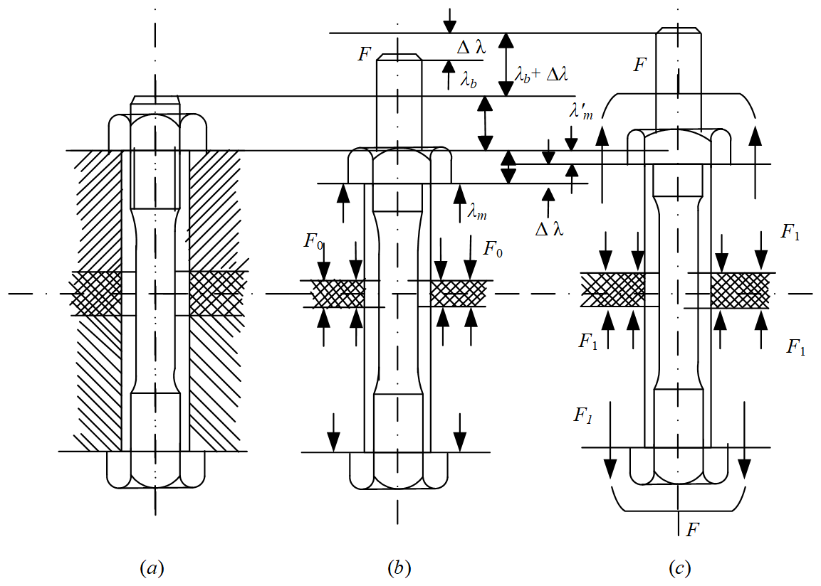
Figure 1Force diagram of the bolt connection: (a) loose nut, (b) tightened nut, and (c) bare working load.
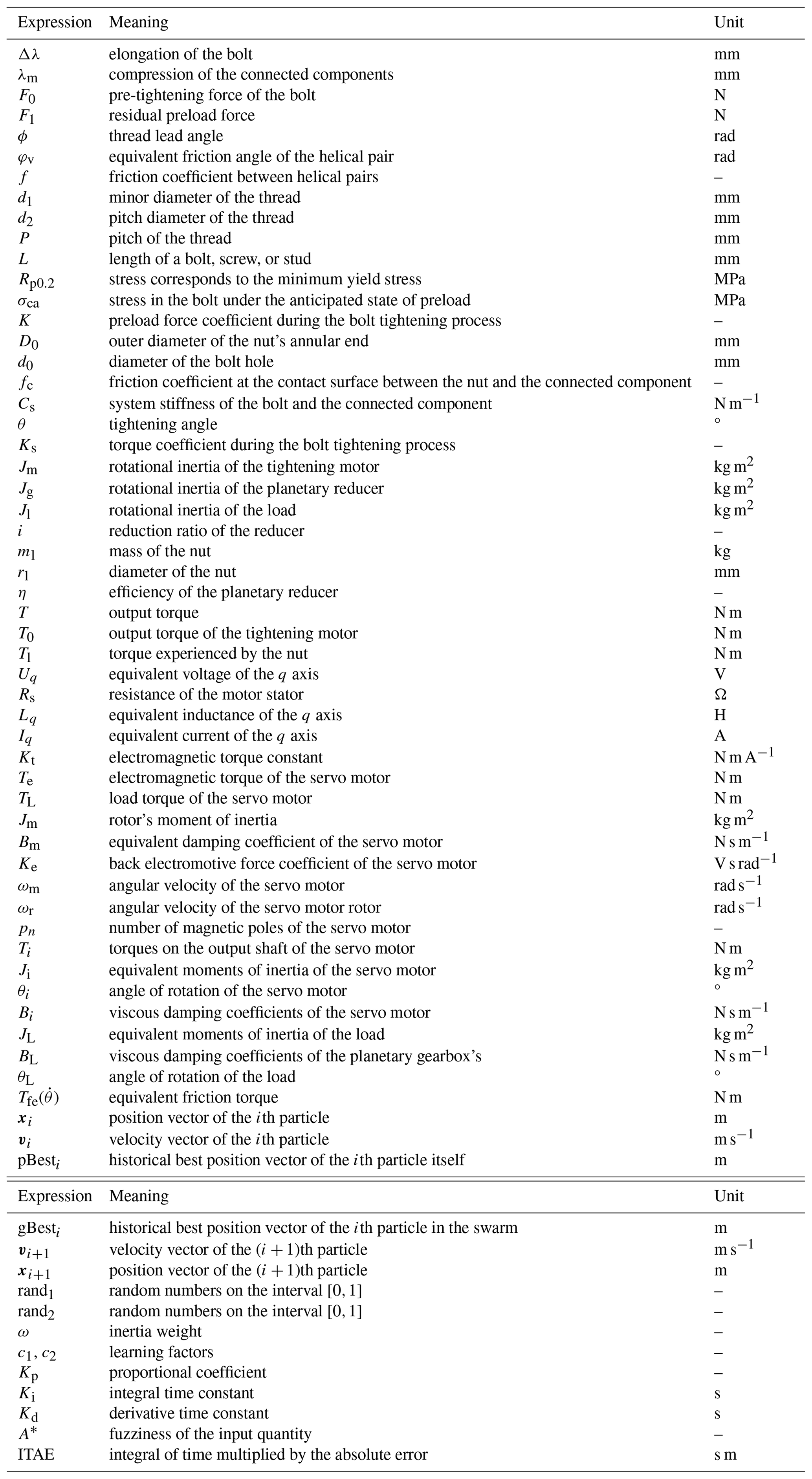
In Fig. 1, Δλ represents the elongation of the bolt, with the total elongation denoted by Δλ−λb, and λm represents the compression of the connected components, with the total compression denoted by . F represents the working tension of the bolt. F0 represents the preload force applied to the bolt, and F1 represents the residual preload force. The variables and definitions for each formula are shown in Table 1.
2.1 Analysis of bolt connection strength and preload force
During the assembly process, excessive preload on the bolt can adversely affect the assembly quality and, in severe cases, lead to bolt fracture and unpredictable consequences. Therefore, it is necessary to perform strength calculations for the bolt connection (Lin et al., 2021). The tensile stress (σ) and torsional shear stress (τ) on bolts in a plastic state are given by
where ϕ represents the thread lead angle, φv denotes the equivalent friction angle of the helical pair, f signifies the friction coefficient between helical pairs, d1 stands for the minor diameter of the thread, d2 represents the pitch diameter of the thread, and P denotes the pitch.
According to the fourth strength theory (Liu et al., 2022b), which is as follows:
when the length of a bolt, screw, or stud is L≥2.5d, the plastic elongation of the bolt reaches 0.2 %, and the stress corresponds to the minimum yield stress point Rp0.2 of the bolt (Noble, 2013).
where σca represents the stress in the bolt under the anticipated state of preload.
From Eq. (5), the preload force F acting on the bolt due to combined tension and torsion can be obtained as follows:
According to Eq. (6), the preload force acting on the bolt is closely related to the friction coefficient between the helical pairs.
2.2 Mathematical analysis of the torque–angle model
The tightening torque T of the bolt is the sum of the thread friction torque (Tth) between the bolt and the nut and the friction torque (Tb) between the nut and the contact surface of the connected components.
Eqs. (8)–(9) result in the following:
where K is the preload force coefficient during the bolt tightening process, D0 is the outer diameter of the nut's annular end, d0 is the diameter of the bolt hole, and fc is the friction coefficient at the contact surface between the nut and the connected component.
According to the above equation, the main factors affecting the tightening torque of the bolt are the friction coefficient f between the helical pairs and the friction coefficient fc between the nut and the contact surface of the connected component.
The use of the torque–angle method to control bolt tightening effectively reduces the impact of the two friction coefficients on the tightening process. The tightening process can be divided into four stages: the contact stage, snug stage, elastic linear stage, and plastic yielding stage. This process involves three variables: tightening torque, preload force, and tightening angle (Fig. 2).
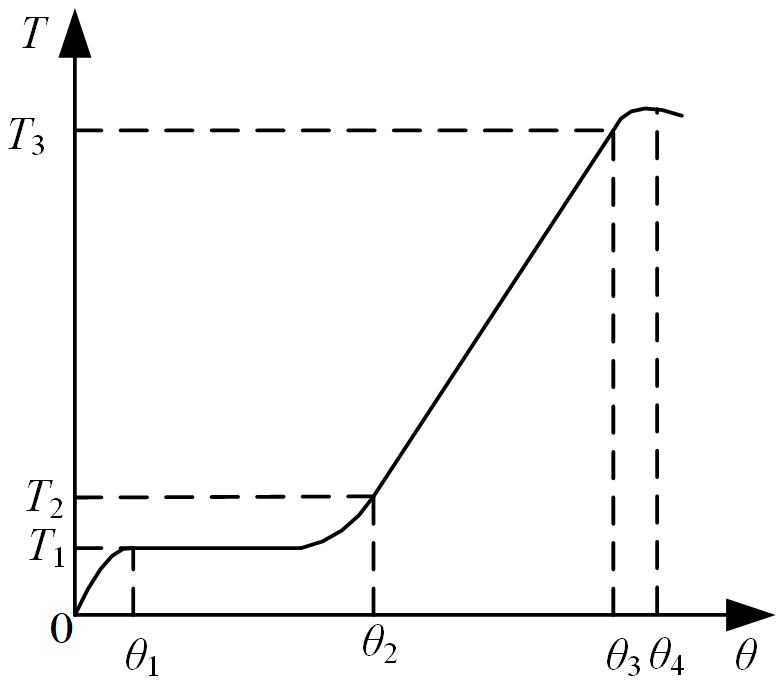
Figure 2Schematic illustrating the relationship between the bolt tightening torque and angle.
In Fig. 2, T1 represents the torque when the bolt contacts the nut, T2 denotes the snug torque when the bolt (or nut) contacts the connected component, and T3 signifies the tightening torque when the bolt (or nut) and the connected component are being tightened. From practical engineering, it is known that the snug torque T2≈0.25T3. In the elastic region, the relationship between preload force and rotation angle is given by Eq. (12):
where is the system stiffness of the bolt and the connected component and θ represents the angle of rotation of the bolt or nut, namely, the tightening angle. The preload force (F0) of the bolt is directly proportional to the angle of rotation of the bolt (or nut).
The relationship between bolt tightening torque and tightening angle, derived from Eqs. (11)–(12), is described by the following:
where Ks is the torque coefficient during the bolt tightening.
In the mathematical modeling analysis of the torque–angle method, the relationship between the tightening torque and angle is proportional within the elastic region of the bolt. Therefore, the precise control of the bolt tightening torque can be considered the precise control of the bolt tightening angle. The bolt tightening angle θ is related to the speed ω and the rotation time t of the tightening mechanism. Therefore, research on the control of the bolt tightening torque can be viewed as research on the control of the motor speed in the tightening mechanism.
3.1 Modeling and analysis of the tightening mechanism's speed curve
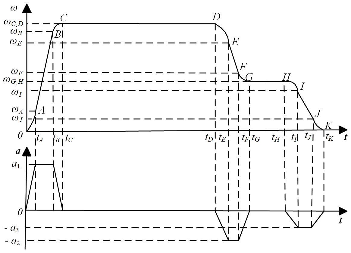
Building upon the torque–angle method, this work divides the bolt tightening process into three stages: the contact stage, snug stage, and tightening stage. Torque calculation and analysis are conducted for each stage, and the tightening speed is designed by considering the working efficiency and control precision during the actual tightening. The principles of segment by segment and speed by speed are adopted to control the tightening mechanism's speed. An S-shaped velocity curve with smooth velocity variation and minimal impact vibration, characterized by a trapezoidal acceleration curve, is selected for the velocity planning of the tightening mechanism (Fang et al., 2020).
In Fig. 3, segment OC represents the capping stage during the bolt tightening, indicating complete contact between the nut and the bolt. At this point, the torque is relatively low, and the motor operates at its rated speed. Segment DG represents the snugging stage, where the snug torque is achieved, followed by the elastic stage (HK segment), where linear tightening occurs. At point K, the motor speed is zero, and the torque reaches the plastic yield stage without causing damage to the bolt. The effective moment of inertia after the planetary reducer, denoted as Jeff, is calculated as follows:
where Jm, Jg, and Jl, respectively, represent the rotational inertia of the tightening motor, the rotational inertia of the planetary reducer, and the rotational inertia of the load. i represents the reduction ratio of the reducer. Assuming that the rotational inertia of the load does not change with variations in speed and torque, and using ml and rl to represent the mass and diameter of the nut, respectively, Eq. (16) can be derived as follows:
In calculating the acceleration of the tightening motor under load, the efficiency η of the planetary reducer needs to be considered. The output torque T is
The output torque (Tm) is the rated torque of the motor. Using Eqs. (15)–(17) and Newton's second law, the formula for the acceleration of the motor under load can be derived as follows:
where T0 is the output torque of the tightening motor and Tl is the torque experienced by the nut.
3.2 Modeling and analysis of the power system
The tightening mechanism can be divided into the power and transmission systems. The former primarily consists of the motor, and the latter comprises the reducer and linkage components. This study employs an AC servo motor due to its compact size, long lifespan, fast computational speed, and robust control capabilities. The AC servo motor, consisting of a stator and a rotor, is controlled through the position, speed, and current loops. For effective control of the AC servo motor, its mathematical model must be simplified in a manner that does not significantly affect the results. Given the inherent nonlinear behavior of the motor, certain assumptions must be made about the motor (Gao et al., 2012; Hou et al., 2017).
-
The hysteresis phenomenon of magnetic flux and eddy current losses are not considered.
-
The counter-electromotive force generated by the permanent magnet is uniformly distributed according to a certain pattern.
-
The leakage of the magnetic flux from the motor windings and the excessive saturation of the iron core are ignored.
-
Damping on the permanent magnet is not taken into account, and the absence of damping windings on the rotor is assumed.
In Fig. 4, Uq represents the equivalent voltage of the q axis, Rs represents the resistance of the motor stator, Lq is the equivalent inductance of the q axis, Iq represents the equivalent current of the q axis, Kt denotes the electromagnetic torque constant, Te represents the electromagnetic torque of the servo motor, TL is the load torque of the servo motor, Jm represents the rotor's moment of inertia, Bm is the equivalent damping coefficient of the servo motor, Ke is the back electromotive force coefficient of the servo motor, and ωm is the angular velocity of the servo motor.
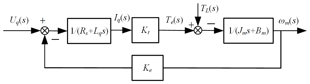
In the d–q coordinate system, the voltage equations for the servo motor are given by Eqs. (19)–(20):
where ωr is the angular velocity of the servo motor rotor. The relationship between the servo rotor angular velocity and the mechanical angular velocity (ωm) of the servo motor is given by Eq. (21):
where pn is the number of magnetic poles of the servo motor.
To ensure that the magnetic field vector of the servo motor rotor is orthogonal to the armature current vector, making Id=0, the equation for the electromagnetic torque (Te) at this point is given by Eq. (22):
The balance equation for voltage and current in the servo motor is given by
Combining Eqs. (22)–(24), the control equation for the servo motor is given by Eq. (25).
3.3 Transmission system modeling and analysis
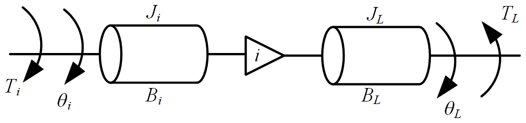
The transmission system in the tightening mechanism utilizes a planetary gearbox to reduce the speed of the servo motor and increase the torque output. Its mathematical model can be represented using an elastic system model (Liu et al., 2015).
Figure 5 shows the simplified model of the planetary gearbox, with the torque balance equations for its input and output shafts given by Eqs. (26)–(27).
where Ti and TL are the torques of the output shaft of the servo motor and the load, respectively; Ji and JL are the equivalent moments of inertia of the servo motor and the load, respectively; θi is the angle of rotation of the servo motor; Bi and BL are the viscous damping coefficients of the servo motor and the planetary gearbox's driven wheel, respectively; T is the equivalent torque acting on the gear train of the planetary gearbox; i is the reduction ratio of the planetary gearbox; and θL is the angle of rotation of the load.
By substituting into Eq. (27) and combining it with Eq. (26), Eq. (28) can be obtained.
From Eq. (28), Eqs. (29)–(31) can be derived.
where Je is the equivalent moment of inertia and Be is the damping coefficient. The equivalent mathematical model of the transmission system can be obtained from Eqs. (26)–(31).
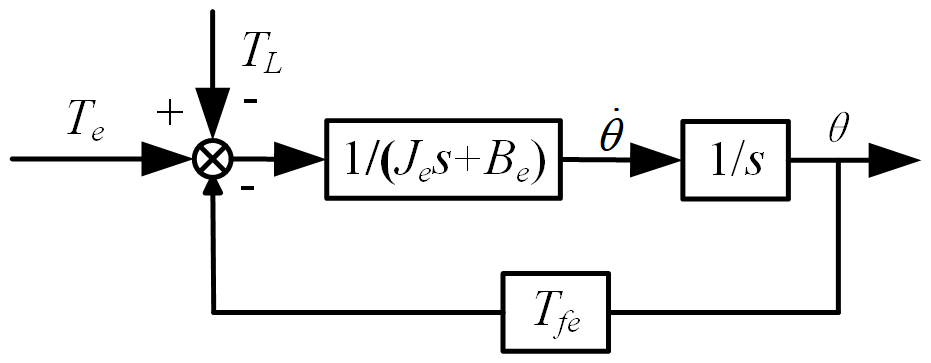
where Te is the equivalent output torque of the transmission system, θ is the rotation angle of the output shaft of the transmission system, TL is the torque of the load, is the equivalent friction torque, and de is the equivalent error.
Under practical application conditions, Be, Bm, and are small enough to ignore the equivalent friction torque , equivalent damping coefficient Be, and equivalent viscous damping coefficient Bm of the servo motor to simplify the model, as shown in Fig. 6.
Traditional PID tuning methods, such as engineering estimates and trial and error, often face limitations due to subjective influence and restricted applicability (Hagiwara et al., 2013). This study uses the PSO algorithm to enhance PID tuning, leveraging its global search ability, efficiency, simplicity, and adaptability to find optimal PID parameters (Charkoutsis and Kara-Mohamed, 2023; Kashyap and Parhi, 2021). Integrating PSO into an FPID controller improves control accuracy and responsiveness by enabling real-time parameter adjustment, bridging the gap between model predictions and real-world conditions and adapting effectively to variable operational demands (Muftah et al., 2023; Shao et al., 2022).
4.1 PSO algorithm
The PSO algorithm is renowned for its excellent global search strategy and simple operational model, making it highly effective in optimizing PID controller parameters and thereby enhancing system control performance (Liu et al., 2021; Song et al., 2021). This algorithm is a type of swarm intelligence optimization technique that mimics the behavior of bird flocks or fish schools, where each particle adjusts its position and velocity in the solution space based on its own experience and collaborative information from the group to find the optimal solution. Each particle has a position vector, which represents the candidate solution's location, and a velocity vector, which indicates the particle's movement direction and speed within the solution space (Song et al., 2022).
Figure 7 illustrates the relationship between the velocity and position of particles in the 2D space of the PSO algorithm and presents a diagram of the updates. In the figure, xi represents the position vector of the ith particle, vi is the velocity vector of the ith particle, pBesti denotes the historical best position vector of the ith particle itself, and gBesti represents the historical best position vector of the ith particle in the swarm. The corresponding equations are shown below, in Eqs. (33)–(34):
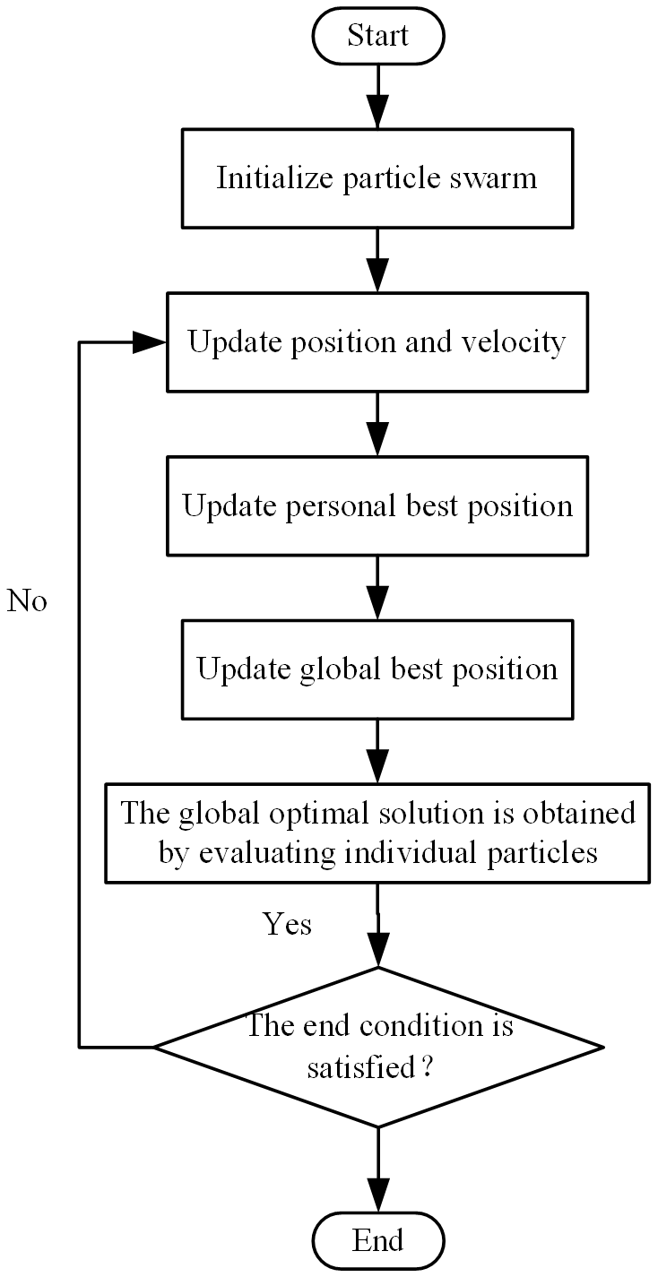
where vi+1 is the velocity vector of the (i+1)th particle, xi+1 is the position vector of the (i+1)th particle, rand1 and rand2 are random numbers on the interval [0,1], ω is the inertia weight, and c1 and c2 are the learning factors. The flowchart of the particle swarm optimization algorithm is illustrated in Fig. 8.
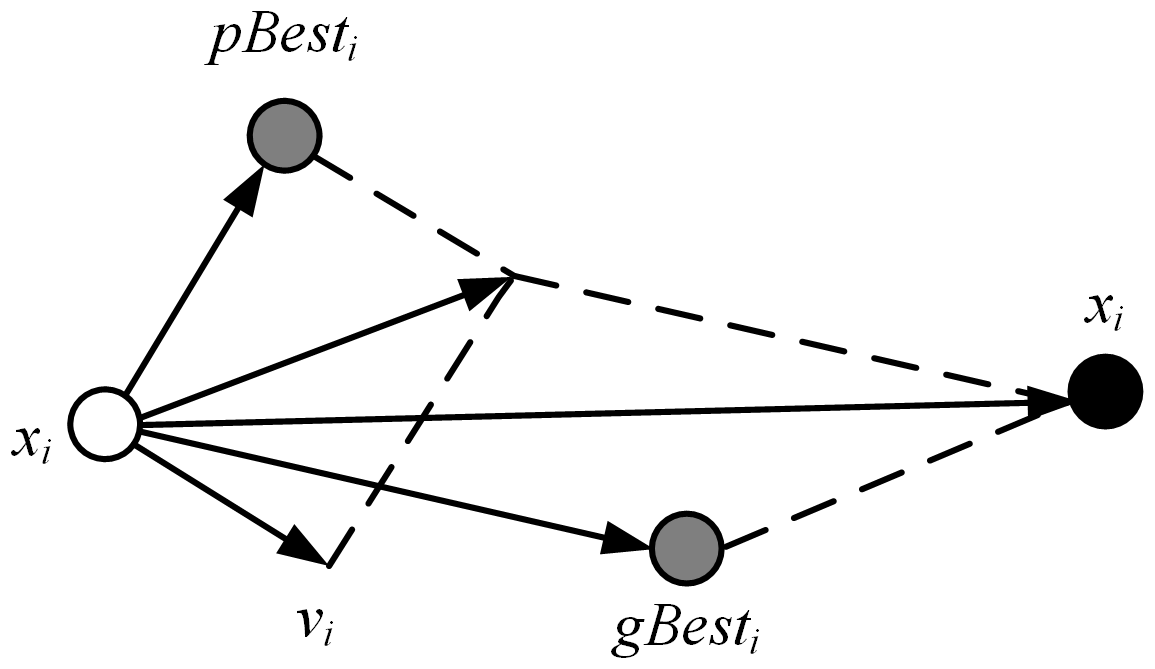
Figure 7Relationship between the velocity and position of particles in a 2D space and their update process in PSO.
4.2 FPID controller
The FPID controller combines fuzzy sets and fuzzy rules from fuzzy logic with the traditional PID controller, transforming precise values into fuzzy outputs through fuzzification and fuzzy inference and obtaining PID control outputs through defuzzification. The FPID controller adjusts the three input parameters of the PID controller in real time based on the error (the difference between the desired value and the output value) and its rate of change, thereby achieving control of the target.
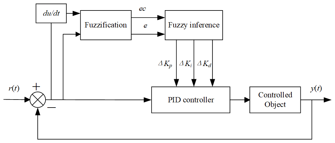
Figure 9 depicts the structural diagram of the FPID controller, where r(t) represents the set point; y(t) represents the actual output value; and e represents the error between them, . ec represents the rate of change in the error; ΔKp, ΔKi, and ΔKd are the control parameters for the fuzzy control output.
According to the control requirements, a positional PID controller is adopted (Liu and Chen, 2023) and expressed as in Eq. (35):
where Kp, Ki, and Kd represent the proportional coefficient, integral time constant, and derivative time constant, respectively.
Fuzzification is the process of transforming real values of input variables into linguistic variable values within the basic domain. This is achieved through membership functions, and the selection of appropriate membership functions is crucial. Triangular membership functions are particularly advantageous due to their mathematical simplicity, strong adjustability, and adaptability (Xie et al., 2023). Their form is shown in Eq. (36).
In fuzzy control systems, if–then expressions are commonly used to represent fuzzy rules. This form of rules has the advantages of being easy to understand and implement, flexible, intuitive, and computationally efficient. If each fuzzy statement provides a fuzzy mapping relationship (denoted as Ri) and the number of fuzzy relationships is n, then the overall fuzzy mapping relationship of the entire system is given by Eq. (37):
After fuzzy inference, the fuzzy quantity of the system output is
where A∗ represents the fuzziness of the input quantity.
Defuzzification is the process of obtaining a precise value that best represents the content of the fuzzy set obtained through reasoning. There are mainly three methods for defuzzification: the maximum membership principle, the centroid method, and the weighted average method. Among them, the centroid method simplifies the calculation process, improves computational efficiency, ensures the stability and robustness of the control system, and is suitable for practical applications of various control problems. The algebraic form of the centroid method is given by Eq. (39):
4.3 Simulation experiment of the PSO-optimized FPID controller
This study employs the PSO algorithm to optimize the parameters of the PID controller combined with FLC to generate a FPID controller for controlling the speed error of the AC servo motor. Seven fuzzy variables, NB, NM, NS, Z0, PS, PM, PB, respectively, represent negative large, negative medium, negative small, zero, positive small, positive medium, and positive large. Forty-nine fuzzy rules are designed (Zhang et al., 2021). The specific fuzzy control rules are as follows:
-
When the error is large, to reduce the error and prevent integral saturation, a larger ΔKp, a moderate ΔKd, and a smaller ΔKi can be set.
-
When the error is moderate, to reduce overshoot and error, smaller or moderate values for ΔKp and ΔKd and a smaller value for ΔKi should be selected.
-
When the error is small, to enhance system stability, larger values for ΔKp and ΔKi and a smaller value for ΔKd can be selected.
-
When is large and increasing, to reduce the error, larger values for ΔKp and ΔKd can be selected along with a moderate value for ΔKi.
-
When both e and ec are zero, the values of ΔKp, ΔKi, and ΔKd remain unchanged. When either e or ec is zero, ΔKp, ΔKi, and ΔKd are adjusted accordingly.
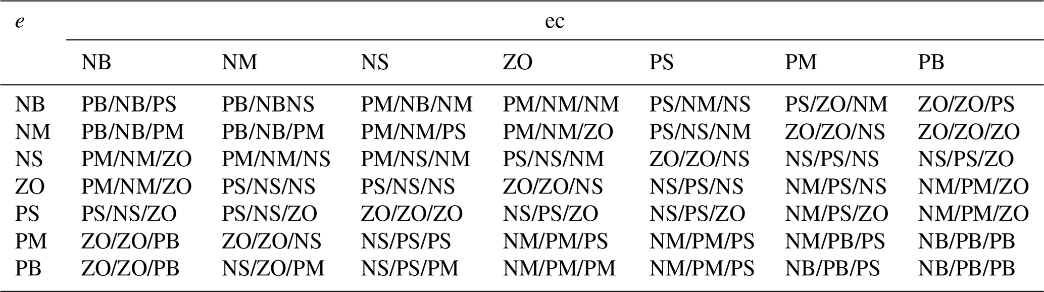
On the basis of practical engineering control experience, the fuzzy control rules for ΔKp, ΔKi, and ΔKd are established as shown in Table 2. Equations (40)–(42) denote the PID parameters in the FPID controller.
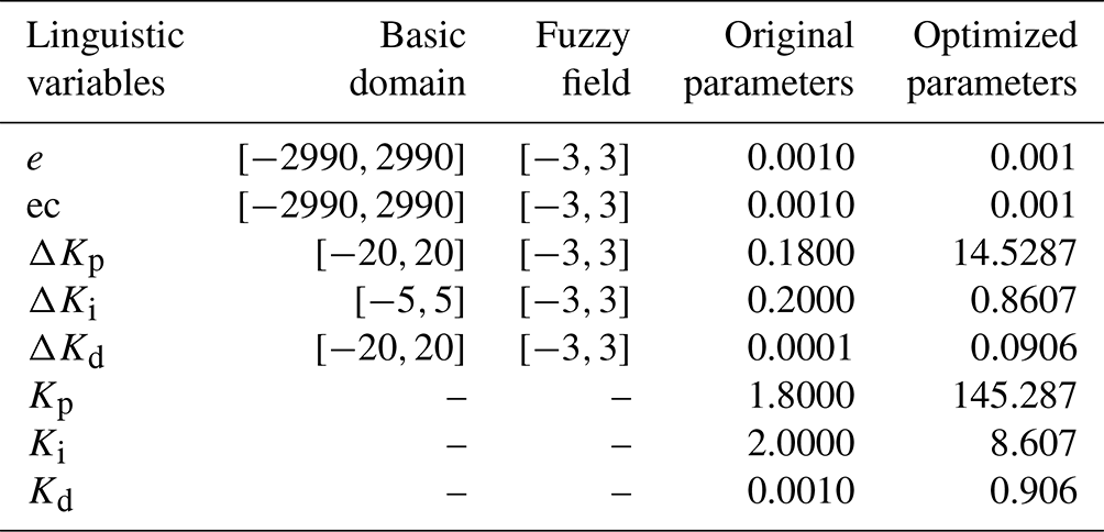
The rated speed of the motor is 3000 rpm, but due to voltage errors, the actual range of the motor speed error is []. The domain of e and ec is [], so the quantization factor is . The control domain for setting the output parameters is also []. In practical engineering, the proportional factor of the FPID controller is generally 1 / 10 of the numerical value in the PID controller. The membership functions and characteristic surfaces of the inputs and outputs are shown in Fig. 10.
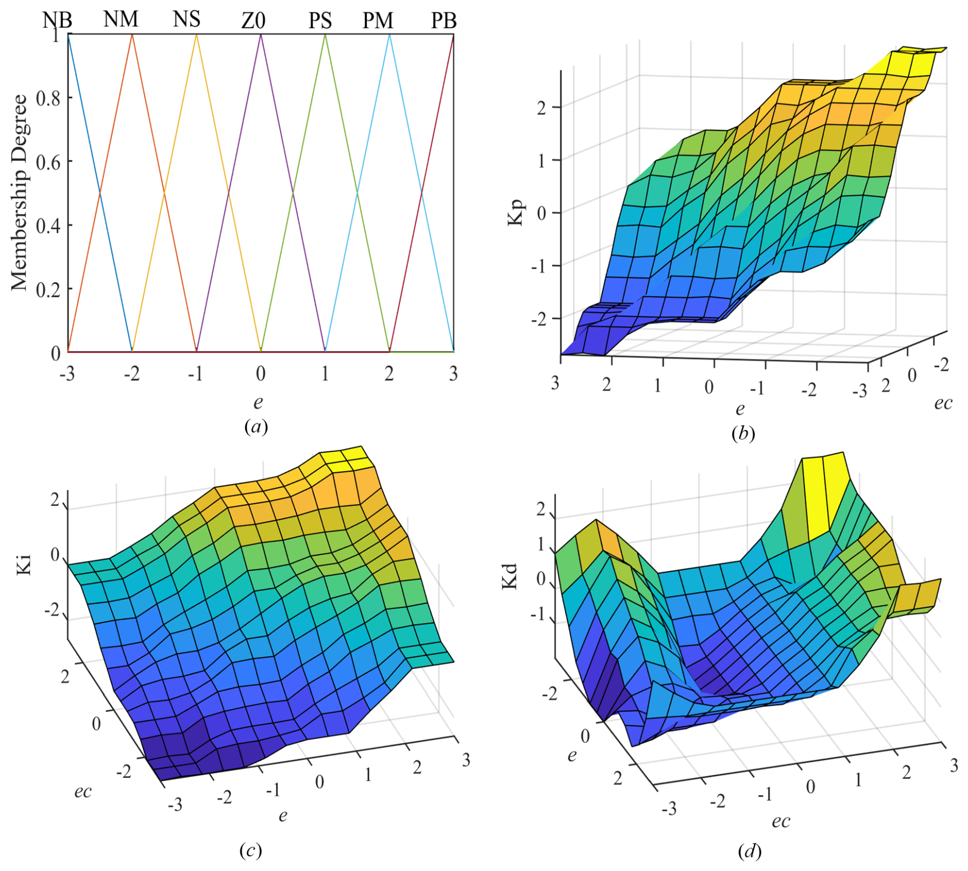
Figure 10Membership function graph of the error and the characteristic surface graph of the three output parameters: (a) domain and membership functions of e, (b) input–output characteristic surface of Kp, (c) input–output characteristic surface of Ki, and (d) input–output characteristic surface of Kd.
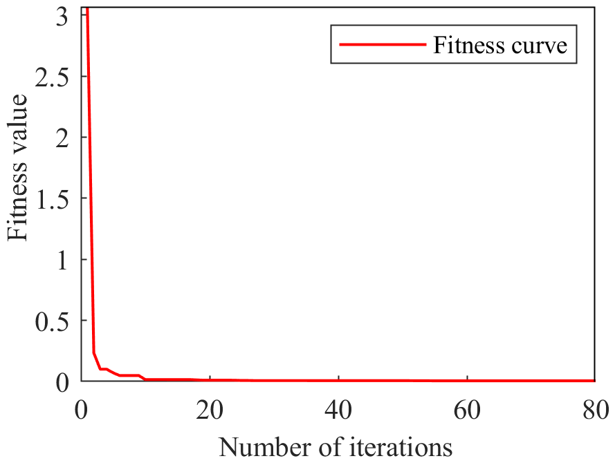
Simulation experiments on the speed curve of the AC servo motor are conducted using MATLAB Simulink to verify the excellent control effect of the optimized FPID controller on the speed of the servo motor. The integral of time multiplied by the absolute error (ITAE) is used as the objective function. The PSO algorithm is employed to optimize the three parameters of the PID controller in the FPID controller as shown in Eq. (43):
Figure 11 shows the convergence curve of the fitness. With the increase in the number of iterations, the fitness value gradually decreases. When the number of iterations exceeds 20, the fitness value stabilizes and approaches 0. The parameters obtained after optimization by the PSO algorithm are Kp=145.2866, Ki=8.6072, and Kd=0.0906, Meanwhile, the three parameters of the PID controller without optimization are determined using the critical proportional coefficient (Borase et al., 2021) to be Kp=1.8, Ki=2, and Kd=0.001. The critical proportional coefficient and the parameter list of the linguistic variables are shown in Tables 3 and 4, respectively.
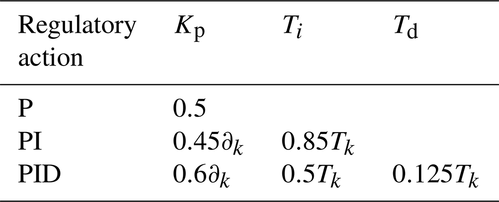
The integral time Ti in the PID controller is set to infinity; the derivative time Td is set to 0; and the proportional coefficient is gradually adjusted from small to large until the system's output response exhibits critical oscillation, obtaining the proportional coefficient ∂k and critical oscillation Tk as shown in Table 3. Simulation experiments are conducted with the target speed set to be the rated speed of the servo motor (Fig. 12).
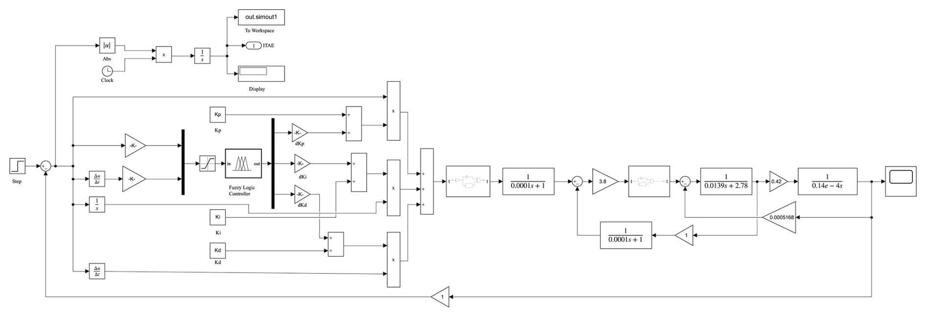
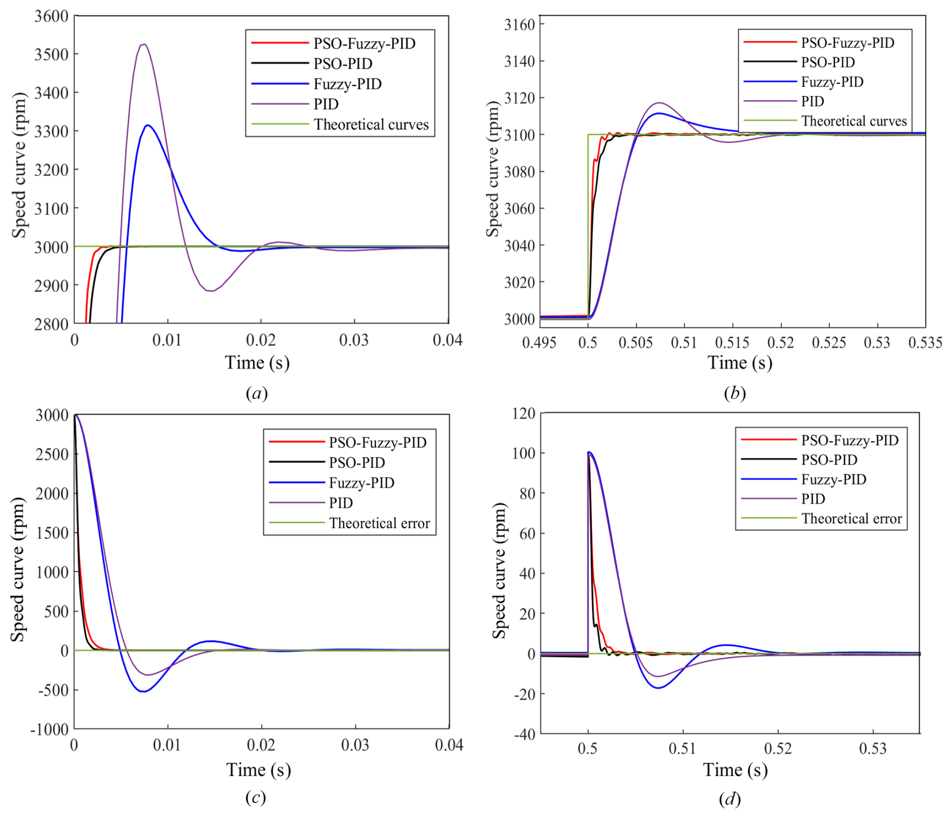
Figure 13Speed response curve and error curve graph of the four controllers: (a) speed response curves, (b) speed response curve after interference, (c) speed error curves, and (d) interference error curves.
Figure 13a shows the speed response curves of the PSO-optimized FPID controller, PSO-optimized PID controller, FPID controller, and PID controller. The response time of the PSO-algorithm-optimized controller is superior to those of the other two controllers, with almost zero overshoot. Figure 13b depicts the speed response curves of the four controllers after a disturbance in 0.5 s, indicating that the optimized controller exhibits excellent disturbance rejection capability. However, the optimized FPID controller shows significant oscillations in response to disturbances, possibly due to the uncertainty introduced by the application of fuzzy logic in the control that affected the controller's performance. Figure 13c and d illustrate the speed error curves and disturbance rejection error curves of the four controllers, respectively, revealing that the errors of the two optimized controllers are significantly smaller than those of the other two controllers. The transient response performance indices of the four controllers are summarized in Table 5.
Table 5Transient response performance indicators of the four controllers.
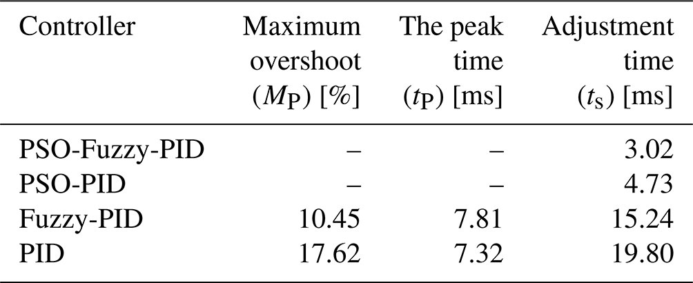
As shown in Table 5 and Fig. 13, the overshoot and peak time of the two controllers optimized by PSO are almost zero. The FPID controller and PID controller both have a large overshoot, with the maximum overshoot (MP) of the PID controller reaching 17.62 %, which is far higher than that of the FPID controller at 10.45 %. The peak time (tP) of the PID controller is 7.32 ms, which is slightly smaller than that of the FPID controller at 7.81 ms. This phenomenon may be due to the longer peak time (tp) of the FPID controller caused by the complex fuzzy logic and inference. Table 5 shows that the adjustment time (ts) of the FPID controller and PID controller after PSO optimization is 3.02 and 4.73 ms, respectively, and that of the ordinary FPID controller and PID controller is 15.24 and 19.80 ms, respectively. In summary, the optimized FPID controller has a better control effect than the optimized PID controller, followed by the FPID controller, and the PID controller has an inferior control effect to the first three controllers.
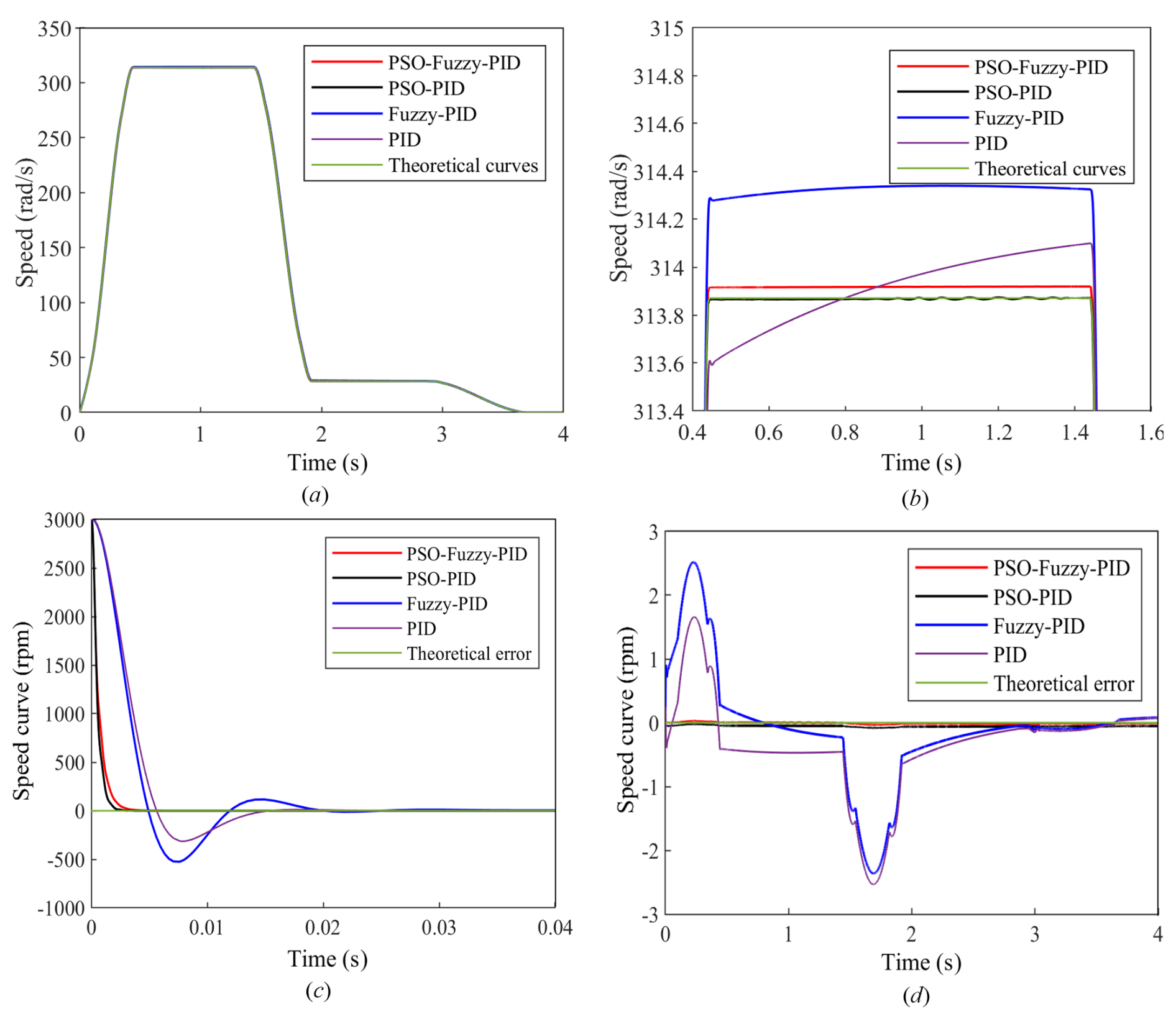
Figure 14Motor speed curve and speed error simulation graph: (a) motor speed curve, (b) locally magnified plot of the motor speed curve from 0.4 to 1.6 s, (c) local magnification of the motor speed curve from 1.9 to 3.1 s, and (d) motor speed error among the four controllers.
Figure 14a shows that the motor speed curves of the four controllers closely match the theoretical curve. In the enlarged views of the speed curves in Fig. 14b and c, the PSO algorithm exhibits a better control effect on the optimized PID controller than on the optimized FPID controller, and the poorest control effect is observed for the PID controller. The error plot in Fig. 14d also indicates that the error after the optimization of PSO is significantly smaller than that for the other two controllers. Considering the good control characteristics of FPID controllers for nonlinear and uncertain systems, this study selects the PSO algorithm to optimize the FPID controller for precise control of the bolt tightening torque.
To verify the control accuracy of the PSO-optimized fuzzy PID controller for the servo motor speed and the accuracy of the tightening system model, this study selects an M6 bolt of grade 8.8 as the tightening target and a Siemens S7-1200 PLC to be used as the controller. The torque values obtained in Sect. 2 are taken as the target for experimental analysis.
Figure 15 shows an experimental setup specifically designed to test the dynamic response of the bolt tightening torque control and the torque output of the drive system. This modular design features precise alignment and high flexibility. The main components are as follows:
-
M6 bolt, which ensures stability of the setup and minimizes measurement errors caused by vibrations and movements;
-
sleeve, which connects the bolt to the elastic coupling, providing damping and absorbing shocks;
-
elastic coupling, which compensates for installation errors, ensures coaxial alignment, and reduces torque shocks;
-
dynamic torque sensor, which continuously monitors torque variations, suitable for high-dynamic-response experiments;
-
planetary reducer, which reduces the motor output speed while increasing torque, thus minimizing energy loss;
-
servo motor, which delivers high-precision rotational motion, simulating complex tightening load conditions.
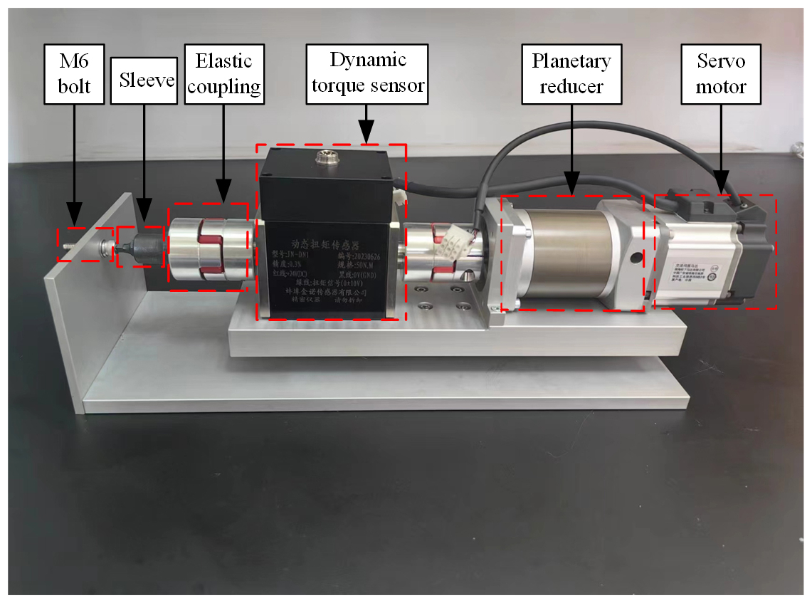
The experimental platform offers high-precision measurements specifically for testing the bolt tightening torque control and torque analysis. It also provides reliable data support for optimizing the torque precision in electric drive systems.
During bolt tightening, the control performance of the PID controller may be limited by nonlinear variations. Therefore, this experiment tests the PSO-optimized FPID controller, FPID controller, and PSO-optimized PID controller. Each controller is subjected to 20 sets of experiments to analyze their precision in controlling the bolt tightening torque. The results are thoroughly analyzed to evaluate the differences in torque control accuracy among these three controllers.
According to the bolt tightening torque test results shown in Fig. 16, the PSO-optimized FPID controller performs the best in terms of optimized control, followed by the FPID controller. The PSO-optimized PID controller exhibits the least effective performance. In the simulation model, the PSO-optimized PID controller demonstrates superior control over the speed curve and speed error compared with the FPID controller. However, the experimental results show the opposite outcome. This discrepancy can be attributed to the nonlinear variations during bolt tightening. In such environments, the performance of the PID controller typically falls short compared with that of the FPID controller in handling time-varying and nonlinear systems.

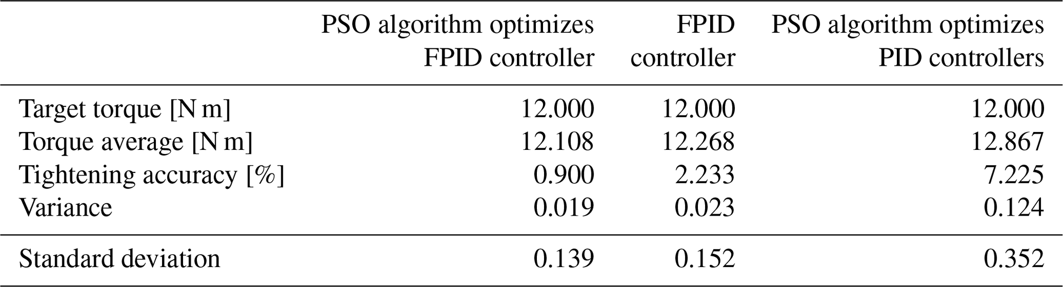
Table 6 presents the parameters related to the bolt tightening torque. According to the data, the torque control precision for the three controllers is 0.9 %, 2.233 %, and 7.225 %, respectively. With respect to variance and standard deviation, the PSO-optimized FPID controller exhibits the smallest deviation, lowest dispersion, and highest tightening precision. This finding confirms the accuracy of the established tightening system model and the servo motor speed curve.
This paper addresses the challenge of controlling tightening torque during bolt connections by proposing a PSO-algorithm-optimized FPID controller based on the torque–angle method. The control system takes the servo motor's speed error as input, and MATLAB Simulink is employed to conduct simulation experiments on the transient response performance of four controllers: the PSO-optimized FPID controller, PSO-optimized PID controller, traditional FPID controller, and PID controller. A bolt tightening test bench is then established to validate the effectiveness of the proposed control method and the accuracy of the physical model.
The experimental results demonstrate two key findings:
-
The PSO-optimized controllers exhibit nearly negligible overshoot and a 5-fold improvement in response speed compared to conventional FPID and PID controllers. This optimization allows for rapid identification of the optimal parameter combinations, effectively eliminating system bias, enhancing response speed, and preventing oscillations caused by excessive overshoot. These improvements significantly bolster the system's adaptability and disturbance rejection capabilities.
-
By optimizing the PID parameters using the PSO algorithm and integrating them with the FLC, this method successfully addresses the uncertainties and nonlinear variations inherent in bolt tightening. An average deviation of 0.108 N m is achieved between the tightening torque and the target torque, resulting in a control accuracy of 0.9 %. This approach effectively improves the quality of bolt tightening, ensuring that the torque accuracy remains within 3 %, thereby enhancing the reliability of the bolt assembly.
However, the PSO-optimized fuzzy PID controller has limitations due to its reliance on the quality of fuzzy rules and membership functions and potential suboptimal convergence, which can vary across different applications. Future research should focus on improving these designs and refining PSO convergence using hybrid techniques. Additionally, real-time adaptive control strategies, supported by machine learning, along with multivariable control systems and advanced sensors, could improve handling of dynamic uncertainties and enhance system robustness and control accuracy without affecting existing experimental results.
All the data used in this paper can be obtained upon request from the corresponding author.
XC provided design ideas and wrote the conclusion of the article. ZG carried out the theoretical analysis of bolted connections and completed the first draft of the paper. ZG and JK built a prototype and carried out experimental verification.
The contact author has declared that none of the authors has any competing interests.
Publisher's note: Copernicus Publications remains neutral with regard to jurisdictional claims made in the text, published maps, institutional affiliations, or any other geographical representation in this paper. While Copernicus Publications makes every effort to include appropriate place names, the final responsibility lies with the authors.
This research was funded by the Scientific Research Foundation of Zhejiang Sci-Tech University (grant no. 11133132612005) and the Young Talent support project (grant no. 11130531282004).
This research has been supported by the Zhejiang Sci-Tech University (grant nos. 11133132612005 and 11130531282004).
This paper was edited by Peng Yan and reviewed by three anonymous referees.
Ahmadnia, M., Hajipour, A., and Tavakoli, H.: Robust variable-order fractional PID-LP fuzzy controller for Automatic Voltage Regulator systems, Appl. Soft. Comput., 167, 112268, https://doi.org/10.1016/j.asoc.2024.112268, 2024.
Alenizi, F. A., Abbasi, S., Hussein Mohammed, A., and Masoud Rahmani, A.: The artificial intelligence technologies in Industry 4.0: A taxonomy, approaches, and future directions, Comput. Ind. Eng., 185, 109662, https://doi.org/10.1016/j.cie.2023.109662, 2023.
Altbawi, S. M. A., Mokhtar, A. S. Bin, Jumani, T. A., Khan, I., Hamadneh, N. N., and Khan, A.: Optimal design of Fractional order PID controller based Automatic voltage regulator system using gradient-based optimization algorithm, Journal of King Saud University – Engineering Sciences, 36, 32–44, https://doi.org/10.1016/j.jksues.2021.07.009, 2024.
Althoefer, K., Lara, B., Zweiri, Y. H., and Seneviratne, L. D.: Automated failure classification for assembly with self-tapping threaded fastenings using artificial neural networks, Proc. Inst. Mech. Eng. C J. Mech. Eng. Sci., 222, 1081–1095, https://doi.org/10.1243/09544062JMES546, 2008.
An, Z., Li, D., Zhang, C., Luo, Y., and Zhang, J.: Behaviours of thermal management system with micro channels for cylindrical Lithium-ion cells under Fuzzy-PID control strategy, Appl. Therm. Eng., 233, 121089, https://doi.org/10.1016/j.applthermaleng.2023.121089, 2023.
Borase, R. P., Maghade, D. K., Sondkar, S. Y., and Pawar, S. N.: A review of PID control, tuning methods and applications, Int. J. Dyn. Control., 9, 818–827, https://doi.org/10.1007/s40435-020-00665-4, 2021.
Boudia, A., Messalti, S., Harrag, A., and Boukhnifer, M.: New hybrid photovoltaic system connected to superconducting magnetic energy storage controlled by PID-fuzzy controller, Energy Convers. Manag., 244, 114435, https://doi.org/10.1016/j.enconman.2021.114435, 2021.
Chang, J.-L.: Discrete-time PID observer design for state and unknown input estimations in noisy measurements, Int. J. Control Autom. Syst., 13, 816–822, https://doi.org/10.1007/s12555-014-0151-z, 2015.
Charkoutsis, S. and Kara-Mohamed, M.: A Particle Swarm Optimization tuned nonlinear PID controller with improved performance and robustness for First Order Plus Time Delay systems, Results in Control and Optimization, 12, 100289, https://doi.org/10.1016/j.rico.2023.100289, 2023.
Chen, R., Tang, J., Xu, F., Du, C., Cui, Y., and Liu, K.: Influence of oil film nonlinearity on identification accuracy of dynamic characteristic coefficient of heavy-duty sliding bearing, J. Braz. Soc. Mech. Sci., 45, 233, https://doi.org/10.1007/s40430-023-04157-2, 2023.
Deters, C., Secco, E. L., Wuerdemann, H. A., Lam, H. K., Seneviratne, L. D., and Althoefer, K.: Model-free fuzzy tightening control for bolt/nut joint connections of wind turbine hubs, in: 2013 IEEE International Conference on Robotics and Automation (ICRA), Karlsruhe, Germany, 6–10 May 2013, 270–276, https://doi.org/10.1109/ICRA.2013.6630587, 2013.
Deters, C., Lam, H. K., Secco, E. L., Wurdemann, H. A., Seneviratne, L. D., and Althoefer, K.: Accurate Bolt Tightening Using Model-Free Fuzzy Control for Wind Turbine Hub Bearing Assembly, IEEE T. Contr. Syst. T., 23, 1–12, https://doi.org/10.1109/TCST.2014.2309854, 2015.
Dhayagude, N., Gao, Z., and Mradt, F.: Fuzzy Logic Control Of Automated Screw Fastening, Robot. Com.-Int. Manuf., 235–242, 1996.
Fang, S., Cao, J., Zhang, Z., Zhang, Q., and Cheng, W.: Study on High-Speed and Smooth Transfer of Robot Motion Trajectory Based on Modified S-Shaped Acceleration/Deceleration Algorithm, IEEE Access, 8, 199747–199758, https://doi.org/10.1109/ACCESS.2020.3035430, 2020.
Feng, Y., Wu, D., Stewart, M. G., and Gao, W.: Past, current and future trends and challenges in non-deterministic fracture mechanics: A review, Comput. Methods Appl. Mech. Eng., 412, 116102, https://doi.org/10.1016/j.cma.2023.116102, 2023.
Gao, Q., Sun, Z., Yang, G., Hou, R., Wang, L., and Hou, Y.: A novel active disturbance rejection-based control strategy for a gun control system, J. Mech. Sci. Technol., 26, 4141–4148, https://doi.org/10.1007/s12206-012-0879-4, 2012.
Geng, G., Jiang, F., Chai, C., Wu, J., Zhu, Y., Zhou, G., and Xiao, M.: Design and experiment of magnetic navigation control system based on fuzzy PID strategy, Mech. Sci., 13, 921–931, https://doi.org/10.5194/ms-13-921-2022, 2022.
Gün, A.: Attitude control of a quadrotor using PID controller based on differential evolution algorithm, Expert. Syst. Appl., 229, 120518, https://doi.org/10.1016/j.eswa.2023.120518, 2023.
Gür, Y. and Cen, G.: Comparison of finite element analysis results with strain gauge measurements of a front axle housing, Mech. Sci., 15, 257–268, https://doi.org/10.5194/ms-15-257-2024, 2024.
Hagiwara, T., Yamada, K., Hoang, A. C., and Aoyama, S.: The Parameterization of All Plants Stabilized by a PID Controller, Key Eng. Mater., 534, 173–181, https://doi.org/10.4028/www.scientific.net/KEM.534.173, 2013.
Hasan, M. M., Rana, M. S., Tabassum, F., Pota, H. R., and Roni, M. H. K.: Optimizing the initial weights of a PID neural network controller for voltage stabilization of microgrids using a PEO-GA algorithm, Appl. Soft. Comput., 147, 110771, https://doi.org/10.1016/j.asoc.2023.110771, 2023.
He, M., Gong, W., Wang, J., Qi, P., Tao, Z., Du, S., and Peng, Y.: Development of a novel energy-absorbing bolt with extraordinarily large elongation and constant resistance, Int. J. Rock Mech. Min., 67, 29–42, https://doi.org/10.1016/j.ijrmms.2014.01.007, 2014.
Hermassi, M., Krim, S., Kraiem, Y., and Hajjaji, M. A.: Adaptive neuro fuzzy technology to enhance PID performances within VCA for grid-connected wind system under nonlinear behaviors: FPGA hardware implementation, Comput. Electr. Eng., 117, 109264, https://doi.org/10.1016/j.compeleceng.2024.109264, 2024.
Hou, R., Wang, L., Gao, Q., Hou, Y., and Wang, C.: Indirect adaptive fuzzy wavelet neural network with self- recurrent consequent part for AC servo system, ISA Trans., 70, 298–307, https://doi.org/10.1016/j.isatra.2017.04.010, 2017.
Hu, J., Zhang, K., Cheng, H., and Qi, Z.: An experimental investigation on interfacial behavior and preload response of composite bolted interference-fit joints under assembly and thermal conditions, Aerosp. Sci. Technol., 103, 105917, https://doi.org/10.1016/j.ast.2020.105917, 2020.
Jia, L., Yang, J., Gu, X., Liu, Z., and Ma, X.: Composite synchronization of three inductor motors with a circular distribution by a fuzzy proportional–integral–derivative method in a vibration system, Mech. Sci., 14, 143–158, https://doi.org/10.5194/ms-14-143-2023, 2023.
Jia, Z., Bhatia, A., Aronson, R. M., Bourne, D., and Mason, M. T.: A Survey of Automated Threaded Fastening, IEEE T. Autom. Sci. Eng., 16, 298–310, https://doi.org/10.1109/TASE.2018.2835382, 2019.
Jiang, K., Liu, Z., Yang, C., Zhang, C., Tian, Y., and Zhang, T.: Effects of the joint surface considering asperity interaction on the bolted joint performance in the bolt tightening process, Tribol. Int., 167, 107408, https://doi.org/10.1016/j.triboint.2021.107408, 2022.
Kashyap, A. K. and Parhi, D. R.: Particle Swarm Optimization aided PID gait controller design for a humanoid robot, ISA Trans., 114, 306–330, https://doi.org/10.1016/j.isatra.2020.12.033, 2021.
Li, W., Xu, H., Liu, X., Wang, Y., Zhu, Y., Lin, X., Wang, Z., and Zhang, Y.: Regenerative braking control strategy for pure electric vehicles based on fuzzy neural network, Ain Shams Engineering Journal, 15, 102430, https://doi.org/10.1016/j.asej.2023.102430, 2024.
Lin, Q., Xue, X., Guo, Z., Zhao, Y., and Chen, Y.: Test on shear behavior of less-tightened high-strength bolted connections, Structures, 34, 3622–3639, https://doi.org/10.1016/j.istruc.2021.09.104, 2021.
Liu, R., Pan, F., and Diao, Q.: Research on Thread Tightening Torque Control Method Based on Fuzzy Algorithm, in: 2020 39th Chinese Control Conference (CCC), Shenyang, China, 27–29 July 2020, 2216–2220, https://doi.org/10.23919/CCC50068.2020.9188972, 2020.
Liu, S., Ge, S. S., Qin, G., and Li, M.: An Automatic Screw Tightening Shaft Based on Enhanced Variable Gain PID Control, International Journal of Simulation-Systems, Science and Technology, 16, 14.1–14.9, https://doi.org/10.5013/IJSSST.a.16.05.14, 2015.
Liu, S., Ge, S. S., and Tang, Z.: A modular designed bolt tightening shaft based on adaptive fuzzy backstepping control, Int. J. Control Autom. Syst., 14, 924–938, https://doi.org/10.1007/s12555-015-0008-0, 2016.
Liu, W., Wang, Z., Zeng, N., Alsaadi, F. E., and Liu, X.: A PSO-based deep learning approach to classifying patients from emergency departments, Int. J. Mach. Learn. Cyb., 12, 1939–1948, https://doi.org/10.1007/s13042-021-01285-w, 2021.
Liu, X. and Chen, M.: Robust trajectory tracking control for collaborative robots based on learning feedback gain self-adjustment, Mech. Sci., 14, 293–304, https://doi.org/10.5194/ms-14-293-2023, 2023.
Liu, Z., Wang, Y., Dong, X., Zhang, C., and Li, Y.: A novel model for evaluating preload based on spectral problem in system with double-bolted connections, Appl. Math. Model., 102, 21–34, https://doi.org/10.1016/j.apm.2021.09.016, 2022a.
Liu, Z., Yan, X., Zheng, M., Wang, Y., Chen, W., and Li, Y.: The effect of tightening again on bolt loosening under transverse load: Experimental and finite element analysis, Structures, 44, 1303–1311, https://doi.org/10.1016/j.istruc.2022.08.049, 2022b.
Manuel, N. L., İnanç, N., and Lüy, M.: Control and performance analyses of a DC motor using optimized PIDs and fuzzy logic controller, Results in Control and Optimization, 13, 100306, https://doi.org/10.1016/j.rico.2023.100306, 2023.
Matsumura, M., Itou, S., Hibi, H., and Hattori, M.: Tightening torque estimation of a screw tightening robot, in: Proceedings of 1995 IEEE International Conference on Robotics and Automation, Nagoya, Japan, 13–17 May 1995, 2108–2112, https://doi.org/10.1109/ROBOT.1995.525572, 1995.
Merrikh-Bayat, F., Mirebrahimi, N., and Khalili, M. R.: Discrete-time fractional-order PID controller: Definition, tuning, digital realization and some applications, Int. J. Control Autom. Syst., 13, 81–90, https://doi.org/10.1007/s12555-013-0335-y, 2015.
Muftah, M. N., Faudzi, A. A. M., Sahlan, S., and Shouran, M.: Modeling and Fuzzy FOPID Controller Tuned by PSO for Pneumatic Positioning System, Energies (Basel), 15, 3757, https://doi.org/10.3390/en15103757, 2022.
Muftah, M. N., Faudzi, A. A. M., Sahlan, S., and Mohamaddan, S.: Fuzzy Fractional Order PID Tuned via PSO for a Pneumatic Actuator with Ball Beam (PABB) System, Fractal Fract., 7, 416, https://doi.org/10.3390/fractalfract7060416, 2023.
Nah, H.-S. and Choi, S.-M.: Evaluate the Clamping Force of Torque-Shear High Strength Bolts, Int. J. Steel Struct., 18, 935–946, https://doi.org/10.1007/s13296-018-0066-2, 2018.
Noble, R.: Working Bolts Near to Yield: Theory, Experience and Recommended Practice, in: Volume 3: Design and Analysis, American Society of Mechanical Engineers, https://doi.org/10.1115/PVP2013-97956, 2013.
Shao, Y., Liu, J., Huang, J., Hu, L., Guo, L., and Fang, Y.: The Implementation of Fuzzy PSO-PID Adaptive Controller in Pitch Regulation for Wind Turbines Suppressing Multi-Factor Disturbances, Front. Energy Res., 9, 828281, https://doi.org/10.3389/fenrg.2021.828281, 2022.
Shi, B., Luo, Z., Li, L., Li, Y., and Sun, K.: Joint degradation and its effect on rotor vibration characteristics considering bolt assembly process, Mech. Syst. Signal Process., 211, 111208, https://doi.org/10.1016/j.ymssp.2024.111208, 2024.
Shoberg, R. S.: Mechanical Testing of Threaded Fasteners and Bolted Joints, in: Mechanical Testing and Evaluation, ASM International, 811–835, https://doi.org/10.31399/asm.hb.v08.a0003323, 2000.
Song, B., Wang, Z., and Zou, L.: An improved PSO algorithm for smooth path planning of mobile robots using continuous high-degree Bezier curve, Appl. Soft. Comput., 100, 106960, https://doi.org/10.1016/j.asoc.2020.106960, 2021.
Song, Q. H., Xiao, L. J., Song, Q. J., Jiang, H. Y., and Liu, X. J.: Adaptive multiswarm particle swarm optimization for tuning the parameter optimization of a three-element dynamic vibration absorber, Mech. Sci., 13, 505–517, https://doi.org/10.5194/ms-13-505-2022, 2022.
Štimac, G., Braut, S., and Žigulić, R.: Comparative analysis of PSO algorithms for PID controller tuning, Chin. J. Mech. Eng., 27, 928–936, https://doi.org/10.3901/CJME.2014.0527.302, 2014.
Sun, X., Liu, N., Shen, R., Wang, K., Zhao, Z., and Sheng, X.: Nonlinear PID Controller Parameters Optimization Using Improved Particle Swarm Optimization Algorithm for the CNC System, Appl. Sci., 12, 10269, https://doi.org/10.3390/app122010269, 2022.
Tsuji, H. and Maruyama, K.: Estimation of Yield Clamping Force Based on Rigid-Plastic Model, in: Reliability, Stress Analysis, and Failure Prevention Issues in Adhesive and Bolted Connections, American Society of Mechanical Engineers, 157–162, https://doi.org/10.1115/IMECE1999-1195, 1999.
Wang, B., Lei, Y., Fu, Y., and Geng, X.: Autonomous vehicle trajectory tracking lateral control based on the terminal sliding mode control with radial basis function neural network and fuzzy logic algorithm, Mech. Sci., 13, 713–724, https://doi.org/10.5194/ms-13-713-2022, 2022.
Wu, Z., Du, W., Zhang, G., and Wang, J.: Fuzzy Control Based on Torque and Angle Method for Bolt Assembling System, in: 2020 Prognostics and Health Management Conference (PHM-Besançon), Besançon, France, 4–7 May 2020, 214–218, https://doi.org/10.1109/PHM-Besancon49106.2020.00042, 2020a.
Wu, Z., Zhang, G., Du, W., Wang, J., Han, F., and Qian, D.: Torque control of bolt tightening process through adaptive-gain second-order sliding mode, Meas. Control, 53, 1131–1143, https://doi.org/10.1177/0020294020932354, 2020b.
Xie, S., Sun, H., Xie, Y., and Chen, X.: Tuning of fuzzy controller with arbitrary triangular input fuzzy sets based on proximal policy optimization for time-delays system, J. Process. Control, 129, 103059, https://doi.org/10.1016/j.jprocont.2023.103059, 2023.
Yang, C., Wang, X., Wang, Q., and Ou, J.: Seismic performance of cruciform bolted joints with various reinforcing details in modular steel construction, Eng. Struct., 285, 116069, https://doi.org/10.1016/j.engstruct.2023.116069, 2023.
Yao, S.-J., Yang, X.-H., Bai, C.-X., Lv, Y., Zhao, D.-X., and Wang, Z.-H.: Research on anti-rollover control of three-axle rescue vehicle based on active suspension and differential braking, Mech. Sci., 15, 501–514, https://doi.org/10.5194/ms-15-501-2024, 2024.
Zhan, W., Wu, J., Shao, F., and Huang, C.: Research on Torque-Angle Tightening of High Strength Bolt in Internal Combustion Engine, Proceedings of the FISITA 2012 World Automotive Congress, Volume 2: Advanced Internal Combustion Engines (II), Springer Berlin Heidelberg, Berlin, Heidelberg, 941–949, https://doi.org/10.1007/978-3-642-33750-5_9, 2013.
Zhang, H., Ding, L., Zhang, W., and Li, C.: Performance analysis of an electro-hydrostatic actuator with high-pressure load sensing based on fuzzy PID, Mech. Sci., 12, 529–537, https://doi.org/10.5194/ms-12-529-2021, 2021.
Zhang, Y. and Xiao, X.: Fuzzy PID control system optimization and verification for oxygen-supplying management in live fish waterless transportation, Information Processing in Agriculture, Information Processing in Agriculture, 11, 421–437, https://doi.org/10.1016/j.inpa.2023.06.001, 2024.
Zheng, M., Chen, W., Yan, X., Liu, Z., and Abdel Wahab, M.: Finite element analysis of bolted joints under torsional loads, Tribol. Int., 201, 110188, https://doi.org/10.1016/j.triboint.2024.110188, 2025.
- Abstract
- Introduction
- Mathematical model of bolted connection
- Design of the torque–speed curve and modeling analysis of the tightening mechanism
- Design and simulation of the PSO-optimized FPID controller
- Experimental results and discussion
- Conclusion
- Data availability
- Author contributions
- Competing interests
- Disclaimer
- Acknowledgements
- Financial support
- Review statement
- References