the Creative Commons Attribution 4.0 License.
the Creative Commons Attribution 4.0 License.
Gait planning of a 4–5R rolling mechanism based on the planar 6R single-loop chain
Qing Liu
Qianqian Zhang
Shouzhen Kang
Ziyi Pei
Jialei Li
Yezhuo Li
Yue Yan
Yuhao Liang
Xinyu Wang
This paper proposes a 4–5R rolling mechanism based on the spatial extension design of a planar 6R single-loop chain. By analyzing the locomotion of the planar equivalent form, a modular gait theory integrating different modes of gait with high efficiency, low energy consumption, and high speed is established. A unified kinematic strategy expression, encapsulated in the form of the gait period table, is tailored for the kinematic chain's gait on the flat terrain. A contrast gait is conducted to ascertain its velocity parameters and volatility of the center of mass (CM). By optimizing the corresponding indicators, two distinct gait patterns are achieved: a faster speed gait that prioritizes increased speed and a steady gait that emphasizes stability with reduced CM volatility. Drawing from the mobility analysis and simulation outcomes of the planar 6R single-loop kinematic chain, a theory of locomotion for a closed-chain linkage mechanism in space is proposed. A locomotion strategy on the flat ground is derived, and a unified evaluation index is proposed. Finally, the feasibility of the two working modes is verified using a physical prototype. The theoretical work in this paper simplifies the design process of closed-chain linkage robots and improves the mobility performance of closed-chain linkage robots. It lays the foundation for researching new types of closed-chain linkage robots.
- Article
(4501 KB) - Full-text XML
-
Supplement
(65280 KB) - BibTeX
- EndNote
Mobile robots have been a substantial contributor in various sectors, including industry, service, medical, and socialization sectors (Tzafestas, 2018). The application of mobile robots has gradually extended to the research of photographic equipment carriers in ecological photography and terrain mapping engineering. Photographic robots include underwater (Debruyn et al., 2020), aerospace (Ivosevic et al., 2015), and terrestrial types (Ross et al., 2021; Mortezapoor et al., 2022). Terrestrial robots are further categorized into wheeled, tracked, footed, and closed-chain linkage types (Teng et al., 2024; Nodehi et al., 2022; Zi et al., 2024; Hu et al., 2023). Ecological photography environments are variable (Pringle et al., 2023), and traditional mobile robots present certain limitations. Among them, the closed-chain linkage can be referred to as closed kinematic chains or closed-chain mechanisms. These types of mobile robots typically consist of multiple links or modules arranged in polygon configurations and interconnected through rotating joints. Compared to open-chain robots, the moving parts of closed-chain robots can be lighter, which can lead to greater acceleration and higher efficiency of the end effector (Guo et al., 2001). Therefore, the planar 6R single-loop chain is particularly suitable for terrestrial ecological photography due to its simple structure, high motion efficiency, and operational space that mimics natural movements. The planar 6R single-loop chain is derived from the conventional six-bar mechanism. This chain eschews a rigid frame and is propelled by actively rotating joints that correspond to its degrees of freedom. Through structural and gait planning optimization, the problem of disturbing animals (Adams et al., 2022) has been effectively solved while improving the quality of captured images and videos.
Closed-chain linkage robots were proposed to solve the problems of open-chain structures with many degrees of freedom, limited stiffness, and complex control systems for footed robots (Kim et al., 2011). Typically, not all joints of closed-chain mechanisms are actuated (Ghorbel et al., 2000). Early on, Bicchi and Prattichizzo (2000) proposed kinematic manipulability indices for active and passive joints for closed-chain robots, and Mori and Omata (2002) coupled open kinematic chains and reconfigured them into closed-chain robots. The tetrahedron (TET) walker has a closed-chain linkage mechanism with good mobility (Curtis et al., 2007). To et al. (2012) proposed an improved kinematic model for calibration purposes. Nguyen et al. (2014) developed a global kinematic model to improve the position accuracy.
For partially closed-chain linkage robots, the plane of motion can be equated to a planar 6R single-loop kinematic chain. He et al. (2019) proposed adding wheels to the platform of a planar 6R single-loop kinematic chain to achieve faster speeds and spatial steering. Wang et al. (2018) proposed a multi-mode 4-RSR parallel mobile mechanism moving in a 6R chain rolling mode. Park et al. (2019) proposed a variable geometry truss robot (VGT), with a movement strategy that is similar to a planar 6R single-loop kinematic chain. Li et al. (2020) and Zhao et al. (2023) proposed a novel deformable tetrahedron rolling mechanism based on the URU branch (Li et al., 2020; Zhao et al., 2023). A novel hexagon rolling mechanism designed by Zhang et al. (2022) is driven by a central actuator. Additionally, a hexagonal kinematic chain robot has been designed to exhibit four different rolling gaits and tested experimentally (Stanley et al., 2022). While closed-chain systems have advantages over open chains in terms of rigidity of the overall mechanism, motion planning is more complex due to the need to maintain a closed-ring structure (Szynkiewicz et al., 2011).
The basic idea of a closed-chain linkage robot is to be able to achieve stable and continuous periodic movement, which requires stability criterion and gait planning. The zero moment point method (ZMP) solves the problem of discriminating the dynamic stability of a robot (Kim et al., 2018). For the closed-chain link robots, the problem of how to make the robot more stable translates into the issue of how to make the unstable state of the robot controllable. There are two research directions for gait planning. One is based on bionic principles and is more typically a motion control approach with a central pattern generator (CPG) (Yu et al., 2016). CPG-based robot control can achieve multi-modal gaits through a single network model (Zhang et al., 2021). Another type of control idea is model-based control. The best-known model is the spring-loaded inverted pendulum (SLIP) model, whose simplicity and effectiveness in modeling gait make it possible to better interpret walking and running gait and integrate them into a single model (Saar et al., 2017; Piovan and Byl, 2015). Current research on closed-chain linkage mobile robots has mainly focused on demonstrating the feasibility of mobility, with only minor coverage of their mobility capabilities and evaluation systems.
In this paper, a theoretical study of a planar 6R single-loop kinematic chain has been carried out, which is used as the basis for the mathematical modeling, kinematics analysis, and gait planning of a 4–5R rolling mechanism. A unified kinematic strategy expression, encapsulated in the form of the gait period table, is tailored for the kinematic chain's gait on the flat terrain. On this basis, three evaluation indicators are proposed: gait period, τ; drive effectiveness, η; and the volatility of CM, δ. By constraining these three evaluation indicators, different gaits can be proposed. Furthermore, by optimizing the corresponding indicators, two distinct gait patterns are achieved: a faster speed gait that prioritizes increased speed and a steady gait that emphasizes stability with reduced CM volatility. A novel theory concerning speed and steady gait has been introduced that is aimed at enhancing performance metrics when compared to the conventional gait.
The rest of the paper is organized as follows. The mechanism design and kinematic model are introduced in Sect. 2. The analyses of three gaits on flat ground are presented in Sect. 3. Sections 4 and 5 present the simulation and prototype experiments to test and verify the theoretical model, respectively. Section 6 provides a summary and outlook.
2.1 Structure design
The sketch model of the 4–5R rolling mechanism is depicted in Fig. 1a. The mechanism comprises two identical platforms: the upper platform (A5B5C5D5) and the lower platform (A1B1C1D1) along with four symmetrical branches (A2A3A4, B2B3B4, C2C3C4, and D2D3D4) (Tian et al., 2017). The upper links (A5C5 and B5D5) and the lower links (A1C1 and B1D1) are constructed as diagonal lines of two identical platforms. The mechanism is equipped with a total of 20 revolute joints (R joints), consisting of 12 active R joints and 8 passive R joints.
The 12 motors are strategically placed on each active joint to control the locomotion of the mechanism. The four branches are capable of rotating around the corners of the square platforms independently. During turning maneuvers, these branches execute coordinated rotations, facilitating the mechanism's change in direction. The parallel structure enables the platform to vertically and horizontally maneuver in working mode (Li et al., 2017), which extends its detection capabilities and adaptability to diverse environments as illustrated in Fig. 1b. Therefore, the mechanism has the prospect of using cameras as variant gimbals, suitable for use in ecological photography and topographic survey engineering.
The locomotion plane of the mechanism is analogous to a planar 6R single-loop kinematic chain, where a single step of locomotion involves at least four distinct phases and postures (Li et al., 2018) as shown in Fig. 1c. By considering the various stages and postures during locomotion, a variety of motion modes and gaits can be engineered to suit specific operational requirements.
2.2 Mathematical model
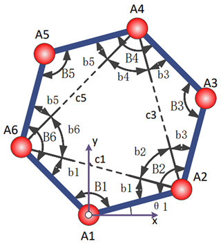
Based on the characteristics of the mechanism and locomotion, the kinematic model of the 4–5R rolling mechanism can be equivalent to the planar 6R single-loop kinematic chain. As shown in Fig. 2, vertex A1 remains in contact with the ground during bridging and overturning process. Therefore, using A1 as the origin establishes the kinematic analysis model of the mechanism. θ1 is the angle between touchdown link A6A1 and the horizontal direction.
Considering the unique attributes of its mechanism and movement, the kinematic model of the 4–5R rolling mechanism can be effectively equated to a planar 6R single-loop kinematic chain. As depicted in Fig. 2, vertex A1 maintains continuous contact with the ground throughout the bridging and overturning procedures. Consequently, employing A1 as the reference point for the origin establishes the kinematic analysis model of the mechanism. Here, θ1 denotes the angle formed between the touchdown link A6A1 and the horizontal plane.
The plane hexagon possesses 3 degrees of freedom. Angles B1, B3, and B5 serve as the driving parameters, pivotal in determining the positional coordinates of the vertices. The spatial coordinates of vertices A1, A2, A3, A4, A5, and A6 are articulated through the length, l, and the angles B1, B2, B3, B4, B5, and B6. The formulas of vertices are shown in Eq. (1).
where
The plane 6R single-loop kinematic chain member is a homogeneous link of mass, mli, and the vertex mass is mAi. By employing the closed-loop vector method, the CM of the mechanism, rCM, can be articulated as in Eq. (3).
Consequently, the interrelation between the CM coordinates and the driving angle can be deduced by integrating the aforementioned equations. This synthesis lays the groundwork for the formulation of mobile strategic expressions.
3.1 Evaluation indicators
The planar 6R single-loop kinematic chain, with its inherent multiple degrees of freedom, exhibits non-uniqueness in both its specific configurations and its transitional states. To streamline the comparison process, the following evaluation criteria have been established:
-
Gait period, τ. It is recognized that the velocity of the CM in a planar 6R single-loop kinematic chain is influenced by the maximum angular velocity attainable by the actuating joints and the chosen locomotion strategy. To facilitate a comparison among various gaits, we assume that the fastest angular velocity achievable at the driving angles for each gait is , meaning that the minimum time required for a 1° change in the driving angles is 1t. Additionally, the gait period, denoted by τ, is defined as the number of time units necessary to complete one step of locomotion. Under identical conditions, a smaller τ indicates a higher average speed.
-
Drive effectiveness, η. It serves as a metric to quantify the efficacy with which the driving angles contribute to the locomotion process. This parameter is determined by the displacement in the x direction of the CM relative to a change in the driving angle. A positive value of η signifies that an increase in the driving angle propels the CM forward. The larger the value of η, the more significant the change in CM's position, thereby indicating a more effective locomotion.
-
The volatility of CM, δ. The concept of CM volatility, denoted by δ, is pivotal for assessing the smoothness of locomotion, closely tied to the one-step locomotion strategy previously discussed. This measure is articulated as a ratio: it compares the disparity between the maximum (rCMy max) and minimum (rCMy min) vertical displacements of the CM to the length (l) of the support link. A lower δ indicates a smoother locomotion pattern as it reflects less variation in CM's vertical movement.
3.2 Locomotion strategy
The gait for the planar 6R single-loop kinematic chain is specifically tailored for operation on flat terrain. Assuming that the hexagonal link is lightweight and each vertex has a mass denoted as mAi, the position of the CM rCM of the mechanism can be mathematically represented as in Eq. (6).
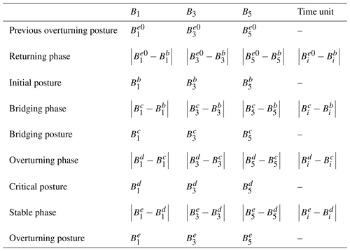
The gait periodic table serves as an overarching framework to delineate the gait patterns of the planar 6R single-loop kinematic chain, as detailed in Table 1. This comprehensive representation encapsulates the various locomotion strategies, providing a systematic overview of the chain's dynamic behavior.
Therefore, the gait period of the general gait can be obtained as follows:
3.3 Contrast gait
First, the contrast gait is introduced and the stages of the contrast gait are defined as follows:
- i.
Returning phase. During this phase, the mechanism transitions from the previous overturning posture to the initial posture. In the initial posture, link A6A1 is in contact with the ground, while the angles at joints B1, B3, and B5 are each set at 120°.
- ii.
Bridging phase. In this phase, the link A6A1 maintains its position, while A1A2 rotates clockwise until it makes contact with the ground. Throughout this motion, the CM remains within the support area defined by the previous touchdown link. Upon reaching the bridging posture, the angles at joints B1, B3, and B5 are adjusted to 180, 120, and 60°, respectively.
- iii.
Overturning phase. During this phase, both links A6A1 and A1A2 execute a clockwise rotation until the CM of the mechanism transitions from the support area of A6A1 to the intersection of the support region between A6A1 and A1A2. At the critical posture, both links A6A1 and A1A2 are in contact with the ground, and the angles at joints B1, B3, and B5 are precisely set to 180, 90, and 90°, respectively.
- iv.
Stable phase. In this phase, links A5A6 and A2A3 perform a clockwise rotation, facilitating the forward locomotion of the CM into the support range of A1A2. During the stable phase, links A6A1 and A1A2 are in contact with the ground, with the angles at joints B1, B3, and B5 set to 180, 60, and 120°, respectively.
The total duration of this phase is determined by the maximum number of time units required for the adjustment of each drive angle. Consequently, the gait period, τ, for the contrast gait is equivalent to the maximum number of time units necessary for the motion of each driving angle.
The duration needed for the mechanism to complete a single step is equivalent to one gait period. Consequently, the average speed of the contrast gait is articulated in Eq. (9).
3.4 Speed gait
To enhance the speed of the planar 6R single-loop kinematic chain, it is imperative to minimize the gait period, τ. Referring to the general gait periodic table for flat terrain, the gait period, τ, is delineated in Eq. (10).
When the initial posture is positioned at the path points between the overturning and bridging postures, the first two terms in Eq. (10) suggest that the number of time units required for the gait period, τ, is independent of the initial posture. Instead, it is contingent upon the cumulative number of units associated with the transition from the overturning to the bridging posture. To achieve the smallest possible gait period, τ, it is essential to identify the phase that minimizes the maximum value of the absolute differences in the drive angles, denoted as . Additionally, the changes in the drive angles, Δβ1 and Δβ2, should be as close to zero as feasible, albeit not exactly zero. Consequently, the equation becomes
Focusing exclusively on the scenario involving convex polygons, the permissible range of values for variables and in question is articulated in Eq. (12).
A specific angle shares an identical profile with the subsequent angle in the clockwise sequence. However, its phase lags by one gait period. To maintain the number of time units at a minimum, the following condition applies:
By setting Δβ1 and Δβ2 to 2°, the speed gait periodic table can be derived. The initial posture is streamlined to an intermediate posture that lies between the overturning and bridging stages. The period for this speed gait is calculated to be 92t, which represents a reduction of 88t compared to the contrast gait. Consequently, the speed has increased by a factor of 1.96, indicating nearly double the improvement in velocity.
3.5 Steady gait
The stability of a gait is gauged by the volatility of the CM. This volatility is influenced by the length, l, and the disparity between the maximum vertical displacement, rCMy max, and the minimum vertical displacement, rCMy min, of the CM. Given that CM's movement is continuous throughout each phase, its value can be theoretically managed to oscillate between the initial and final states of a phase.
Drawing from the speed gait, a steady gait is engineered to mitigate CM volatility by managing the extremums encountered in each phase, thereby minimizing the minimum polarity. By adjusting the input angle profile and introducing a control node during the bridging phase, the minimum polarization is reduced, leading to more subdued CM fluctuations. The control node with angles (B1 B3 B5) = (150° 150° 60°) is selected for this purpose.
Leveraging joint angles and contact information from each posture of the stabilised gait, the vertical displacement, rCMy, for each phase and special posture within a single step of the steady gait can be ascertained. The minimum rCMy value is found to be 49.9695 for the initial, bridging, and critical postures, while the maximum rCMy value is 55.8057 for the initial posture and 50 for both bridging and critical postures. Consequently, the volatility of the CM during a stable gait is determined by Eq. (14).
Employing the same set of equations and leveraging the parameter from both the constant gait and the speed gait, the calculated CM volatilities for these two gaits are found to be 43.30 % and 19.50 %, respectively. When compared with the 5.84 % volatility observed for the steady gait, the rationality and effectiveness of the steady gait design are substantiated.
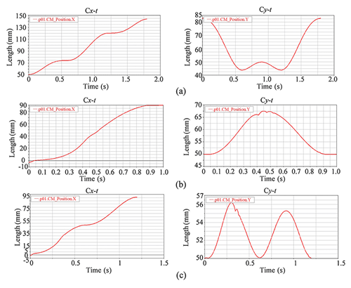
The contrast gait, speed gait, and steady gait processes have been simulated with the stipulation that 1t=0.01 s. This implies that the minimum time required to effect a 1° change in the drive angle is 0.01 s. The simulation curves for the horizontal (Cx−t) and vertical (Cy−t) displacements over time for the contrast gait, speed gait, and steady gait are depicted in Fig. 3.
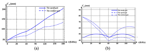
The comparative analysis of speed between the speed gait and the contrast gait is illustrated in Fig. 4a, where the speed gait accomplishes a forward step in 0.92 s, representing a 95 % increase in speed relative to the contrast gait. The graphical representations of the CM fluctuations for the steady, speed, and contrast gaits are presented in Fig. 4b. The CM volatility for the contrast gait stands at 43.3 %, and for the speed gait, it is 19.5 %. The steady gait demonstrates a 37.46 % reduction in CM volatility in comparison to the contrast gait and a 13.66 % reduction when compared to the speed gait.
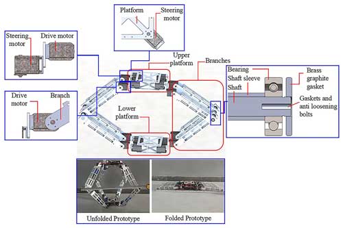
In order to verify the correctness of each gait design, a physical prototype verification method was also adopted. The prototype was crafted with precise adherence to the proportional dimensions depicted in simulation model. As shown in Fig. 5, the physical sample is mainly composed of an upper platform, a lower platform, and multiple branches connecting the two platforms. Both platforms are square, each corner of which is linked to a steering motor, facilitating directional adjustments of the branches and the overall steering capability of the mechanism. On this basis, the steering motors and the branches are connected by drive motors, achieving changes in the overall shape and mobility of the mechanism. The branch is divided into two parts, with two parts joined by a shaft rotation. To ensure smooth operation, components like shaft sleeves, bearings, and gaskets are integrated, promoting lubrication between the segments. This meticulous design approach guarantees the mechanical integrity and performance of the prototype.
Furthermore, Fig. 5 provides a detailed view of the prototype's design dimensions in two distinct configurations. In its unfolded state, the prototype spans a generous 550 mm by 550 mm by 600 mm, offering ample space for movement and operation. Conversely, when the prototype is compactly folded, its dimensions are a more manageable 950 mm by 240 mm by 110 mm, making it easy to transport and store.
This ingenious design not only allows for flexibility in use but also ensures that the prototype remains portable despite its functional complexity. The total mass of the prototype, which is a critical factor in its practical application, is meticulously measured and recorded at 7.30 kg. This weight is a testament to the balance between the prototype's robust construction and the need for it to be easily handled and maneuverable in various environments.
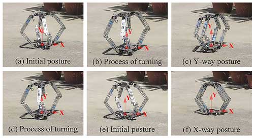
The video of the prototype is shown in the Supplement. The prototype is capable of transitioning from the initial posture to either the X-way or Y-way posture and can also make a direct transition from one posture to another. Figure 6a–c illustrate the prototype's progression from the initial posture to the Y-way posture, while Fig. 6d–f demonstrate the shift from the Y-way posture to the X-way posture. In the event of a recovery step, the prototype can revert to the initial posture from any of the intermediate postures.
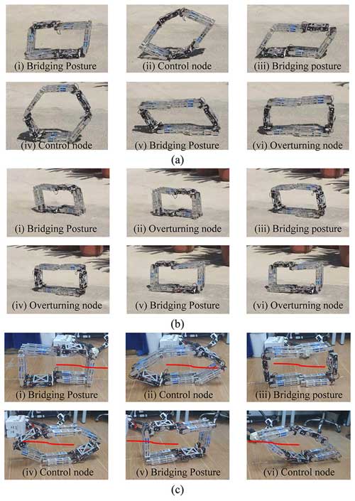
Figure 7 illustrates the experimental progression of the prototype advancing forward by 1000 mm using the contrast gait, speed gait, and steady gait. In this scenario, by executing three forward steps within a single period, the prototype achieves a movement speed of 0.1 m s−1 for the contrast gait, 0.25 m s−1 for the speed gait, and 0.125 m s−1 for the steady gait.
A novel 4–5R rolling mechanism, derived from a planar 6R single-loop kinematic chain, has been introduced. This mechanism leverages the integration and interconnection of multiple planar mechanisms to facilitate spatial steering capabilities. A comprehensive locomotion strategy suitable for flat ground has been proposed, and through the analysis of the contrast gait, key parameters such as speed and CM volatility have been determined. Subsequently, a faster speed gait and a more stable gait with reduced CM volatility have been successfully optimized. In conclusion, a prototype with spatial steering functionality has been designed, grounded in the aforementioned theories, and prototype experiments have been conducted to substantiate the validity of these concepts.
Looking ahead, future enhancements to the mechanism are slated in three key areas. Firstly, the optimization of collision forces during rolling locomotion will be addressed. Secondly, the analysis of the obstacle-crossing process will be expanded upon, utilizing the established locomotion strategy. Thirdly, the redesign of link shapes within the mechanism will be tailored to better suit specific application environments.
No data sets were used in this article.
The supplement related to this article is available online at: https://doi.org/10.5194/ms-15-633-2024-supplement.
QL was in charge of the whole trial; SK and ZP wrote the manuscript; QZ and JL provided guidance and discussion in theory; YeL and XW assisted with modeling and data analysis. YY and YuL assisted with image processing. All authors read and approved the final paper.
The contact author has declared that none of the authors has any competing interests.
Publisher's note: Copernicus Publications remains neutral with regard to jurisdictional claims made in the text, published maps, institutional affiliations, or any other geographical representation in this paper. While Copernicus Publications makes every effort to include appropriate place names, the final responsibility lies with the authors.
This work was supported by the National Natural Science Foundation of China (grant no. 52105006).
This research has been supported by the National Natural Science Foundation of China (grant no. 52105006).
This paper was edited by Zi Bin and reviewed by Mohammad Naeim Moradi and one anonymous referee.
Adams, I., Quinn, R. D., Lee, G., Kroeger, A., Thompson, R., and Feuerbacher, E.: Animal Acceptance of an Autonomous Pasture Sanitation Robot, Conference on Biomimetic and Biohybrid Systems, Springer International Publishing, Cham, 13548, 366–377, https://doi.org/10.1007/978-3-031-20470-8_36, 2022.
Bicchi, A. and Prattichizzo, D.: Manipulability of Cooperating Robots with Unactuated Joints and Closed-Chain Mechanisms, IEEE T. Robotic. Autom., 16, 336–345, https://doi.org/10.1109/70.864226, 2000.
Curtis, S., Brandt, M., Bowers, G., Brown, G., Cheung, C., Cooperider, C., Desch, M., Desch, N., Dorband, J., Gregory, K., Lee, K., Lunsford, A., Minetto, F., Truszkowski, W., Wesenberg, R., Vranish, J., Abrahantes, M., Clark, P., Capon, T., Weaker, M., Watson, R., Olivier, P., and Rilee, M. L.: Tetrahedral Robotics for Space Exploration, IEEE Aero. El. Sys. Mag., 22, 22–30, https://doi.org/10.1109/AERO.2007.352704, 2007.
Debruyn, D., Zufferey, R., Armanini, S. F., Winston, C., Farinha, A., Jin, Y., and Kovac, M.: MEDUSA: A Multi-Environment Dual-Robot for Underwater Sample Acquisition, IEEE Robot. Autom. Lett., 5, 4564–4571, https://doi.org/10.1109/LRA.2020.3001534, 2020.
Ghorbel, F. H., Chetelat, O., Gunawardana, R., and Longchamp, R.: Modeling and Set Point Control of Closed-Chain Mechanisms: Theory and Experiment, IEEE T. Contr. Syst. T., 8, 801–815, https://doi.org/10.1109/87.865853, 2000.
Guo, L. S. and Zhang, Q.: Adaptive trajectory control of a two DOF closed-chain robot, in: Proceedings of the 2001 American Control Conference (ACC), Arlington, VA, 25–27 June 2001, 658–663, https://doi.org/10.1109/ACC.2001.945622, 2001.
He, Y., Li, Y., Wu, J., Liu, X., and Yao, Y.: Design and Mobility Analysis of a Multi-mode Two-wheel Mobile Robot, J. Mech. Eng., 55, 83–92, https://doi.org/10.3901/JME.2019.23.083, 2019.
Hu, S., Liu, R., Li, R., Huang, T., Li, Y., and Yao, Y. A.: Design and analysis of a size-tunable tetrahedron rolling mechanism based on deployable RRR chains, Mech. Mach. Theory, 183, 105284, https://doi.org/10.1016/j.mechmachtheory.2023.105284, 2023.
Ivosevic, B., Han, Y.-G., Cho, Y., and Kwon, O.: The Use of Conservation Drones in Ecology and Wildlife Research, Journal of Ecology and Environment, 38, 113–118, https://doi.org/10.5141/ecoenv.2015.012, 2015.
Kim, S., Han, S. H., and Kim, D. H.: Analysis of a Crab Robot Based on Jansen Mechanism, in: 2011 11th International Conference on Control, Automation and Systems (ICCAS), Gyeonggi-do, South Korea, 26–29 October 2011, 858–860, ISBN 978-89-93215-03-8, 2011.
Kim, S., Hirota, K., Nozaki, T., and Murakami, T.: Human Motion Analysis and its Application to Walking Stabilization with COG and ZMP, IEEE T. Ind. Inform., 14, 5178–5186, https://doi.org/10.1109/TII.2018.2830341, 2018.
Li, Y., Yao, Y., Cheng, J., Tian, Y., and Liu, R.: An agile assistant robot integrating operation and rolling locomotion, Ind. Robot, 44, 114–126, https://doi.org/10.1108/IR-05-2016-0147, 2017.
Li, Y., Yao, Y., and He, Y.: Design and analysis of a multi-mode mobile robot based on a parallel mechanism with branch variation, Mech. Mach. Theory, 130, 276–300, https://doi.org/10.1016/j.mechmachtheory.2018.07.018, 2018.
Li, Y., Wang, Z., Xu, Y., Dai, J. S., Zhao, Z., and Yao, Y.: A Deformable Tetrahedron Rolling Mechanism (DTRM) Based on URU Branch, Mech. Mach. Theory, 153, 104000, https://doi.org/10.1016/j.mechmachtheory.2020.104000, 2020.
Mori, O. and Omata, T.: Coupling of Two 2-Link Robots with a Passive Joint for Reconfigurable Planar Parallel Robot, in: 2002 IEEE International Conference on Robotics and Automation, Washington, DC, USA, 11–15 May 2002, 4120–4125, https://doi.org/10.1109/ROBOT.2002.1014391, 2002.
Mortezapoor, S., Schönauer, C., Rüggeberg, J., and Kaufmann, H.: Photogrammabot: An Autonomous ROS-Based Mobile Photography Robot for Precise 3D Reconstruction and Mapping of Large Indoor Spaces for Mixed Reality, in: 2022 IEEE Conference on Virtual Reality and 3D User Interfaces (VRW 2022), Christchurch, New Zealand, 12–16 March 2022, 92–98, https://doi.org/10.1109/VRW55335.2022.00033, 2022.
Nguyen, H., Zhou, J., Kang, H., and Le, T.: Position Accuracy Improvement of Robots Having Closed-Chain Mechanisms, in: 10th International Conference on Intelligent Computing (ICIC), Taiyuan, China, 3–6 August 2014, 285–292, https://doi.org/10.1016/j.neucom.2014.03.085, 2014.
Nodehi, S. E., Bruzzone, L., and Fanghella, P.: SnakeTrack, A Bio-inspired, Single Track Mobile Robot with Compliant Vertebral Column for Surveillance and Inspection, in: International Conference on Robotics in Alpe-Adria Danube Region, Klagenfurt, Austria, 8–10 June 2022, 513–520, https://doi.org/10.1007/978-3-031-04870-8_60, 2022.
Park, S., Park, E., Yim, M., Kim, J., and Seo, T.: Optimization-Based Nonimpact Rolling Locomotion of a Variable Geometry Truss, IEEE Robot. Autom. Lett., 4, 747–752, https://doi.org/10.1109/LRA.2019.2892596, 2019.
Piovan, G. and Byl, K.: Reachability-Based Control for the Active SLIP Model, Int. J. Robot. Res., 34, 270–287, https://doi.org/10.1177/0278364914552112, 2015.
Pringle, S., Davies, Z. G., Goddard, M. A., Dallimer, M., Hart, E., Le Goff, L. E., and Langdale, S. J.: Robotics and Autonomous Systems for Environmental Sustainability: Monitoring Terrestrial Biodiversity, in: UKRAS White Papers, UKRAS, 17 October 2023, https://doi.org/10.31256/wp2023.4, 2023.
Ross, R., Carver, S., Browne, E., and Thai, B. S.: WomBot: an exploratory robot for monitoring wombat burrows, SN Appl. Sci., 3, 647, https://doi.org/10.1007/s42452-021-04595-4, 2021.
Saar, K. A., Rosendo, A., and Llda, F.: Bayesian Optimization of Gaits on a Bipedal SLIP Model, in: 2017 IEEE International Conference on Robotics and Biomimetics (ROBIO), Macau, Macao, 5–8 December 2017, 1812–1817, https://doi.org/10.1109/ROBIO.2017.8324681, 2017.
Stanley, J., Schroeder, A., and Trease, B.: Rolling Locomotion of Hexagonal Kinematic Chain Robot, International Design Engineering Technical Conferences and Computers and Information, in: Engineering Conference, American Society of Mechanical Engineers, St. Louis, Missouri, USA, 14–17 August 2022, V007T07A050, https://doi.org/10.1115/DETC2022-89978, 2022.
Szynkiewicz, W. and Blaszczyk, J.: Optimization-based approach to path planning for closed chain robot systems, Int. J. Appl. Math. Comp., 21, 659–670, https://doi.org/10.2478/v10006-011-0052-8, 2011.
Teng, X., Li, Y., Liu, Y., and Yao, Y.: Design and Reconfiguration Analysis of the Trunk Mechanism for a Reconfigurable Wheeled Mobile Platform, J. Mech. Robot., 16, 054505, https://doi.org/10.1115/1.4064740, 2024.
Tian, Y., Zhang, D., Yao, Y., Kong, X., and Li, Y.: A Reconfigurable Multi-Mode Mobile Parallel Robot, Mech. Mach. Theory, 111, 39–65, https://doi.org/10.1016/j.mechmachtheory.2017.01.003, 2017.
To, M. and Webb, P.: An Improved Kinematic Model for Calibration of Serial Robots Having Closed-Chain Mechanisms, Robotica, 30, 963–971, https://doi.org/10.1017/S0263574711001184, 2012.
Tzafestas, S. G.: Mobile Robot Control and Navigation: A Global Overview, J. Intell. Robot. Syst., 91, 35–58, https://doi.org/10.1007/s10846-018-0805-9, 2018.
Wang, Z., Li, Y., and Yao, Y.: Motion and Path Planning of a Novel Multi-Mode Mobile Parallel Robot Based on Chessboard-Shaped Grid Division, Ind. Robot, 45, 390–400, https://doi.org/10.1108/IR-01-2018-0001, 2018.
Yu, H., Gao, H., Ding, L., Li, M., Deng, Z., and Liu, G.: Gait Generation with Smooth Transition Using CPG-Based Locomotion Control for Hexapod Walking Robot, IEEE T. Ind. Electron., 63, 5488–5500, https://doi.org/10.1109/TIE.2016.2569489, 2016.
Zhang, D., Zheng, W., Yang, Y., and Fang, T.: CPG-Based Gait Control Method for Quadruped Robot Jumping Movement, in: 2021 7th International Conference on Control, Automation and Robotics (ICCAR), Singapore, 23–26 April 2021, 41–45, https://doi.org/10.1109/ICCAR52225.2021.9463469, 2021.
Zhang, Q., Li, Y., Wu, J., and Yao, Y.: Design and Analysis of a Hexagon Rolling Mechanism with a Center-Arranged Actuator, Mech. Mach. Theory, 174, 104910, https://doi.org/10.1016/j.mechmachtheory.2022.104910, 2022.
Zhao, Z., Li, Y., Wu, J., and Yao, Y.: Envelop-Climbing Locomotion Planning and Capability Analysis of a Deformable Tetrahedron Rolling Robot, IEEE Robot. Autom. Lett., 8, 4625–4632, https://doi.org/10.1109/LRA.2023.3284374, 2023.
Zi, P., Xu, K., Chen, J., Wang, C., Zhang, T., Luo, Y., Tian, Y.B., Wen, L., and Ding, X.: Intelligent Rock-Climbing Robot Capable of Multimodal Locomotion and Hybrid Bioinspired Attachment, Adv. Sci., 11, 39, https://doi.org/10.1002/advs.202309058, 2024.


