the Creative Commons Attribution 4.0 License.
the Creative Commons Attribution 4.0 License.
Anthropomorphic modular gripper finger actuated by antagonistic wire and shape-memory alloy (SMA) springs
Yiwen Lan
Binghao Wang
The traditional underactuated grippers can only passively adapt to the contour of the object, and the passive contact process may lead to the object slipping, affecting the stability of the grasping process. In this paper, an anthropomorphic modular gripper finger actuated by antagonistic wire and shape-memory alloy (SMA) springs, which can actively control the grasping morphology according to the characteristics of the objects to be grasped, is proposed. The wire drive simulates the flexor muscle, and the SMA and reset springs simulate the extensor muscles of the finger, which antagonistically control the grasping morphology of the finger. It is more in line with the grasping characteristics of the human hand. According to the moment equilibrium principle of the finger joints, the deformation model of the gripper is established, the influence of the wire tension and the equivalent stiffness of the finger joints on the grasping morphology is analyzed, and the theoretical joint angle results are verified by the Adams simulation; finally, the experimental system of the gripper is constructed, and the verification of the deformation morphology of the single finger and the gripper's enveloping–grasping experiments is completed. The results show that according to the contour size of the object, by actively controlling the wire force of the gripper and the equivalent stiffness of the interphalangeal joints, the enveloping–grasping action of different objects can be completed and the stable grasping of objects of different shapes and sizes can be realized.
- Article
(6760 KB) - Full-text XML
- BibTeX
- EndNote
Robots need to complete many grasping tasks in human production and life, and the gripper, which is the most direct and basic interaction between robots and the external environment, is one of the key execution parts, so the design and control of grippers that meet a variety of functional requirements have always been one of the hotspots of research in the field of robotics.
Fully actuated hands have the same number of motors as the number of degrees of freedom. Deshpande et al. (2013) constructed a 21-degree-of-freedom anatomically correct test bed (ACT) hand with a human-like tendon structure, and Yamano and Maeno (2005) designed a 20-degree-of-freedom Keio hand actuated by ultrasonic motors with elastic elements. Grebenstein et al. (2011) designed a 19-degree-of-freedom Deutsches Zentrum für Luft- und Raumfahrt (DLR) hand actuated by tendons. These fully actuated grippers have high grasping (the task where the gripper restricts the motion of an object; Hota and Kuma, 2019) and manipulation (also known as dexterous manipulation, the task where multiple fingers work in concert to manipulate an object; Okamura et al., 2000) capabilities, and more actuators are required to achieve these capabilities. Gripper grasping objects with complex morphology require multiple sensors to work in concert, thus increasing control cost and complexity.
To make the gripper better fit the object it is enveloping and, at the same time, increase the flexibility of the gripper, the soft gripper whose body is processed with soft or flexible materials has been further developed (Lee et al., 2017). Soft grippers can be classified into three categories according to the driving method: variable wire length drive, fluid variable pressure drive, and smart material deformation drive (Li et al., 2023). Dragusanu et al. (2022) proposed the DressGripper by which grasping is achieved through the synergy between the tendon and magnetic actuation, where the tendon transmits actuation force to the joints to control the flexion and extension of the fingers and the magnetic actuation is used to enhance the durability of the fingertip grip. Manti et al. (2015) proposed a soft bionic adaptive grasping hand whose main body is made of soft material and uses a wire actuation to change the degree of bending. Lee et al. (2020) designed the TWISTER Hand inspired by origami. The main part of the gripper is made of a twisted origami tower. The surface of the gripper is rigid, and the folded area is flexible, which is flexed by the wire actuation to achieve grasping. Sun et al. (2020) presented a TWISTER Hand inspired by pangolin scales, in which the gripper is driven to bend by changes in the air chamber through changes in air pressure and the stiffness of the gripper is altered by the bite of the teeth. Cui et al. (2021) proposed a pneumatic gripper with a continuously adjustable initial grasping state, in which the gripper consists of three actuators which control the distance of the gripper, the initial angle of the grasping, and the degree of bending, respectively. Ali et al. (2021) proposed a bionic hand based on a curved shape-memory alloy (SMA) similar to the human musculoskeletal system, with a three-segment finger structure consisting of six SMA actuators, and the joints between the knuckles are provided with actuation force through the SMAs to achieve the bending of the fingers and grasping of objects. Wang et al. (2020) proposed a variable bending soft finger based on SMA, with an embedded variable stiffness structure as the endoskeleton and a shape-memory polymer (SMP) as the heating element of the variable stiffness structure, and the bending of the gripper was realized by heating of the segmented SMP through multiple welding tabs. Liu et al. (2020) proposed a variable bending soft gripper based on SMA, where each finger of the gripper consists of a rigid component with variable stiffness joints. Soft grippers have the advantage of being able to generate deformations by the material's own or structural compliance, adapting to the contours of the shape of the grasping object (Cianchetti et al., 2015), and have a natural advantage in grasping unknown objects (Rus and Tolley, 2015), and, due to their deformable and pliable body structure, there is a high level of safety when interacting with the environment (Polygerinos et al., 2017; Laschi et al., 2016). However, soft grippers may suffer from weak load capacity, slow response time, pneumatic–hydraulic actuation requiring external equipment for power, high equipment cost, manufacturing and assembly loads, and airtightness (Sut and Sethuramalingam, 2023; Yin et al., 2020).
Underactuated grippers also have the characteristic of adapting the contours of an object, and wire actuation has been used in many underactuated grippers. Li et al. (2022) developed the BRL/Pisa/IIT SoftHand. Boisclair et al. (2021) proposed an underactuated hand structure based on rolling contact joints, where joints between the knuckles are connected by two sets of cords so that the joint surfaces are constrained to remain in contact and roll against each other without sliding, and the driving wires are wired through pulleys in the central layer of the phalanges to control finger flexion. Link-driven grippers can provide higher output force, reliable structure, and higher stiffness compared to wire-driven ones. Yoon and Choi (2017) proposed an underactuated hand consisting of a retractable slider-crank mechanism and a stackable four-bar mechanism with 3 degrees of freedom for each finger; the slider-crank mechanism is connected to a four-link mechanism that forms the phalanx of the finger bone with linear springs, and the through-slider-crank mechanism is used to transfer the driving force to the linkage part, which is capable of natural movement as well as adaptive grasping. Zhao et al. (2022) proposed an underactuated three-finger gripper for extreme environments capable of grasping, pressing, and pinching, with linkage-driven fingers and double-layer gearing in the palm section to shorten the transmission chain and improve the spatial layout. Liu et al. (2020) designed an underactuated gripper without parasitic rotation, where the underactuated fingers can use two parallelograms connected in a series to ensure full horizontal movement of the fingertips. Tamamoto et al. (2013) proposed a 7-degree-of-freedom underactuated hand that consists of a single motor controlling a series of gearing systems, which can be used to grasp and pinch using an adaptive envelope to grasp objects and has a variable stiffness mechanism (VSM) to adjust the joint stiffness. Compared with traditional universal grippers and fully actuated grippers, underactuated grippers have fewer driving parts, simpler structure, easier control, better gripping performance, and certain operability. However, underactuated grippers can only passively adapt to the shape profile of the object to complete the enveloping action when gripping the object, which may cause the object to slide down during the passive contact process and affect the stability of the gripping process. To solve the problem of traditional underactuated grippers only being able passively adapt to the shape of the grasping object, this paper proposes a modular gripper finger based on a wire–SMA spring differential drive based on the structural advantages of underactuated fingers.
First, the structure of the gripper is described according to the physiological structure of the human finger, and its deformation principle is analyzed. Then, the deformation model of the single finger is established, and its correctness is verified by an Adams simulation. Finally, the deformation morphology of the single finger and the gripper's enveloping–grasping experiments are completed, demonstrating the morphing and enveloping–grasping capabilities of the gripper.
2.1 Physiological structure of human fingers
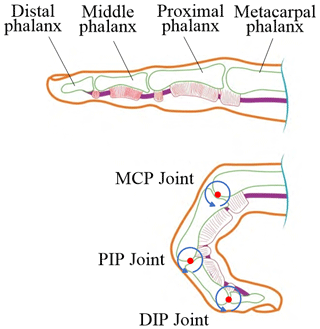
The human finger consists of three main parts: the bones, the bony connections, and the skeletal muscles. The bones mainly play a supporting role, the bony connections are the pivot of finger movement, and the skeletal muscles provide the driving force for finger movement. The bones of the finger are the metacarpal bone, proximal phalanx, middle phalanx, and distal phalanx. The finger bone and joint structure of the human hand are the basis of movement, the interphalangeal joint consists of the distal interphalangeal (DIP) joint, the proximal interphalangeal (PIP) joint, and the metacarpophalangeal (MCP) joint, as shown in Fig. 1.
In humans, when approaching and grasping an object with the hand, the fingers are usually flexed into a geometric shape that fits the contour of the object being grasped, improving the stability of the grasp. Tendons enable contraction and extension movements of the fingers, and tendons attach to the phalanges to transmit driving forces. The flexor tendon connects to the inner side of each phalanx, and the contraction of the flexor muscle drives the flexor tendon connecting to each knuckle, causing the finger to bend and deform. When the extensor muscle contracts, the extensor tendon, which is attached to the dorsal surface of the phalanx, moves so that the finger can be straightened. The force of finger flexion and extension is controlled by the contraction strength of the tendon, and the interplay between the flexor and extensor muscles enables the fingers to form a target posture so that the fingers bend into a suitable hand shape according to the shape and size of the object before grasping the object, as shown in Fig. 2.
2.2 Structure of the anthropomorphic gripper
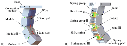
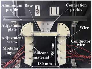
Concerning the physiological structure of human fingers, a modular gripper finger based on a differential drive of a wire and SMA springs is proposed. The finger is mainly composed of a base, connection module, finger modules, driving wire, SMA springs, silicone material, etc. The finger structure is shown in Fig. 3a. A single finger consists of four modules, which are connected into rotating joints by rotating shafts. One end of the wire is connected to the motor to generate driving force and control the morphology of the gripper, and the other end of the wire passes through the guiding holes of the connecting modules, module I and module II in turn, and is connected to module III. The wire connects the modules, transmits the driving force, and acts as a flexor tendon. The surface of the finger contacting the object is installed with a soft silicone material, which is used to ease the contact impact, increase friction, and improve the safety and stability of grasping.
The outer side of the finger module consists of a spring group consisting of multiple SMA springs and reset springs to simulate the extensor tendon, as shown in Fig. 3b. The SMA springs are simple in structure, small in size, light in mass, and high in energy density, and the equivalent stiffness of the spring can be adjusted by varying the energizing current of the SMA springs (Ma et al., 2013; Lee et al., 2019). The two ends of the spring are connected to the spring mounting plate by fasteners, respectively, and the mounting plate is embedded in the groove inside the module and fixed. The function of the reset springs is to keep the finger in the initial closed state when it is not grasping an object as well as to reset the finger to the initial state after the end of grasping. The wire is used to control the bending and extension of the fingers in concert with the spring group, thus achieving the purpose of controlling the grasping morphology of the fingers.
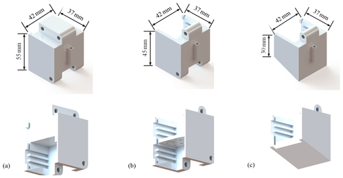
The design of modular joints should consider not only the compactness of the structure but also the mounting space inside the module, which is used to embed the mounting spring group. To ensure that the strength of the finger module is not reduced due to the hollow interior design, ribs and other plates are designed as supports inside the module. Three sets of symmetrically arranged grooves are designed on the inner wall of the module at equal intervals, and the initial stiffness of the spring pack can be adjusted by changing the mounting position of the spring retainer plate in the internal grooves or selecting the appropriate position of the spring retainer plate according to the spring dimensions and the initial length requirements. The internal structure of the modular joint and the dimensions of the module profile are shown in Fig. 4.
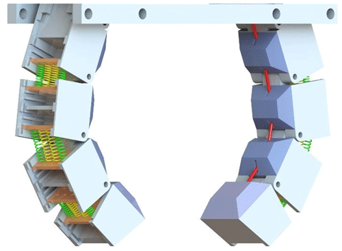
In this paper, the gripper adopts the symmetrical arrangement of two fingers, and the knuckle is formed by three modules in a series and connected to the base through the connection module. The silicone cushioning material inside the fingers is designed to be a trapezoidal shape to avoid mutual contact and collision of the silicone material during joint movement. The overall structure of the gripper is shown in Fig. 5. The advantage of structural modularity is that the envelope can be expanded by changing the number of modules connected in a series, and the adjustment is simple. Adjusting the angle between the base and the connecting modules can also adjust the envelope of the gripper to adapt to the gripping of objects of more sizes and shapes.
3.1 Deformation principles
The SMA spring works through the principle of electrothermal actuation, where the power supply connects to the SMA spring and outputs a current, the temperature of the SMA spring increases to induce a martensitic phase transition, and the stiffness of the SMA spring starts to produce changes. The stiffness of the SMA spring when it is completely in the parent phase (austenite phase) is used as a parameter to establish the mechanical model, and, currently, the stiffness of the SMA spring, KS, is constant.
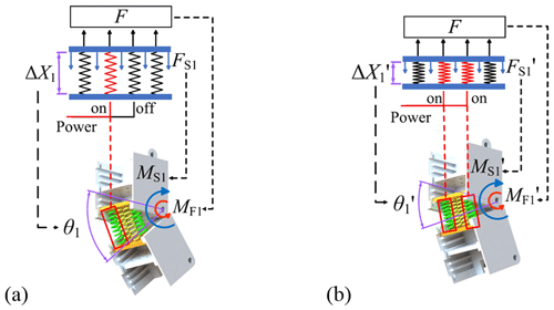
The principle of inter-module angle variation is shown in Fig. 6. When the power supply energizes one group of SMA springs, the spring group length is stretched by ΔX1 under tension F, and the total spring force of the spring group is FS1; when the power supply energizes two groups of SMA springs, the spring group length is stretched by under tension F, and the total spring force of the spring group is . This different elongation of the spring group makes the finger act as when the power supply energizes one group of SMA springs, the torque produced by tension force F at the joint is MF1, and the total torque produced by the spring group at the joint is MS1, at which time the angular displacement of the joint is θ1; the power supply energizes the two groups of SMA springs, the torque produced by tension force F at the joint is , and the total torque produced by the spring group at the joint is , at which time the angular displacement of the joint is . The change in the rotation angle of the joint can be achieved by changing the equivalent stiffness of the spring group, while the tension force remains unchanged. When multiple modules are connected in a series, the grasping morphology of the fingers can be controlled by changing the number of energized SMA springs in each joint together with the driving force of the wire. The differential drive between the wire and the SMA springs allows the finger to choose from a variety of gripping morphologies and to change its gripping morphology according to the contours of the object to be gripped, increasing the stability of the gripping.
3.2 Deformation model of the finger
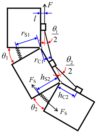
In this paper, a single finger is taken as the research object, and the mechanical model of the finger is established, as shown in Fig. 7. When the sum moment of the wire driving force and the spring group tension at the joint is 0, the finger reaches a stable grasping state, which can be expressed as follows:
where MFi is the driving moment generated by the wire driving force on joint i, MSi is the resisting moment generated by the whole spring group portion on joint i, and i is the joint number.
The moment of the wire drive, MFi, can be expressed as follows:
where F is the wire driving force and rCi is the force arm of the wire force on the rotational axis of joint i. rCi can be expressed as follows:
where l is the distance from the point of action of the wire force to the end face, hCi is the distance from the point of action of the wire force to the rotational axis of joint i, and θi is the rotation angle of the ith joint.
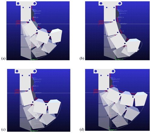
Figure 9(a) Morphology I (). (b) Morphology II (n1=1.5 n2=1.5 n3=1). (c) Morphology III (n1=1.5 n2=1 n3=1.5). (d) Morphology IV (n1=1 n2=1.5 n3=1.5).
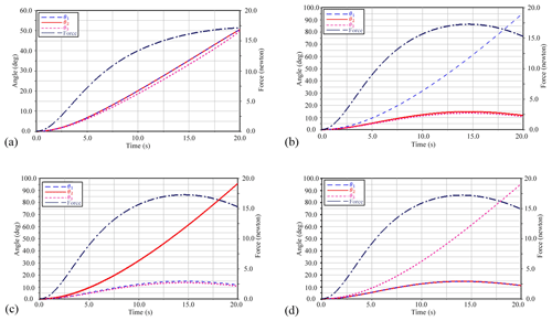
Figure 10Adams simulation results. (a) Morphology I (). (b) Morphology II (n1=1.5 n2=1.5 n3=1). (c) Morphology III (n1=1.5 n2=1 n3=1.5). (d) Morphology IV (n1=1 n2=1.5 n3=1.5).
The resistance moment MSi of the spring group to the joint can be expressed as follows:
where FSi is the total tension in the spring group of joint i and rSi is the force arm of the spring group against the joint rotational axis. FSi and rSi can be expressed as follows:
where hSi is the distance from the spring group force action point to the rotational axis of joint i, λ is the number of reset springs, K is the stiffness coefficient of the reset springs, KS is the equivalent stiffness of a single SMA spring when it is completely in the parent phase, KSi is the equivalent stiffness of the SMA spring energized at joint i, and ni is the stiffness equivalence coefficient of the SMA spring at joint i. ni can be expressed as follows:
Substituting Eqs. (2)–(7) into Eq. (1) yields the relationship between the wire driving force, the spring group stiffness equivalence coefficient, and the joint angle of rotation, which can be expressed as follows:
The SMA spring is the main part to change the stiffness of the gripper finger, and each SMA spring is controlled by a separate current channel. After the SMA spring is connected to the power supply, according to Joule's law (Q=I2Rt), the temperature of the spring increases with the increase in the energization time, and when it reaches the temperature of the phase transition, the internal structure of the SMA spring is changed from martensite to austenite (Case et al., 2018), and the SMA spring shrinks on its own to generate contraction force. de Sousa et al. (2018) gave a relationship for the calculation of the SMA spring stiffness, which can be expressed as follows:
where ξ denotes stress-induced martensite fraction, G(ξ) denotes the modulus of elasticity associated with martensite fraction, F denotes the axial force of the spring, y denotes the axial deflection of the spring, r denotes the wire diameter of the spring, R denotes the average diameter of the spring, and N denotes the effective number of turns of the spring.
where D(ξ) denotes the shear modulus associated with the martensite fraction and μp denotes Poisson's ratio of the spring.
ξ can be expressed as follows:
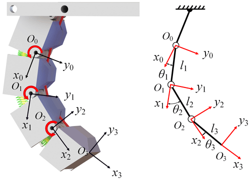
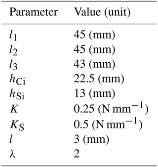
where ξ0 denotes the martensite fraction under complete austenite, and the subscript indicates the reference state, Af denotes austenite termination temperature, AS denotes the initial austenite temperature, T denotes temperature, CA denotes the martensite–austenite transformation constant, and σ denotes normal stress. The parametric modeling of finger links is shown in Fig. 8, and the parameters of the fingers in the paper are shown in Table 1.
The coordinate transformation matrix, nTn+1, between two neighboring modules of the finger can be expressed as follows:
where θ represents the angle of rotation around the z axis, d is the distance (or joint offset) between the fingertips of two neighboring common pendants on the z axis, a represents the length of each common plumb line (linkage length), and α represents the angle (or torsion angle) between two neighboring z-axis fingertips.
Since the finger moves only in the XY plane, both d and α take the value of 0. The resulting position computation matrix of the end of the finger concerning the base coordinate system can be expressed as follows:
The coordinates of the fingertip O3 in the base coordinate system, (Ox, Oy, Oz), can be expressed as follows:
where S1 denotes sinθ1, C1 denotes cosθ1, S123 is an abbreviation for sin(), and C123 is an abbreviation for cos().
The stiffness of the springs selected for the prototype is experimentally measured, and the stiffness of the reset spring and the SMA spring in the experiment is about 0.25 (N mm−1) and 0.5 (N mm−1), respectively. Therefore, the equivalent stiffness of a single-reset spring is set to K=0.25 (N mm−1), the stiffness of the SMA spring is set to KS=0.5 (N mm−1) in the simulation, and the equivalent stiffness of each joint spring group is Ki. Four groups of grasping morphologies with different stiffness equivalence coefficients are selected for simulation, and the corresponding stiffness equivalence coefficients of the grasping morphologies with the joint equivalent stiffness parameters are shown in Table 2.
The simulation process of a single-finger grasping morphology is shown in Fig. 9, and the relationship between the corresponding driving force and angle with time during the change in single-finger grasping morphology is shown in Fig. 10. In the simulation, the finger is first in the initial closed state, and the finger starts to bend and deform under the wire drive. The equivalent stiffness of the joint spring group is different, and the size of the inter-module tension angle is also different, forming different initial grasping postures. From the initial closed state to the end of the movement, there is a corresponding fingertip-end movement trajectory line. From the movement trajectory in the figure, it can be seen that the smaller the joint stiffness near the connection module, the greater the degree of flexural deformation of the finger and the greater the range of movement of the fingertip, which is suitable for enveloping large-sized objects; the greater the joint stiffness near the connection module, the smaller the degree of flexural deformation of the finger as a whole, and the form can transfer the driving force of the rope to the fingertip with a higher transfer efficiency to make the fingertip produce a greater clamping force, which is suitable for clamping smaller-sized objects.
The driving force and the angles are simulated, and the simulation results are shown in Fig. 10. For morphology I (), the angles θ1, θ2, and θ3 reach about 50°. For the morphology II (n1=1.5, n2=1.5, n3=1), angle θ1 reaches about 94°, and angles θ2 and θ3 reach about 12°. For morphology III (n1=1.5, n2=1, n3=1.5), angles θ1 and θ3 reach about 12°, and angle θ2 reaches about 95°. For morphology IV (n1=1, n2=1.5, n3=1.5), angles θ1 and θ2 reach about 12°, and angle θ3 reaches about 94°. The theoretical deformation angles are also calculated based on Eq. (8). The theoretical and the Adams simulation results of the joint angles are presented in Table 3. The joint angles calculated by the simulation are consistent with the theoretical calculation results, which verifies the correctness of the deformation model. The rotation angles of the joints with the same equivalent stiffness of the spring group change almost in the same way over time, indicating that the tensile deflection effect produced by the wire driving force on the joints with the same equivalent stiffness is almost the same and so that the change of the joint angle is also basically the same. From the simulation results, it can also be obtained that the angle of the joints with larger joint equivalent stiffness will change from large to small after the driving force reaches a certain value, while the joints with smaller joint equivalent stiffness will increase all the time with the change in the driving force.
5.1 Mechanical system construction
The overall frame of the mechanical system is built with 3030 European standard aluminum profiles, and the guiding pulley installed on the profile frame is used to guide the driving wire. The gripper module is 3D-printed using 9400 resin material; meanwhile, the internal spring fixing plate of the module is 3D-printed and made with high-temperature-resistant resin material, which has high resistance to thermal deformation and can effectively avoid the higher temperature of the SMA spring from damaging the spacer. The gripper consists of a base, modular knuckles, ropes, cushioning silicone, SMA springs, reset springs, and energized cables. The built mechanical system is shown in Fig. 11. The mounting distance of the two fingers is about 180 mm, and the length of a single finger is about 190 mm. Therefore, the gripper in the experiment can grasp objects with a width of less than 180 mm.
5.2 Control system construction
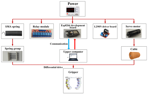
The control system is used to achieve motor and SMA spring control; the control system to make the robot complete the grasping task is shown in Fig. 12. The control system is constructed based on the ESP8266 development board; ESP8266 can be achieved through not only the self-contained Wi-Fi module to achieve communication but also the PC as a host computer connected to achieve communication. ESP8266 development board through the L298N motor drive module to control the motor to drive the wire by adjusting the pulse width modulation (PWM) of the motor can change the rate of change of the wire stroke to change the speed of the grasping movement. The signal output from the relay can control the on–off of the SMA spring power supply circuit to adjust the stiffness of the spring group.
5.3 Deformation experiment of a single finger
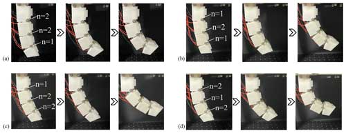
The innovation in this paper lies in the controllable grasping morphology of the gripper finger, which can be adjusted according to the shape and contour of the gripped object. Figure 13 shows the process of morphological changes in a single finger under the action of four groups of spring parameters. Because the equivalent stiffness of the spring groups is different, the angles of joints are different. The experimental results illustrate that the deformation of a single finger is actively controllable by controlling the equivalent stiffness of the spring group to regulate the size of the joint angles, which in turn controls the envelope morphology of the gripper finger.
5.4 Robotic grasping experiment
The grasping experiments are designed based on the above research on the bending morphology of the gripper fingers. The experimental steps are as follows: (1) place the selected object on the support platform directly under the gripper. (2) Determine the shape and size of the grasping object, adjust the height of the gripper so that it is at a suitable distance from the grasping object, and determine the number of energized SMA spring groups. (3) Energize the SMA spring through the power supply until the phase transition state of the SMA spring reaches a stable state and then control the force of the wire, which transmits the driving force to make the finger bending. (4) The finger bends into a reasonable form to contact the object and then envelops the object to maintain a stationary state. (5) Withdraw the support platform and keep the gripper grasping state unchanged and observe whether the object slips off. The grasping objects are selected from more typical cylindrical structures, ellipsoidal columns, rectangular bodies, and irregular objects. The radius of the cylindrical barrel in Fig. 14a is 56 mm, and the height is 130 mm; the length, width, and height of the rectangular body in Fig. 14b are 96, 65, and 137 mm, respectively. The highest position of the fan in Fig. 14c is 165 mm, and the longest length is 135 mm, the width of the fan disk position is 150 mm, and the width of the base is 70 mm.
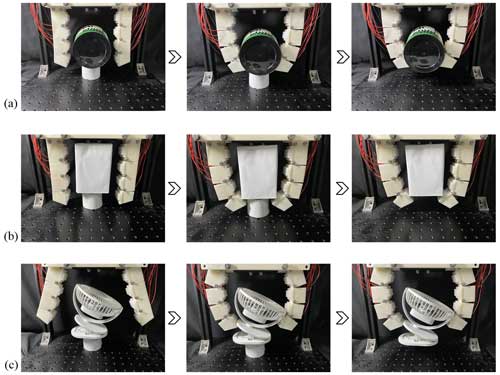
Figure 14(a) Grasping cylindrical barrel. (b) Grasping rectangular box. (c) Grasping irregular objects.
The enveloping–grasping experiments show that the gripper designed in this paper can be actively controlled according to the shape and size of the object to produce different degrees of deflection deformation and choose the appropriate grasping morphology. In the face of larger and heavier objects, the appropriate grasping form can be constructed to envelop the object rather than grasp it using the underactuated structure of the passive adaptive envelope object, which can improve the flexibility and stability of the gripper grasping the object.
To better imitate the grasping function of human fingers, based on retaining the structural advantages of underactuated fingers, a wire–SMA spring differential drive gripper is proposed which can adjust the wire driving force and the equivalent stiffness of the spring group according to the shape characteristics of the grasping object, actively change the grasping morphology of the gripper, and improve the grasping stability. Using Adams to simulate the finger enveloping morphology of four groups of different spring parameters, the equivalent stiffness of the spring group between the modules directly affects the size of the module's tensor angle; the smaller the equivalent stiffness of the spring group close to the root of the finger, the larger the range of motion between them, which is suitable for enveloping large-sized objects, and the larger the equivalent stiffness of the spring group close to the root of the finger, the easier the wire driving force is to be transferred to the end of the finger, which is suitable for grasping objects with smaller enveloping sizes.
In the process of enveloping–grasping typical-shaped objects, the robot fingers can actively control the grasping morphology and stably grasp objects of various shapes and sizes with high adaptability and reliability. Therefore, the grasping ability of the gripper to actively adjust the grasping morphology according to the shape characteristics of the target object is verified through the experiment. This is influenced by the heat dissipation efficiency of the SMA spring, resulting in the need to wait for the SMA spring to recover from cooling before constructing another grasping morphology when the gripper performs the grasping function, which affects the grasping efficiency of the gripper, and the heat dissipation efficiency of the SMA spring is to be improved in subsequent work.
All the data used in this paper can be obtained upon request from the corresponding author.
LS conceived the idea, developed the method, and wrote the majority of the paper. YL and BW assisted with the simulation and the experiment. All the authors read and approved the final paper.
The contact author has declared that none of the authors has any competing interests.
Publisher’s note: Copernicus Publications remains neutral with regard to jurisdictional claims made in the text, published maps, institutional affiliations, or any other geographical representation in this paper. While Copernicus Publications makes every effort to include appropriate place names, the final responsibility lies with the authors.
The authors would like to thank Xiaonan Bai and He Zhao for their help with the writing and experiment.
This paper was edited by Zi Bin and reviewed by three anonymous referees.
The authors have been supported financially by the Liaoning Education Department General Project (grant no. JYTMS20230200) and the Liaoning Doctor Scientific Research Initial Fund (grant no. 2021-BS-160).
Ali, H. F. M., Khan, A. M., Baek, H., Shin, B., and Kim, Y.: Modeling and Control of a Finger-like Mechanism using Bending Shape Memory Alloys, Microsyst. Technol., 27, 2481–2492, https://doi.org/10.1007/s00542-020-05166-0, 2021.
Boisclair, J. M., Laliberté, T., and Gosselin, C.: On the optimal design of underactuated fingers using rolling contact joints, IEEE Robot. Autom. Let., 6, 4656–4663, https://doi.org/10.1109/LRA.2021.3068976, 2021.
Case, J. C., White, E. L., SunSpiral, V., and Kramer-Bottiglio, R.: Reducing Actuator Requirements in Continuum Robots Through Optimized Cable Routing, Soft Robot., 5, 109–118, https://doi.org/10.1089/soro.2017.0030, 2018.
Chappell, D., Bello, F., Kormushev, P., and Rojas, N.: The Hydra Hand: A Mode-Switching Underactuated Gripper with Precision and Power Grasping Modes, IEEE Robot. Autom. Let., 8, 7599–7606, https://doi.org/10.1109/LRA.2023.3320897, 2023.
Cianchetti, M., Calisti, M., Margheri, L., Kuba, M., and Laschi, C.: Bioinspired locomotion and grasping in water: the soft eight-arm OCTOPUS robot, Bioinspir. Biomim., 10, 035003, https://doi.org/10.1088/1748-3190/10/3/035003, 2015.
Cui, Y. F., Liu, X. J., Dong, X. g., Zhou, J. Y., and Zhao, H. C.: Enhancing the Universality of a Pneumatic Gripper Via Continuously Adjustable Initial Grasp Postures, IEEE T. Robot., 37, 1604–1618, https://doi.org/10.1109/TRO.2021.3060969, 2021.
Deshpande, A. D., Xu, Z., Vande Weghe, M. J., Brown, B. H., Ko, J., Chang, L.Y., Wilkinson, D.D., Bidic, S.M., and Matsuoka, Y.: Mechanisms of the Anatomically Correct Testbed Hand, IEEE-ASME T. Mech., 18, 238–250, https://doi.org/10.1109/TMECH.2011.2166801, 2013.
de Sousa, V. C., De Marqui, C., and Elahinia, M. H.: Effect of constitutive model parameters on the aeroelastic behavior of an airfoil with shape memory alloy springs, J. Vib. Control., 24, 1065–1085, https://doi.org/10.1177/1077546316657501, 2018.
Dragusanu, M., Marullo, S., Malvezzi, M., Achilli, G. M., Valigi, M. C., Prattichizzo, D., and Salvietti, G.: The DressGripper: A Collaborative Gripper With Electromagnetic Fingertips for Dressing Assistance, IEEE Robot. Autom. Let., 7, 7479–7496, https://doi.org/10.1109/LRA.2022.3183756, 2022.
Grebenstein, M., Albu-Schäffer, A., Bahls, T., Chalon, M., Eiberger, O., Friedl, W., Gruber, R., Haddadin, S., Hagn, U., Haslinger, R., Höppner, H., Jörg, S., Nickl, M., Nothhelfer, A., Petit, F., Reill, J., Seitz, N., Wimböck, T., and Hirzinger, G.: The DLR Hand Arm System, in: IEEE International Conference on Robotics and Automation, Shanghai, China, 5980371, May, 2011, Institute of Electrical and Electronics Engineers Inc., United States, https://doi.org/10.1109/ICRA.2011.5980371, 2011.
Hota, R. K. and Kumar, C. S.: Effect of hand design and object size on the workspace of three-fingered hands, Mech. Mach. Theory, 133, 311–328, https://doi.org/10.1016/j.mechmachtheory.2018.11.011, 2019.
Laschi, C., Mazzolai, B., and Cianchetti, M.: Soft robotics: Technologies and systems pushing the boundaries of robot abilities, Sci. Robot., 1, eaah3690, https://doi.org/10.1126/scirobotics.aah3690, 2016.
Lee, C., Kim, M., Kim, Y. J., Hong, N., Ryu, S., Kim, H. J., and Kim, S.: Soft Robot Review, Int. J. Control Autom., 15, 3–15, https://doi.org/10.1007/s12555-016-0462-3, 2017.
Lee, J. H., Chung, Y. S., and Rodrigue, H.: Application of SMA spring tendons for improved grasping performance, Smart Mater. Struct., 28, 035006, https://doi.org/10.1088/1361-665X/aaf5f4, 2019.
Lee, K., Wang, Y. Z., and Zheng, C. Q.: Twister Hand: Underactuated Robotic Gripper Inspired by Origami Twisted Tower, IEEE T. Robot., 36, 488–500, https://doi.org/10.1109/TRO.2019.2956870, 2020.
Li, H. R., Ford, C. J., Bianchi, M., Catalano, M. G., Psomopoulou, E., and Lepora, N. F.: BRL/Pisa/IIT softhand: A low-cost, 3D-printed, underactuated, tendon-driven hand with soft and adaptive synergies, IEEE Robot. Autom. Let., 7, 8745–8751, https://doi.org/10.1109/LRA.2022.3187876, 2022.
Li, W. D., Hu, D. A., and Yang, L.: Actuation Mechanisms and Applications for Soft Robots: A Comprehensive Review, Appl. Sci.-Basel, 13, 9255, https://doi.org/10.3390/app13169255, 2023.
Liu, H., Zhao, L. H., Siciliano, B., and Ficuciello, F.: Modeling, optimization, and experimentation of the paragripper for in-hand manipulation without parasitic rotation, IEEE Robot. Autom. Let., 5, 3011–3018, https://doi.org/10.1109/LRA.2020.2974419, 2020.
Liu, M. F., Hao, L. N., Zhang, W., and Zhao, Z. R.: A novel design of shape-memory alloy-based soft robotic gripper with variable stiffness, Int. J. Adv. Robot. Syst., 17, 1729881420907813, https://doi.org/10.1177/1729881420907813, 2020.
Ma, J. Z., Huang, H. L., and Huang, J.: Characteristics Analysis and Testing of SMA Spring Actuator, Adv. Mater. Sci. Eng., 2013, 823594, https://doi.org/10.1155/2013/823594, 2013.
Manti, M., Hassan, T., Passetti, G., D'Elia, N., Laschi, C., and Cianchetti, M.: A Bioinspired Soft Robotic Gripper for Adaptable and Effective Grasping, Soft Robot., 2, 107–116, https://doi.org/10.1089/soro.2015.0009, 2015.
Okamura, A. M., Smaby, N., and Cutkosky, M. R.: An Overview of Dexterous Manipulator, in: IEEE International Conference on Robotics and Automation, San Francisco, USA, 255–262 pp., April,2000, IEEE, https://doi.org/10.1109/ROBOT.2000.844067, 2000.
Polygerinos, P., Correll, N., Morin, S. A., Mosadegh, B., Onal, C. D., Petersen, K., Cianchetti, M., Tolley, M. T., and Shepherd, R. F.: Soft robotics: Review of fluid-driven intrinsically soft devices; manufacturing, sensing, control, and applications in human-robot interaction, Adv. Eng. Mater., 19, 1700016, https://doi.org/10.1002/adem.201700016, 2017.
Rus, D. and Tolley, M. T.: Design, fabrication and control of soft robots, Nature, 521, 467–475, https://doi.org/10.1038/nature14543, 2015.
Sun, T., Chen, Y. L., Han T. Y., Jiao, C. L., Lian, B. B., and Song, Y. M.: A Soft Gripper with Variable Stiffness Inspired by Pangolin Scales, Toothed Pneumatic Actuator and Autonomous Controller, Robot. Cim-Int. Manuf., 61, 101848, https://doi.org/10.1016/j.rcim.2019.101848, 2020.
Sut, D. J. and Sethuramalingam, P.: Soft Manipulator for Soft Robotic Applications: a Review, J. Intell. Robot. Syst., 108, 10, https://doi.org/10.1007/s10846-023-01877-4, 2023.
Tamamoto, T. and Koganezawa, K.: Multi-joint gripper with differential gear chain, in: 2013 IEEE International Conference on Mechatronics and Automation, Takamastu, Japan, 4–7 August 2013, IEEE Computer Society, 6617889, https://doi.org/10.1109/ICMA.2013.6617889, 2013.
Wang, W., Yu, C. Y., Serrano, P. A. A., and Ahn, S. H.: Shape memory alloy-based soft finger with changeable bending length using targeted variable stiffness, Soft Robot., 7, 283–291, https://doi.org/10.1089/soro.2018.0166, 2020.
Yamano, I. and Maeno, T.: Five-finger Robot Hand Using Ultrasonic Motors and Elastic Elements, in: IEEE International Conference on Robotics and Automation, Barcelona, Spain, 2673–2678, April, 2005, IEEE, https://doi.org/10.1109/ROBOT.2005.1570517, 2005.
Yin, H.B., Tian, L., and Yang, G. L.: Design of fibre array muscle for soft finger with variable stiffness based on nylon and shape memory alloy, Adv. Robot., 34, 599–609, https://doi.org/10.1080/01691864.2020.1738272, 2020.
Yoon, D. and Choi, Y. J.: Underactuated finger mechanism using contractible slider-cranks and stackable four-bar linkages, IEEE-Asme T. Mech., 22, 2046–2057, https://doi.org/10.1109/TMECH.2017.2723718, 2017.
Zhao, C., Liu, M. H., Li, H., Jiang, Z. H., Feng, S. Y., Zheng, T., and Zhang, B. B.: Underactuated Three-finger Dexterous Hand in High Altitude and Extreme Environments, in: 2022 IEEE International Conference on Real-time Computing and Robotics (RCAR), Guiyang, China, 17–22 July 2022, Institute of Electrical and Electronics Engineers Inc., 20223912809279, https://doi.org/10.1109/RCAR54675.2022.9872216, 2022.


