the Creative Commons Attribution 4.0 License.
the Creative Commons Attribution 4.0 License.
 | 08 Oct 2024
A linkage-type self-adaptive deformable tracked mechanism based on the six-bar mechanism
Kaisheng Zhang
Xuemin Sun
Ruiming Li
Zhiguo Yu
Biao Yu
In order to design a self-adaptive tracked mechanism that can passively adjust according to the height of different obstacles to improve its obstacle-crossing performance, this paper proposes a linkage-type self-adaptive deformable tracked mechanism. The mechanism based on the planar six-bar mechanism is proposed, and its motion modes and obstacle-crossing capabilities are analyzed. Firstly, based on the characteristics of self-adaptive deformation and the planar six-bar mechanism, a deformable single-degree-of-freedom (DOF) multi-loop mechanism is designed by limiting the DOF and adjusting the link lengths, and subsequently, a linkage-type self-adaptive deformable tracked mechanism module is designed according to the multi-loop mechanism. Secondly, the movement characteristics of the deformable tracked mechanism module are analyzed, and it is obtained that the tracked mechanism has two modes of movement: forward and reverse. These modes include deformable tracked-type obstacle crossing and rocker-arm-type obstacle crossing, respectively. Additionally, it is also obtained that this mechanism is capable of climbing up and descending down slopes. Finally, a prototype model is designed for experimental verification to verify the correctness of the theoretical analysis of the linkage-type self-adaptive deformable tracked mechanism and the feasibility of the obstacle-crossing modes. The results indicate that the linkage-type self-adaptive deformable tracked mechanism is capable of various obstacle-crossing modes, including both forward and reverse movements. These modes encompass the traditional tracked type, the deformable tracked type, and the rocker-arm type, as well as the ability to climb up and descend down slopes. This type of mechanism demonstrates excellent terrain adaptability and is capable of overcoming obstacles, allowing it to traverse some soft and rugged terrain. Consequently, it holds certain application potential.
- Article
(11635 KB) - Full-text XML
-
Supplement
(48604 KB) - BibTeX
- EndNote


Mobile robotics is a key application field of robotics which emphasizes the characteristics of “mobility”. The mobile performance directly determines the working and survivability of the robot, and the mobile performance is largely determined by the design of the robot's mobile mechanism. As a result, the development of mobile mechanisms has emerged as a crucial research area and a pivotal technology within the field of mobile robotics. For the traditional ground mobile robots, it can be divided into wheeled robots, tracked robots, and legged robots according to their movement modes, each with its own characteristic and suitable terrain. The wheeled mobile robot excels in speed on flat terrain, the legged mobile robot demonstrates robust obstacle-climbing capabilities in complex terrains, and the tracked robot's movement indexes are relatively well balanced. Additionally, when it comes to obstacle-crossing performance in complex terrain, both legged mobile robots and tracked robots exhibit strong capabilities. However, compared with tracked robots, legged robots are more complex in design and control. In order to design a self-adaptive robot that can passively adjust according to the height of different obstacles and has simple control, simple structure, and certain ability to deform for obstacle crossing, this paper synthesizes the aspects of movement speed, design, and control complexity, as well as load capacity among wheeled robots, tracked robots, and legged robots. Consequently, tracked robots are chosen as the research subject.
At present, the research on wheeled robots are mainly focused on stability and the control methods; Borkar et al. (2023) reviewed the stability analysis and navigational techniques of wheeled mobile robots, Korayem et al. (2024) proposed adaptive robust control with slipping parameter estimation based on intelligent learning. In terms of legged robots, it mainly focuses on the design of the leg mechanism and control method. Wu et al. (2021) proposed the design method for a class of closed-chain elastic–bionic legs and analyzed their performance, Wei et al. (2022) then reconstructed and designed a passive-locomotion closed-chain multilegged platform based on terrain characteristics, Yi et al. (2024) proposed the model of a robot and conducted a performance analysis to obtain a better design method for the robot's foot structure, Z. B. Sun et al. (2023) proposed a robust model predictive control method of a bionic ankle–foot aided by a tensegrity mechanism, and Chen et al. (2024) proposed a type of biological mantis shrimp robot foot structure and established a closed-loop control system for multi-pleopod motion. In terms of tracked robots, research primarily involves the configuration design and control program; Kislassi and Zarrouk (2020) proposed a reconfigurable continuous track robot that can change its geometry while advancing, which can adapt to different topography due to the change in shape, Cao et al. (2023) established the dynamic model of the tracked robot, and the robustness of the finite-time convergence zeroing neural network model was investigated under different error disturbances. Pan et al. (2024) proposed a deep reinforcement learning control algorithm for controlling the flippers, which helps the robot pass complex terrain more effectively. In addition, because wheeled, tracked, and legged robots have their own advantages and suitable terrain, many scholars combine them in groups of two or use all three construct a variety of hybrid robots (Guo et al., 2014; Li et al., 2020; Bruzzone et al., 2022; Wang et al., 2024).
The self-adaptability of mobile robots mainly refers to the ability to adapt to different terrains, and the methods of adapting to the terrain can be divided into two categories: active self-adaptation and passive self-adaptation. The distinction between these two self-adaptive methods lies in how they interact with the terrain. The active self-adaptive method means that the robot sends instructions to itself to adapt to the terrain by perceiving the terrain environment, which has high requirements of the control algorithm. The passive self-adaptive method means that the robot itself does not need to perceive the environment to move against the terrain and that the mechanical part is generally underdriven. Jiang et al. (2019) proposed a class of robot mechanisms that can passively adapt to uneven terrains and actively reconfigure itself. Zhang et al. (2019, 2021) proposed a new kind of deformable terrain-adaptive robot and physics-driven locomotion-planning method for a planar closed-loop terrain-adaptive robot. Ye et al. (2022) designed an adaptive omnidirectional wheel for heavy-payload robots. Some scholars have carried out self-adaptive research on upper-limb robots, ankle robots, and flexible manipulators (Hu et al., 2023; Chu et al., 2023; Willwacher et al., 2023). Shu et al. (2024) designed a type of dual-arm adaptive cooperative control framework. Park et al. (2024) designed an adaptive stair-climbing robot based on flexible materials, utilizing the robot's soft bottom to passively adapt to the shape of the stairs. Song et al. (2022, 2024) successively designed two reconfigurable and self-adaptable obstacle-climbing mechanisms and analyzed their obstacle-crossing conditions and control methods. Xu and Liu (2024) designed a novel tracked robot with a newly proposed underactuated revolute–revolute–prismatic transformable mechanism.
In the early stage, we designed various linkage mechanisms, which included a range of planar and spatial mechanisms (X. M. Sun et al., 2020a, b, 2021, 2023). It can be observed that linkage mechanisms possess strong deformation capabilities and reconfigurability, which can be employed to design corresponding mobile mechanisms, thereby enhancing the mobility of robots. However, our focus at that time did not extend to mobile mechanisms nor did we conduct a thorough investigation into their terrain adaptability and obstacle negotiation capabilities. Therefore, combining the characteristics of the linkage mechanism and the tracked robots, a linkage-type self-adaptive deformable tracked mechanism that can deform to adapt to different obstacle heights is designed. This design not only maintains the characteristics of tracked robots, but also can adaptively overcome obstacles through the deformation of the linkage mechanism to increase the obstacle-crossing height. Consequently, this paper designs a deformable single-degree-of-freedom (DOF) multi-loop mechanism according to the characteristics of self-adaptive deformability and a planar six-bar mechanism. Building on this, we have developed a linkage-type self-adaptive deformable tracked mechanism and conducted an analysis of the motion modes and obstacle-crossing capabilities of the mechanism. The mechanism is capable of various obstacle-crossing modes, including both forward and reverse movements. These modes encompass the traditional tracked type, the deformable tracked type, and the rocker-arm type, as well as the ability to climb up and descend down slopes. This type of mechanism demonstrates excellent terrain adaptability and is capable of overcoming obstacles, allowing it to traverse some soft and rugged terrain. Consequently, it holds a certain application potential. The paper is organized as follows: In Sect. 2, the design of the linkage-type self-adaptive deformable tracked mechanism is introduced. Section 3 introduces the movement characteristics of the deformable tracked mechanism module. The above results are verified using a physical prototype in Sect. 4. Section 5 is the conclusion of the paper.
2.1 Scheme design
The linkage-type self-adaptive deformable tracked mechanism is a tracked vehicle consisting of four deformable tracked mechanism modules, as shown in Fig. 1. The mechanism includes four motors, four deformable tracked mechanism modules, and a vehicle body. The center of each deformable tracked mechanism module is connected to the output shaft of a motor, forming a revolute joint with the vehicle body. Four motors are responsible for controlling the four deformable tracked mechanism modules. The designed mechanism can complete the movement characteristics of the track and can adaptively deform to surmount the obstacle. Therefore, the linkage-type mechanism needs to be underactuated, and the design process must meet the following requirements:
-
Since the length of the track is immutable, the deformable process of the track should ensure that it is always in a tensioned state to avoid the phenomenon of stripping.
-
The deformation of the linkage-type mechanism module should have more than one DOF in order to set up the underactuated deformed mechanism.
-
The deformed mechanism needs to improve its ability to surmount obstacles.
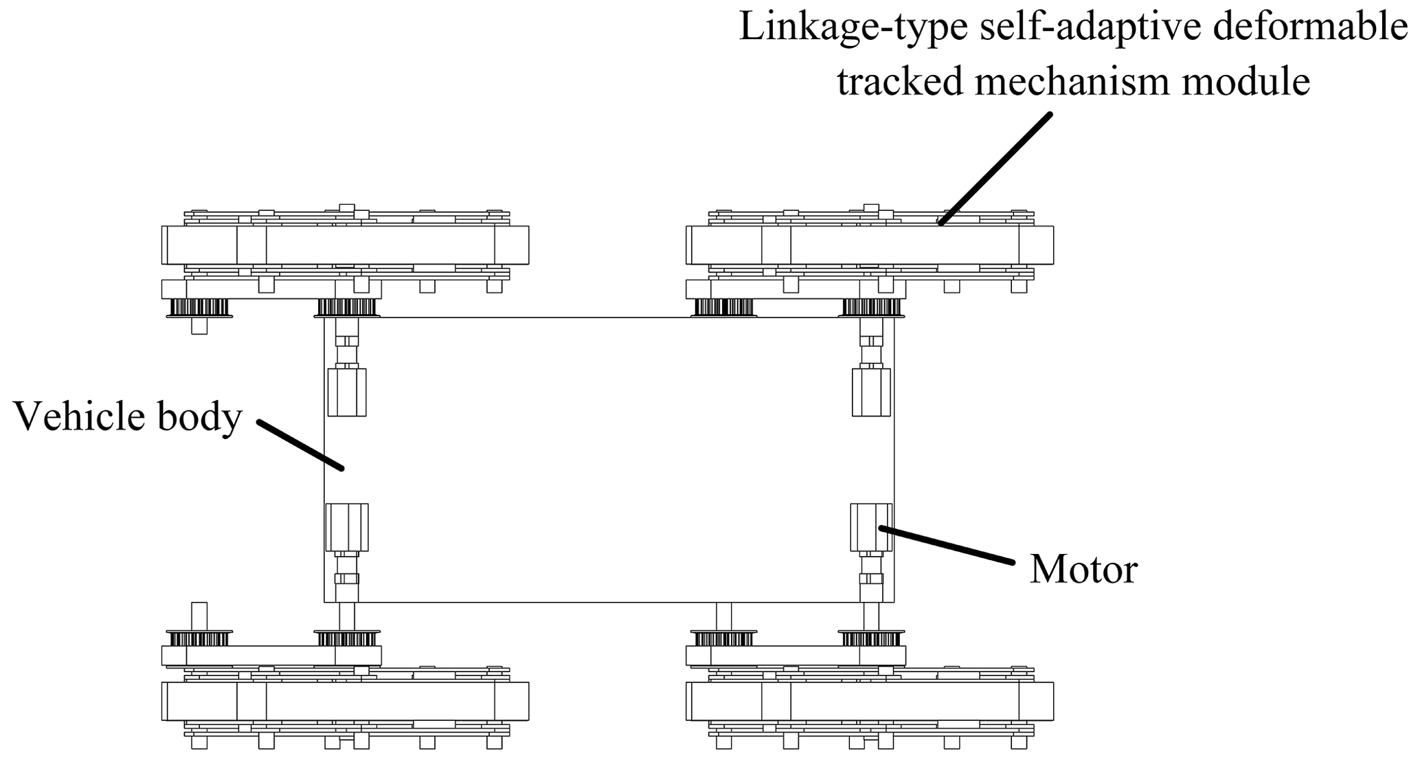
In addition, the deformation of the linkage-type mechanism with multiple DOFs can be challenging to control, so the mechanism with a single DOF is selected for the design. Obviously, at this time, the linkage-type self-adaptive deformable tracked mechanism has a total of 12 DOFs, and the tracked mechanism module connected to the vehicle body has 3 degrees of freedom: the DOF of the deformable tracked mechanism module, the DOF of the tracked mechanism module rotating around the output shaft of the motor, and the DOF of the tracked transmission. The overall mechanism is arranged with four motor drives, which belong to the underactuated device. This paper focuses on the design and analysis of the linkage-type self-adaptive deformable tracked mechanism.
2.2 Design of multi-loop mechanism with a single DOF
According to the design characteristics of the linkage-type self-adaptive deformable tracked mechanism, the external profile of the deformable mechanism can be designed as a six-bar mechanism to form a quadrilateral shape. In order to be designed as a tracked type, its shape is a parallelogram, which can be passively deformed into another parallelogram when encountering obstacles. Figure 2a shows the normal walking state of the track, and Fig. 2b shows the state after deformation, which then shows that the height of the obstacle after deformation is obviously improved. However, the simple planar six-bar mechanism has 3 DOFs, which can be difficult to control. Since the tracked mechanism module needs to connect to the vehicle body, it is necessary to increase the number of connecting links to control the DOFs and connect to the vehicle body. As shown in the redesigned linkage-type mechanism in Fig. 3, a link, BE, which can connect the vehicle body and drive is added, and the link AC is added as an example to limit the DOFs and deformability. In this configuration, the links AB, BC, and AC form a triangle and can be regarded as a component, so the mechanism can still be regarded as a planar six-bar mechanism with 1 DOF and can be connected to the vehicle body. Therefore, the multi-loop mechanism with a single DOF can meet the self-adaptive requirements.

Figure 2Deformation of the planar six-bar mechanism: (a) the normal walking state and (b) the state after deformation.

Considering that it can still walk normally after deformation, the lengths of the links remain constant, and the lengths of the track remains unchanged, the relationship between the links can be obtained, as shown in Eq. (1), which can be used to design the linkage-type self-adaptive deformable tracked mechanism module, where lAB represents the length of the link AB, others are similar, and θ1 represents the angle between link AB and link BC, similarly to what is shown below.
2.3 Design of the linkage-type self-adaptive deformable tracked mechanism module
2.3.1 Design of the tracked mechanism module
Based on the multi-loop mechanism with a single DOF, the pulley and track belt are added, and the revolute joints of the links are connected to the pulleys for the transmission of motion. For enhanced stability, two multi-loop mechanisms with a single DOF are connected to the pulley and track belt in the front and back. The design process of the tracked mechanism module is shown in Fig. 4. Six pulleys are, respectively, located at the revolute joints of the links, and these six pulleys drive the movement of the track mode. Figure 4a is a schematic diagram, and Fig. 4b shows a three-dimensional model of two multi-loop mechanisms with a single DOF, six pulleys, and a one-track belt, in which some positions have some limit designs to avoid singular configurations.

Figure 4Design of the tracked mechanism module: (a) schematic diagram and (b) three-dimensional model.
The designed tracked mechanism module has a single DOF and can be passively deformed when it encounters obstacles. The deformable process is shown in Fig. 5. When the side of link DE encounters obstacles, link CD is passively deformed, and finally link CD is collinear with link DE, and the height of the crossing of the obstacle can be improved by deformation. The linkage-type self-adaptive deformable tracked mechanism module can complete the movement characteristics of the track and can complete the self-adaptive deformation to overcome the obstacle.

2.3.2 Transmission scheme design of the tracked mechanism module
The center of the tracked mechanism module needs to be connected to the motor output shaft, and none of the six pulleys that drive the track are located at the center of the tracked mechanism module. Therefore, it is necessary to design the transmission mechanism to connect the motor output shaft to the track drive pulley. As shown in Fig. 5, the deformable process of the module shows that only the center distance between pulley B or pulley E and the track module remains unchanged during the deformable process, while the center distance between the other four pulleys and the track module continuously changes during the deformable process. Therefore, pulley B or pulley E can be selected to be the driving pulley. Because the transmission process needs to be synchronized, the transmission mode can be selected to be a synchronous belt transmission or gear transmission, as shown in Fig. 6.
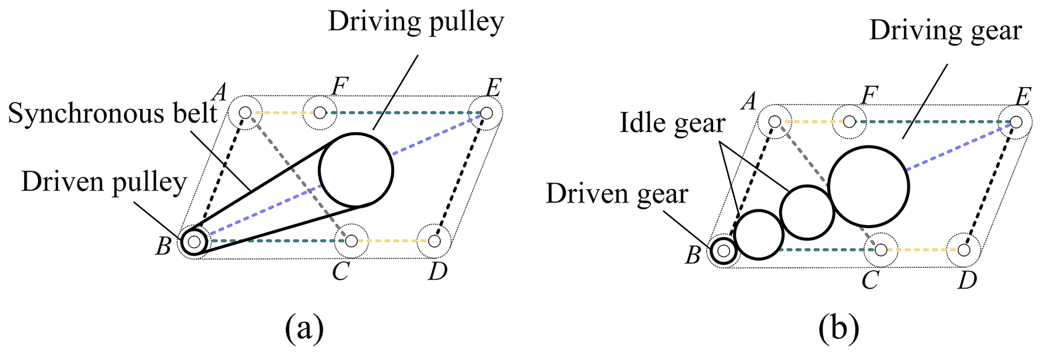
Because of the same type of motor, the rated output torque is inversely proportional to the rated output speed according to the different deceleration ratios. If a larger torque is required, a gearbox with a larger deceleration ratio needs to be selected, which will reduce the maximum output speed. On the other hand, if the speed is high, the torque needs to be sacrificed. This problem leads to a strict demand for the motor. When both speed and torque are required, it is difficult to select a suitable motor. Here, synchronous belt transmission and gear transmission adopt the way of acceleration; that is, the large pulley drives the small pulley or the big gear drives the small gear, which can solve this problem to a certain extent. Figure 6a shows synchronous belt transmission, where the large driving pulley is connected to the vehicle body through a driving shaft. The large driving pulley then drives the smaller driven pulley B via a synchronous belt, thereby propelling the entire tracked module for tracked-type movement. Figure 16b shows gear transmission, where the large driving pulley is also connected to the vehicle body through a driving shaft. In this case, the large driving pulley drives the smaller driven pulley B through a series of gears, thus propelling the entire tracked module for tracked-type movement. Additionally, shaft transmission and chain transmission can also be selected as alternative driving methods, and since each has its own adapted size and scenarios, they can be replaced according to specific circumstances.
2.3.3 Overall design of the tracked mechanism
The transmission scheme of the synchronous belt is selected according to the design scheme of the tracked mechanism module and the transmission scheme. Figure 7 shows the three-dimensional model of the tracked mechanism; the linkage-type self-adaptive deformable tracked mechanism is composed of four motors, four deformable tracked mechanism modules, and a vehicle body. The motion characteristics of a single module determine the motion characteristics of the whole mechanism so the overall obstacle-crossing capabilities and motion performance can be obtained by analyzing a single module.

The tracked mechanism module mainly moves in the form of a track, which can be divided into various types of movement based on the height of the target obstacle, such as tracked-type movement and rocker-arm-type movement. Due to the passive DOF of the deformable tracked mechanism, the tracked mechanism can be self-adaptively deformed to improve the ability to surmount obstacles and move.
3.1 Kinematic analysis
The deformable tracked mechanism can improve the obstacle height through deformation, and the multi-loop six-bar mechanism is passively deformed in the process of deformation. Taking link BC as the benchmark, the coordinate system O (x,y) is established as shown in Fig. 8, point B is regarded as the coordinate origin O, the line where link BC is located is the x axis, the line perpendicular to the x axis and passing through the origin is the y axis, and the angle between link CD and the x axis is denoted by ω. According to the characteristics of the multi-loop six-bar mechanism, 0 ≤ ω ≤ θ1. Based on the lengths of the links, the coordinates and height of each point can be obtained, and the mechanism's obstacle limit can be obtained in the process of movement and deformation. It is obvious that the coordinates of points A, B, C, and D are as shown in Eq. (2):
According to Eq. (2), let the coordinates of point E be (xE, yE), which can be obtained using Eq. (3):
Similarly, the coordinates (xF, yF) of point F can be obtained using Eq. (4):
In summary, the variation relationship of vertex height during the deformable process of a multi-loop six-bar mechanism can be obtained based on specific dimensions.

3.2 Characteristics of tracked movement
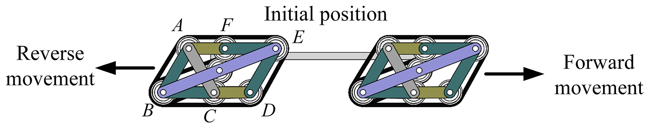
The normal movement form of the linkage-type self-adaptive deformable tracked mechanism on the flat road surface is shown in Fig. 9. Under the action of gravity, according to the characteristics of the mechanism, link BC and link CD are in a collinear position, and the track is in contact with the ground at the same time, and under the action of the parallelogram mechanism, the tracks at link BC and link CD jointly bear the gravity of the mechanism. Therefore, the tracked module is in contact with the ground, which is the same as during the traditional tracked-type movement, and can rely on the tracked-type mobile mechanism with the characteristics of large grounding pressure and strong traction, which can adapt to the soft or rugged ground. It is worth noting that in this article, the movement to the right at the initial position of the mechanism is called forward movement and the movement to the left is called reverse movement.
3.3 The movement of traditional tracked type
Under normal circumstances, the linkage-type self-adaptive deformable tracked mechanism moves and crosses obstacles in the tracked-type form, which is the same as that of traditional tracked-type movement. When the front-end of the track touches an obstacle, the overall center of gravity is raised to cross the obstacle under the action of the tractive force of the track. At this time, the mechanism has an obstacle limit height – that is, the maximum height of the front end of the mechanism. As shown in Fig. 10, the obstacle limit height is denoted by H1, which is determined using Eqs. (2) and (3). It is known that ω=0 and that the diameter of the pulley is denoted as d; then, is obtained.

If the mechanism does not have the ability to deform, the obstacle-crossing process of the tracked mechanism is shown in Fig. 11. Taking the front-tracked module as an example, when encountering obstacles, there is no deformation ability at that moment and DF carries out tracked-type movement along the obstacles (Fig. 11a); when it reaches point D (Fig. 11b), it becomes plane BCD to overcome the obstacles (Fig. 11c) and finally overcomes them (Fig. 11d). The 2 × 2 arrangement makes the front-tracked module provide a certain thrust when it crosses the obstacle, and the front track contacts the steps and the ground at points when encountering the obstacle.

Figure 11Traditional tracked-type obstacle crossing without the deformation capability: (a) initial position, (b) obstacle crossing 1, (c) obstacle crossing 2, and (d) completion of obstacle crossing.

Figure 12Deformable tracked-type obstacle crossing of forward movement: (a) initial position, (b) obstacle crossing 1, (c) obstacle crossing 2, and (d) completion of obstacle crossing.

Figure 13Deformable rocker-arm-type obstacle crossing of forward movement: (a) initial position, (b) obstacle crossing 1, (c) obstacle crossing 2, and (d) completion of obstacle crossing.
3.4 The movement of deformable tracked type
The mechanism has two movement modes: forward movement and reverse movement, and the mechanism has different ways of crossing obstacles according to the height of obstacles. This section will be analyzed from three aspects: forward movement, reverse movement, and climbing movement.
3.4.1 Forward movement
According to the conditions of the limit height of the traditional tracked mechanism and the characteristics of the deformable tracked mechanism, H1 is a critical value for the change in the obstacle-crossing mode of the mechanism. When encountering obstacles with heights lower than H1 and higher than H1, the mechanism can undergo different deformable methods to overcome obstacles.
-
When the height of the obstacle is lower than H1.
As shown in Fig. 12, when the height of the obstacle is lower than H1, taking the front-tracked module as an example, and when encountering obstacles, DE makes contact with the obstacle (Fig. 12a) under the reaction force of the obstacle, and the tracked module is deformed; that is, BC and CD are not in the same straight line (Fig. 12b) until CD and DE are in the same straight line (Fig. 12c). The tracked module continues to overcome the obstacle in the form of tracked-type movement and finally overcomes the obstacles (Fig. 12d). In this process, the deformation of the tracked mechanism in the process of moving over the obstacle occurs; the front track is deformed under the resistance of the steps; and the front-tracked mechanism module is in direct contact with the ground, which has a greater traction force than what is shown in Fig. 11, and the process of overcoming the obstacle will be easier. It can be seen from Fig. 12 that this kind of obstacle-crossing mode is still of the tracked type, but the deformation of the links makes the obstacle-crossing process easier. -
When the height of the obstacle is higher than H1.
As shown in Fig. 13, when the height of the obstacle is higher than H1, taking the front-tracked module as an example, when encountering obstacles, point E makes contact with the obstacle (Fig. 13a) under the reaction force of the obstacle, and the front-tracked module undergoes a wheel-type rotation; that is, plane BCD is not in contact with the ground, but plane DE is in contact with the ground (Fig. 13b), at which time the tracked module continues to rotate in wheel-type movement until plane AFE is in full contact with the obstacle surface (Fig. 13c). The tracked module continues to overcome the obstacle in the form of tracked-type movement and finally overcomes the obstacles (Fig. 13d). In this process, the mechanism will move like a rocker arm. However, there are certain restrictions on the height of the obstacle. As shown in Fig. 13c, the mechanism can cross the obstacle only when the height of the obstacle is lower than .
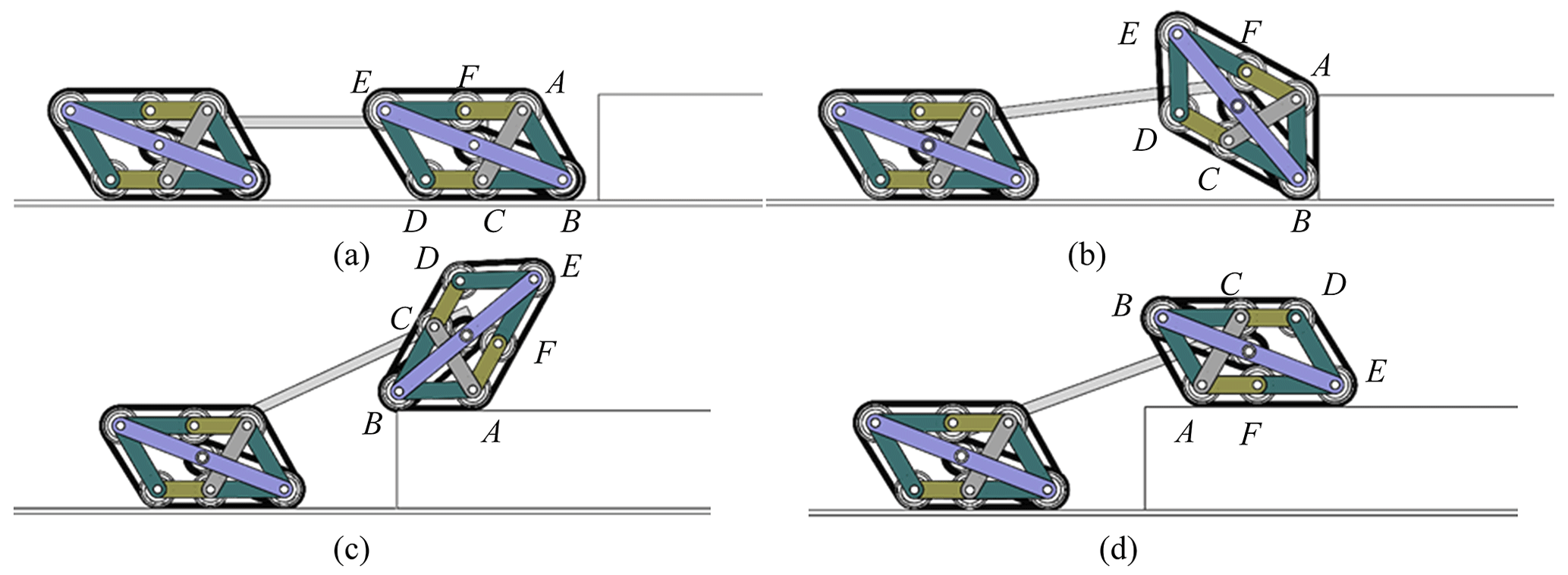
Figure 14Deformable rocker-arm-type obstacle crossing of forward movement: (a) initial position, (b) obstacle crossing 1, (c) obstacle crossing 2, and (d) completion of obstacle crossing.
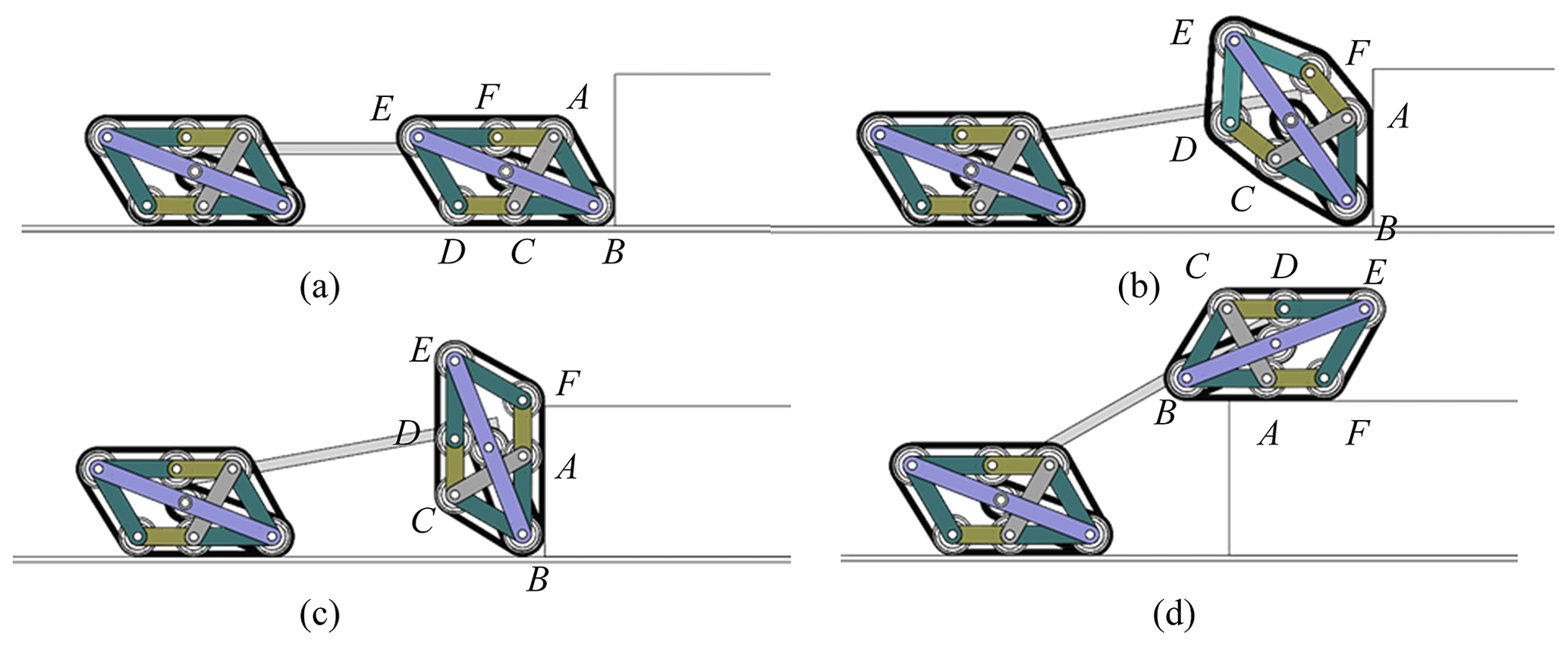
Figure 15Deformable tracked-type obstacle crossing of forward movement: (a) initial position, (b) obstacle crossing 1, (c) obstacle crossing 2, and (d) completion of obstacle crossing.

Figure 16The climbing and downhill process of the deformable tracked mechanism: (a) initial position, (b) climbing 1, (c) climbing 2, and (d) completion of climbing.

Figure 17Prototype model of the linkage-type self-adaptive deformable tracked mechanism module.
3.4.2 Reverse movement
Similarly, from the reverse movement, the way of crossing the obstacle is analyzed when the height of the obstacle is lower than H1 and when the height of the obstacle is higher than H1.
-
When the height of the obstacle is lower than H1.
As shown in Fig. 14, when the height of the obstacle is lower than H1, taking the front-tracked module as an example, when encountering obstacles, point B makes contact with the obstacle (Fig. 14a) under the reaction force of the obstacle, and the front-tracked module undergoes a wheel-type rotation; that is, the plane BCD is not in contact with the ground, at which time the tracked module continues to rotate in a wheel-type motion until plane AB is in full contact with the obstacle surface (Fig. 14b). The tracked module continues to overcome the obstacle (Fig. 14c) and finally overcomes the obstacles (Fig. 14d). In this process, the deformation of the tracked mechanism in the process of moving over the obstacle occurs, and it can be seen that the difference between the reverse movement and the forward movement is that the initial position is different. The second difference is the different way of crossing the obstacle, which can be regarded as a rocker-type obstacle-crossing manner, which is the same as when the forward movement is higher than H1. -
When the height of the obstacle is higher than H1.
As shown in Fig. 15, when the height of the obstacle is higher than H1, taking the front-tracked module as an example, when encountering obstacles, point B makes contact with the obstacle (Fig. 15a) under the reaction force of the obstacle, and the tracked module is deformed and rotate; that is, BC and CD are not in the same straight line (Fig. 15b) until AB and AF are in the same straight line (Fig. 15c). The tracked module continues to overcome the obstacle in the form of tracked-type movement and finally overcomes the obstacles (Fig. 15d). In this process, the mechanism will undergo self-adaptive deformation, and the height of the obstacle is limited to a certain extent, which can only be carried out when the obstacle needs to be lower than H2 as the forward obstacle.
3.4.3 Climbing movement
The climbing and downhill process of the deformable tracked mechanism is shown in Fig. 16; Fig. 16a–d show the climbing process, and Fig. 16d–a show the downhill process, which forms a cycle. When climbing and going downhill, the tracked mechanism module will be deformed by the resistance of the slopes and the ground, respectively. As shown in Fig. 16, taking the front-tracked module as an example, when climbing, point D makes contact with the slope (Fig. 16a) under the reaction force of the obstacle, and the tracked module is deformed; that is, BC and CD are not in the same straight line until CD and DE are in the same straight line (Fig. 16b). The tracked module continues to climb up the slope in the form of tracked-type movement, the front-tracked module completes the climbing (Fig. 16c), and finally the tracked mechanism completes the climbing (Fig. 16d). When moving downhill, still taking the front-tracked module as an example, point C of the front-tracked module makes contact with the ground (Fig. 16c) under the reaction force of the ground, the tracked module is deformed; that is, CD and DE are not in the same straight line until BC and CD are in the same straight line (Fig. 16b). The tracked module continues to descend down the slope in the form of tracked-type movement and finally completes the downhill movement (Fig. 16a). In this process, a part of the tracked mechanism module will always be in contact with the ground or the slope, which ensures enough traction for climbing. Moreover, the mechanism's deformation helps to mitigate the impact on the slope. When the mechanism moves on the slopes, both the hard slopes and the soft slopes can maintain surface contact with the ground to ensure sufficient traction.
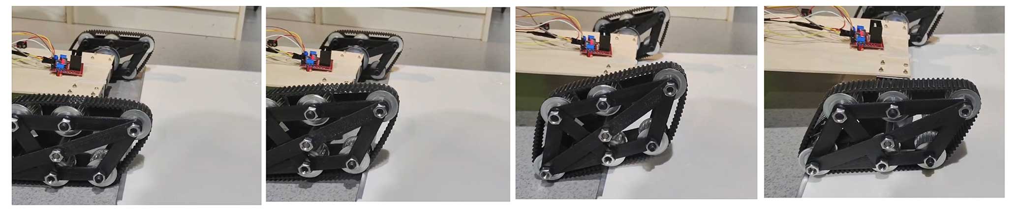
Figure 19Experiment of the traditional tracked-type obstacle crossing without deformation capability.

4.1 Prototype making
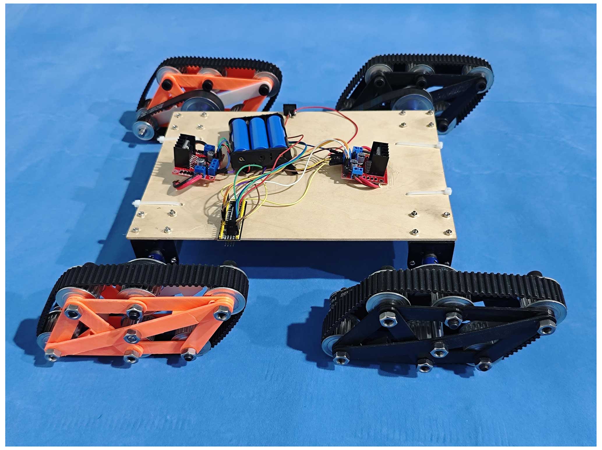
Based on the configuration scheme of the linkage-type self-adaptive deformable tracked mechanism, the non-standard parts are printed using three-dimensional printing technology, some standard parts are purchased, and a principle prototype is designed. In order to facilitate the design, let θ1 = 60° and lAB=lBC, with specific parameters shown in Eq. (5). In addition, the diameter of the pulley is 35 mm, and the number of teeth of transmission pulleys is 30 and 15, respectively. Therefore, the designed linkage-type self-adaptive deformable tracked mechanism module is shown in Fig. 17, which can meet the deformation requirements. According to the design scheme of the tracked mechanism module and the transmission scheme, the prototype model of the tracked mechanism is shown in Fig. 18; the linkage-type self-adaptive deformable tracked mechanism is composed of four motors, four deformable tracked mechanism modules, and a vehicle body.
4.2 Experimental verification
The obstacle-crossing performance of each type of the prototype is verified, respectively. As shown in Fig. 19, the obstacle-crossing experiment of the traditional tracked type without deformation capability was conducted. At this time, the deformed joint was locked. Through the prototype experiment, the mechanism can carry out the traditional racked-type obstacle crossing.
The following experiment of forward movement is conducted to verify the deformable performance of the prototype. As shown in Fig. 20, when the obstacle height is lower than H1, the prototype can cross the obstacle through deformation, which belongs to the tracked type. As shown in Fig. 21, when the obstacle height is higher than H1 and lower than H2, the prototype is able to self-adaptively deform and move in a rocker-arm-type manner.

Figure 21Experiment of the deformable rocker-arm-type obstacle crossing by forward movement.
Similarly, an experiment of reverse movement is conducted to verify the deformable performance of the prototype. As shown in Fig. 22, when the height of the obstacle is lower than H1, the prototype can cross the obstacle by deformation, which belongs to the rocker-arm type. As shown in Fig. 23, when the height of the obstacle is higher than H1 and lower than H2, the prototype can cross the obstacle with self-adaptive deformation. Figure 24 shows the experiment of the climbing and downhill movement process of the deformable tracked mechanism, and the prototype can keep in contact with the slope and can complete climbing and downhill.
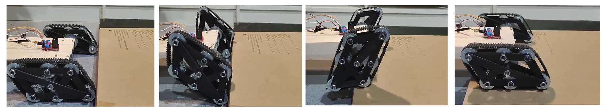
Figure 22Experiment on the deformable rocker-arm-type obstacle crossing by reverse movement.


Figure 24Experiment on the climbing and downhill process of the deformable tracked mechanism.
Through the prototype experiment, it can be seen that the linkage-type self-adaptive deformable tracked mechanism has a variety of obstacle-crossing modes which can complete forward and reverse movement, including the traditional tracked type, deformable tracked type, and rocker-arm type, and that can complete climbing and downhill. The related experimental video can be found in the Supplement. This indicates that such a mechanism possesses excellent terrain adaptability and is capable of overcoming obstacles and traversing soft terrains such as sand, snow, and mud. It can also surmount small obstacles, which suggests it has potential for a wide range of applications.
To design a self-adaptive tracked mechanism that can passively adjust to the height of different obstacles to enhance its obstacle-crossing performance, this paper proposes a linkage-type self-adaptive deformable tracked mechanism based on the design requirements of a self-adaptive deformable mechanism. The design scheme of linkage-type self-adaptive deformable tracked mechanism is put forward, the configuration design method of the tracked mechanism module based on the planar linkage mechanism is obtained, and the transmission scheme is given. The movement characteristics of the module are analyzed, and the kinematics of the module are obtained. The characteristics of the traditional tracked type and deformable tracked type are also given. It is concluded that the mechanism has two modes of movement: forward and reverse, which include the deformable tracked type and rocker-arm type, respectively. Furthermore, it is obtained that this kind of mechanism can complete the climbing and downhill movements. Finally, the three-dimensional printing prototype model is designed for experimental verification, which verifies the feasibility of the mechanism moving over the obstacle. Through the prototype experiment, this kind of mechanism has very good terrain adaptability and can deform through passive self-adaptive obstacles, which has a certain application prospect in some special terrain, such as sand, snow, and mud. Additionally, it can also surmount small obstacles, which suggests it has potential for a wide range of applications.
All the data used in this article can be made available upon reasonable request. Please contact the corresponding author (xmsun@sdmu.edu.cn).
The supplement related to this article is available online at: https://doi.org/10.5194/ms-15-541-2024-supplement.
XS proposed and developed the general concept of the paper. KZ and XS performed the mechanism design and analysis. KZ, RL, ZY, and BY organized the images in the paper. KZ, RL, ZY, and BY were responsible for the paper calibration, and XS guided the writing of the paper.
The contact author has declared that none of the authors has any competing interests.
Publisher's note: Copernicus Publications remains neutral with regard to jurisdictional claims made in the text, published maps, institutional affiliations, or any other geographical representation in this paper. While Copernicus Publications makes every effort to include appropriate place names, the final responsibility lies with the authors.
This work has been supported by the doctoral scientific research foundation of Shandong Management University (grant no. SDMUD202123).
This research has been supported by the doctoral scientific research foundation of Shandong Management University (grant no. SDMUD202123).
This paper was edited by Daniel Condurache and reviewed by three anonymous referees.
Borkar, K. K., Aljrees, T., Pandey S. K., Kumar, A., Singh, M. K., Sinha, A., Singh, K. U., and Sharma V.: Stability Analysis and Navigational Techniques of Wheeled Mobile Robot: A Review, Processes, 11, 3302, https://doi.org/10.3390/pr11123302, 2023.
Bruzzone, L., Nodehi, S. E., and Fanghella, P.: Tracked locomotion systems for ground mobile robots: A review, Machines, 10, 648, https://doi.org/10.3390/machines10080648, 2022.
Cao, Y. X., Liu, B. Y., and Pu, J.: Robust control for a tracked mobile robot based on a finite-time convergence zeroing neural network, Front. Neurorobotics, 17, 1242063, https://doi.org/10.3389/fnbot.2023.1242063, 2023.
Chen, G., Xu, Y. D., Yang, X., Hu, H. S., Cheng, H., Zhu, L. Y., Zhang, J. J., Shi, J. W., and Chai, X. X.: Target tracking control of a bionic mantis shrimp robot with closed-loop central pattern generators, Ocean Eng., 297, 116963, https://doi.org/10.1016/j.oceaneng.2024.116963, 2024.
Chu, A. H., Cheng, T. Y., Muralt, A., and Onal, C. D.: A passively conforming soft robotic gripper with three-dimensional negative bending stiffness fingers, Soft Robot., 10, 556–567, https://doi.org/10.1089/soro.2021.0200, 2023.
Guo, W. Z., Jiang, S. G., Zong, C. G., and Gao, X. S.: Development of a transformable wheel-track mobile robot and obstacle-crossing mode selection, in: 2014 IEEE International Conference on Mechatronics and Automation, Tianjin, China, 3–6 August 2014, IEEE, 1703–1708, https://doi.org/10.1109/ICMA.2014.6885957, 2014.
Hu, Y., Meng, J. Y., Li, G. N., Zhao, D. Z., Feng, G., Zuo, G. K., Liu, Y. F., Zhang, J. J., and Shi, C. C.: Fuzzy Adaptive Passive Control Strategy Design for Upper-Limb End-Effector Rehabilitation Robot, Sensors-Basel, 23, 4042, https://doi.org/10.3390/s23084042, 2023.
Jiang, H., Xu, G. Y., Zeng, W., and Gao, F.: Design and kinematic modeling of a passively-actively transformable mobile robot, Mech. Mach. Theory, 142, 103591, https://doi.org/10.1016/j.mechmachtheory.2019.103591, 2019.
Kislassi, T. and Zarrouk, D.: A Minimally Actuated Reconfigurable Continuous Track Robot, IEEE Robot Autom. Let., 5, 652–659, https://doi.org/10.1109/LRA.2019.2959237, 2020.
Korayem, M. H., Safarbali, M., and Lademakhi, N. Y.: Adaptive robust control with slipping parameters estimation based on intelligent learning for wheeled mobile robot, ISA T., 147, 577–589, https://doi.org/10.1016/j.isatra.2024.02.008, 2024.
Li, J. H., Wang, J. Z., Wang, S. K., Peng, H., Wang, B. M., Qi, W., Zhang, L. B., and Su, H.: Parallel structure of six wheel-legged robot trajectory tracking control with heavy payload under uncertain physical interaction, Assembly Autom., 40, 675–687, https://doi.org/10.1108/AA-08-2019-0148, 2020.
Pan, H. N., Chen, B. L., Huang, K. H., Ren, J. K., Cheng, C., Lu, H. M., and Zhang, H.: Flipper Control Method for Tracked Robot Based on Deep Reinforcement Learning, J. Simul., 36, 405, https://doi.org/10.16182/j.issn1004731x.joss.22-1105, 2024.
Park, S, Shin, J., Kim, Y., and Seo, T.: WAVES: Soft-Material Based Adaptable Walking-Type Stair-Climbing Robot for Various Step Sizes, IEEE Access., 12, 13100–13111, https://doi.org/10.1109/ACCESS.2024.3355955, 2024.
Shu, X., Ni, F. L., Min, K., Liu, Y. C., and Liu, H.: A novel dual-arm adaptive cooperative control framework for carrying variable loads and active anti-overturning, ISA T., S0019–0578, https://doi.org/10.1016/j.isatra.2024.03.011, 2024.
Song, Z., Luo, Z. R., Wei, G. W., and Shang, J. Z.: A portable six-wheeled mobile robot with reconfigurable body and self-adaptable obstacle-climbing mechanisms, J. Mech. Robot., 14, 051010, https://doi.org/10.1115/1.4053529, 2022.
Song, Z., Luo, Z. R., Wei, G. W., and Shang, J. Z.: Self-adaptive obstacle crossing of an AntiBot from reconfiguration control and mechanical adaptation, J. Mech. Robot., 16, 021002, https://doi.org/10.1115/1.4056601, 2024.
Sun, X. M., Li, R. M., Xun, Z. Y., and Yao, Y. A.: A new Bricard-like mechanism with anti-parallelogram units, Mech. Mach. Theory, 147, 103753, https://doi.org/10.1016/j.mechmachtheory.2019.103753, 2020a.
Sun, X. M., Yao, Y. A., and Li, R. M.: Novel method of constructing generalized Hoberman sphere mechanisms based on deployment axes, Front. Mech. Eng.-Prc., 15, 89–99, https://doi.org/10.1007/s11465-019-0567-5, 2020b.
Sun, X. M., Li, R. M., Xun, Z. Y., Kong, X. W., and Yao, Y. A.: A multiple-mode mechanism composed of four antiparallelogram units and four revolute joints, Mech. Mach. Theory, 155, 104106, https://doi.org/10.1016/j.mechmachtheory.2020.104106, 2021.
Sun, X. M., Li, R. M., and Yao, Y. A.: Loop-construction mechanism and its network based on quadrilateral mechanisms, Mech. Mach. Theory, 181, 105181, https://doi.org/10.1016/j.mechmachtheory.2022.105181, 2023.
Sun, Z. B., Heng, T. T., Zhao, L. M., Liu, S. S., Lian, Y. F., and Liu, K. P.: A trajectory tracking method based on robust model predictive control for a bionic ankle–foot aided by a tensegrity mechanism. Eng. Optimiz., 2023, 1–23, https://doi.org/10.1080/0305215X.2023.2280000, 2023.
Wang, D., Fang, B., and Zheng, J.: Design and research of deformable wheel-legged robot based on origami mechanisms, P. I. Mech. Eng. C-J. Mec., 238, 8769–8784, https://doi.org/10.1177/09544062241241417, 2024.
Wei, C. R., Wu, J. X., Sun, J., Sun, H. Z., Yao, Y. A., and Ruan, Q.: Reconfigurable design of a passive locomotion closed-chain multi-legged platform for terrain adaptability, Mech. Mach. Theory, 174, 104936, https://doi.org/10.1016/j.mechmachtheory.2022.104936, 2022.
Willwacher, S., Bruder, A., Robbin, J., Kruppa, J., and Mai, P.: A multidimensional assessment of a novel adaptive versus traditional passive ankle sprain protection systems, Am. J. Sport. Med., 51, 715–722, https://doi.org/10.1177/03635465221146294, 2023.
Wu, J. X., Guo, L., Yan, S. Z., Li, Y. Z., and Yao, Y. A.: Design and performance analysis of a novel closed-chain elastic-bionic leg with one actuated degree of freedom, Mech. Mach. Theory, 165, 104444, https://doi.org/10.1016/j.mechmachtheory.2021.104444, 2021.
Xu, R. and Liu, C.: Tracked robot with underactuated tension-driven RRP transformable mechanism: ideas and design, Front. Mech. Eng.-Prc., 19, 4, https://doi.org/10.1007/s11465-023-0777-8, 2024.
Ye, C. L., Du, Y. F., Yu, S. Y., Zhao, Q., and Jiang, C. Y.: Design and performance analysis of an adaptive omnidirectional wheel for heavy payload robot, Ind. Robot, 49, 1144–1155, https://doi.org/10.1108/IR-01-2022-0024, 2022.
Yi, C. K., Chen, X. C., Zhang, Y., Qi, H. X., Liu, Y. L., and Huang, Q.: Simulating the GRF of Humanoid Robot Vertical Jumping Using a Simplified Model with a Foot Structure for Foot Design, J. Bionic Eng., 21, 112–125, https://doi.org/10.1007/s42235-023-00429-8, 2024.
Zhang, F., Yu, Y., Wang, Q., Zeng, X. Y., and Niu, H. Q.: A terrain-adaptive robot prototype designed for bumpy-surface exploration, Mech. Mach. Theory, 141, 213–225, https://doi.org/10.1016/j.mechmachtheory.2019.07.008, 2019.
Zhang, F., Yu, Y., Wang, Q., and Zeng, X. Y.: Physics-driven locomotion planning method for a planar closed-loop terrain-adaptive robot, Mech. Mach. Theory, 162, 104353, https://doi.org/10.1016/j.mechmachtheory.2021.104353, 2021.
- Abstract
- Introduction
- Configuration design of the linkage-type self-adaptive deformable tracked mechanism
- Analysis of movement characteristics of deformable tracked mechanism module
- Prototype making and experimental verification
- Conclusion
- Data availability
- Author contributions
- Competing interests
- Disclaimer
- Acknowledgements
- Financial support
- Review statement
- References
- Supplement