the Creative Commons Attribution 4.0 License.
the Creative Commons Attribution 4.0 License.
 | 30 Aug 2024
Stability analysis and control method of a variable structure detection robot for underground rescue
Hai-bo Tian
Ao Wang
Maolin Lu
Meiting Zhang
Zenan Zhang
Wencai Zhang
Xin Su
To meet the needs of drilling rescue, a variable structure detection robot for underground rescue was designed for the motion requirements of a small crawler robot in underground unstructured environments. The robot can improve the stability and anti-overturning ability of the system through its own configuration changes. The existing stability criteria are computationally complex and cannot meet the requirements of real-time control. Therefore, a stability criterion based on the contact force between the robot and the ground is proposed, and a robot adaptive stability control system was established based on back propagation (BP) neural network. The system can change the robot configuration in real time to ensure the overturning stability. The criterion is analyzed and compared with the existing stability methods, and the influence of the control system on the dynamic stability of the robot in three typical terrains is discussed. The robot simulation test model is established to simulate the robot's driving process on unstructured road and the process of adjusting the arm configuration on the slope. Finally, the stability control processes of the robot on a longitudinal slope and a transverse slope are experimentally analyzed. The analysis results show that the stability criterion is accurate and efficient, and the adaptive control system can improve the stability of the robot.
- Article
(7807 KB) - Full-text XML
- BibTeX
- EndNote


There are various high-risk factors in the underground environment after an accident. It is difficult for rescuers to enter the accident site in the first place, but it is urgent to obtain the underground situation to make the right decisions. It is undoubtedly an effective and safe solution to first enter the underground environment with a rescue detection robot, detect on-site information, transport rescue materials, and establish communication channels with the affected personnel (Maimone, 2019). Therefore, research of detection robots for underground rescue is of great significance for reducing casualties and improving emergency rescue capabilities. However, mines present a wide variety of challenges to virtually all aspects of robots, including challenging and complex terrain, communication denial, and sensory degradation. In addition, procedures for robot deployment and operator control must be highly automated, robust, and reliable (Miller et al., 2020). At present, most of the detection robots for underground rescue at home and abroad are tracked because of the advantages of tracked robots, such as good obstacle surmounting performance (Dai and Jia, 2010). The crawler-type rescue robot Hibiscus developed by Japan can explore dangerous areas in disaster areas and map them for rescuers (Yan, 2020). The coal mine rescue robot CUMT-I developed by the China University of Mining and Technology is equipped with low-light cameras, gas sensors, thermometers, and other equipment, with two-way voice intercom function and a wireless network communication function (Yan, 2020). The six-crawler and four-swing-arm coal mine rescue detection robot developed by Xi'an University of Science and Technology has achieved a series of research results in robot autonomous navigation and intelligent control (Guo, 2023). Although the above robots have complete functions, they are too large to meet the needs of drilling rescue. They can only go down from normal roadways. In the Utah mine disaster, rescuers used a modified Inuktun tracked robot to enter the underground roadway through a channel formed by ground drilling to carry out detection and rescue work. However, due to the complex underground terrain structure, the robot's obstacle crossing and anti-overturning ability are insufficient, and the test failed (Zhu et al., 2019). Therefore, considering the task requirements and the actual mine hole environment, the robot should have a specific adaptability to changes in the hole diameter and an excellent crawling ability at the same time (Ge et al., 2023), so the design of a variable structure robot is a better choice to meet the needs.
Motion stability is key for the rescue detection robot to adapt to the complex underground environment. The combination of a reasonable stability judgment standard and an efficient control system can monitor the stability of the robot in real time under dynamic conditions and provide a guarantee for the robot to make correct decisions. Existing stability criteria are mainly based on the distance between the robot support polygon and the center of gravity projection or the distance between the support polygon and the net force vector acting on the center of gravity. These are the conjugate gradient (CG) projection method (Taheri and Mozayani, 2023), static stability margin (SSM) (Toupet et al., 2020), center of pressure method (COP) (Reher and Ames, 2021), effective mass center (EMC) (Elhosseini et al., 2019), zero moment point (ZMP) (An et al., 2021), tumble stability margin (TSM) (Uno et al., 2019), and force-angle stability measure (FASM) (Zhao et al., 2023). Compared with the distance-based stability criterion, the energy-based criterion focuses on the energy difference of the robot in different situations and has better accuracy, including the energy stability margin (ESM) (Ryu et al., 2023), the dynamic energy stability margin (DESM) (Bachega et al., 2023), normalized dynamic energy stability margin (NDESM) (Polo and Alcantara, 2020), etc. This kind of method still has shortcomings, such as complex calculation, and the change of robot structure has a great influence on the calculation results, which cannot meet the requirements of real-time stability control (Liu and Liu, 2010). The force-based standard focuses on the body contact force of the robot, including the foot force stability margin (FFSM) and the modified foot force stability margin (MFFSM) (Agheli and Nestinger, 2016). Although the two methods are simple in calculation, they are only suitable for legged robots with central symmetrical structures.
In this paper, we present a variable structure detection robot for underground rescue that was designed for the rescue environment of a 225 mm diameter borehole, combined with the leading arm and the deformable track. Aiming at the driving requirements of the robot on complex roads, a stability criterion based on the contact force between the robot and the road surface (contact force stability criterion, CFSC) is proposed, and an adaptive stability control system of the robot is established in combination with a back propagation (BP) neural network. According to the overturning stability index value, the system can ensure the overturning stability of the robot by controlling the configuration change of the leading arm. The simulation test model is established, the physical experiment is carried out, and the theoretical analysis results are verified.
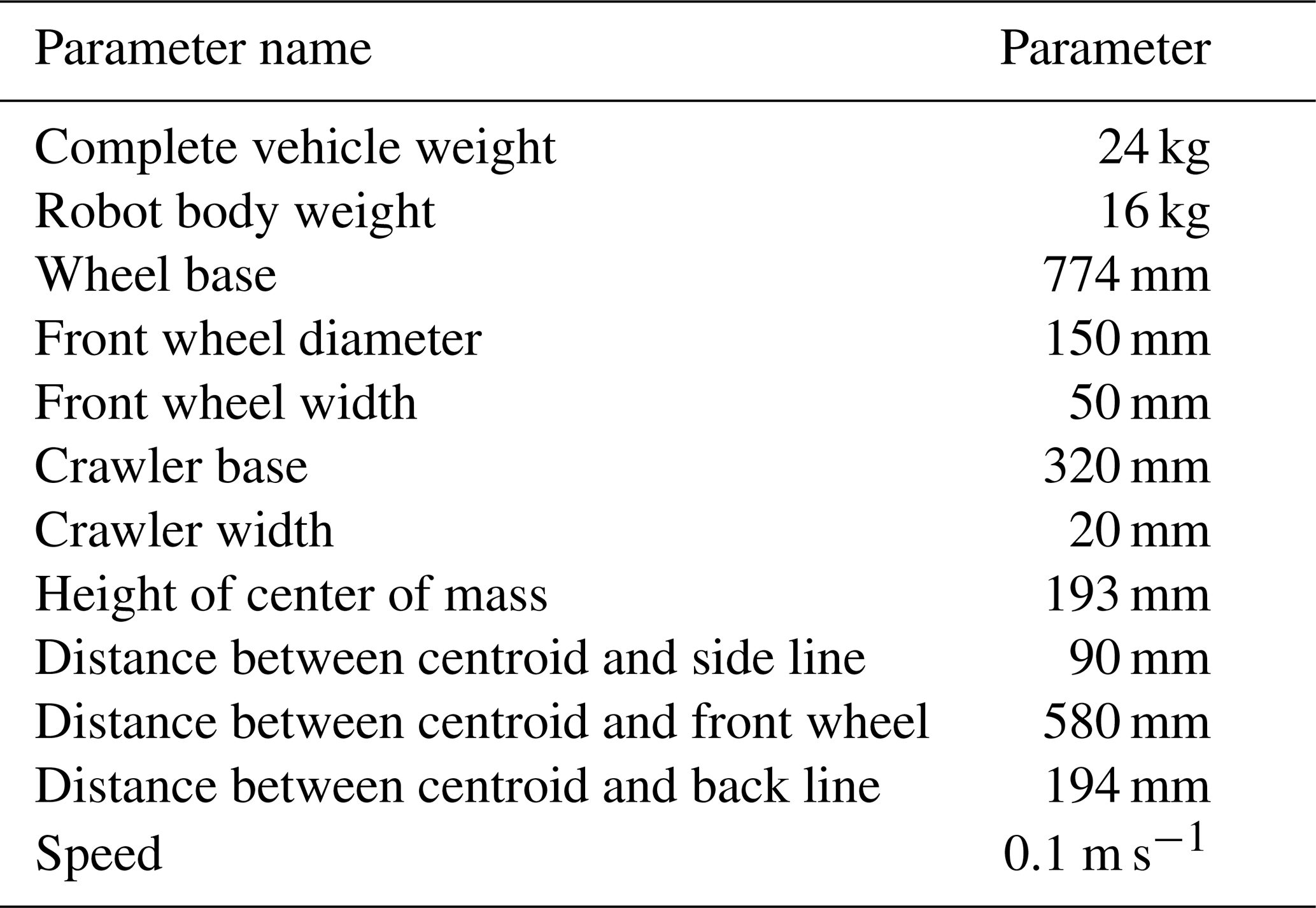
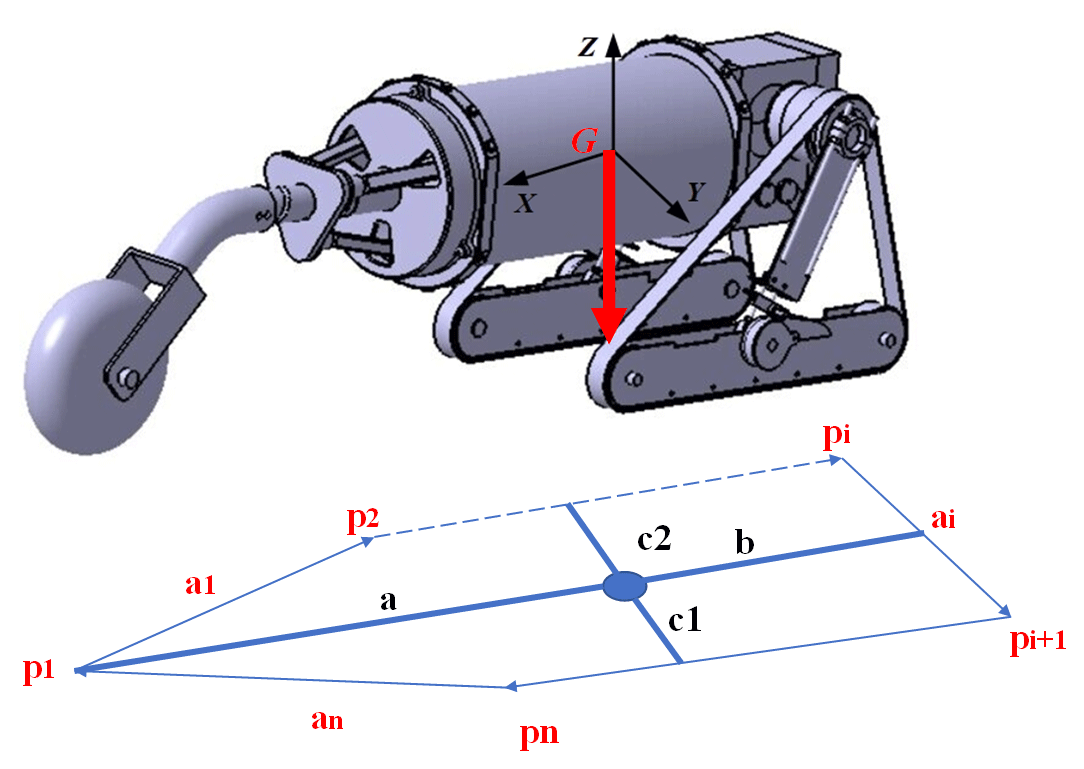
To enable the robot to pass through small-diameter boreholes and still have good trafficability and anti-overturning ability underground, a variable structure robot is presented in this paper, which is composed of leading arm, robot body (including motors, sensors, control systems), and crawler driving unit. The topology graph of the robot is shown in Fig. 1, the main structural parameters are shown in Table 1, and the CAD model of the robot is shown in Fig. 2.


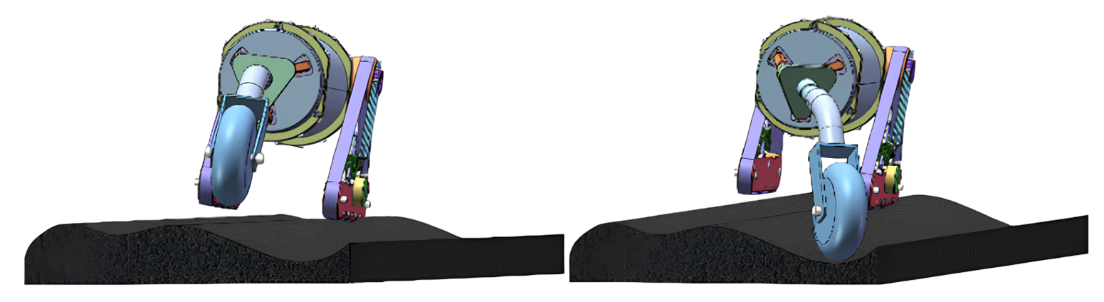
The design of the leading mechanical arm is based on the parallel mechanism. Based on the traditional 3-RPS (revolute–prismatic–spherical) parallel mechanism, the cable-screw branch chain is added to realize the rotation of the front wheel around the center line of the vehicle body to adjust the stability of the robot by changing the configuration of the arm. Figure 3 shows the process of adjusting the configuration of the arm to prevent rollover.
The robot body is made of thick steel pipe, with high strength and stiffness. It is equipped with bull's eye wheels, which can move on the ground under the impetus of the driving device. A variety of sensors can be installed in the body to detect the underground environment, and an underground map can be established to lay the foundation for subsequent rescue work.
The deformable crawler of the robot includes crawler, driving wheel, supporting wheel, and crawler swing arm. It can shrink when entering a small-diameter hole, and automatically expand after reaching the underground, and always maintain the configuration when moving underground.
3.1 Working environment
The working environment of the robot mainly refers to the terrain environment of the road surface (Tian and Fang, 2009). The mine disaster environment makes the underground road surface environment more complex: one is the three-dimensional complexity of the road surface, that is, the geometric shape of the road surface, including the ups and downs of the ramp, the trenches, and the bumps and depressions of the road surface; the second is the complexity of the physical state of the road surface, including the soil properties of the road surface, the sinking characteristics, the friction characteristics, etc. Different terrain features have different effects on the motion performance of the robot, which is a great challenge for the driving stability of the robot (Lin et al., 2023). Therefore, it is necessary to have a comprehensive analysis and estimation of the terrain environment in advance.
3.2 Self-stability analysis and control
When the robot is working underground, the rugged and complex road conditions require the robot arm to actively adjust the configuration and maintain driving stability. Therefore, the structure and center of gravity of the robot will often change. Because the ground interference factors can be directly reflected in the contact force between the robot and the ground, measured by the force sensors, this paper proposes a stability criterion based on the contact force. In addition to the appropriate stability criterion, there must be a control system with strong function and high efficiency; the control system plays a pivotal role in motion control tasks, enabling the robot to promptly react to feedback from environmental information and thereby achieve autonomous control (Chen et al., 2024a). In an environment that cannot be fully predicted, the two combine with each other to deal with the current capsizing event in a way that quickly responds to the integrated task.
4.1 Stability criterion based on contact force between robot and ground
To analyze the stability of a robot, the friction coefficient is normally assumed to be sufficient to prevent the robot from slipping (Song et al., 2023). All contacts between the robot and contact surfaces are assumed to be point contacts and line contacts. Hence, all contacts do not lie on a single edge of the support polygon. According to the dynamic energy stability model, if the torque generated by the contact between the robot and the ground on any side of the support polygon is positive, that is, Mj>0 , then the robot has dynamic stability. From Newton's law, the following equation must be satisfied about every jth edge of the support polygon:
where Min,j is the moment due to the inertial force, moment Mg,j is the moment due to the gravitational force, moment Mm,j is the moment due to the manipulation (external) forces and moments, and Ms,j is the moment due to the foot contact forces and moments. All of the moments are calculated about the jth edge of the support polygon. From Eq. (1), the following can be written:
The right-hand side terms of Eq. (2) sum up to the net moment, acting about the jth edge of the support polygon, caused by the net force and moments acting on the system. Replacing the right-hand side of Eq. (2) with MN,j gives the following:
Hence, for a robot to be considered to have a dynamically stable stance, the net moment about the jth edge of the support polygon caused by all the foot forces must be negative, and its magnitude must be the same as the Ms,j. Otherwise, the robot will rotate about that edge and tumble. For the detection robot for underground rescue studied in this paper, the net torque on the bottom support edge line is generated by the contact force of other touch points, so the stability of the robot can be expressed in the following ways.
The corners of the convex polygon on the bottom of the robot are marked sequentially in the clockwise direction in the case of overlooking, as shown in Fig. 4, which are recorded as , forming the bottom edge of the polygon on the bottom of the robot, that is, the supporting edge line, recorded as
At time t, the robot's bottom polygon will be affected by the ground contact force. At this time, the overturning stability margin of the robot's side line ai can be expressed by the sum of the contact torques on the side line:
where is the sum of the moments of the normal contact force on the side line ai at all contact points, and u represents the ground friction coefficient.
When the contact is a line contact, the moment of the contact force on the contact line to the side line ai can be regarded as the sum of the product of the contact force of multiple points and the position vector perpendicular to the side line ai. Considering the global stability of the robot, take
The overturning stability index based on the contact force stability criterion (the following referred to as the overturning stability index) is obtained by normalizing the weight of the robot:
When ECFSC>0, the robot meets the dynamic stability conditions in the standardized dynamic energy stability model and has dynamic stability; when ECFSC=0, the robot is in a critical overturning state; and when ECFSC<0, the robot is in a state of instability.
In the actual underground operation process, the robot also needs to consider the influence of external effects, such as impact, obstacle interference, and so on. The generated force and torque can be expressed as the center of gravity of the robot. It is assumed that the size of the external force can be seen as fo, the size of the external torque can be seen as mo, and the equivalent force along the overturning line can be expressed as
where li is a straight line perpendicular to the center of gravity and the toppling line ai, which can be expressed by the following equation:
These effects can be reflected in the contact force between the robot and the ground. From this point of view, CFSC is a dynamic stability criterion, which is suitable for all the working conditions of the robot studied in this paper.
4.2 Stability control based on criterion
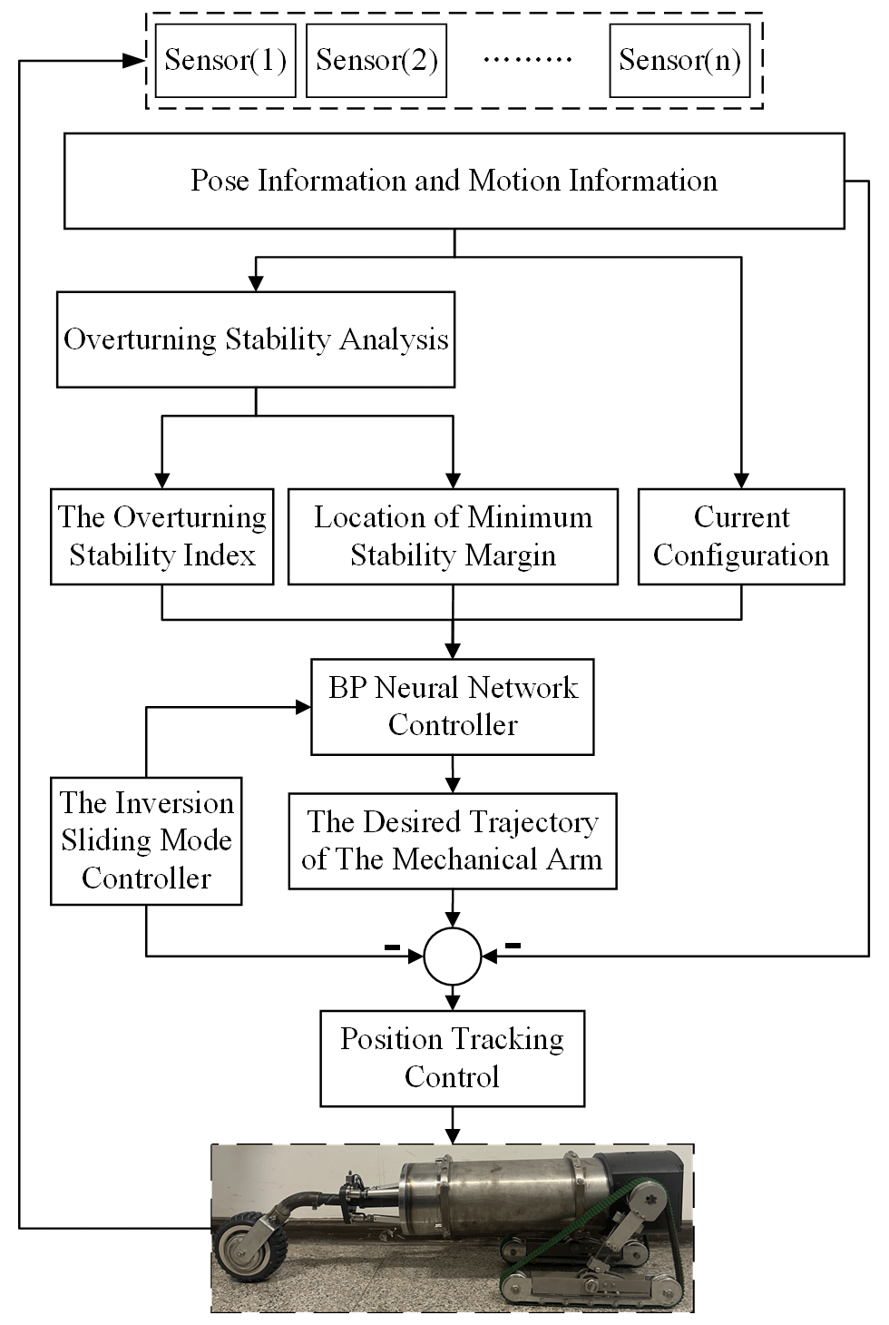
The real-time stability control strategy can continuously monitor the stability of the system according to the stability criterion and respond if necessary to enhance the stability of the system. Since the force sensor data can be measured intuitively, the overturning stability index can be directly integrated into the current control strategy as a stability measure, combined with the BP neural network to control the change of the robot's leading arm configuration, as shown in Fig. 5.
The system uses a BP neural network to coordinate and control the motor of the robot's leading arm and change its configuration and motion parameters, thereby changing the overturning stability index and ensuring that the overturning stability index is within the controllable range. The attitude information and motion parameters of the robot can be measured by the sensors. After organization and coordination, the necessary A/D (analog–digital) conversion is carried out and transmitted to the BP neural network controller. By coordinating the information provided by the sensing system and the calculated motion stability information, the controller obtains the expected trajectory of the robot's leading arm and drives the motor to work. At the same time, the system has a real-time feedback adjustment function. The backstepping sliding mode controller realizes the tracking control of the output angular position of the arm and ensures the robustness of the system.
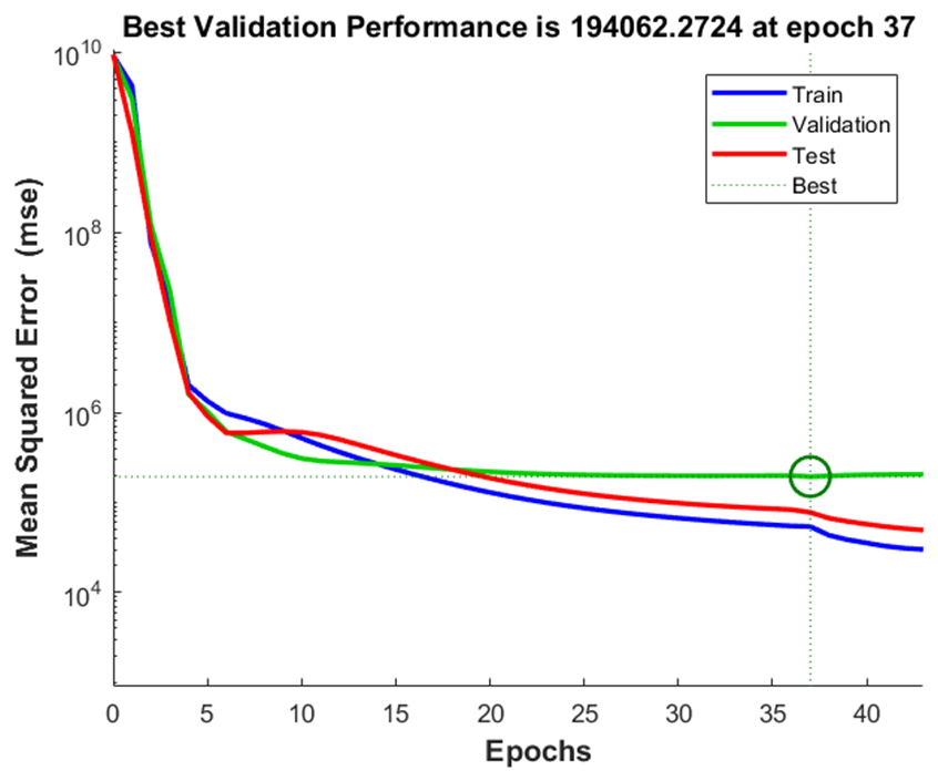
According to the data information measured by the sensors, the overturning stability index of the robot can be obtained, and then a BP neural network controller is used to obtain the angular displacement of the robot's leading arm. The input variable is the overturning stability index; the ratio of training samples, verification samples, and test samples is ; the number of neurons in the hidden layer is 10; the training algorithm is the inversion propagation algorithm (Ranjan et al., 2018); and the output is the swing angle of the swing arm. The sample data are a total of 658 groups. The training performance diagram is shown in Fig. 6, and the regression fitting diagram is shown in Fig. 7.

From Fig. 6, when the neural network training is iterated 37 times, the fitting relationship between input and output reaches the optimal solution. It can be seen from Fig. 7 that the R values of all data samples are higher than 0.99, indicating that the fitting relationship between input and output has reached a better level in theory, and stability control can be carried out.
5.1 Modelling contact forces
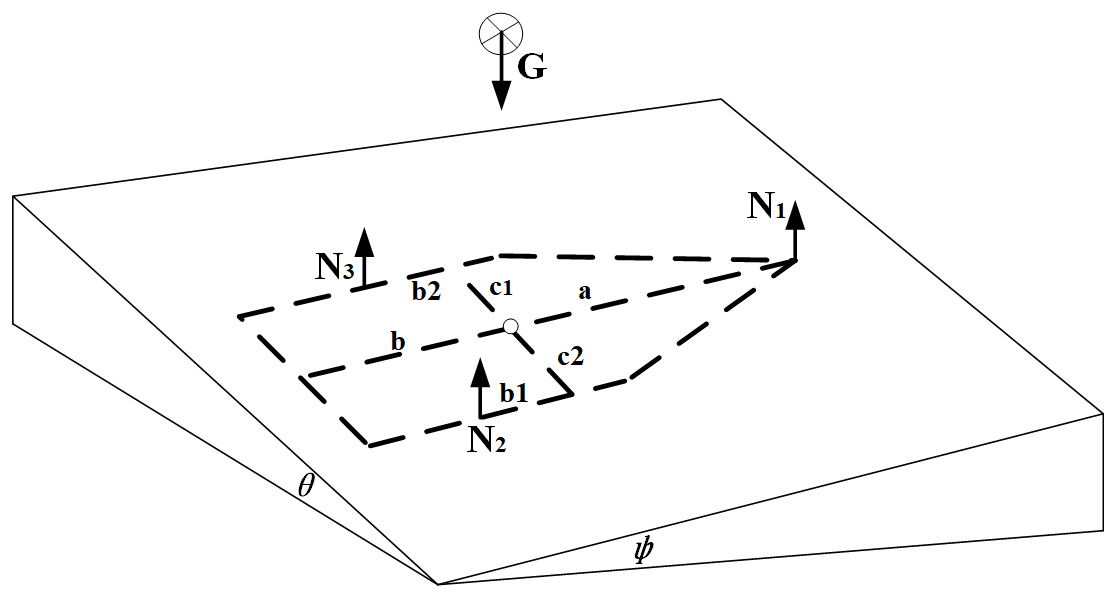
To analyze and calculate the overturning stability index of the robot, it is necessary to study the contact force of the robot when driving on the unstructured road surface. Although the underground environment is complex, based on the size of the robot, it can be divided into two categories: obstacles that the robot can pass through and obstacles that the robot cannot pass through. When the robot encounters obstacles that can be passed, the body may tilt at a small angle. During these instances, the forces acting on the robot resemble those experienced on a gentle slope, allowing for substitution with such a slope for analysis. When encountering obstacles that it cannot pass, the robot will choose to detour. This article will not study such obstacles. Therefore, the following slope with both longitudinal and transverse components is used to simulate most of the terrain conditions that the robot can pass through underground (Mascarich et al., 2020). Because the track width is smaller than the wheelbase, its influence on the calculation is ignored in the study (Erden and Leblebiciolu, 2007). The normal force of each contact point of the mobile robot is shown in Fig. 8.
Force balance:
Moment equilibrium:
From Eqs. (11) to (13), we can find
where a is the distance between the center of gravity and the front axle, b is the distance between the center of gravity and the rear axle, c is the length between the two tracks, c1 is the distance between the center of gravity and the side line of the robot, c2 is the distance between the center of gravity and the right-side line of the robot, and h is the height of the center of mass.
Therefore, if the longitudinal slope, roll angle, and center of gravity of the terrain are known, the normal contact force can be obtained. At the same time, when the configuration of the robot arm changes, the normal contact force can be determined by changing the values of a, b, and c. The overturning stability index of the robot in this state can be obtained by substituting the obtained contact force into Eq. (14).
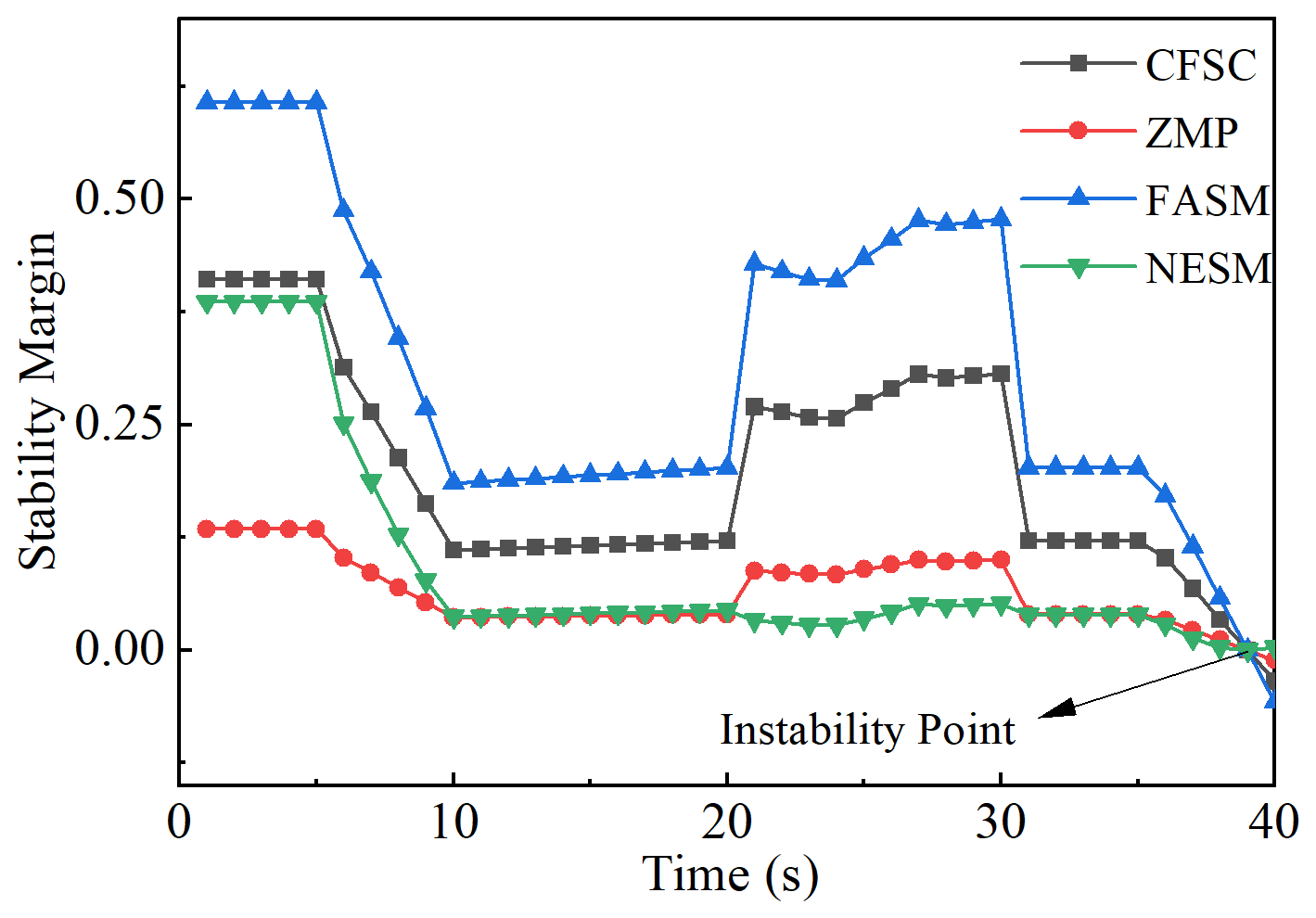
Table 2Comparison of calculation time of 4 methods. NESM represents the normalized energy stability margin.

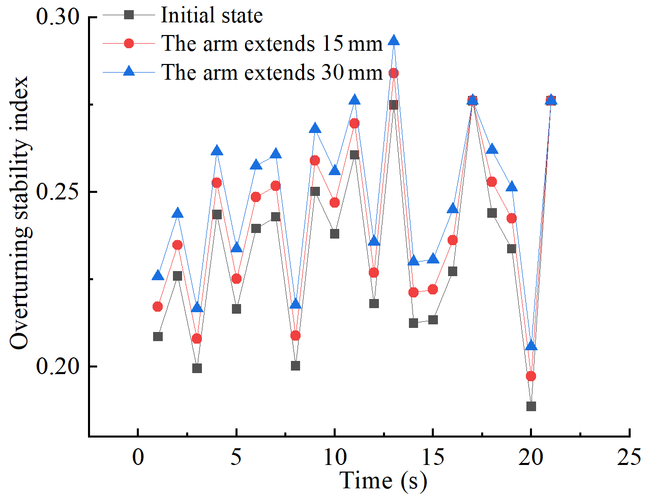

Figure 11(a) Stability control under inclined terrain; (b) stability control in pitched–tilted terrain.
5.2 Simulated roadway
During the underground operation of the rescue detection robot, due to the influence of terrain, ground force imbalance, and other factors, the robot system will present front and back pitching, left and right tilting, and their combination states (Roan et al., 2010). The robot's stability is directly reflected in its attitude changes during movement, particularly in terms of roll and pitch angles (Chen et al., 2024b). The centroid of the robot system is taken as the origin of the coordinate, and the rectangular coordinate system o-xyz is established. The positive direction of the robot's forward direction is taken as the x axis, the direction perpendicular to the forward direction to the right is taken as the y axis, and the direction perpendicular to the robot's body plane is taken as the z axis. For the robot, the technical parameters of the whole vehicle can be approximately regarded as unchanged when the terrain changes. The changes are the longitudinal inclination angle, lateral inclination angle, center of gravity position, and the direction and size of the normal contact force with the ground. The change of terrain is equivalent to the forward and backward pitch, left and right tilt, and their combination of the robot system (Wong et al., 2019). Assuming forward and backward pitch, the slope of left and right tilt is less than 30°, the random terrain changes around the xaxis and the y axis are defined as
where δu(t) and δv(t) are random numbers that change with time t between 0 and 1, and the sizes are not necessarily the same. At time t, the mobile robot system first tilts around the x axis angle φ and then tilts around the y axis angle θ, which is brought into Eq. (14). The normal contact force between the robot and the ground can be obtained. The obtained force is brought into Eq. (6), and the overturning stability index at time t can be obtained.
5.3 Analysis and comparison of CFSC and other methods
To verify the reliability and efficiency of CFSC, it is compared with the ZMP, FASM, and NESM methods, which are commonly used stability analysis methods for mobile robots. The mass of the detection robot for underground rescue is 24 kg, the friction coefficient between the track and the ground is u1=2.9, and the friction coefficient between the front guide wheel and the ground is u2=0.8 (Haikal, 2023).
Using t to represent the time of each stage of the robot, the robot in the simulation scene has gone through four stages: when s, the longitudinal slope of the ground gradually changed from 0 to 25°; when s, the leading mechanical arm is gradually elongated by 30 mm from the initial state; when s, the arm is gradually deflected to the left by 26 degrees; when s, the lateral tilt angle of the terrain to the left gradually changed from 0 to 25°. The curve of the stability margin of the four methods with time is shown in Fig. 9. At t, the calculation time of the four methods is shown in Table 2.

Figure 12(a) The influence of inertia force and arm elongation on dynamic stability (the positive inertial force represents that the direction of the inertial force is the same as that of the robot, and the negative inertial force represents that the direction of the inertial force is opposite to that of the robot); (b) the influence of the deflection angle and lateral slope of the arm on the dynamic stability.

Comparing the stability margin trends of the four stages of the four methods, the following results can be obtained. In the first stage, as the longitudinal slope of the ground increases, the stability margin of the robot decreases and the stability becomes worse. In the second stage, after the robot arm is elongated, the stability margin increases slightly and the stability is improved. In the third stage, when the deflection angle of the arm is changed, the stability margin of the robot is obviously improved, which indicates that the deflection of the arm improves the stability of the robot. In the fourth stage, the stability margin decreases, indicating that the change of slope angle reduces the stability of the robot. And CFSC and the other three methods have the same instability point and change trend, which verifies the accuracy of CFSC. By comparing the calculation time of the four methods at time t with MATLAB, it is found that CFSC is shortened by half, which shows that the method is simple and efficient.
5.4 The improvement of dynamic stability by the adaptive control system
When the robot is driving on the simulated road surface, it will be affected by the inertia force and the control force. The two forces have different effects on the overturning stability of the robot: the robot's overturning due to the inertia force often occurs in the start-up and braking stages on the large slope pitch slope; the control force is mainly generated by the change of the arm configuration, which affects the stability of the body when the arm is deflected.
The mass of the robot is 24 kg, and the acceleration is 0.32 m s−2 when the driving motor outputs at full power. The inertia force of the robot at this time is 7.68 N calculated by Newton's second law of motion. Due to the slow speed of the robot, it can maintain a consistent speed even when the passable terrain changes, and the resulting inertial force is smaller than that when the motor is started. To prove the effectiveness of stability control under extreme conditions, the inertial force is set to 10 N. On the pitch terrain, it is assumed that 10 N inertial force is applied when the robot goes uphill (taking the forward direction of the robot as positive), and −10 N inertial force is applied when it goes downhill to represent the robot's acceleration uphill and braking downhill processes. The elongation range of the arm is controlled to be 0–30 mm. After calculation, the maximum pitch angle of the robot is 27° when the driving motor is at full power. Therefore, the range of road slope is 0–25°, the sampling time is 21 s, and the number of sampling data points is 21. The overturning stability index of the robot under the pitch road can be calculated by Eqs. (6)–(15), as shown in Fig. 10.
At the same time, the overturning stability index of the robot with the mechanical arm elongation of 30 mm, the mechanical arm elongation of 15 mm, and the initial state decreases in turn, indicating that on the pitch road surface, when the inertial force is 10 N, the dynamic stability of the robot gradually increases with the increase in the length of the mechanical arm.
Figure 11 simulates the stability control process of the robot while driving on different terrains and considers the influence of the control force. When the overturning stability index is less than 0.05, the deflection of the arm is controlled to prevent roll, and the change trend of the overturning stability index with time is obtained.

It can be seen from Fig. 11 that the stability control of the arm can improve the overturning stability index of the robot on the inclined terrain and improve the stability of the robot to prevent overturning, and different deflection angles of the arm have different effects on the stability under different lateral slopes. On the simulated pitch–tilt combined road surface, an inertial force of 10 N is applied, and the arm control system is added. The change of overturning stability index with time is shown in Fig. 11b.
It can be seen from Fig. 11b that on the pitch–tilt combined road surface, the arm control system can improve the overturning stability index of the robot, that is, improve the dynamic stability of the robot and the anti-overturning ability at critical overturning.
Because the size of the inertial force is also affected by the road conditions when the robot is working, the size of the inertial force is random. To study the influence of different inertial forces on the stability of the robot with different arm elongations, the 25° longitudinal slope is taken. The surface of the overturning stability index with the inertial force and the arm elongation is obtained, as shown in Fig. 12a.

Figure 16The change of normal contact force and the overturning stability index during critical overturning.

It can be seen from Fig. 12a that for the 25° positive slope, with the increase in the elongation of the arm, the overturning stability index increases linearly, indicating that the dynamic stability is improved. For the same arm configuration, when the direction of inertia force is consistent with the forward direction of the robot, with the increase in inertia force, the overturning stability index increases linearly and the dynamic stability increases. When the direction of the inertial force is opposite to the direction of the robot, with the increase in the inertial force, the overturning stability index decreases linearly and the dynamic stability decreases.
From the analysis results of Fig. 11a, the influence of the deflection angle of the arm on the stability under different lateral slopes changes always. Therefore, it is necessary to analyze the influence of different deflection angles on the stability of the robot under different lateral slopes, and obtain the overturning stability index with the lateral slope β and the deflection angle of the arm α, as shown in Fig. 12b.
It can be seen from Fig. 12b that for the transverse slope, as the slope becomes steeper, the overturning stability index of the robot decreases linearly, indicating that its dynamic stability gradually decreases. On the same slope, considering the control force, when the deflection angle of the arm in the inclined direction is less than 5° or greater than 15°, the overturning stability index of the robot is improved, and the dynamic stability of the robot is improved. When the deflection angle of the arm is 5–10°, the overturning stability index of the robot does not change significantly.
To verify the effectiveness of the stability criterion and the adaptive stability control system in the real road environment, the Adams software is used to simulate the robot's driving process on the unstructured road and the process of adjusting the arm configuration on the slope, and the simulation results are compared with the theoretical analysis results.

Figure 18The change of normal contact force and the overturning stability index when the arm is deflected.

6.1 Simulation experiments and analysis in unstructured environments
According to the specific design size of the underground rescue detection robot, the robot model and the simulated road surface are established in the simulation software Adams. The motion pair and drive are added to the robot, and the contact between the robot and the simulated road surface is added. The body and the bearing mechanism are set to be metal materials, and the wheels and tracks are set to be rubber materials.
The purpose of this simulation is to verify the effectiveness of the stability criterion of the robot. By comparing the change trend of the centroid displacement, velocity, acceleration, and overturning stability index when the robot is driving on the simulated road, the effectiveness of the overturning stability index is proved. Compared with the rugged and random road surface, the data of centroid displacement and contact force have obvious regularity when the robot is driving on the washboard road. The contrast effect of the obtained data is more obvious after visual processing, which is conducive to the proof of effectiveness. In Fig. 13, the simulated road surface of the robot is a washboard road, which is composed of a strip cuboid with a length of 250 mm, a width of 50 mm, and a height of 10 mm. The spacing between adjacent cuboids is 200 mm. The washboard road is closer to the underground rough and bumpy road surface, and the simulation results are of practical significance.
The contact point between the front guide wheel and the ground of the robot simulation model is taken as a point contact, and two point contacts are taken from the contact part of the two tracks of the robot model and the ground. The simulation time is 15 s, and the number of sampling points is 30. The relationship between the size of the five normal contact forces and the displacement of the center of mass along the Z axis with time can be obtained, as shown in Fig. 14.
After processing the image data, the relationship between the robot's overturning stability index value and time can be obtained, which is compared with the displacement of the center of mass along the z axis: when the robot's overturning stability index is small, the center of mass displacement is large, and the robot stability is poor. When the overturning stability index is large, the displacement of the center of mass is small, and the stability of the robot is good, which verifies the correctness of the theory and proves that CFSC can be used as the criterion for the stability of the robot.
6.2 Slope simulation experiment and analysis
It can be seen from the theoretical analysis results that the adaptive control system can improve the stability of the robot. To verify the results, two virtual simulation experiments are set up in this section. (1) First, the lateral slope angle is continuously improved to find the critical overturning condition of the robot. (2) Second, we control the arm to adjust the configuration and observe the change of the stability index.
The transverse slope is set as the virtual simulation road surface, and the slope is continuously improved, as shown in Fig. 15. With the increase in the slope, the initial state of the robot capsizes on the 25° transverse slope, indicating that 25° is the critical overturning angle of the robot's transverse slope. Compared with the theoretical analysis of 27°, the error is 8 %. The reason is as follows: in the theoretical analysis, it is assumed that the external force received by the robot is a fixed value. In the simulation experiment, the external force received by the robot during operation changes at any time, resulting in an error. Through simulation, the relationship between the normal contact force of the point contact of the robot's non-overturning edge line along the Z axis and time can be obtained, and the overturning stability index can be calculated, as shown in Fig. 16.
It can be seen from the data in Fig. 16 that when the robot reaches the critical overturning state, the overturning stability index gradually decreases to 0, which is consistent with the theoretical analysis.
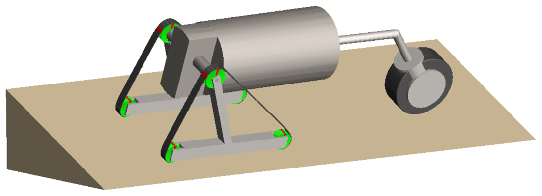
In the critical overturning state, the mechanical arm is controlled to deflect forward along the X axis. Figure 17 shows the simulation experiment of adjusting the deflection angle of the arm on the 25° transverse slope. The results show that the robot gradually enters a stable state during the deflection process of the arm.
By analyzing the simulation process, the change of the normal contact force along the Z axis of the point contact of the robot's non-overturning edge line with time can be obtained, and the overturning stability index can be calculated, as shown in Fig. 18. It can be seen from Fig. 18 that under dynamic conditions, with the increase in the deflection angle of the arm, the overturning stability index of the robot increases first, then does not change significantly, and then increases again, which verifies the correctness of the theoretical analysis and proves the reliability of the adaptive control system.
To physically verify the stability criterion and the effectiveness of the stability control system, the robot platform shown in Fig. 19 is equipped with thin-film pressure sensors (RP-L and RP-CQ18.3) (Lewinger et al., 2006). By designing the structure of the front guide wheel and the track support wheel, the sensors can be embedded. Combined with the previous calculation results, the pressure on the crawler in an unstructured environment can be expressed by multiple point pressures. Therefore, the crawler load-bearing structure is divided into upper and lower layers to install multiple sensors. After processing the measured pressure, the contact force between the robot and the ground can be expressed. The output voltage of the sensors after calibration are directly related to the applied force.
Due to the limitation of experimental conditions, the steel plate is selected as the inclined road surface of the robot in this experiment. However, due to the small adhesion coefficient between the steel plate and the track, to ensure the safety of the experiment, the angle of the slope is set to 15°. The technical parameters of the robot are shown in Table 1. The following experiments are carried out under the condition that the technical parameters of the robot are unchanged.
7.1 Longitudinal slope
The same stage performed in the simulation process is applied to the physical robot. The first stage of the robot runs on a gentle road surface for 5 s. The second stage of the robot climbs a 15° longitudinal slope for 10 s. The third stage is when the robot's leading arm extends on the longitudinal slope for 10 s. In the three stages, the data measured by the sensors are sent to the host computer every second, and the overturning stability index is calculated. Figure 20 shows the three stages of the robot, and Fig. 21 is the comparison of simulation and experimental results.

Figure 20(a) Robots on a flat road; (b) robot climbing; (c) robot on the slope; (d) robot arm elongation.
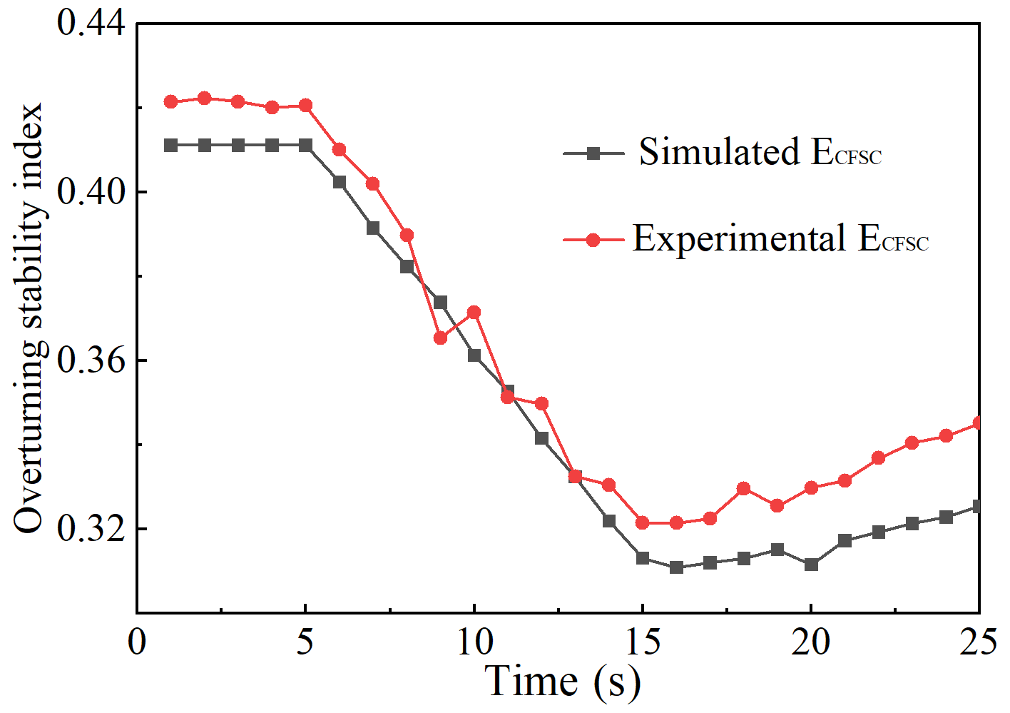
Figure 21The experimental values are compared with the simulation values on the longitudinal slope.
It can be seen from Fig. 21 that the overturning stability index of the robot in the first stage remains at a high value and the change range is small; the stability is good. When the robot moves up the longitudinal slope in the second stage, the center of gravity moves; the force measured by the sensors in contact with the plane becomes larger, and the force in contact with the slope decreases. At the same time, the overturning stability index of the robot decreases, and the stability of the system decreases. At this time, if the overturning stability index of the robot becomes 0, the robot will capsize. In the third stage, the control robot gradually extends the arm out. Currently, due to the forward movement of the center of gravity, the overturning stability index of the robot gradually increases and the stability is improved. The experimental results are consistent with the simulation results, which proves the accuracy of the criterion, indicating that the stability control on the longitudinal slope can improve the stability of the robot.
7.2 Transverse slope
Figure 22 shows the process of the robot driving on a 15° transverse slope and the deflection of the arm to maintain stability. It can be divided into two stages: uphill and deflection of the arm, which lasts for 30 s. The overturning stability index of the robot is calculated by the sensor data. Figure 23 shows the overturning stability index curve with time and the simulation results.
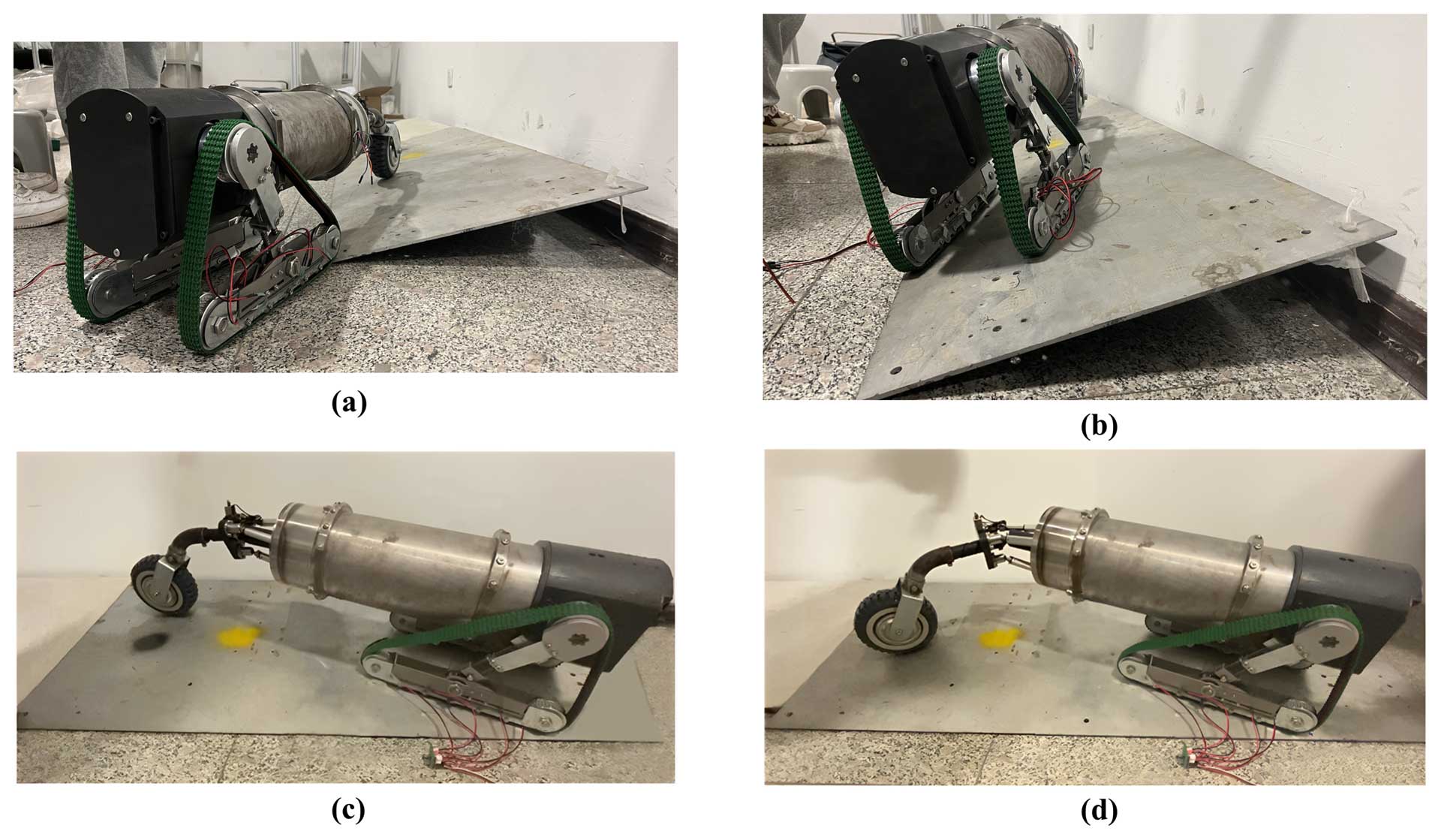
Figure 22(a) Robot climbing; (b) side view of robot on the slope; (c) front view of robot on the slope; (d) robot arm deflection.
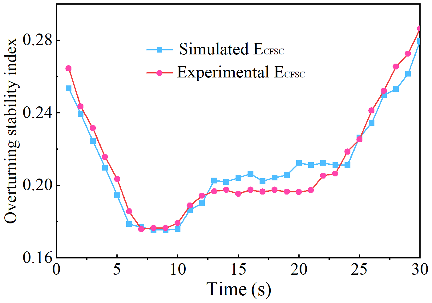
Figure 23The experimental values are compared with the simulation values on the transverse slope.
The experimental results show that the deflection process of the arm on the side slope can be divided into three stages from 10 s onwards. In the first stage, when the deflection angle of the arm is in the range of 0–5°, the overturning stability index of the robot increases gradually with the increase in the deflection angle. In the second stage, when the deflection angle of the arm is in the range of 5–15°, the overturning stability index of the robot does not change significantly. In the third stage, when the deflection angle of the arm is greater than 15°, the overturning stability index of the robot increases gradually with the increase in the deflection angle of the arm. The overturning stability index of the three stages is consistent with the change trend of the simulation curve, and the error is within 5 %. The correctness of the theory is verified, and the effectiveness of the adaptive control system is proved.
-
Aiming at the rescue environment of the 225 mm borehole, a variable structure detection robot for underground rescue was designed by combining a parallel arm and a deformable crawler. The robot can improve stability by changing the configuration of the arm to meet the complex unstructured environment underground.
-
Through the analysis of the working environment of the robot and its own overturning problem, a stability criterion based on the contact force between the robot and the ground was proposed, and the adaptive stability control system of the robot was established by using a the BP neural network.
-
The CFSC was compared with the three existing stability analysis methods to verify the accuracy and efficiency of the method. Based on the criterion, the influence of the stability control system on the dynamic stability of the robot under three typical terrains was analyzed.
-
The simulation model was established. The simulation experiments of the robot on unstructured road and transverse slope road were carried out, and the experimental results were analyzed. The processes of robot climbing longitudinal slope and transverse slope and stability control were carried out by using thin-film pressure sensors. The experimental data were visualized and compared with the simulation results. The results showed that CFSC is consistent with the theoretical analysis and can be used as the evaluation standard of robot stability. The adaptive stability control system can improve the stability of the robot.
All the code and data used in this paper can be obtained upon request to the corresponding author.
Experimental platform: MZ, ZZ, WZ, and XS; data processing: AW; software: AW; validation: HT; writing (original draft preparation): AW, HT, and ML; writing: AW; funding acquisition: HT; supervision: HT; project administration: HT. All authors have read and agreed to the published version of the paper.
The contact author has declared that none of the authors has any competing interests.
The authors would like to thank anonymous reviewers for their valuable comments and suggestions that enabled us to revise the paper.
Publisher’s note: Copernicus Publications remains neutral with regard to jurisdictional claims made in the text, published maps, institutional affiliations, or any other geographical representation in this paper. While Copernicus Publications makes every effort to include appropriate place names, the final responsibility lies with the authors.
The work was supported by the National Natural Science Foundation of China (NSFC) (grant no. 52174149) and the Key Research and Development Program of Shaanxi province (grant no. 2022GY-241).
This paper was edited by Zi Bin and reviewed by four anonymous referees.
Agheli, M. and Nestinger, S. S.: Force-based stability margin for multi-legged robots, Robot. Auton. Syst., 83, 138–149, https://doi.org/10.1016/j.robot.2016.05.012, 2016.
An, Y., Han, T., Zhao, H., and Qiu, S.: Simulation analysis on motion stability of smart wheelchair, J. Phys.-Conference Series, 1873, 012045, https://doi.org/10.1088/1742-6596/1873/1/012045, 2021.
Bachega, R. P., das Neves, G. P., Campo, A. B., and Angelico, B. A.: Flexibility in Hexapod Robots: Exploring Mobility of the Body, IEEE Access, 110454–110471, https://doi.org/10.1109/ACCESS.2023.3321842, 2023.
Chen, G., Xu, Y., Yang, X., Hu, H., Cheng, H., Zhu, L., Zhang, J., Shi, J., and Chai, X.: Target tracking control of a bionic mantis shrimp robot with closed-loop central pattern generators, Ocean Eng., 297, 116963, https://doi.org/10.1016/j.oceaneng.2024.116963, 2024a.
Chen, G., Han, Y., Li, Y., Shen, J., Tu, J., Yu, Z., Zhang, J., Cheng, H., Zhu, L., and Dong, F.: Autonomous gait switching method and experiments of a hexapod walking robot for Mars environment with multiple terrains, Intel. Serv. Robot., 17, 533–553, https://doi.org/10.1007/s11370-023-00508-z, 2024b.
Dai, S. and Jia, X.: Structure Design of Coal Mine Rescue Robot's Swing Arms, Coal Mine Mach., 496–500, 657–661, https://doi.org/10.4028/www.scientific.net/amm.496-500.657, 2010.
Elhosseini, M. A., Haikal, A. Y., Badawy, M., and Khashan, N.: Biped robot stability based on an A–C parametric whale optimization algorithm, J. Comput. Sci.-Neth., 31, 17–32, https://doi.org/10.1016/j.jocs.2018.12.005, 2019.
Erden, M. S. and Leblebiciolu, K.: Torque Distribution in a Six-Legged Robot, IEEE Trans. Robot., 23, 179–186, https://doi.org/10.1109/siu.2006.1659771, 2007.
Ge, L., Fang, Z., Li, H., Zhang, L., Zeng, W., and Xiao, X.: Study of a Small Robot for Mine Hole Detection, Appl. Sci., 13, 13249, https://doi.org/10.3390/app132413249, 2023.
Guo, P.: New progress and new direction of coal mine robot technology, J. China Coal Soc., 48, 54–73, https://doi.org/10.13225/j.cnki.jccs.2022.1661, 2023.
Haikal, A. Y.: Research status and development trend of intelligent mining robot, Gold (1001–1277), 44, 59–68, https://doi.org/10.11792/hj20230910, 2023.
Lewinger, W. A., Branicky, M. S., and Quinn, R. D.: Insect-inspired, Actively Compliant Hexapod Capable of Object Manipulation, DBLP, https://doi.org/10.1007/3-540-26415-9_7, 2006.
Lin, G., Terakawa, T., Shinno, K., Inoue, T., and Komori, M.: RoMop: A New Type of Wheeled Mobile Platform Based on Rotating Locomotion, IEEE/ASME T. Mechatron., 1–12, https://doi.org/10.1109/TMECH.2023.3333016, 2023.
Liu, Y. and Liu, G.: Interaction Analysis and Online Tip-Over Avoidance for a Reconfigurable Tracked Mobile Modular Manipulator Negotiating Slopes, IEEE/ASME T. Mechatron., 15, 623–635, https://doi.org/10.1109/tmech.2009.2031174, 2010.
Maimone, M.: Research progress of mine drilling rescue detection robot, J. Mine Auto., 45, 24–29, https://doi.org/10.13272/j.issn.1671-251x.2018010010, 2019.
Mascarich, F., Nguyen, H., Dang, T., Khattak, S., Papachristos, C., and Alexis, K.: A self-deployed multi-channel wireless communications system for subterranean robots, 2020 IEEE Aerospace Conference, 1–8, https://doi.org/10.1109/AERO47225.2020.9172496, 2020.
Miller, I. D., Cladera, F., Cowley, A., Shivakumar, S. S., Lee, E. S., Jarin-Lipschitz, L., Bhat, A., Rodrigues, N., Zhou, A., Cohen, A., Kulkarni, A., Laney, J., Taylor, C. J., and Kumar, V.: Mine Tunnel Exploration Using Multiple Quadrupedal Robots, IEEE Robot. Auto. Lett., 5, 2840–2847, https://doi.org/10.1109/lra.2020.2972872, 2020.
Polo, J. D. M. and Alcantara, J. H. A.: Stability Analysis Of Locomotion Using Normalized Dynamic Energy Stability Margin For a Hexapod Robot ROMERIN, 2020 IEEE Congreso Bienal de Argentina (ARGENCON), 1–8, https://doi.org/10.1109/ARGENCON49523.2020.9505435, 2020.
Ranjan, A., Panigrahi, B., Sahu, H. B., and Misra, P.: SkyHelp: UAV assisted emergency communication in deep open pit mines, Proceedings of the 1st International Workshop on Internet of People, Assistive Robots and Things, 31–36, https://doi.org/10.1145/3215525.3215537, 2018.
Reher, J. and Ames, A. D.: Dynamic walking: Toward agile and efficient bipedal robots, Annual Review of Control, Robotics, and Autonomous Systems, 4, 535–572, https://doi.org/10.1146/control.2019.2.issue-1, 2021.
Roan, P. R., Burmeister, A., Rahimi, A., Holz, K., and Hooper, D.: Real-World Validation of Three Tipover Algorithms for Mobile Robots, IEEE, 4431–4436, https://doi.org/10.1109/robot.2010.5509506, 2010.
Ryu, S., Won, J., Chae, H., Kim, H. S., and Seo, T.: Evaluation Criterion of Wheeled Mobile Robotic Platforms on Grounds: A Survey, Int. J. Precis. Eng. Man., 25, 1–12, https://doi.org/10.1007/s12541-023-00912-6, 2023.
Song, T., Yang, H., Guo, S., Cui, G., and Yan, Z.: Configuration selection for tipover stability of a modular reconfigurable mobile manipulator under various application situations, Robotica, 41, 1066–1085, https://doi.org/10.1017/S0263574722001424, 2023.
Taheri, H. and Mozayani, N.: A study on quadruped mobile robots, Mech. Mach. Theory, 190, 105448, https://doi.org/10.1016/j.mechmachtheory.2023.105448, 2023.
Tian, H. and Fang, Z.: Analysis and Control for Tumble Stability of Wheel-Legged Robots, Robot, 31, 7, https://doi.org/10.3321/j.issn:1002-0446.2009.02.010, 2009.
Toupet, O., Biesiadecki, J., Rankin, A., Steffy, A., Meirion-Griffith, G., Levine, D., Schadegg, M., and Maimone, M.: Terrain-adaptive wheel speed control on the Curiosity Mars rover: Algorithm and flight results, J. Field Robot., 37, 699–728, https://doi.org/10.1002/rob.21903, 2020.
Uno, K., Ribeiro, W. F., Jones, W., Shirai, Y., Minote, H., Nagaoka, K., and Yoshida, K.: Gait planning for a free-climbing robot based on tumble stability, 2019 IEEE/SICE International Symposium on System Integration (SII), 289–294, https://doi.org/10.1109/sii.2019.8700455, 2019.
Wong, J. Y., Jayakumar, P., and Preston-Thomas, J.: Evaluation of the computer simulation model NTVPM for assessing military tracked vehicle cross-country mobility, P. I. Mech. Eng. D.-J. Aut., 233, 1194–1213, https://doi.org/10.1177/0954407018765504, 2019.
Yan, Z.: Research status and development of robotization of coal mine roadheader, J. China Coal Soc., 45, 2995–3005, https://doi.org/10.13225/j.cnki.jccs.2019.1452, 2020.
Zhao, J., Zhang, J., Liu, H., Wang, J., and Chen, Z.: Path planning for a tracked robot traversing uneven terrains based on tip-over stability, Asian J. Control, 25, 3569–3583, https://doi.org/10.1002/asjc.3048, 2023.
Zhu, D., Sun, X., Liu, S., and Guo, P.: A SLAM method to improve the safety performance of mine robot, Safety Sci., 120, 422–427, https://doi.org/10.1016/j.ssci.2019.07.015, 2019.
- Abstract
- Introduction
- Introduction of a variable structure detection robot for underground rescue
- Analysis of the robot overturning stability problem
- Stability criteria and control method
- Validation
- Simulation experiment
- Experimental validation
- Conclusions
- Code and data availability
- Author contributions
- Competing interests
- Acknowledgements
- Disclaimer
- Financial support
- Review statement
- References