the Creative Commons Attribution 4.0 License.
the Creative Commons Attribution 4.0 License.
 | 25 Jul 2024
Design and motion analysis of a new wheeled rolling robot
Hui Bian
Chang-Qian Meng
Because the wheeled rolling robot has the characteristics of fast movement, high work efficiency and strong bearing capacity, it can be applied to industrial production and detection. Aiming at the problems of low motion efficiency and a large number of drivers of rolling robots based on the parallel mechanism, a new type of wheeled rolling robot composed of a planar 3-RRR parallel mechanism and a spoke-type variable-diameter wheel is proposed in this paper. By adjusting the output of the 3-RRR parallel center of gravity adjustment device, the robot can deform and roll. In this paper, the spoke-type variable-diameter wheel is designed and the eccentric torque workspace of the 3-RRR parallel center-of-gravity adjustment device is optimized. On the basis of clarifying the relationship between wheel diameter scaling and input angle, the kinematic and dynamic models of the wheeled rolling robot are established and simulated by Adams. Finally, the prototype was built and the experiments were carried out. The results show that the wheeled rolling robot has the ability to linearly roll, turn and climb at small angles.
- Article
(17915 KB) - Full-text XML
- BibTeX
- EndNote


The application of mobile robots is becoming more and more extensive, and it has been replacing human beings in different fields and playing an increasingly important role. As a special mobile robot, the rolling robot changes the torque of the support point by the continuous adjustment of the center of mass inside the structure to realize rolling. Due to its high flexibility, strong stability and low energy consumption, it has developed rapidly in the field of reconnaissance and exploration (Sabet et al., 2020).
Common rolling robots are mostly spherical. The driving devices of spherical rolling robots are mainly divided into two categories: movable slider and pendulum mechanism (Ho et al., 2015; DeJong et al., 2017; Wu et al., 2021). In order to enhance the stability and obstacle-surmounting ability of the spherical rolling robot, a high-speed flywheel can be installed on both sides of the pendulum mechanism or two spherical rolling robots can be connected by a mechanical coupling device (Hu et al., 2021; Sagsoz and Eray, 2023). Considering that the abovementioned rolling robot will slide relative to the ground during the start or stop phase, Karavaev et al. (2015) adopted the Mecanum wheel to drive the inner wall of the spherical shell to improve the whole process stability of the system. Tafrishi et al. (2019) developed a fluid-driven spherical rolling robot. Since two mutually perpendicular hydraulic pipes are connected to the surface of the spherical shell, other sensor components can be installed in the center of the spherical shell. In addition, there is a special kind of spherical rolling robot. Kim et al. (2020) designed a cable-driven spherical tensegrity robot, but the control method of this kind of rolling robot is not yet mature, and its application value is limited. The spherical rolling robot has high flexibility in motion, but the modeling and control are complex, and the energy consumption of motion is large (Bai et al., 2018; Belzile et al., 2022; Li et al., 2023). In addition to spherical rolling robots, wheeled rolling robots are also the focus of current research. The deformation of the wheel structure enables the robot to have multiple motion modes at the same time, which improves the adaptability of the robot to the environment, especially regarding the obstacle-surmounting ability of the robot (Phipps et al., 2008; Miura et al., 2019; Zhang et al., 2020). Wang et al. (2016) designed a reconfigurable modular robot that can smoothly switch between snake gait mode and chain rolling mode. Sastra et al. (2009) improved the maximum speed of the planar rolling by controlling the shape of the reconfigurable modular robot in the chain rolling process. Similarly, Wang et al. (2018) proposed a rolling robot based on a closed five-arc bar mechanism, which also smoothly rolls by changing the shape of the cylinder. With the rapid development of material science and actuator technology, Misu et al. (2018) designed a miniature wheeled rolling robot that can jump while rolling using highly elastic materials and micro motors. Mao et al. (2022) proposed a fluidic rolling robot driven by a simple electrohydrodynamic (EHD) pump. Its biggest feature is that it is almost silent when rolling. The soft closed-chain rolling robot is a new research direction. Its wheels are mostly made of dielectric elastomer actuators or modular unidirectional shape memory alloy (SMA) actuators (Li et al., 2021; Mansour et al., 2020). Such robots have good environmental adaptability, but their motion speed is much lower than that of rolling robots driven by rigid actuators.
Recently, irregular rolling robots have gradually also been developed. The most common type is a rolling robot composed of various forms of connecting rods (Liu et al., 2020a). The linkage rolling robot enhances its adaptability to the environment through its own complex deformation (Tian et al., 2021). Liu et al. (2020b) designed a novel reconfigurable rolling robot based on a single-loop closed-chain four-bar mechanism. It has four motion modes: four-bar walking, four-bar rolling, self-deformation and six-bar rolling, but the rolling speed is slow. Cheng et al. (2022) proposed a double four-link wheeled rolling robot, which can switch between crawler rolling mode and crawling mode and has fast rolling and strong obstacle-surmounting abilities. Tian and Yao (2015) proposed a triangular bipyramid rolling robot. Because the robot can change its rolling step size and its own width during the rolling process, it can roll through a narrow channel. Wang et al. (2021) designed a tetrahedral mobile robot with only rotating joints, which has good working space and small displacement error. The linkage rolling robot has strong obstacle-surmounting ability, but there are some problems, such as low motion efficiency, weak bearing capacity and poor stability (Ding et al., 2015; Hao et al., 2020). Considering that the parallel mechanism has large bearing capacity, high motion accuracy and good stability, it can be used as the actuator of machine tools and spraying equipment (Wu et al., 2017, 2018). In addition, parallel mechanisms with large deformation capabilities are often used for structural innovation of rolling robots (Li et al., 2017). Ping et al. (2022) designed a parallel rolling robot with a deployable platform that can realize folding motion, quadrilateral rolling and hexagonal rolling, but its motion speed is low. In order to improve the rigidity and power output of the rolling robot, Shen et al. (2017) proposed a hydraulically driven 3-DOF parallel rolling robot. Wei et al. (2019) designed a modular rolling robot composed of 12 planar RRR chains, but the control of the robot is complex, and the number of actuators is too large.
Aiming at the problems of low speed and a large number of drivers of rolling robots based on the parallel mechanism, this paper proposes a new type of wheeled rolling robot composed of a planar 3-RRR parallel mechanism and the spoke-type variable-diameter wheel. The research of Wu et al. (2010) and Zhang and Zhang (2016) showed that the kinematic and dynamic performance of the redundantly actuated 4-RRR parallel mechanism is better than that of the fully actuated 3-RRR parallel mechanism. However, according to the analysis in Sect. 2.4 of this paper, with the increase in the percentage of the mass of the moving platform to the total mass of the rolling robot, the swing angle required to start the rolling robot is smaller; that is, the use of a fully driven 3-RRR parallel mechanism will make starting the variable-wheel-diameter rolling robot easier. In addition, compared with 3-PRR and 3-RPR, the 3-RRR parallel mechanism has higher dexterity and energy transfer efficiency (Si et al., 2022). Therefore, it is reasonable to choose the planar 3-RRR parallel mechanism as the power device of the variable-wheel-diameter rolling robot. This paper mainly includes five parts. Section 1 introduces the research status of rolling robots. Section 2 is the structural design of wheeled rolling robots. Sections 3 and 4 establish the kinematic and dynamic models of the system and use Adams for simulation. Section 5 builds a prototype and carries out experiments.
2.1 Overall design
Inspired by the cylinder that makes a rolling motion, when the two wheels of the wheeled rolling robot have the same diameter, linear rolling can be achieved. When the diameters of the two wheels are different, the turning can be achieved, and the turning angle is only related to the difference in diameter. Therefore, the difficulty of the design of the wheeled rolling robot becomes the design of the variable-diameter wheel and its driving mode. Based on this idea, this paper designs a wheeled rolling robot, including a spoke-type variable-diameter wheel and a planar 3-DOF parallel mechanism, as shown in Fig. 1.
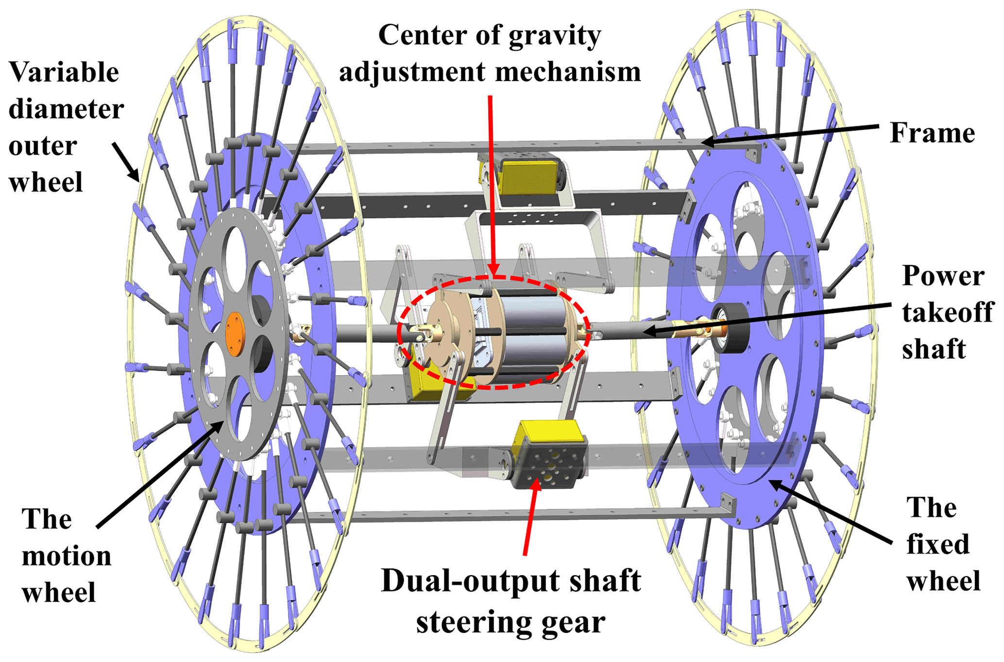
The wheeled rolling robot is composed of three parts: the frame, the center of gravity adjustment device based on a 3-RRR parallel mechanism and the spoke-type variable-diameter wheel. The frame connects two spoke-type variable-diameter wheels with opposite angles and serves as the base of the 3-RRR parallel mechanism. The moving platform of the 3-RRR parallel mechanism is connected to the drive shaft of the spoke-type variable-diameter wheel by two retractable universal joint couplings. Among them, the moving platform of the 3-RRR parallel mechanism has one rotational DOF and two translational DOF in the plane. When the moving platform of the 3-RRR parallel mechanism rotates, one diameter of the spoke-type variable-diameter wheel increases and the other diameter decreases and then the wheeled rolling robot turns. When the moving platform of the 3-RRR parallel mechanism moves, the wheeled rolling robot makes a rolling motion.
2.2 Design of the spoke-type variable-diameter wheel
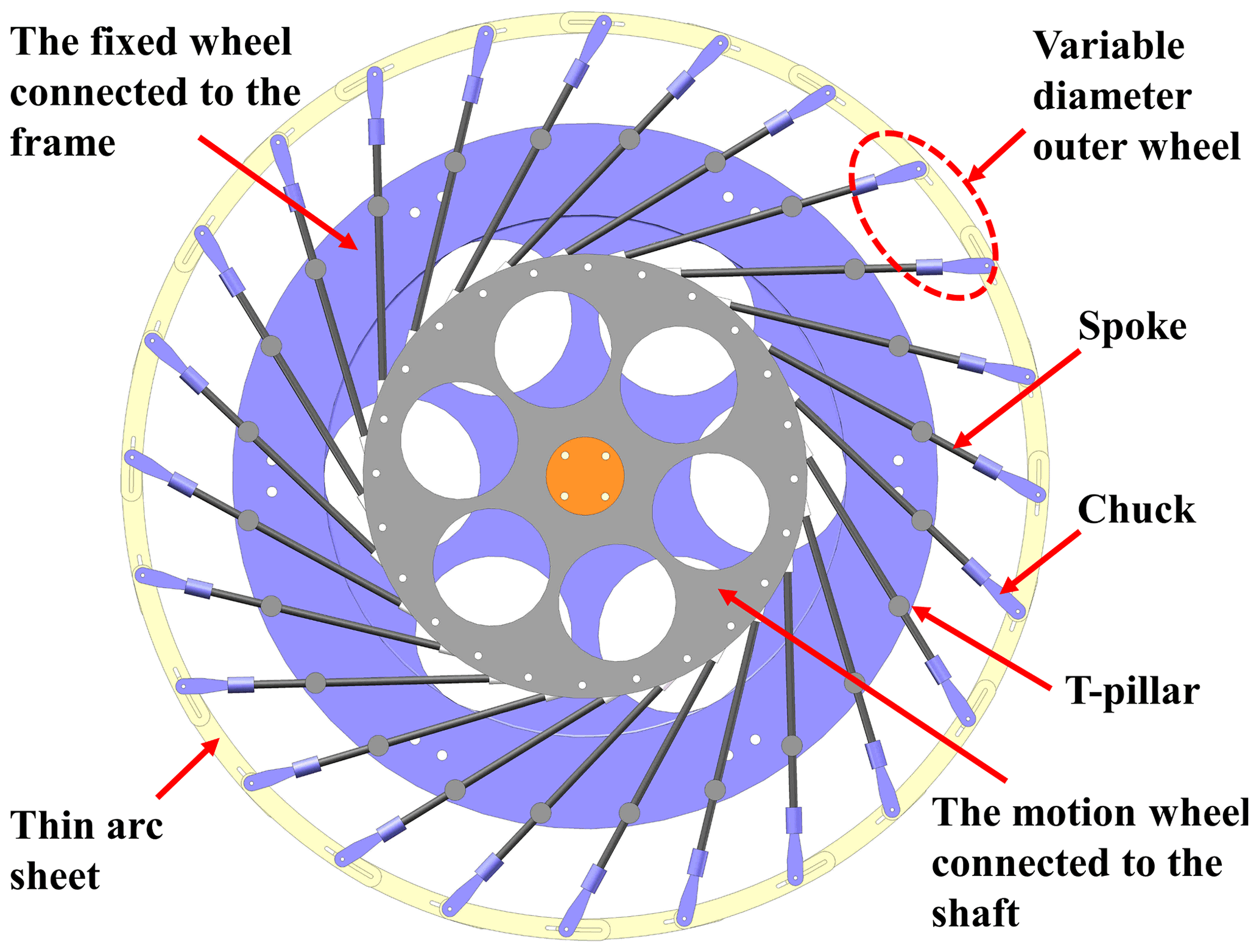
The spoke-type variable-diameter wheel is mainly composed of the motion wheels connected to the shaft, the fixed wheels connected to the frame and the variable-diameter outer wheels, as shown in Fig. 2. Among them, the arc sheets of the same specification are staggered and stacked in the front and back, the left side of the arc sheet is provided with a chute of the same specification, the right side is connected with the chute of the adjacent arc sheet by the chuck, and the other end of the chuck is connected with the spoke to form a variable-diameter outer wheel. The bottom end of the spoke is fixedly connected with the ball joint bearing that is evenly distributed on the motion wheel to realize the connection between the variable-diameter outer wheel and the motion wheel, then the spoke is passed through the perforated T joint to connect the variable-diameter outer wheel with the fixed wheel, and finally the spoke-type variable-diameter wheel is formed. In order to solve the balance problem of the variable-diameter outer wheel of the robot in the non-rolling state and avoid the contraction of the spoke group under the influence of gravity, three sets of supporting springs are arranged between the motion wheel and the fixed wheel.
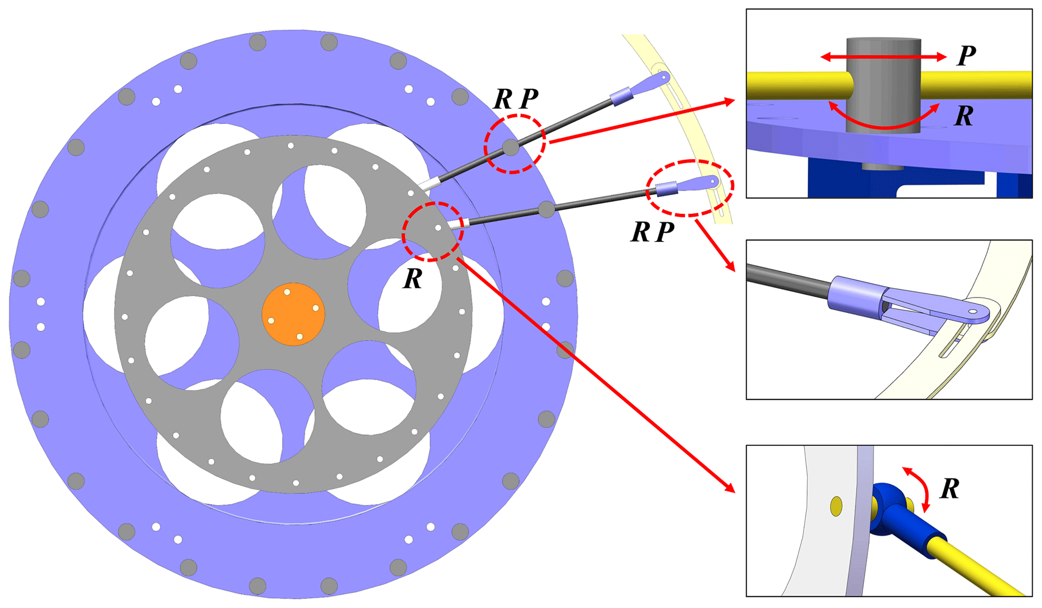
The single-branch structure of the variable-diameter outer wheel is shown in Fig. 3. It can be seen from the figure that the joint between the spoke and the motion wheel, the joint between the T joint and the fixed wheel, and the joint between the chuck and the outer arc sheet are all revolute pairs. The connection between the spoke and the T joint and the connection between the chuck and the arc sheet each contain a moving pair. The outer chuck tightly connects to the adjacent arc sheet so that the arc sheet is always compactly arranged during the scaling process of the spoke-type variable-diameter wheel. The robot maintains a stable posture during the movement, and there is no flutter and instability due to the cooperation between components.
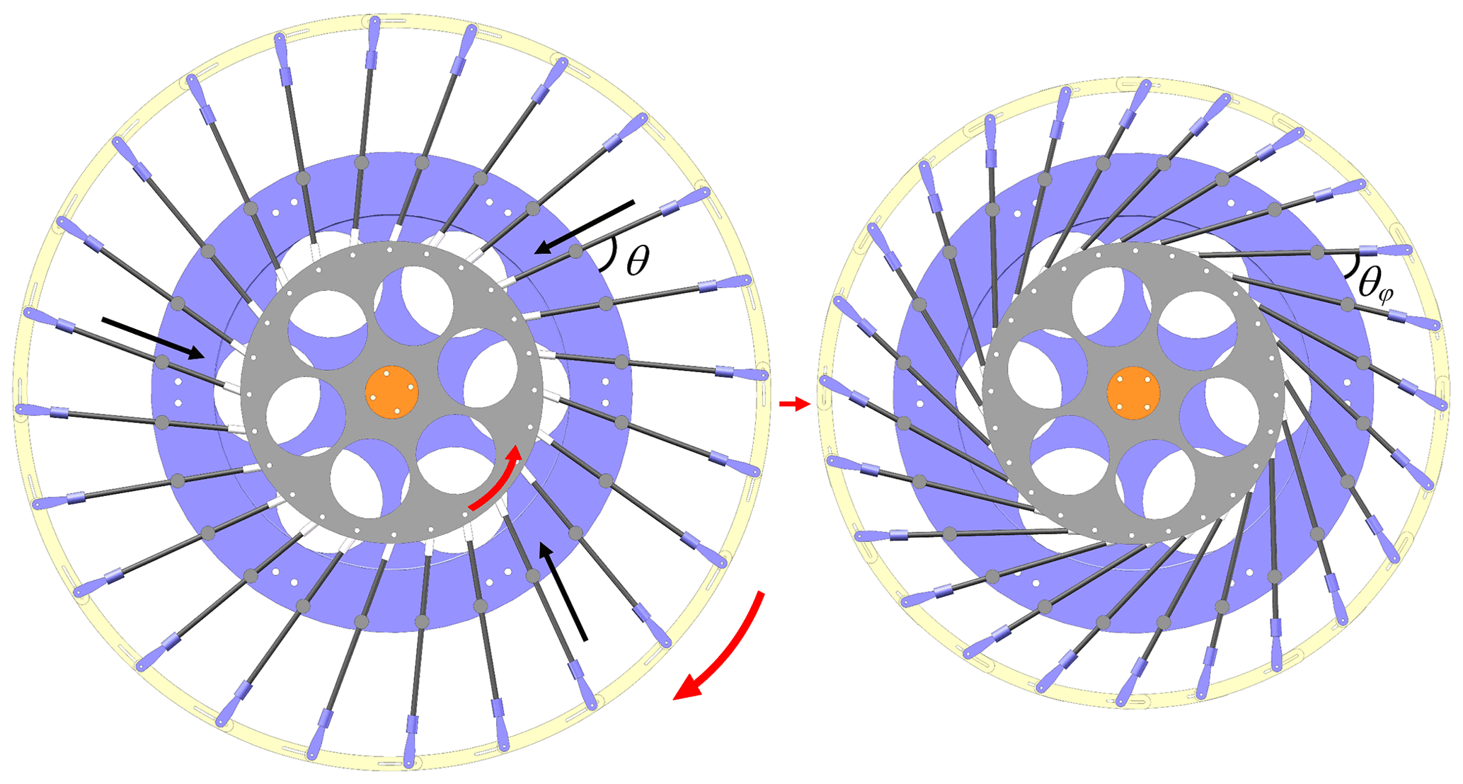
The scaling of the robot's wheel diameter is driven by the rotation of the motion wheel, which in turn drives the angle change in the spokes. The spokes are constrained by the T joint and scale along the channel direction, pulling the outer arc sheet to make the scaling motion. Taking the contraction motion of the spoke-type variable-diameter wheel as an example, when the drive shaft drives the motion wheel to rotate in the counterclockwise direction, the motion wheel drives the spoke to rotate and the spoke shrinks along the T joint so that the outer chuck slides along the clockwise direction of the arc slide to complete the contraction. Figure 4 is the overall shrinkage change diagram of the robot wheel diameter.
2.3 Optimization of the eccentric torque workspace
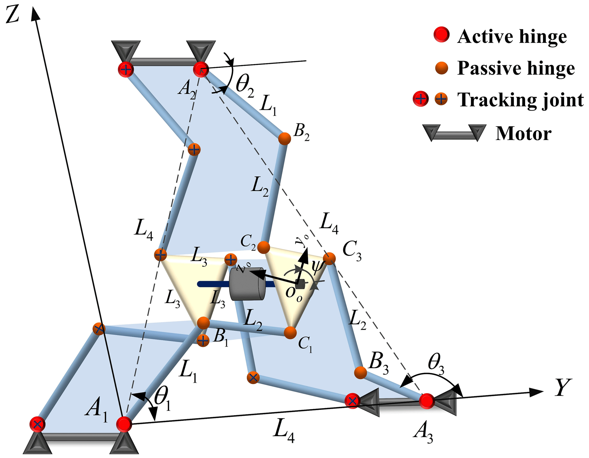
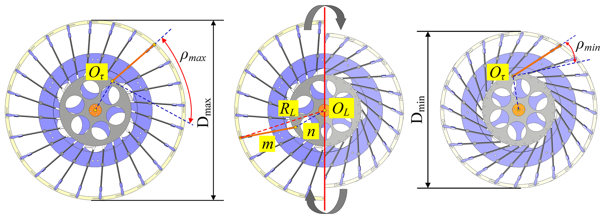
Based on the advantages of a parallel mechanism with a lower DOF, such as strong bearing capacity, high flexibility and lower number of actuators, this paper proposes a 3-RRR parallel center-of-gravity adjustment device as shown in Fig. 5. The driving principle of the center-of-gravity adjustment device is briefly summarized as the eccentric torque generated by the center of gravity offset that destroys the equilibrium state of the system, and the robot rolls when it loses balance. When the moving platform of the 3-RRR parallel mechanism maintains a fixed angle during the movement, the eccentric torque workspace of the robot changes.
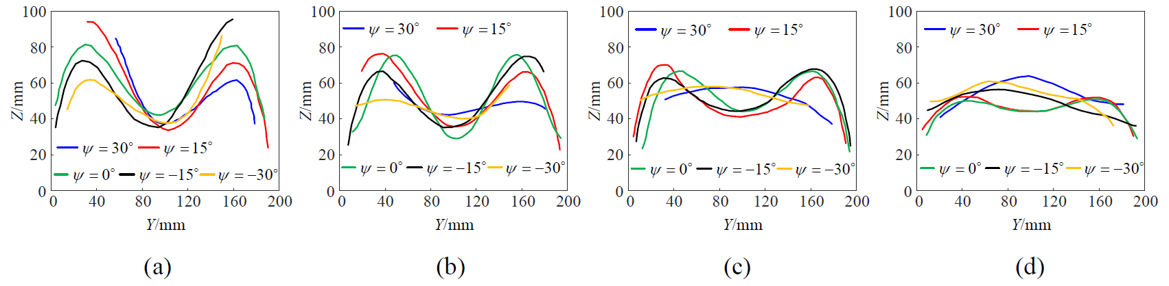
Under the premise that the frame size is determined, the installation size of the steering gear base arranged around the frame is fixed. In addition, the 3-RRR parallel center-of-gravity adjustment device satisfies L1≤L2 and mm. As the rod length changes, the eccentric torque workspace changes. In order to find out the best rod length ratio parameter, L1:L2, and obtain the optimal eccentric torque driving space, the simulation operation test of the mechanism is carried out. The sizes of L1 are 50, 60, 70 and 80 mm, and the corresponding sizes of L2 are 110, 100, 90 and 80 mm. Therefore, the four groups of rod length ratio parameters are (5:11)1, (3:5)2, (7:9)3 and (1:1)4. Then, the variation law of the defects of the eccentric torque workspace with the rod length ratio parameters is explored. By observing the space point set of the motion of the center-of-gravity adjustment device, it is found that in the range of [−30, 30]°, the eccentric torque workspace is irregularly incomplete. The eccentric torque workspace of the moving platform rotation angle ψ at 30, 15, 0, −15, −30° is intercepted, respectively, and the change trend of the eccentric torque workspace is calculated as shown in Fig. 6.
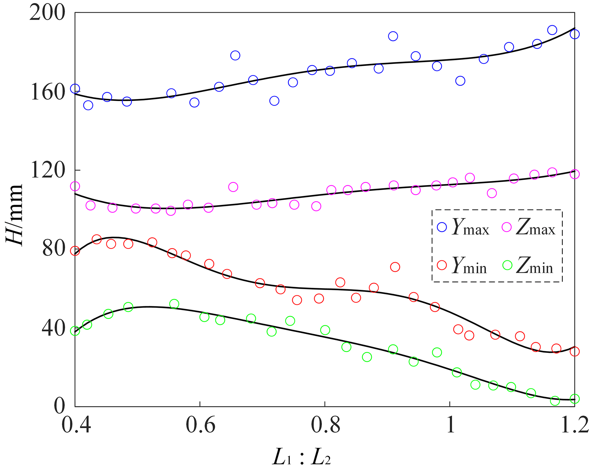
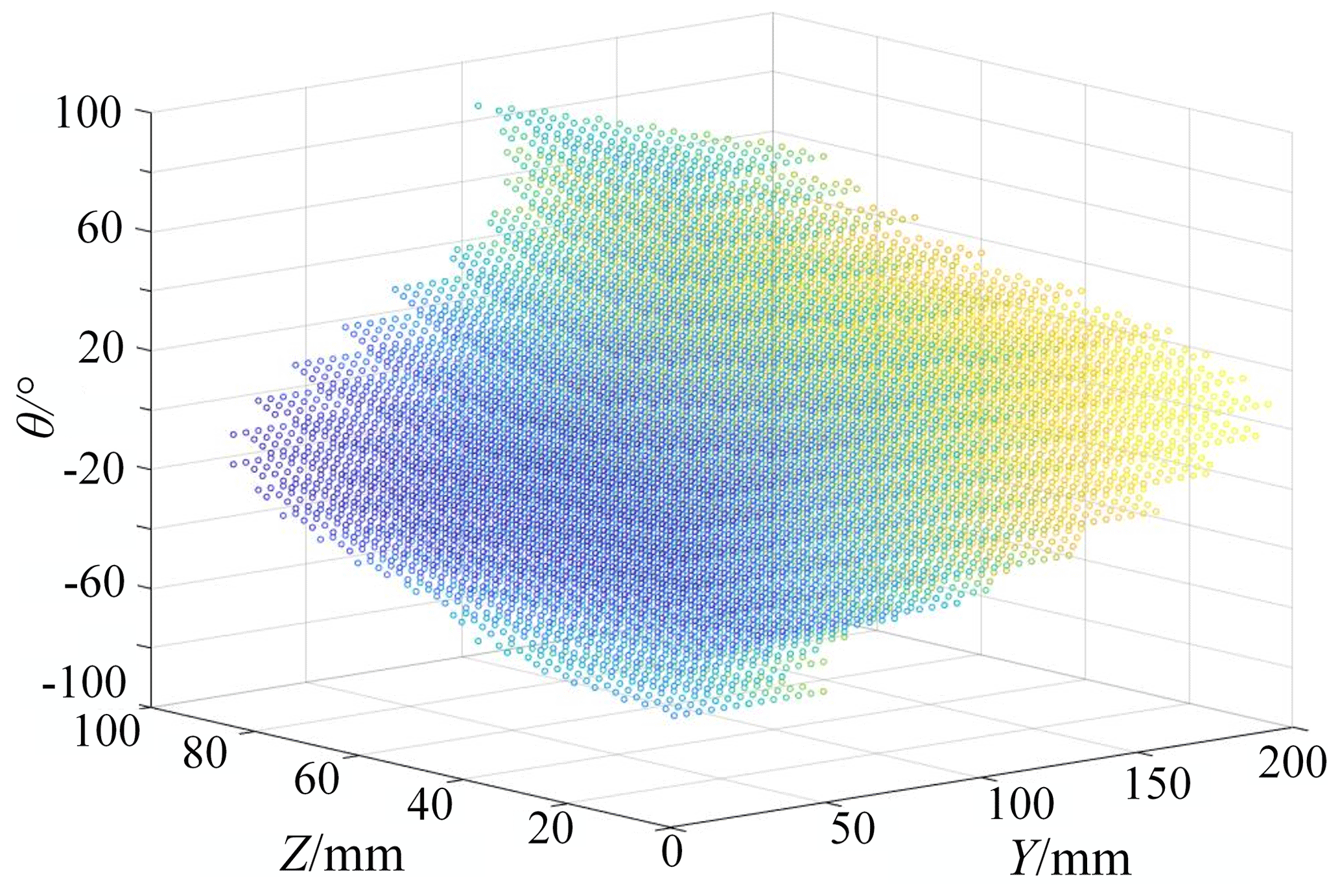
The results show that when , the change trend of the eccentric torque workspace is relatively smooth and stable, and the movement of the 3-RRR parallel gravity-center adjustment device is the most stable and smooth. In order to extract the boundary points of the eccentric torque workspace, the limit position of the moving platform of the mechanism is determined based on the inverse kinematics of the mechanism and the search optimization method. We organize the data and draw the boundary extreme point change curve of the eccentric torque workspace as shown in Fig. 7. With the increase in rod length ratio parameters, Ymax and Zmax show an upward trend, and Ymin and Zmin show a downward trend; that is, the limit of the working space of the moving platform increases with the increase in rod length ratio parameters. Considering the change trend of the eccentric torque workspace and the limit of the workspace of the moving platform, the rod length, mm, is determined. On this basis, the optimized eccentric torque workspace is shown in Fig. 8. The working space of the eccentric torque in Fig. 8 is regular and continuous, which indicates that the 3-RRR parallel gravity-center adjustment device has good smoothness of motion and good transmission performance of eccentric torque, and the robot can obtain uninterrupted driving torque support during rolling.
2.4 Analysis of the moving platform
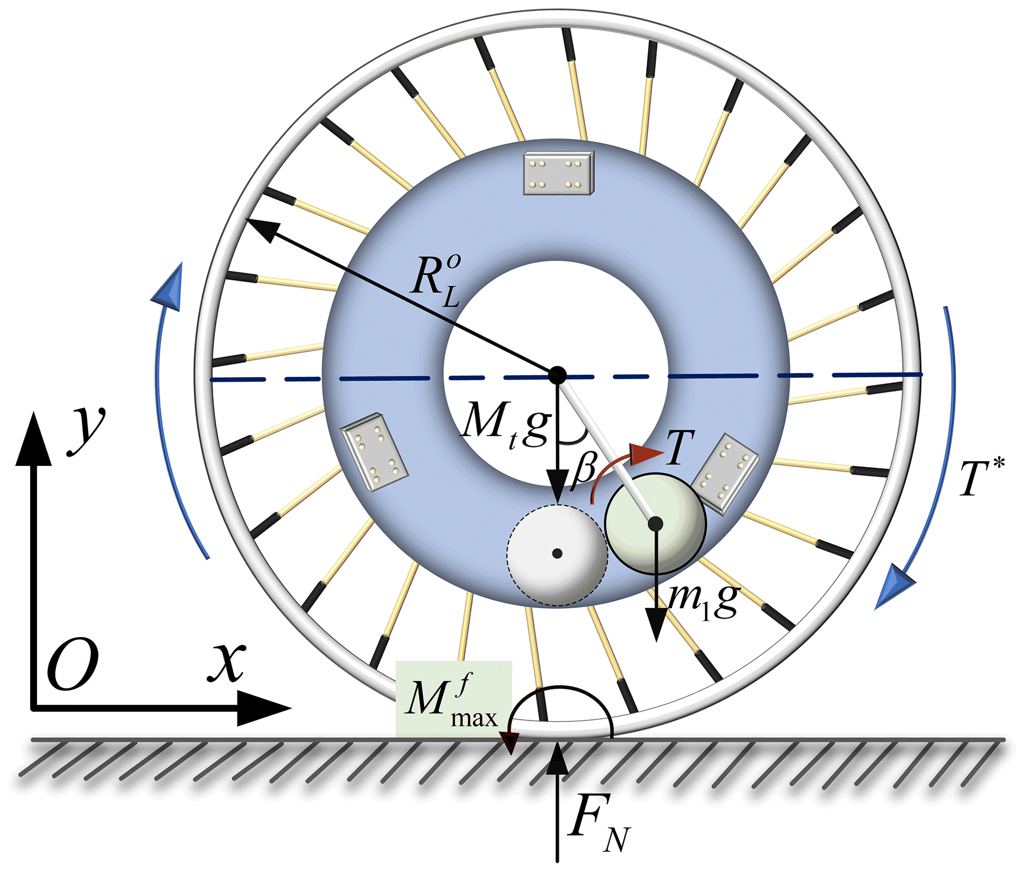
The rolling of the robot is caused by the eccentric torque generated by the movement of the center-of-gravity adjustment device to overcome the rolling friction torque between the variable-diameter outer wheel and the ground. The power of the wheeled rolling robot is provided by three double-output shaft-steering engines evenly distributed on the frame. When the driving force, F∗, of the robot is small and the robot has a tendency to roll, the variable-diameter outer wheel makes contact with the ground and squeezes the ground to produce contact deformation, and the constraint reaction force at the wheel edge is nonlinearly distributed. Figure 9 is the mechanical model of the robot. As the driving force, F∗, increases, when the rolling torque, T∗, generated by the driving force, F∗, and the ground distribution force system is greater than the maximum rolling friction torque, , of the robot (that is, ), the robot begins to roll. The moving platform of the gravity-center adjustment device is used to carry components such as battery packs, controllers and sensors. The mass and volume of the battery pack are the main considerations in the design of the moving platform. In the case of a certain rod length ratio parameter of the center-of-gravity adjustment device, the eccentric torque is positively correlated with the sine function of the swing angle of the mechanism. Therefore, the following applies:
In Eq. (1), μ is the rolling friction coefficient, Mt is the total weight of the robot, m1 is the equivalent mass of the center of gravity adjustment device and β is the swing angle of the parallel mechanism rod group. If the mass ratio is and the parameter is mm, then Eq. (1) can be expressed as
Therefore, the larger the mass ratio, km, the smaller the swing angle, β, required for the wheeled rolling robot to start moving and the better the maneuverability of the robot. Improving the equivalent mass of the center-of-gravity adjustment device can make the robot begin to move when the swing angle is small.
3.1 Analysis of wheel diameter scaling
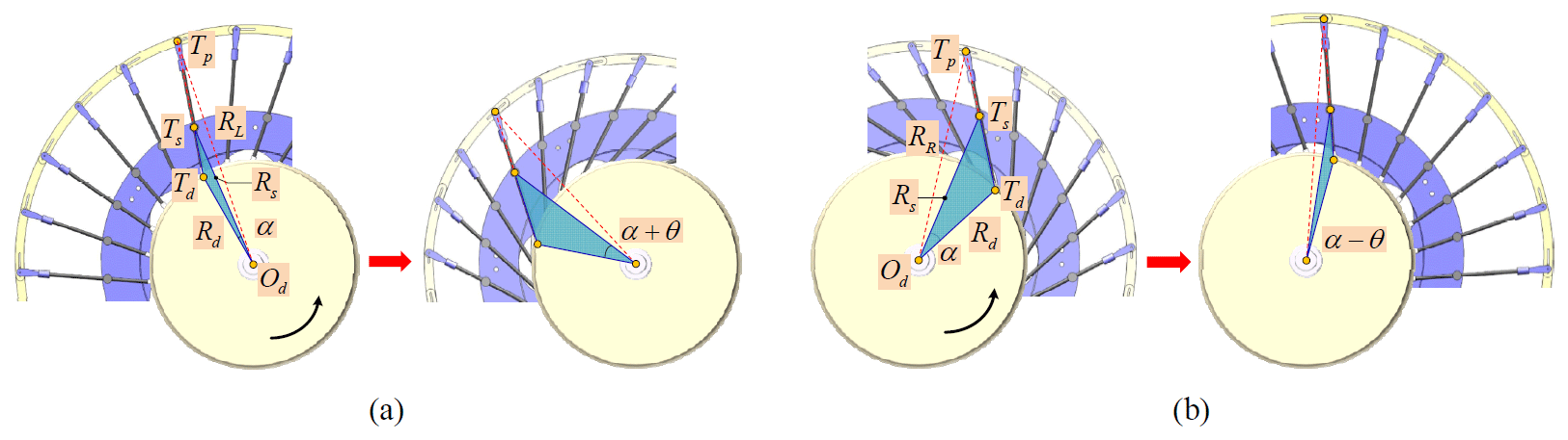
The spoke-type variable-diameter wheel is connected to the 3-RRR parallel center-of-gravity adjustment device by a symmetrically arranged retractable universal joint, and the motion wheel and the fixed wheel are connected by spokes. Then, the relationship between the wheel diameter and the spoke scaling angle in the deformation process of the wheeled rolling robot is analyzed. Taking the left turn of the robot as an example, the initial wheel diameter of the variable-diameter outer wheel is R1. When the center-of-gravity adjustment device rotates at an angle θ, it is transmitted to the motion wheels on both sides through the universal shaft to drive the spoke change. Because the spoke groups of the variable-diameter wheel train on both sides are arranged in reverse, the left spoke shrinks under the drive of the motion wheel, the outer wheel diameter is reduced to R2, the right spoke is opened and the outer wheel diameter is expanded to R3. After the wheel diameter changes, the robot continues to roll in the counterclockwise direction. Because the left-wheel diameter is small and the right-wheel diameter is large, the rolling robot turns left. The scaling process of the wheel diameter of the rolling robot is shown in Fig. 10. The center of the circle is defined as Od, the connection point between the bottom of the spoke and the edge of the motion wheel is Td, the connection point between the middle of the spoke and the T joint is Ts, and the connection point between the top of the spoke and the arc sheet is Tp. In addition, the radius of the motion wheel is defined as Rd, the radius of the fixed wheel is Rs, and the radius of the left and right variable-diameter outer wheels is RL and RR, respectively. If |TdTs|=m1, |TdTp|=m and ∠TdOdTs=α, in ΔTdOdTs, the relationship between the side lengths can be expressed as
Let ∠OdTdTs=β. Then
And in the triangle ΔTdOdTp, the following applies:
Therefore, the combined Eqs. (4) and (5) can be obtained:
According to Eq. (6), the radius, RL, of the variable-diameter outer wheel of the robot is only related to the input angle, α, of the motion wheel. Because the parameters of the wheel train on both sides of the robot are the same when the robot is rolling in a straight line, the following also applies:
As shown in Fig. 10a, when the motion wheel turns over the angle θ, the robot's left variable-diameter wheel train shrinks and the position of each reference point changes. It can be seen that the blue triangle area increases significantly, the spoke group shrinks counterclockwise, and the arrangement is more compact. Similarly, the following can be obtained:
When , , 2mRdRs=C, , 2RdRs=E, Eq. (8) can be simplified as
As shown in Fig. 10b, when the motion wheel turns over the angle θ, the robot's right variable-diameter gear train opens, the spoke group opens counterclockwise and forms a radial shape, and the blue triangle area shrinks. Similarly, the following can be obtained:
Equations (9) and (10), respectively, represent the change in the radius of the left and right wheels after the motion wheel rotates at a certain angle. The scaling of the variable-diameter outer wheel of the wheeled rolling robot is only related to the input angle of the motion wheel.
3.2 Analysis of linear rolling and turning motion
The linear rolling ability of the wheeled rolling robot is determined by the size of the eccentric torque provided by its center-of-gravity adjustment device and the scaling size of the variable-diameter outer wheel. As shown in Fig. 11, the ratio of the larger wheel diameter size to the smaller wheel diameter size of the variable-diameter outer wheel of the wheeled rolling robot in the turning state is defined as the scaling ratio, and the scaling ratio represents the turning motion ability of the robot. The angle between the spoke and the tangent of the motion wheel is defined as the scaling angle of the variable-diameter outer wheel, and the scaling angle represents the deformation ability of the robot. The wheel diameter size is defined as when walking in a straight line, and the size range satisfies . The radius of the moving wheel is n, and the length of the spoke is m. According to the cosine theorem, the radius of the outer wheel with a variable diameter is
Considering that the wheeled rolling robot makes a pure rolling motion and does not sideslip, the kinematic equation of the wheeled rolling robot based on the nonholonomic system theory is listed as follows:
When , the following applies:
According to the matrix operation, A−1 is obtained, and the inverse kinematics matrix equation of the wheeled rolling robot is
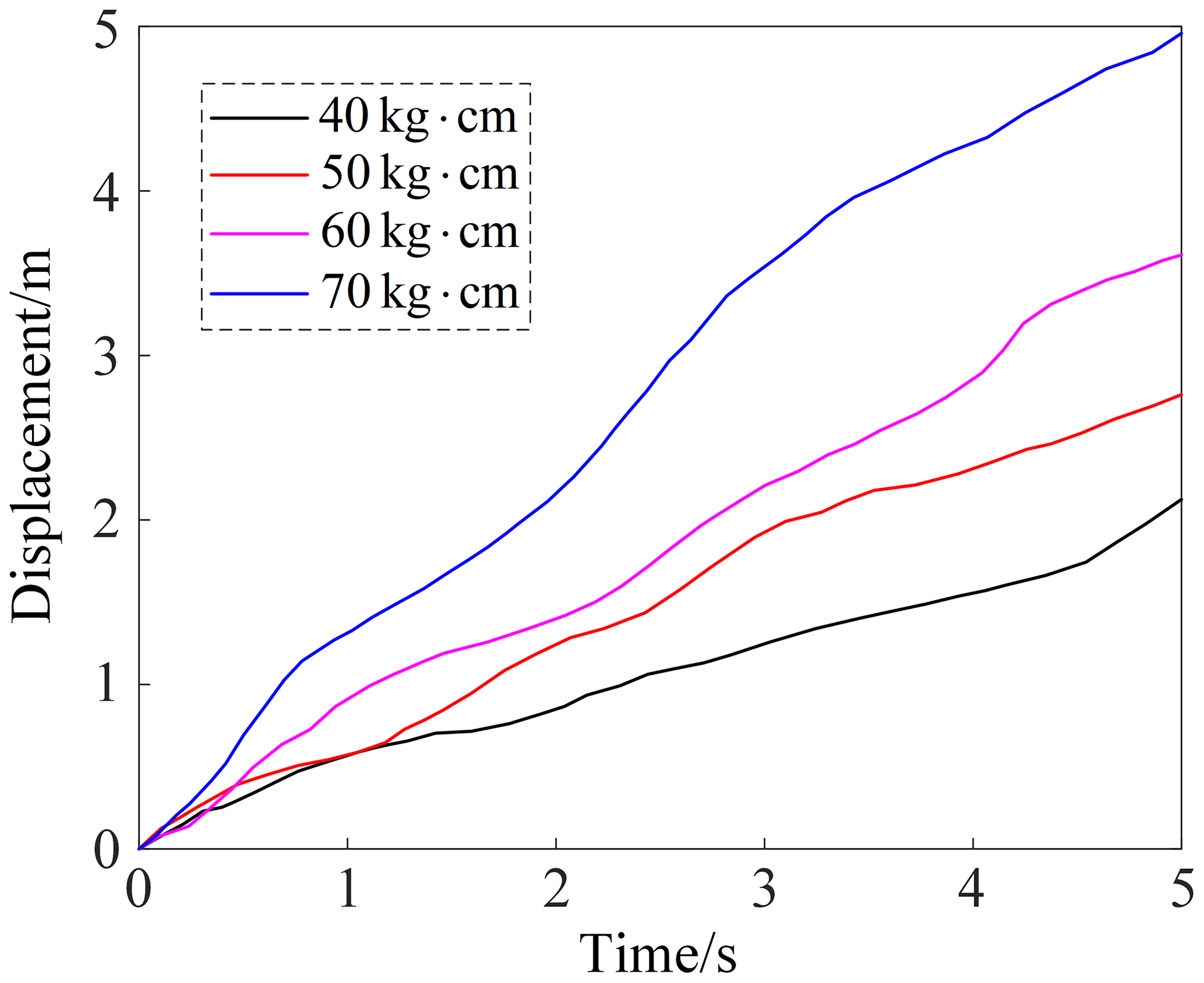
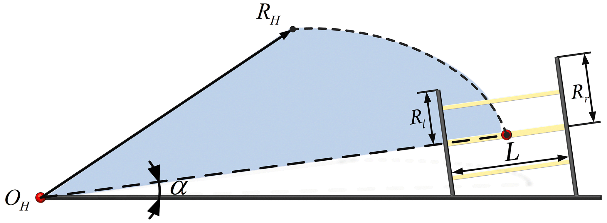
Adams is used to simulate the linear rolling of the wheeled rolling robot. Figure 12 is the displacement curve of the wheeled rolling robot when the dual-output shaft-steering gear outputs with different torques. The simulation results show that the maximum speed of the robot rolling on the horizontal ground is about 1 m s−1. The state of the turning motion of the wheeled rolling robot is shown in Fig. 13. At this time, the left wheel of the robot shrinks and the right wheel opens to complete the left-turn motion. The inclination angle of the turning state of the robot is defined as α. The larger the inclination angle, the smaller the turning radius of the robot and the more flexible the movement. According to the geometric relationship, the robot inclination angle is
The turning radius of the robot is
If the linear velocity of the whole turning of the robot is ν and the angular velocity is ω, the linear velocities of the left and right wheels of the robot are
3.3 Analysis of climbing motion
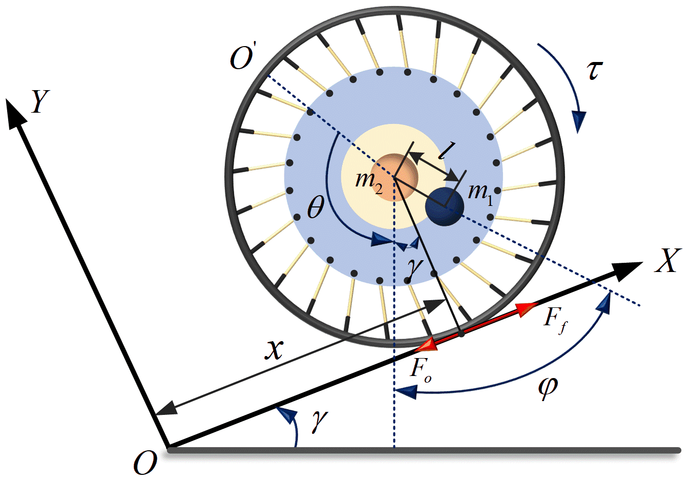
In the process of the climbing motion, the wheeled rolling robot easily enters an unstable state due to the influence of gravity and slope friction. Therefore, when analyzing the climbing motion of the wheeled rolling robot, this paper defaults to the fact that the variable-diameter outer wheel is a rigid body, and carries out a pure rolling motion without the sideslip phenomenon. The mass of the robot system is divided into two parts. The mass of the center of gravity adjustment device is m1, the mass of the other parts is m2, and the radius of the variable-diameter outer wheel is R. As shown in Fig. 14, the wheeled rolling robot moves on the slope with an inclination angle of γ, the rotation angle of the variable-diameter outer wheel is θ, the angle between the center-of-gravity adjustment device and the vertical direction is φ, and the eccentric torque of the robot is τ. The friction between the slope and the robot's variable-diameter outer wheel is greater than the force along the slope of the robot system. The force condition of the wheeled rolling robot moving uphill is
The generalized coordinate method is used to analyze the motion constraint equation of the slope the robot is on. The constraint equation of the robot on the slope can be written as
The integral of Eq. (20) shows that the kinematic equation of the whole system can be expressed by the rotation angle, θ, of the variable-diameter outer wheel and the angle φ between the center-of-gravity adjustment device and the vertical direction. The generalized coordinates of the system are selected as
The Lagrange function of the robot system is
Since the eccentric torque of the robot is τ, the Lagrange equation of the system can be expressed as
It can be seen from Eq. (23) that the robot system is an underactuated system with input coupling, and its nonholonomic constraint equation needs to be established by dynamic modeling. Because and , the constraint relationship of the uphill motion of the wheeled rolling robot is
The coefficients of Eq. (24) are
The equilibrium state of the climbing motion includes the robot in the resting position and the robot at uniform speed on the slope. The critical value of the climbing angle can be obtained by analyzing the static state of the robot. When the robot is stationary on the slope, the equilibrium conditions , , and are substituted into the Lagrange equation of the system to obtain:
In Eq. (26), φ0 is the critical deflection angle of the center of gravity adjustment device relative to the vertical direction and τ0 is the critical eccentric torque. Assuming that the maximum inclination angle of the slope that the robot can pass through is γmax, the following can be obtained:
When , according to the properties of the arcsine function, the slope inclination angle satisfies
It can be seen from Eq. (28) that when the rolling friction coefficient and the length of the rod group of the 3-RRR parallel mechanism are fixed, the larger the mass ratio of the robot, the better the climbing performance. The theoretical maximum climbing angle, γmax, of the wheeled rolling robot can be obtained by bringing the design parameters into Eq. (28). When the slope angle is too large, the robot enters an unstable state. Then, the climbing motion of the wheeled rolling robot is simulated. The initial speed of the wheeled rolling robot is set to be 0.8 m s−1; the slope friction coefficient is 0.6; and the slope angles are 2, 5 and 10°, respectively. The motion curve of the wheeled rolling robot along the X axis direction is shown in Fig. 15.
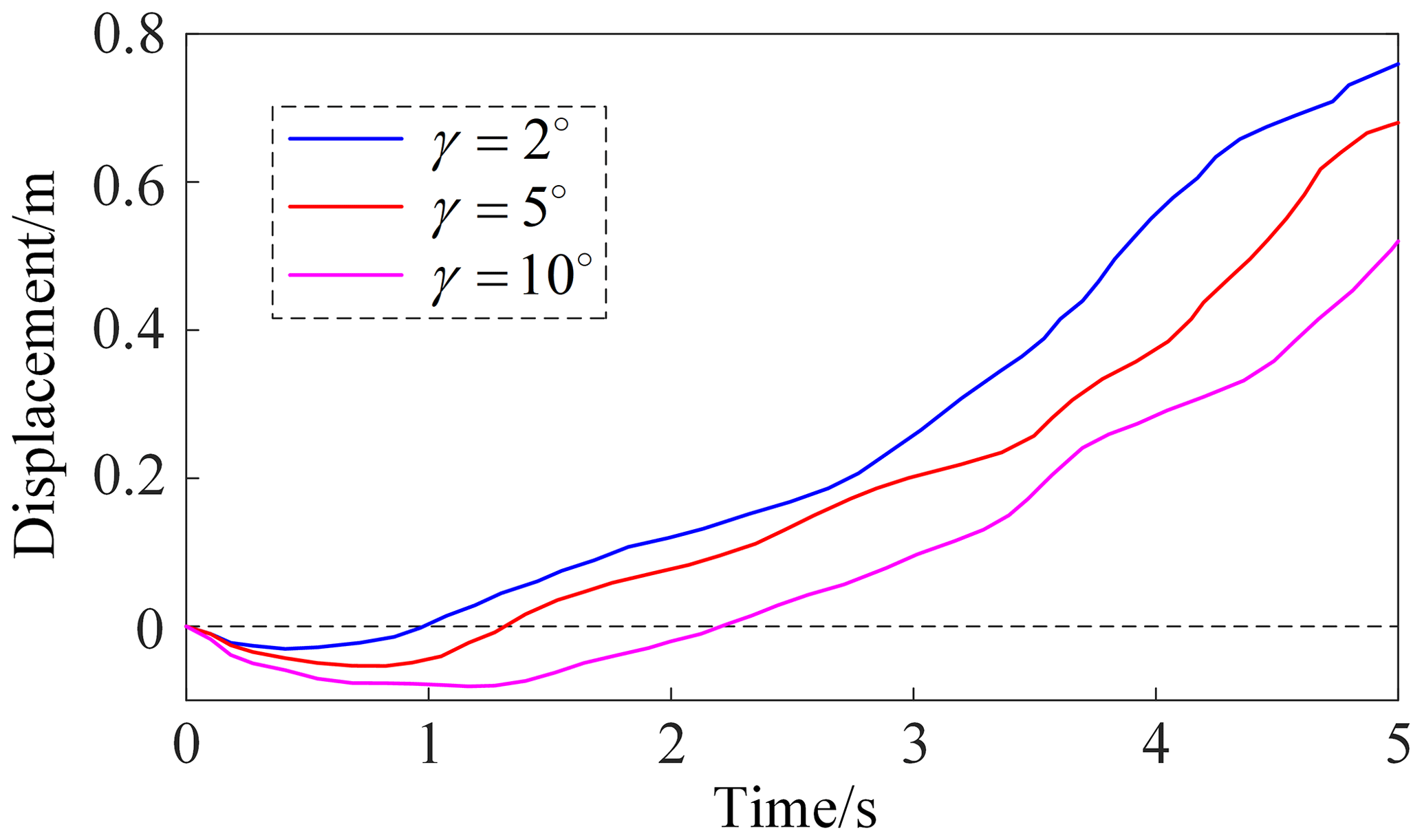
When the slope angle is γ=2°, the wheeled rolling robot rolls a small distance along the negative direction of the X axis at the beginning. With the increase in power, the robot starts to climb straightly at 0.5 s and the maximum displacement reaches 0.76 m. When the slope angle is γ=5°, the wheeled rolling robot rolls along the negative direction of the X axis at the beginning. As the output torque increases, the robot starts to climb at 0.8s and finally completes the displacement of 0.67 m. Compared with the motion when the slope angle is γ=2°, the time for the robot to start climbing is delayed and the displacement is reduced. When the slope angle is γ=10°, the wheeled rolling robot begins to climb at 1.3 s and the displacement along the X axis direction is the only 0.5 m. It is worth noting that this is only for the initial conditions of the slope friction coefficient of 0.6 and the initial speed of 0.8 m s−1. If the input of the eccentric torque is increased or the friction coefficient of the slope is reduced, the climbing ability of the robot will be further improved.
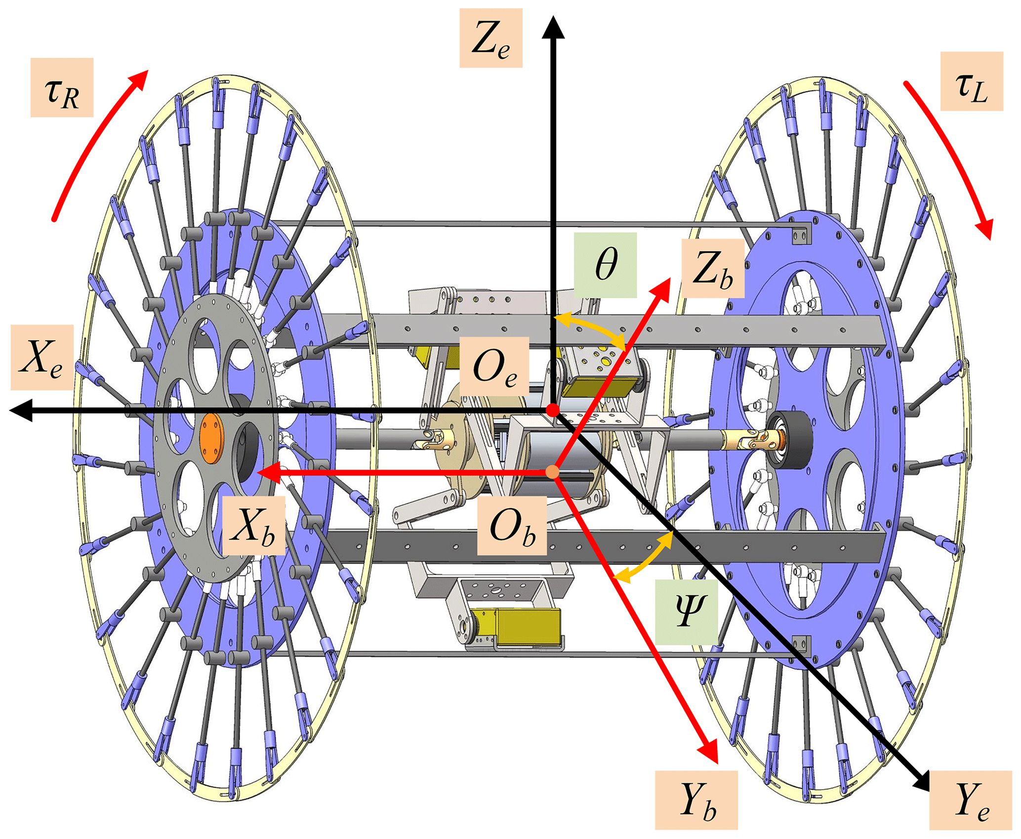
Since the wheeled rolling robot is subject to nonholonomic constraints, its dynamic model is a nonlinear system with strong coupling and many variables. Therefore, based on the nonholonomic dynamic Routh equation in generalized coordinates and using the Euler–Lagrange formula method, the dynamic model of the robot is established. Under the premise of only considering the linear rolling of the robot, the follow-up coordinate system, Ob, and the ground coordinate system, Oe, are defined as shown in Fig. 16. Under the conditions of pure rolling and no sideslip, the nonholonomic constraint of the robot is
where ψ is the angle between Yb and Ye, Dm is the center distance between the left and right wheels, and ψR and ψL are the angular displacements of the right and left wheels, respectively. According to the Lagrange formula and the Routh equation under generalized coordinates, the following applies:
In addition, Q is the generalized force and generalized torque acting on the robot:
Substituting Eq. (31) into Eq. (30) can obtain:
where . This can be obtained by the following:
The kinetic energy of the robot system is composed of the kinetic energy of the variable-diameter wheel train, the kinetic energy of the frame and the kinetic energy of the center-of-gravity adjustment device. Therefore, the kinetic energy of the whole robot system is expressed as
LC is the distance between the center of gravity and the axis of the two wheels. The height of the wheel shaft is defined as the zero-potential-energy point, and the potential energy of the robot system is
Because the Lagrange function is , the nonholonomic constraint relation of Eq. (29) can be expressed as follows:
The partial derivation of each variable in Eq. (30) is obtained separately, and the robot system dynamics equation is summarized as follows:
In Eq. (37), A(q) is the symmetric matrix, is the Coriolis force gravity term, τ is the output vector, E(q) is the output vector transformation matrix, F(q) is the constraint matrix, and λ is the Lagrange multiplier, whereas A(q), and F(q) are
Substituting Eq. (36) into Eq. (37) and multiplying ST(q) on both sides of the equation gives
We define y1=(x y ψ θ)T and , and then obtain
Based on the above equations, the nonlinear system dynamics model of the wheeled rolling robot is
Finally, the equation of the velocity and the angular acceleration of the left and right wheels is as follows:
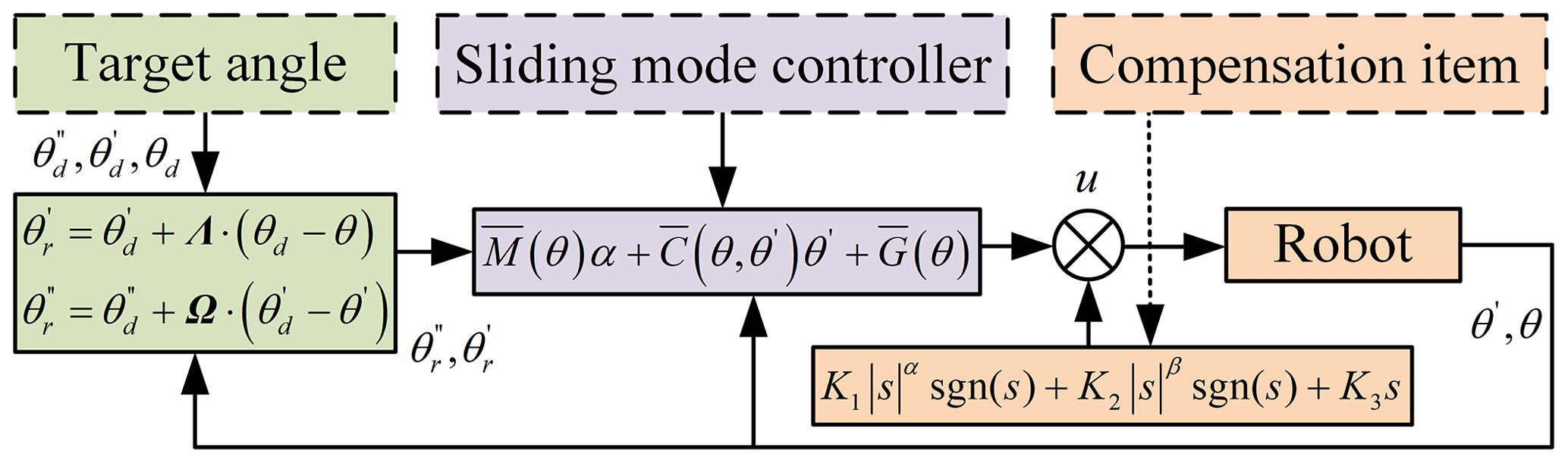
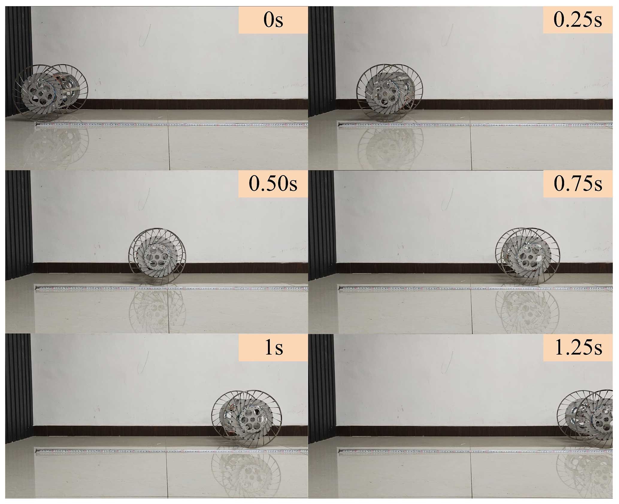
During the experiment, the lithium battery is used to power the steering gear of the wheeled rolling robot, and the control module of the robot includes a single-chip microcomputer and an inertial measurement unit (IMU). Most of the components of the wheeled rolling robot are aluminum alloy processing parts, and the lithium battery and the single-chip microcomputer are fixed on the moving platform of the 3-RRR parallel center of gravity adjustment device. Compared with the traditional PD controller, the sliding mode controller has stronger robustness in the face of external interference. Considering the problems of jitter and slow speed in the convergence process of the sliding mode reaching rate, a sliding mode controller based on the double exponential reaching law is designed for wheeled rolling robot, as shown in Fig. 17. It is worth noting that the control strategy is currently only applicable to the robot's linear rolling on the horizontal ground. As shown in Fig. 18, the wheeled rolling robot was placed on the smooth ground, with a friction coefficient of about 0.3 for the linear rolling test. The initial wheel diameter of the left and right wheels were both 380 mm, and the robot rolled forward under the eccentric torque conditions generated by the center-of-gravity adjustment device. The experimental results showed that the maximum linear rolling speed of the robot can reach 1.05 m s−1.
As shown in Fig. 19a and b, the wheeled rolling robot began to move out of stillness, and then the plane-turning experiment was carried out after the movement was smooth. During the turning process, the left-wheel diameter of the robot was 328 mm and the right-wheel diameter was 417 mm. Figure 19c was the path diagram of the silhouette synthesis of the robot's turning motion. After the experiment, the measured actual turning radius, RH, was about 1474 mm, which was different from the theoretical turning radius of 1593 mm. The error mainly comes from the deformation of the spoke by means of gravity and the slip phenomenon in the process of turning. In the process of changing from linear rolling the to turning motion, the wheel-diameter-switching effect of the robot variable-diameter wheel train is good, and the frame vibrates slightly, but it does not affect the dynamic stability of the robot as a whole.
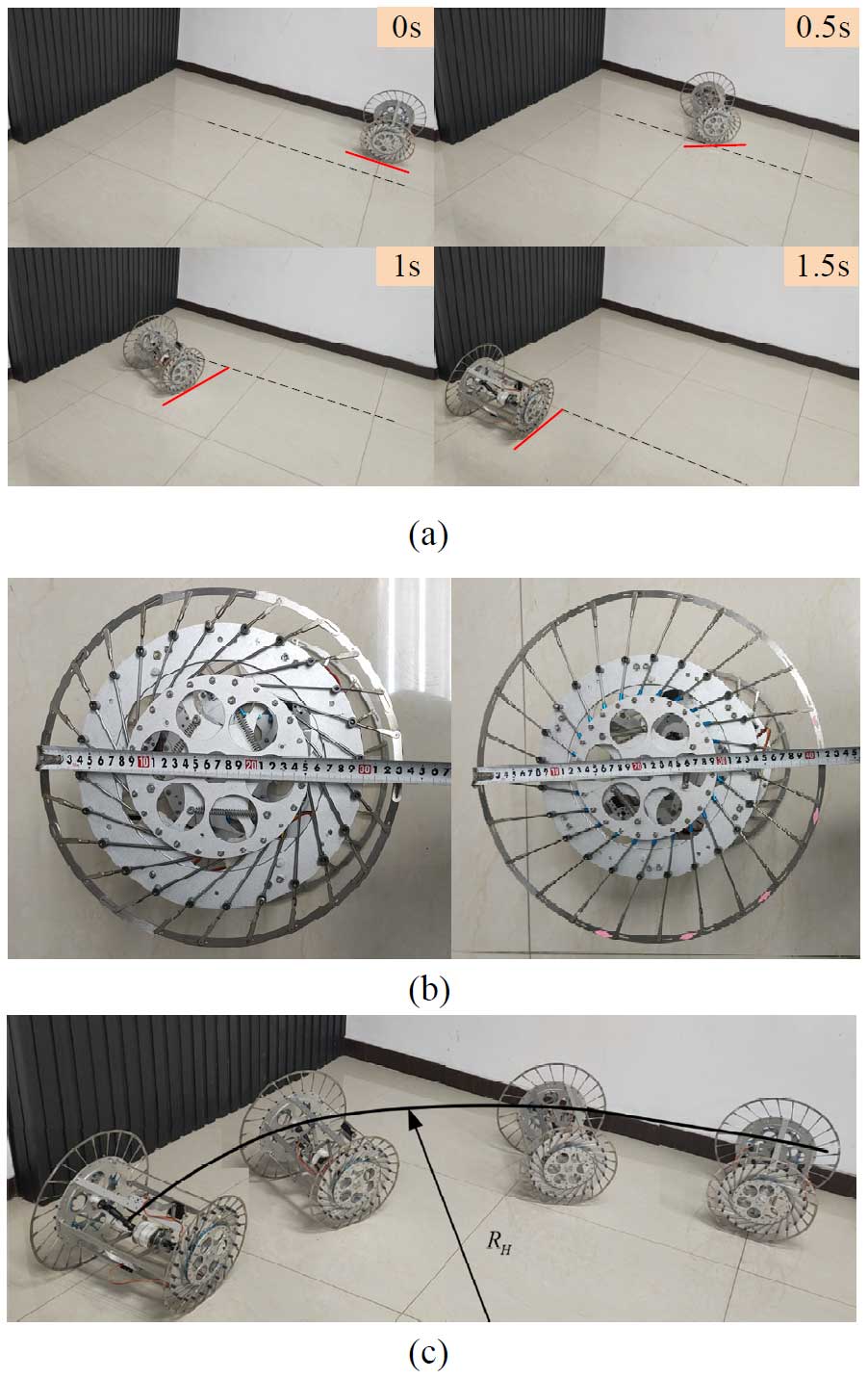
Figure 19(a) Turning motion experiment. (b) Diameter of left and right wheels. (c) Silhouette synthesis of turning motion.
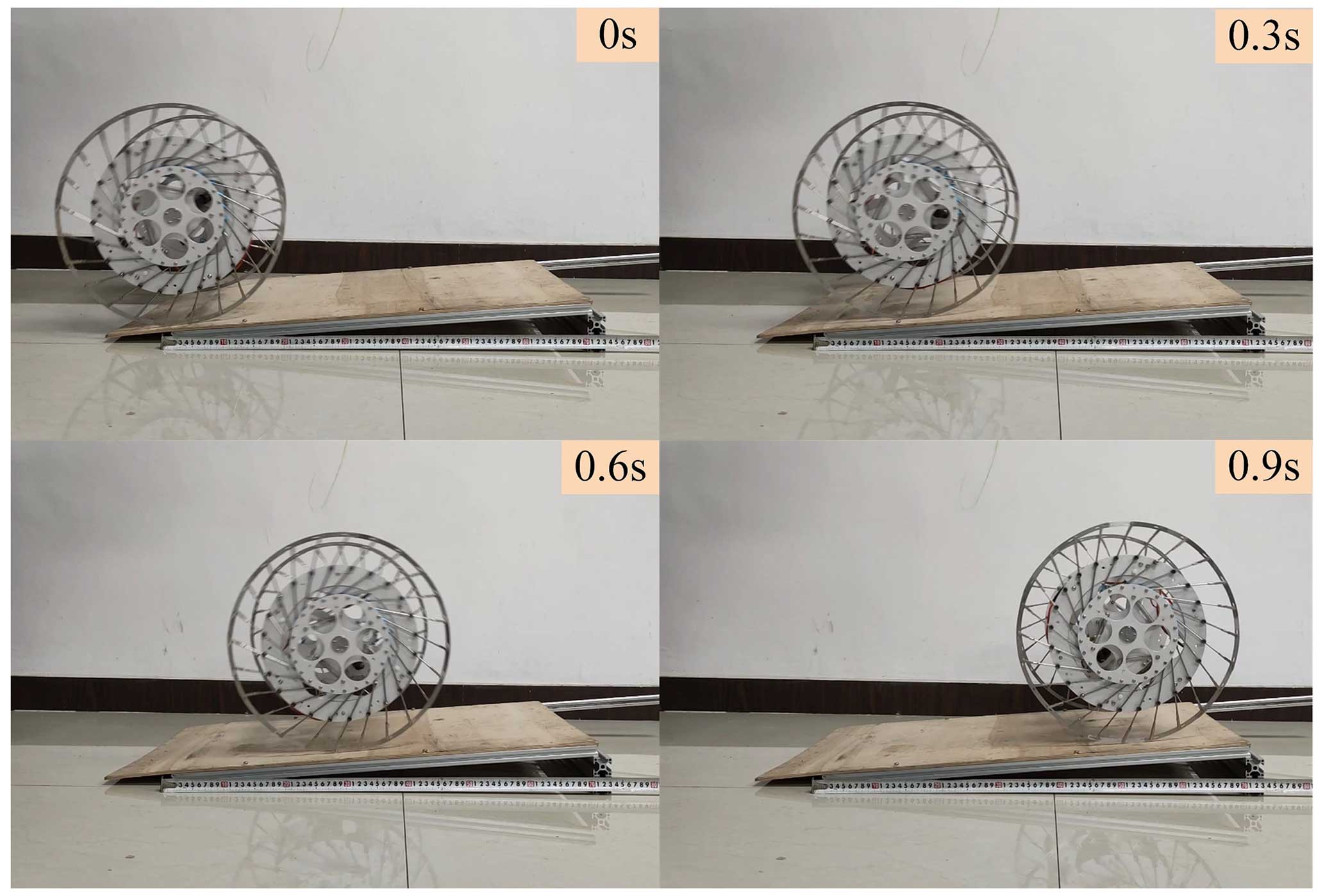
As shown in Fig. 20, the climbing motion experiment of the wheeled rolling robot was set on a dry wood surface with a friction coefficient of about 0.6, and the angle of the wooden slope is about 4.9°. The robot climbed at an initial speed of 0.6 m s−1. In the climbing process, the robot did not slip significantly and the arc sheet of the variable-diameter outer wheel did not have obvious extrusion deformation. Experiments showed that the robot can roll according to the preset route and has good stability when climbing at a small angle.
By comparing the structure and motion mode of various typical rolling robots, this paper designs a variable-diameter wheeled rolling robot. The wheeled rolling robot uses the planar 3-RRR parallel mechanism as the driving device and the spoke-type variable-diameter wheel as the adjusting device. The motion wheel controls the scaling of the spoke and then changes the size of the left- and right-wheel diameters of the robot. Since the edge of the variable-diameter outer wheel is composed of thin arc sheets and is in point contact with the ground, the wheeled rolling robot can achieve fast rolling with high motion efficiency and strong mobility by relying on a small driving force. Based on the eccentric torque optimization, and kinematic and dynamic analysis of the robot, a prototype is constructed to evaluate the motion ability of the robot, which successfully verifies the rationality of the robot design. Future research will be conducted from the following three perspectives: first, improving the motion control algorithm of the robot and realizing dynamic obstacle avoidance by path planning. The second is altering the material of the spoke-type variable-diameter wheel, reducing the weight while increasing the mass ratio and improving the mobility of the robot. The third is testing the robot's walking ability and obstacle-crossing ability on irregular pavement.
All the data used in this paper can be obtained upon request from the corresponding author.
HB provided design ideas and wrote the conclusion of the article. ZL has carried on the theoretical analysis to the robot and completed the first draft of the paper. ZL and CM built a prototype and carried out experimental verification.
The contact author has declared that none of the authors has any competing interests.
Publisher’s note: Copernicus Publications remains neutral with regard to jurisdictional claims made in the text, published maps, institutional affiliations, or any other geographical representation in this paper. While Copernicus Publications makes every effort to include appropriate place names, the final responsibility lies with the authors.
Thank you very much for your kind work and consideration during the publication of our paper. On behalf of the co-authors, we express our heartfelt thanks to the editors, the reviewers and the staff who helped the publication of the journal.
This research has been supported by the National Natural Science Foundation of China (grant no. 51305380).
This paper was edited by Engin Tanık and reviewed by four anonymous referees.
Bai, Y., Svinin, M., and Yamamoto, M.: Dynamics-Based Motion Planning for a Pendulum-Actuated Spherical Rolling Robot, Regul. Chaotic Dyn., 23, 372–388, https://doi.org/10.1134/s1560354718040020, 2018.
Belzile, B. and St-Onge, D.: ARIES: Cylindrical Pendulum Actuated Explorer Sphere, IEEE-Asme Trans. Mechatron., 27, 2142–2150, https://doi.org/10.1109/tmech.2022.3175989, 2022.
Cheng, J. L., Ma, P. Y., Ruan, Q., Li, Y. Z., and Zhang, Q. Q.: Design and motion analysis of double quadrilateral mobile mechanism, Ind. Robot., 49, 1256–1269, https://doi.org/10.1108/ir-12-2021-0290, 2022.
DeJong, B. P., Karadogan, E., Yelamarthi, K., and Hasbany, J.: Design and Analysis of a Four-Pendulum Omnidirectional Spherical Robot, J. Intell. Robot. Syst., 86, 3–15, https://doi.org/10.1007/s10846-016-0414-4, 2017.
Ding, W., Wu, J. X., and Yao, Y. A.: Three-dimensional Construction and Omni-directional Rolling Analysis of a Novel Frame-like Lattice Modular Robot, Chin. J. Mech. Eng., 28, 691–701, https://doi.org/10.3901/cjme.2015.0316.059, 2015.
Hao, Y. L., Tian, Y. B., Wu, J. X., Li, Y. Z., and Yao, Y. A.: Design and locomotion analysis of two kinds of rolling expandable mobile linkages with a single degree of freedom, Front. Mech. Eng., 15, 365–373, https://doi.org/10.1007/s11465-020-0585-3, 2020.
Ho, T. and Lee, S.: Development of a Minimally Actuated Jumping-Rolling Robot, Int. J. Adv. Robot. Syst., 12, 9, https://doi.org/10.5772/60495, 2015.
Hu, Y. B., Wei, Y. D., and Liu, M. N.: Design and Performance Evaluation of a Spherical Robot Assisted by High-Speed Rotating Flywheels for Self-Stabilization and Obstacle Surmounting, J. Mech. Robot., 13, 14, https://doi.org/10.1115/1.4050623, 2021.
Karavaev, Y. L. and Kilin, A. A.: The dynamics and control of a spherical robot with an internal omniwheel platform, Regul. Chaotic Dyn., 20, 134–152, https://doi.org/10.1134/s1560354715020033, 2015.
Kim, K., Agogino, A. K., and Agogino, A. M.: Rolling Locomotion of Cable-Driven Soft Spherical Tensegrity Robots, Soft Robot., 7, 346–361, https://doi.org/10.1089/soro.2019.0056, 2020.
Li, W. B., Zhang, W. M., Gao, Q. H., Guo, Q. W., Wu, S., Zou, H. X., Peng, Z. K., and Meng, G.: Electrically Activated Soft Robots: Speed Up by Rolling, Soft Robot., 8, 611–624, https://doi.org/10.1089/soro.2020.0012, 2021.
Li, Y. S., Yang, M. M., Wei, B., and Zhang, Y.: Energy-saving control of rolling speed for spherical robot based on regenerative damping, Nonlinear Dyn., 16, 111, 7235–7250, https://doi.org/10.1007/s11071-023-08233-z, 2023.
Li, Y. Z., Yao, Y. A., Cheng, J. L., Tian, Y. B., and Liu, R.: An agile assistant robot integrating operation and rolling locomotion, Ind. Robot., 44, 114–126, https://doi.org/10.1108/ir-05-2016-0147, 2017.
Liu, R., Yao, Y. A., and Li, Y. Z.: Design and analysis of a deployable tetrahedron-based mobile robot constructed by Sarrus linkages, Mech. Mach. Theory, 152, 22, https://doi.org/10.1016/j.mechmachtheory.2020.103964, 2020a.
Liu, X. Y., Zhang, C. Y., Ni, C., and Lu, C. H.: A reconfigurable multi-mode walking-rolling robot based on motor time-sharing control, Ind. Robot., 47, 293–311, https://doi.org/10.1108/ir-05-2019-0106, 2020b.
Mansour, N. A., Jang, T., Baek, H., Shin, B., Ryu, B., and Kim, Y.: Compliant closed-chain rolling robot using modular unidirectional SMA actuators, Sens. Actuator A-Phys., 310, 10, https://doi.org/10.1016/j.sna.2020.112024, 2020.
Mao, Z. B., Asai, Y., Yamanoi, A., Seki, Y., Wiranata, A., and Minaminosono, A.: Fluidic rolling robot using voltage-driven oscillating liquid, Smart Mater. Struct., 31, 10, https://doi.org/10.1088/1361-665X/ac895a, 2022.
Misu, K., Yoshii, A., and Mochiyama, H.: A Compact Wheeled Robot That Can Jump while Rolling, 25th IEEE/RSJ International Conference on Intelligent Robots and Systems (IROS), Madrid, SPAIN, 01–05 October, WOS:000458872706119, 7507–7512, 2018.
Miura, T., Hatakeyama, S., Iwase, M., and IEEE: Development of Wheel-Spider-Inspired Hexapod Robot Realizing Walking and Rolling Locomotion, 7th IEEE International Conference on Control, Mechatronics and Automation(ICCMA), Delft Univ Technol, Delft, NETHERLANDS, 06–08 November WOS:000543726100030, 174-178, 2019.
Phipps, C. C., Shores, B. E., and Minor, M. A.: Design and Quasi-Static Locomotion Analysis of the Rolling Disk Biped Hybrid Robot, IEEE Trans. Robot., 24, 1302–1314, https://doi.org/10.1109/tro.2008.2007936, 2008.
Ping, A., Zhang, C. Y., and Yang, J.: Design and kinematic analysis of new multi-mode mobile parallel mechanism with deployable platform, Ind. Robot., 49, 885–902, https://doi.org/10.1108/ir-09-2021-0216, 2022.
Sabet, S., Poursina, M., Nikravesh, P. E., Reverdy, P., and Agha-Mohammadi, A. A.: Dynamic Modeling, Energy Analysis, and Path Planning of Spherical Robots on Uneven Terrains, IEEE Robot. Autom. Lett., 5, 6049–6056, https://doi.org/10.1109/lra.2020.3010489, 2020.
Sagsoz, I. H. and Eray, T.: Design and Kinematics of Mechanically Coupled Two Identical Spherical Robots, J. Intell. Robot. Syst., 108, 20, https://doi.org/10.1007/s10846-023-01853-y, 2023.
Sastra, J., Chitta, S., and Yim, M.: Dynamic Rolling for a Modular Loop Robot, Int. J. Robot. Res., 28, 758–773, https://doi.org/10.1177/0278364908099463, 2009.
Shen, H. K., Zhang, K. H., and Nejati, A.: Research on Rolling Parallel Robot With Hydraulic Driven Antiparallelogram Chain, J. Mech. Robot., 9, 9, https://doi.org/10.1115/1.4035543, 2017.
Si, G. N., Chen, F. H., and Zhang, X. P.: Comparison of the Dynamic Performance of Planar 3-DOF Parallel Manipulators, Machines, 10, 23, https://doi.org/10.3390/machines10040233, 2022.
Tafrishi, S. A., Svinin, M., Esmaeilzadeh, E., and Yamamoto, M.: Design, Modeling, and Motion Analysis of a Novel Fluid Actuated Spherical Rolling Robot, J. Mech. Robot., 11, 10, https://doi.org/10.1115/1.4043689, 2019.
Tian, Y. and Yao, Y. A.: Dynamic rolling analysis of triangular-bipyramid robot, Robotica, 33, 884–897, https://doi.org/10.1017/s0263574714000666, 2015.
Tian, Y. B., Kong, X. W., Xu, K., and Ding, X. L.: Multi-Loop Rover: A Kind of Modular Rolling Robot Constructed by Multi-Loop Linkages, J. Mech. Robot., 13, 13, https://doi.org/10.1115/1.4048225, 2021.
Wang, X. L., Jin, H. Z., Zhu, Y. H., Chen, B. X., Bie, D. Y., Zhang, Y., and Zhao, J.: Serpenoid polygonal rolling for chain-type modular robots: A study of modeling, pattern switching and application, Robot. Comput.-Integr. Manuf., 39, 56–67, https://doi.org/10.1016/j.rcim.2015.12.003, 2016.
Wang, Y. J., Wu, C. L., Yu, L. Q., and Mei, Y. Y.: Dynamics of a rolling robot of closed five-arc-shaped-bar linkage, Mech. Mach. Theory, 121, 75–91, https://doi.org/10.1016/j.mechmachtheory.2017.10.010, 2018.
Wang, Z. R., Li, Y. Z., Su, B., Jiang, L., Zhao, Z. M., and Yao, Y. A.: Design and locomotion analysis of the tetrahedral mobile robot with only revolute joints (TMRR), Ind. Robot., 48, 614–625, https://doi.org/10.1108/ir-10-2020-0216, 2021.
Wei, X. Z., Tian, Y. B., and Wen, S. S.: Design and locomotion analysis of a novel modular rolling robot, Mech. Mach. Theory, 133, 23–43, https://doi.org/10.1016/j.mechmachtheory.2018.11.004, 2019.
Wu, H. S., Li, B. Y., Wang, F. T., Luo, B., Jiao, Z. W., Yu, Y., and Wang, P. F.: Design and Analysis of the Rolling and Jumping Compound Motion Robot, Appl. Sci.-Basel, 11, 17, https://doi.org/10.3390/app112210667, 2021.
Wu, J., Wang, J. S., Wang, L. P., and You, Z.: Performance comparison of three planar 3-DOF parallel manipulators with 4-RRR, 3-RRR and 2-RRR structures, Mechatronics, 20, 510–517, https://doi.org/10.1016/j.mechatronics.2010.04.012, 2010.
Wu, J., Gao, Y., Zhang, B. B., and Wang, L. P.: Workspace and dynamic performance evaluation of the parallel manipulators in a spray-painting equipment, Robot. Comput.-Integr. Manuf., 44, 199–207, https://doi.org/10.1016/j.rcim.2016.09.002, 2017.
Wu, J., Yu, G., Gao, Y., and Wang, L. P.: Mechatronics modeling and vibration analysis of a 2-DOF parallel manipulator in a 5-DOF hybrid machine tool, Mech. Mach. Theory, 121, 430–445, https://doi.org/10.1016/j.mechmachtheory.2017.10.023, 2018.
Zhang, Q. Q., Li, Y. H., Yao, Y. A., and Li, R. M.: Design and locomotivity analysis of a novel deformable two-wheel-like mobile mechanism, Ind. Robot., 47, 369–380, https://doi.org/10.1108/ir-09-2019-0183, 2020.
Zhang, X. C. and Zhang, X. M.: A comparative study of planar 3-RRR and 4-RRR mechanisms with joint clearances, Robot. Comput.-Integr. Manuf., 40, 24–33, https://doi.org/10.1016/j.rcim.2015.09.005, 2016.
- Abstract
- Introduction
- Design of wheeled rolling robot
- Kinematics analysis of the wheeled rolling robot
- Dynamics analysis of the wheeled rolling robot
- Prototype and experiment
- Conclusions
- Data availability
- Author contributions
- Competing interests
- Disclaimer
- Acknowledgements
- Financial support
- Review statement
- References