the Creative Commons Attribution 4.0 License.
the Creative Commons Attribution 4.0 License.
 | 03 May 2024
Study on cutting temperatures of SiCp ∕ Al composites for ultrasonic vibration-assisted cutting
Qingling Wu
Shuaijie Zhai
Yongsheng Du
Dong Yan
Yakun Yang
In order to deeply understand the cutting mechanism of SiCp Al in ultrasonic vibration-assisted turning, a prediction model of a cutting temperature field of SiCp Al composites in UVAC (ultrasonic vibration-assisted cutting) was established. A theoretical model of instantaneous cutting depth and transient shear angle was established considering the real-time changing cutting depth, tool front angle and shear angle characteristics of UVAC. The relationship between cutting speed, shear speed and chip flow speed in UVAC processes is revealed, as well as the shear force and the front cutter friction force. Finally, the influence of heat generated by the heat source zone and shear heat source zone on the temperature rise was calculated, and the temperature field model was established. The experiment of processing SiCp Al composites by UVAC was carried out. SiCp Al composites with 25 % volume fraction were turned, and the cutting temperature data were measured and recorded by an infrared thermal imaging device. The cutting speed, cutting depth and feed rate were tested by a single factor, and the changes in cutting temperature under different parameters were compared. Finally, the experimental data were compared with the theoretical values to verify the validity of the theoretical model.
- Article
(7699 KB) - Full-text XML
- BibTeX
- EndNote


In recent years, SiCp Al composite materials have been widely used in many fields due to a series of advantages such as high temperature resistance, fatigue resistance and a low thermal expansion coefficient (Pramanik, 2014; Liu et al., 2014; Wang et al., 2019). However, due to the high strength and hardness properties of the material itself, conventional methods cannot meet the requirements of high efficiency, high precision and high surface quality during processing.
Various studies have shown that ultrasonic vibration-assisted cutting (UVAC) technology can improve the cutting mechanism of SiCp Al composite materials. At the same time, the heat generated during the cutting process will have a significant impact on the formation of accumulated edges, the size of the cutting force, the particle fragmentation, the tool wear and service life as well as the performance and surface morphology of the processed material (J. Zhou et al., 2022; Lu et al., 2020). Zha et al. (2018) studied the material removal of SiCp Al-based composites in ultrasonic vibration-assisted scratching and traditional scratching experiments. The results indicate that the material removal rate of ultrasonic vibration-assisted scratching is higher than that of scratches formed by traditional methods. At the same time, ultrasonic vibration plays an important role in reducing the grinding force and friction coefficient and improving the surface morphology of machining. Zheng et al. (2018) found through experiments that the material removal behavior of SiCp Al composite materials at the macro scale is similar to that of metals and has a high material removal rate in ultrasonic vibration-assisted scratching technology. Meanwhile, SiC particles tend to maintain structural integrity rather than fracture or pull-out. Li et al. (2023) established kinematic and scratch force models to describe the scratch process of SiCp Al composites in their research on the influence of ultrasonic vibration on the subsurface of SiCp Al composites. Rotary ultrasonic vibration-assisted scratch testing was designed for high-volume fraction SiCp Al composite materials, with scratch trajectories including intermittent, continuous and semicontinuous ones. By observing the subsurface morphology, the subsurface damage under conventional scratches and rotary ultrasonic vibration-assisted scratches mainly includes particle cracking, matrix tearing and interface damage. The results indicate that ultrasonic vibration can effectively reduce the subsurface damage of SiCp Al composite materials. Y. Zhou et al. (2022) conducted conventional cutting and ultrasonic vibration-assisted cutting finite-element simulations on SiCp Al composite materials and studied the damage forms of SiC particles under different cutting paths. Finally, experimental verification was conducted. The results indicate that ultrasonic vibration-assisted cutting can reduce cutting force and surface roughness and improve the surface integrity of SiCp Al composite materials compared to conventional cutting while ensuring a reduction in subsurface damage. Zheng et al. (2021) also established a cutting model for SiCp Al composite materials using ABAQUS software. It was found that, when SiC particles were completely fractured and pulled out, the SiC particles and their surrounding matrix were severely damaged. At the same time, the comparison between the simulation and the experiment shows that SiCp Al can achieve better surface integrity during ultrasonic vibration-assisted cutting.
The heat generated during the cutting process of composite materials will have a relative impact on the cutting results, workpiece surface quality and tool wear. Although scholars at home and abroad have studied the cutting temperature of various materials, temperature research is still in its infancy (Longbottom and Lanham, 2006; Liu et al., 2023). Song et al. (2017) used self-lubricating tools and conventional tools, respectively, to study the cutting temperature and tool wear during AISI1045 hardened steel cutting using dry machining methods. The results indicate that self-lubricating tools exhibit excellent efficiency and stability in reducing cutting temperature, and tool wear is reduced compared to traditional self-lubricating tools. Saez-de-Buruag et al. (2018) believe that infrared thermal imaging technology is a reliable temperature measurement technology because it can achieve real-time monitoring of the tool temperature and thermal field. At the same time, research was conducted on four types of ferrite pearlite steels (16MnCr5, 27MnCr, C45 and C60). A new calibration method is proposed, where the calibration curve directly relates to the actual temperature and radiation temperature. The results indicate that this method is effective in determining the actual effects of the cutting speed and feed rate. In order to gain a deeper understanding of the changes in cutting temperature during the cutting process, Su et al. (2020) partitioned the heat sources during the cutting process and focused on studying the evolution laws of chip temperature, tool chip contact temperature and tool workpiece contact temperature. The results indicate that the variation of temperature with cutting speed varies at different measurement points. From the perspective of tool performance, the influence of chip shape and temperature changes on tool wear was discussed. Jamil et al. (2023) established a two-dimensional milling model of Ti-6Al-4V alloy using finite-element software to investigate whether the cutting temperature simulated by finite-element analysis can reasonably represent the actual situation. The influence of coolant on the cutting temperature was considered, and the cutting temperature was obtained. Finally, the experimental values were compared with the simulation results, and the maximum error was within 7 %. It is concluded that two-dimensional modeling is an effective tool for predicting milling temperature within a reasonable error range. Meng and Lin (2021) established a two-dimensional orthogonal cutting model and a finite-element model for the high-speed milling process of ADC12 aluminum alloy to analyze the impact of increasing cutting speed on cutting temperature and the changes in chip morphology. The results show that, as the cutting speed increases, the chip morphology changes from continuous to serrated and then returns to continuous. The cutting temperature also increases with the increase in cutting speed.
In summary, this article aims to study the cutting temperature of SiCp Al composite materials processed by UVAC, establish a cutting temperature prediction model and use the finite-element simulation analysis software ABAQUS to simulate the cutting process. Simulate the influence of different parameters on cutting temperature through finite-element simulation technology and verify the trend of cutting temperature changes through experiments. Study the changes in cutting temperature under different cutting parameters and vibration parameters, providing a reference for future research on the machining mechanism of composite materials.
2.1 Two-dimensional ultrasonic vibration-assisted cutting process analysis
On the basis of conventional cutting, two-dimensional ultrasonic vibration-assisted cutting technology is a special machining method, which uses an external excitation device to make the tool carry out high-frequency simple harmonic vibration along the cutting direction and the cutting depth direction, so that the tool tip presents a periodic elliptical motion trajectory. Due to its characteristics, it is considered one of the effective ways of improving the machining performance of difficult materials by most scholars. In the cutting process, driven by piezoelectric ceramics, the tool makes a periodic harmonic motion along the cutting direction (X direction) and vertical direction (Y direction), respectively. The motion trajectory of the tool tip can be expressed as
where t represents time; X(t) and Y(t), respectively, represent the absolute displacement along the cutting direction (X) and vertical direction (Y) during tool vibration; A1 and A2, respectively, represent the amplitude of the corresponding direction; and f and φ are the vibration frequency and phase difference, respectively.
Considering the cutting speed, the motion path of the tool relative to the workpiece is
By taking the derivative of time t, the instantaneous velocity of the tool in the cutting process can be obtained:
In order to realize intermittent separation and contact between the tool and workpiece in the two-dimensional ultrasonic vibration-assisted cutting process, the maximum instantaneous speed of the tool along the cutting speed direction should not be less than the cutting speed of the tool relative to the workpiece, i.e.,
According to the above formula, the motion speed of the tool tip in the UVAC cutting process can be obtained:
The resultant velocity forms an angle γ with respect to the horizontal axis, i.e., the included angle of the tool with respect to the workpiece (time-varying front angle), which is given by the following formula:
According to shear deformation theory, the relationship between the shear angle, friction angle and tool front angle can be obtained as follows:
In the UVAC process, it can be known from the cutting path that the included angle of the axial and radial velocities of the tool tip changes in each cutting cycle. Thus, the time-varying shear angle in the cutting process can be seen as follows:
where ϕ0 is the shear angle of the conventional cutting process. (In order to reduce the redundancy of the formula, part of the shear angle ϕ and tool front angle γ mentioned in the following section are time-varying.)
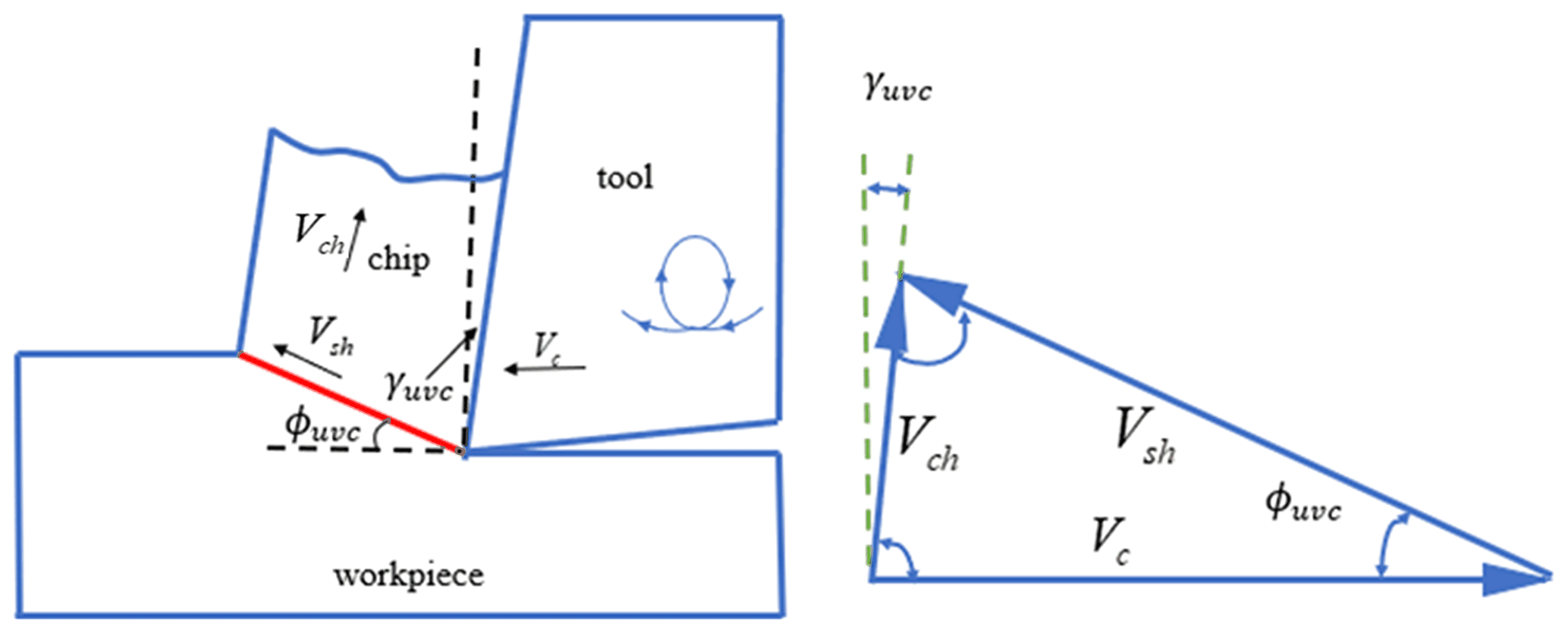
In addition to cutting speed Vc, two other speeds are involved in the cutting process: shear rate Vsh and chip outflow rate Vch.
Figure 1 shows the speed during UVAC cutting. The shear velocity Vsh and chip velocity Vch on the shear plane can be expressed as the cutting velocity Vc, where ϕuvc is the time-varying shear angle and γuvc is the time-varying tool front angle. The shear velocity and chip outflow velocity can be calculated as follows:
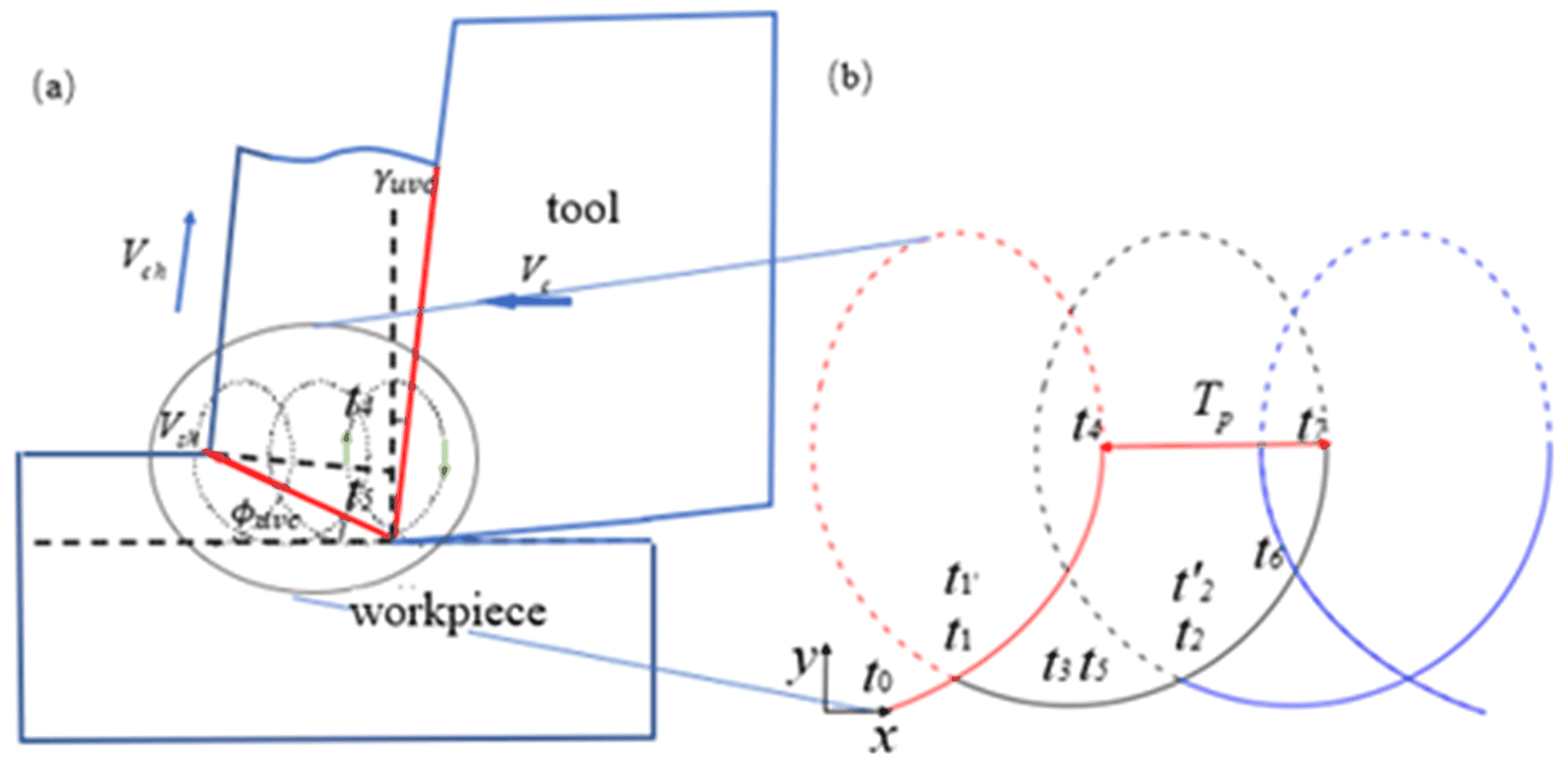
The invalid cutting time is the time it takes for the tool to not cut the workpiece during the UVAC process, as shown in Fig. 2b from t7 to t2. At this time, the cutting force is 0. When the tool comes into contact with the workpiece, from point t1 in Fig. 2b to t7 (black solid line interval), it is called the effective cutting time. At this point, UVAC technology does not change the cutting mechanism, and the cutting force is similar to ordinary cutting.
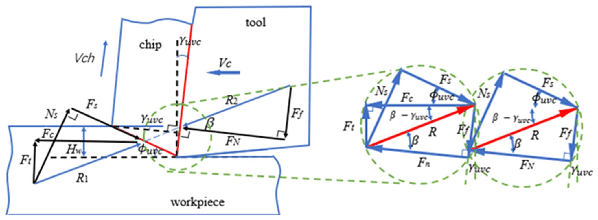
As shown in Fig. 3, the force acting on the tool–chip interface can be decomposed into two components: Ff, the frictional force opposite to chip motion, and Fn, where force R2 is the vector sum of these two forces. In addition, shear forces Fs and normal shear forces Ns also appear on the shear plane, and force R1 is the vector sum of these forces.
Due to the fact that the temperature of the workpiece being cut is higher than the temperature of the cutting plane and the deformation speed is faster, the shear stress and compressive stress on the surface of the cutting tool vary over time and can be obtained by the following formula:
where B is the effective cutting width and S is the hardness of the material.
Therefore, considering the time-varying uncut chip thickness caused by cutting characteristics, the shear force in the shear zone and the normal shear force can be obtained:
Also taking into account the force–balance relationship shown in Fig. 3, Ff and Fn can be expressed as the function γ of cutting force Fc, thrust Ft and tool front angle γ:
2.2 Ultrasonic vibration-assisted cutting SiCp Al composite cutting temperature analysis
Along with the machining process generated by the cutting heat in the whole process of metal cutting playing a decisive role, the workpiece is heated in the cutting heat, and the resulting cutting temperature under the action slightly softens. To a certain extent, the cutting provides favorable factors, but too high a temperature will also bring many adverse factors. The cutting temperature plays a large role in the formation of chip nodules; the size of the cutting force, tool wear and service life; and the surface morphology and properties of materials after machining.
The heat generated in UVAC processing is transferred to chips, workpieces, tools and cooling media. In addition, the UVAC's intermittent tool–chip contact mode increases the cooling time of the tool and chip in the air, which greatly promotes heat loss during cutting.
In ultrasonic vibration-assisted machining, the tool transmits ultrasonic vibration to the workpiece and changes the yield strength of the workpiece in the shear zone. Therefore, in order to evaluate the instantaneous influence of ultrasonic softening and machining parameters on the yield strength in the J–C model, ultrasonic softening factors were introduced:
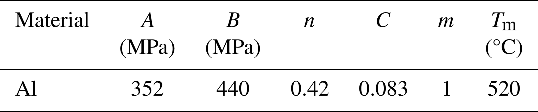
where , , εn, Tmt, Trm and Eu, respectively, represent the strain rate, reference strain rate, material shear strain, material melting temperature, reference temperature and ultrasonic energy. Some parameters are shown in Table 1. A, B, C, m and n, respectively, represent J–C model constants. Further considering the influence of machining parameters and shear angle, the improved J–C model Verma et al. (2018) can be expressed as
where ρ, c, k, Hw and Vc, respectively, represent material density, specific heat of the workpiece, heat conductivity, instantaneous cutting depth and cutting speed.
Table 1J–C constitutive model parameters of Al (Lu et al., 2014).
The equivalent plastic strain and equivalent plastic strain rate of the shear plane can be expressed as follows:
where COxley represents the constant of the Oxley model.
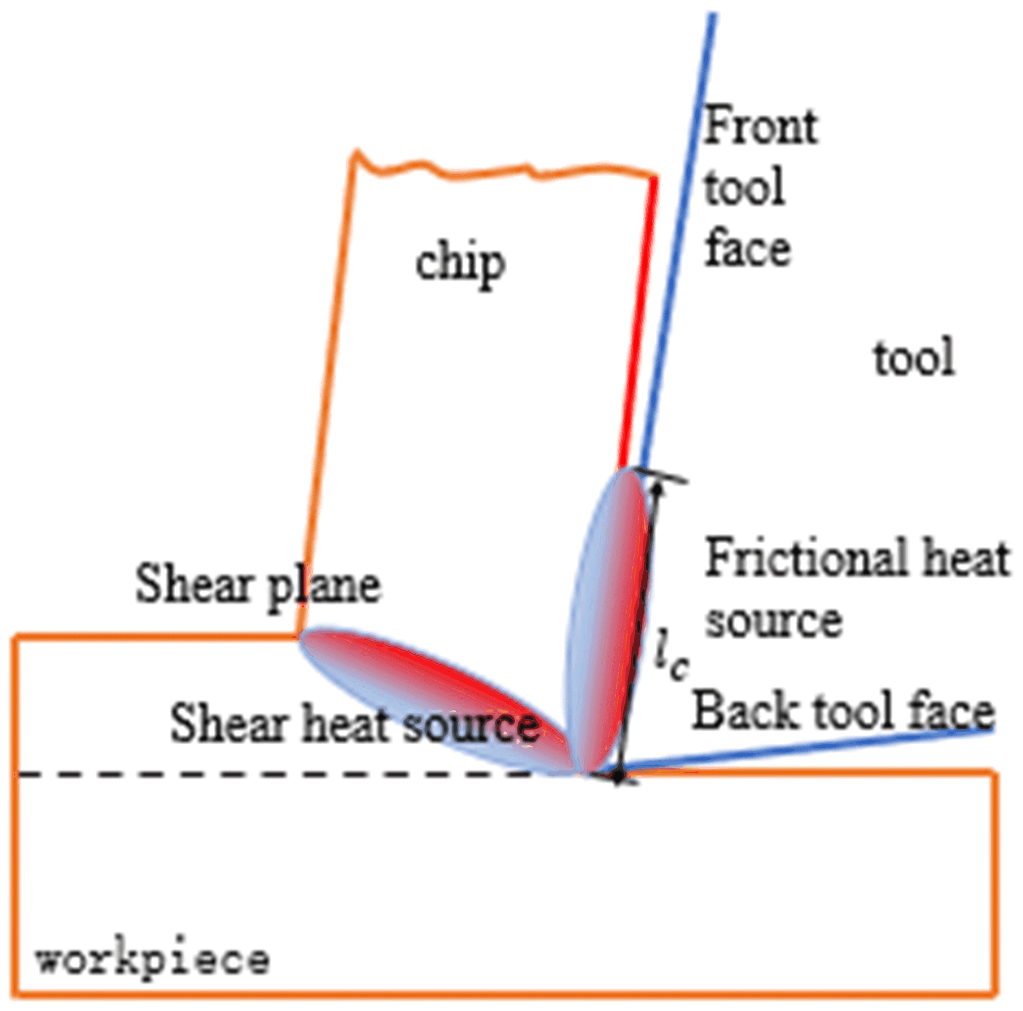
In the cutting process, heat generation mainly occurs in the main shear zone and the secondary shear zone, as shown in Fig. 4. If the tool is not very sharp, a third heat source is created due to friction between the tool and the new workpiece surface. The unit cutting depth is calculated in the primary shear heat source according to the following formula:
where Hw(t) is the instantaneous cutting depth.
According to the cutting heat generation formula (18), the average temperature rise during cutting in the first-stage shear zone can be calculated as follows:
where ρ, c and T0, respectively, represent the mass density, specific heat capacity and initial temperature of the workpiece. The heat transfer component is evaluated by a parameter representing the value transferred to the chip, defined as
where Rq is a calorific value, which can be defined as
where ζ is the thermal diffusion rate, which can be calculated as
where λ is the thermal conductivity coefficient.
Figure 5 is a stress distribution model proposed by the (a) Zorev stress distribution model and the (b) heat flux distribution. It can be seen that the frictional stress remains constant in approximately half of the bonding area (ls area) of the cutting edge closest to the cutting edge but gradually decreases when the chips come out of contact with the rake face and eventually become zero. The stress distribution equation on the tool chip contact length is similar to the heat flux distribution equation, so the cutting flux distribution can be described as a stress distribution.
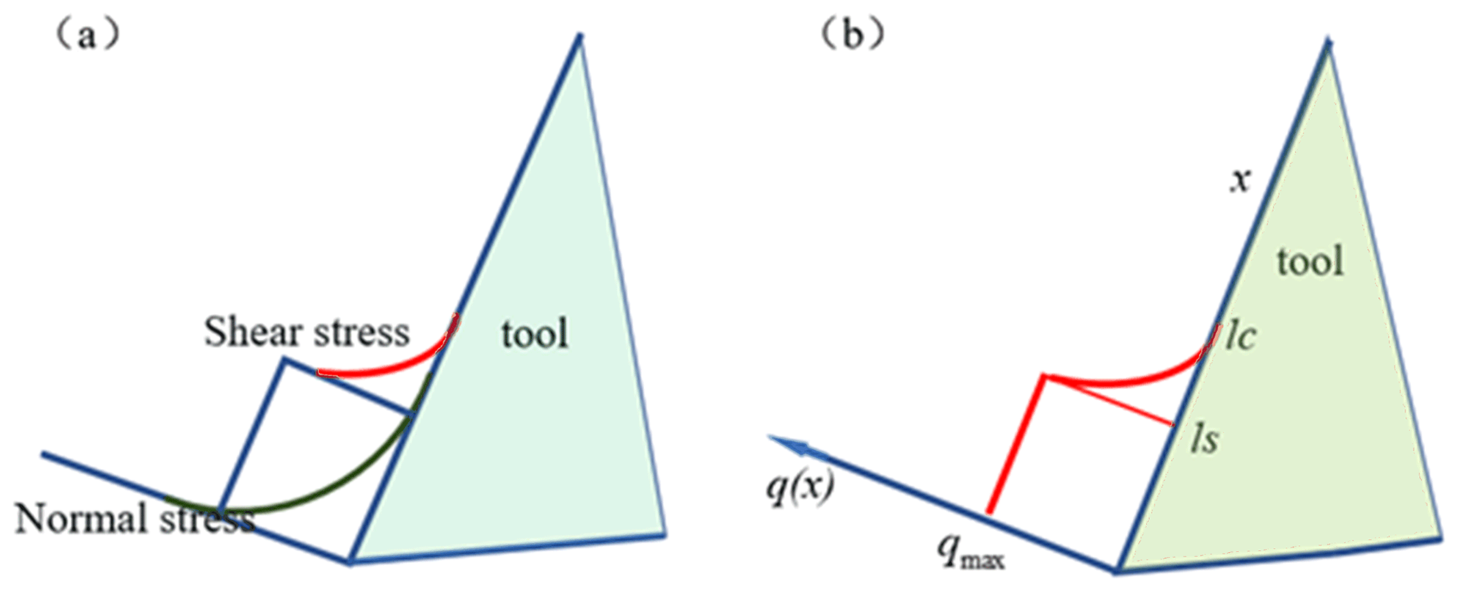
Figure 5Stress distribution model proposed by the (a) Zorev stress distribution model and (b) heat flux distribution (Teng and Wierzbicki, 2006).
The tool–chip contact interface is shown in Fig. 6. When the tool touches the workpiece, the tool–chip interface can be divided into an adhesive zone and a sliding zone. In the adhesive region, strong adhesion occurs in the interface due to the accumulation of cutting heat. In the sliding area, the adhesion is relatively weak due to the decrease in the cutting temperature. The total length of these two areas in lc of the interface is calculated as follows:
The process is assumed to have an orthogonal cutting geometry, with chips sliding on the front inclination plane (i.e., the secondary deformation zone) at a constant average friction coefficient. The heat generated by the unit cutting depth in the secondary zone is as follows:
Equation (23) is divided by the tool–chip contact length to obtain the heat flux:
Therefore, the cutting heat flux distribution function in the tool–chip contact interface is calculated as follows:
Unlike conventional cutting, the presence of tool–piece separation in the UVAC process makes it an intermittent cutting process. During the non-cutting duration, the tool surface will have heat convection with the cooling medium, such as air and fluid coolant. As the cutting process continues, this process will result in a reduction of heat, the value of which can be calculated by the heat convection equation:
where h is the convective heat transfer coefficient of the coolant.
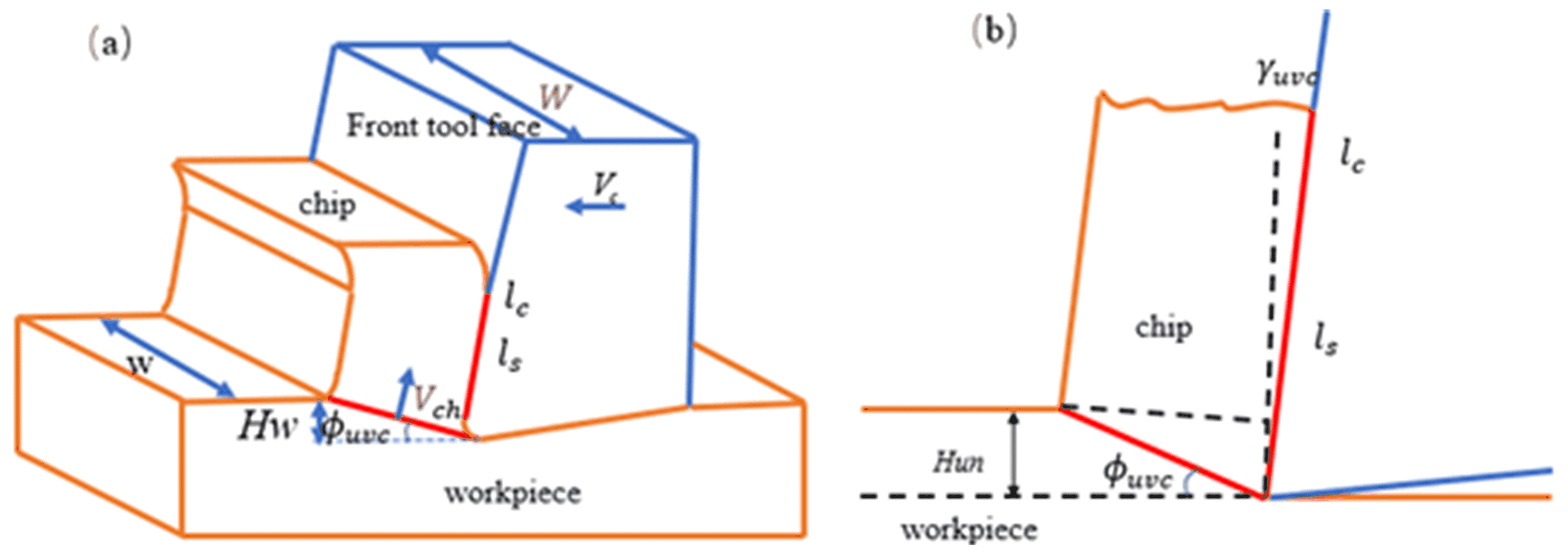
Figure 6Schematic diagram of the cutting process: (a) three-dimensional view; (b) intermediate cross-sectional view.
In Fig. 7, ds refers to the normal cross-sectional area of convective heat transfer, and its calculation formula on the front surface is as follows.
During the entire cutting process, although there is thermal convection between the rake face and the external environment, cutting heat is also transmitted through the tool during cutting. Therefore, this process can be simplified as a heat conduction system with two parallel walls. Conduction heat can be calculated in the following form:
where s is the thickness of the parallel wall. If the tool clearance angle α is zero, it is equal to the tool thickness. Otherwise, it can be calculated simply through geometric relations:
The composite cutting heat flux Q(t) on the front cutting surface, which is ultimately affected by the cutting temperature, is calculated as follows:
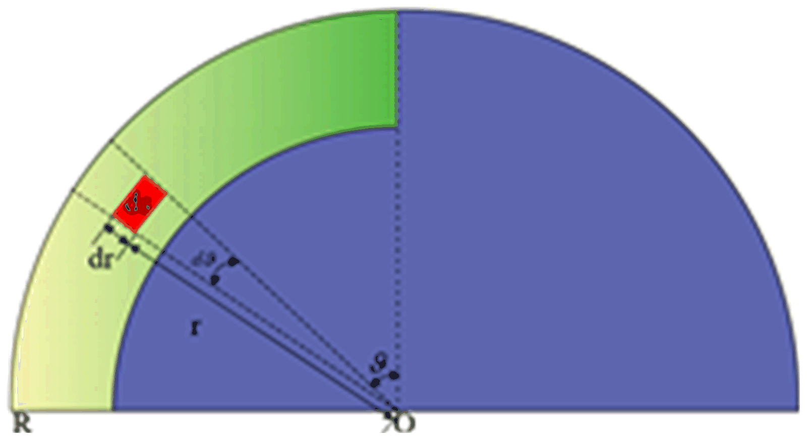
Figure 7Schematic diagram of the thermal convection cross-sectional area of the cutter surface before tool–chip contact.
2.3 Modeling of the cutting temperature
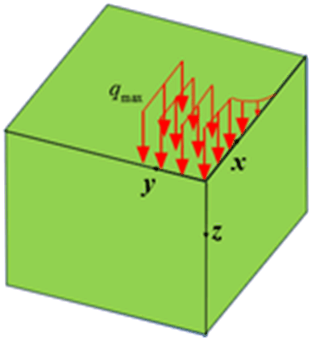
Based on thermodynamic definitions, heat sources can be modeled as semi-infinite rectangular angles in UVAC on the finite plane, as shown in Fig. 8. Then, the cutting temperature boundary condition is
To solve the above formula, the UVAC process is viewed as three mutually perpendicular transient planes of a semi-infinite semi-space, thus forming an eighth spatial corner point. Given a surface point at a certain time in space (x=xp, y=yp, z=0), the instantaneous heat source at time t can be calculated as
Therefore, according to Eqs. (26) and (29), the temperature solution of any surface point at a given time can be calculated by the following equation:
When time t is assumed, the average temperature of the tool front tool surface Tave can be calculated as the average of the surface integral:
3.1 Experimental equipment
The two-dimensional ultrasonic vibration auxiliary cutting device adopted in this paper is designed by the research group, and some parameters of the device are shown in Table 2 after testing.
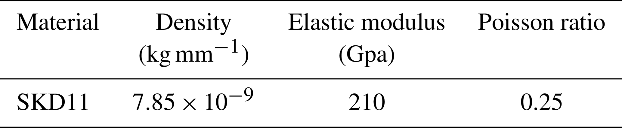
Because the frequency of the non-resonant device is low, in order to meet the vibration frequency requirements of ultrasonic vibration, this paper uses the ultrasonic vibration-assisted cutting device with unidirectional excitation. The amplitude is amplified by the horn and the direction of vibration is constantly changed, so that the tool obtains the micro displacement along the direction of cutting speed and the direction of cutting depth, respectively. Considering the stiffness, stability of the cutting device and simplification of the manufacturing process, the cylindrical straight beam at the end of the horn is made into an asymmetric structure to decompose the longitudinal vibration, as shown in Fig. 9b. The actual picture is shown in Fig. 9a, the device horn is made of die steel (SKD11), and the specific parameters are shown in Table 3.
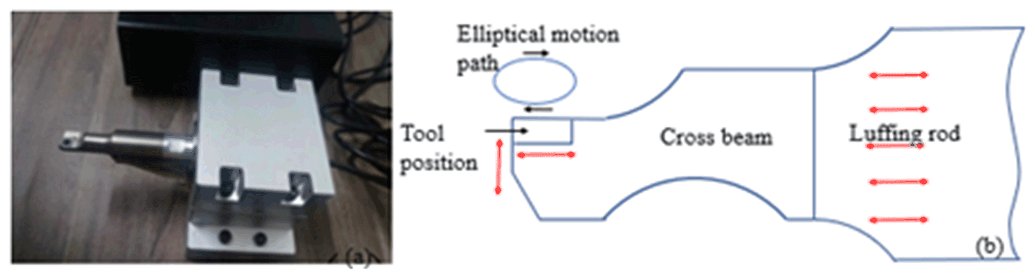
Figure 9Two-dimensional ultrasonic vibration system: (a) two-dimensional ultrasonic device; (b) schematic diagram of a two-dimensional ultrasonic device.
3.2 Experimental scheme design
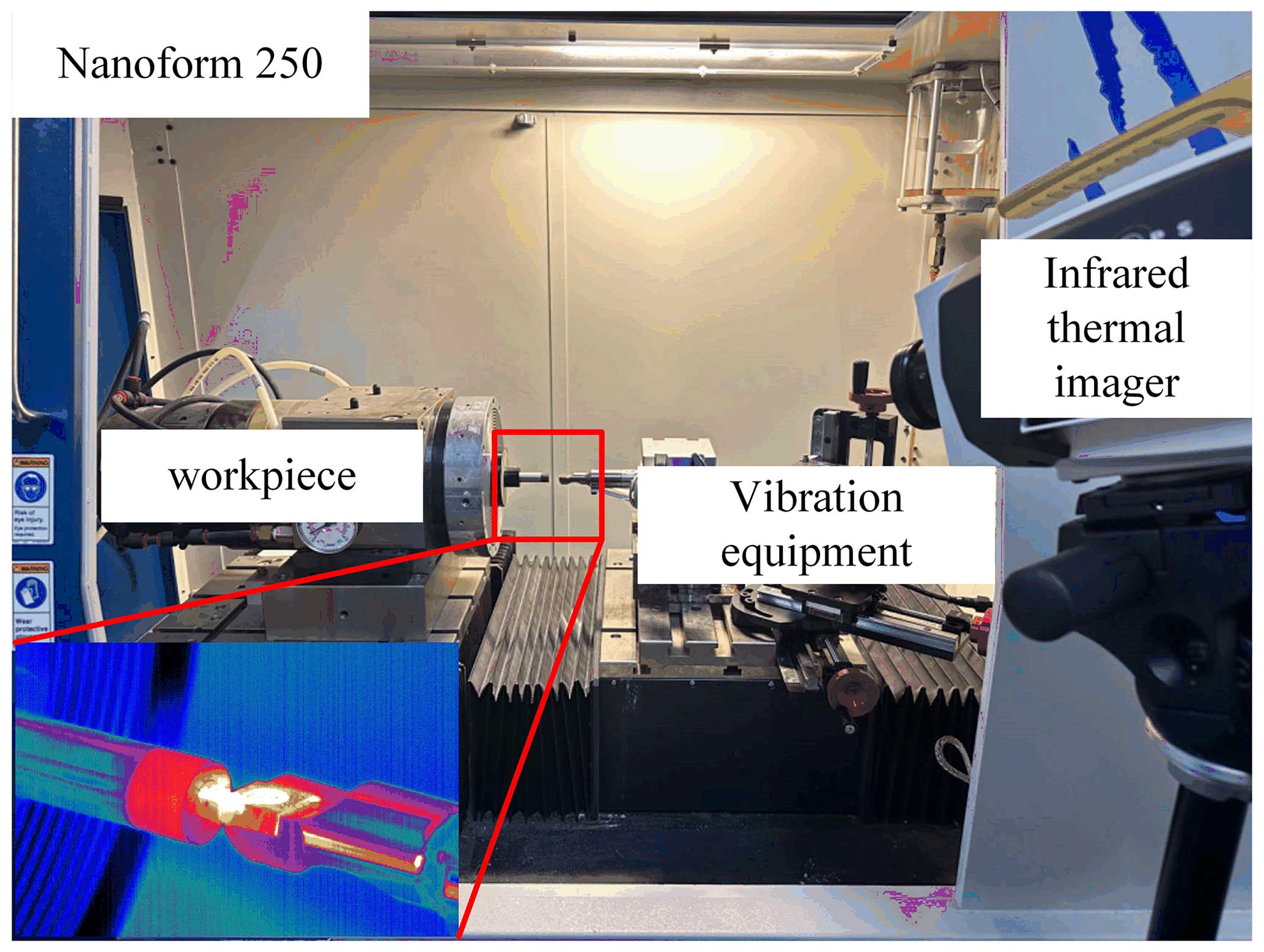
On the Nanoform250 ultra-precision machine tool, a customized fixture is used to fix the cutting device on the machine spindle and then to adjust the height. When the height adjustment is appropriate, adjust the thermal imaging device, and the experimental platform is shown in Fig. 10. The ultrasonic generator emits an electrical signal, which is ultimately converted into a micro displacement signal. Under the action of the amplitude converter, the tool is driven to vibrate axially and radially along the workpiece, forming an elliptical trajectory at the tool tip. During the cutting process, the cutting temperature information is collected through a thermal imager. Finally, the surface morphology of the workpiece was observed using a scanning electron microscope.
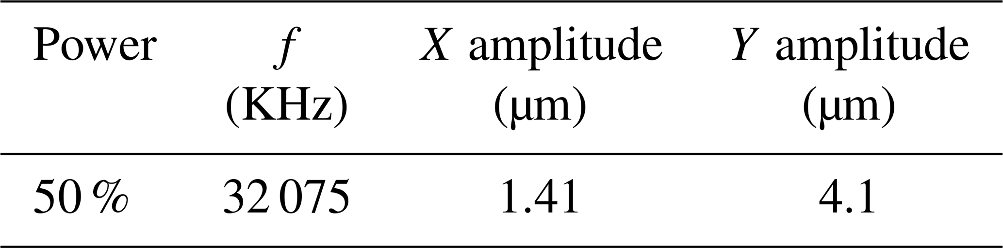
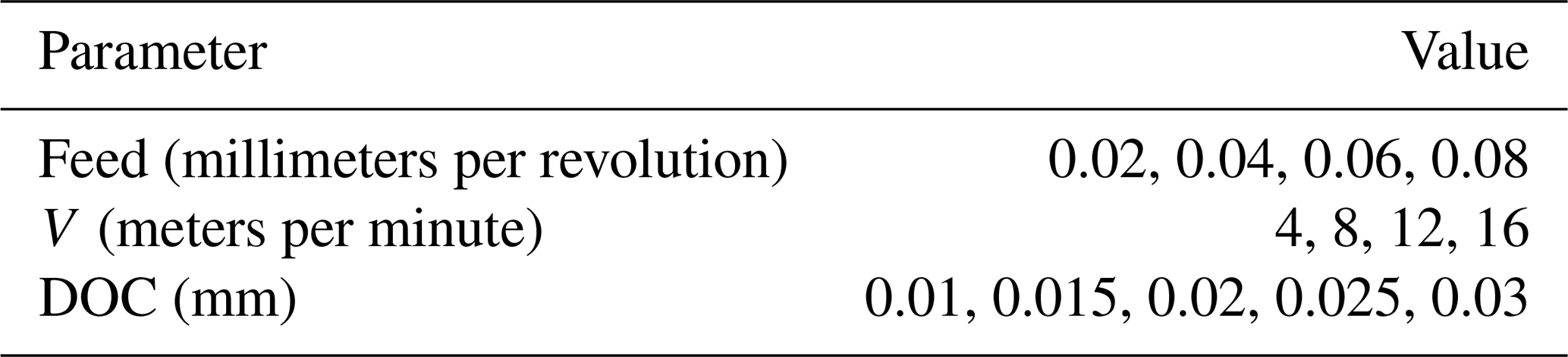
In the cutting experiment of this paper, the single-factor control variable experiment method is used; i.e., each group of experiments only changes a variable, and the other parameters are unchanged. In the cutting process, the power of the ultrasonic device used in this paper is always set to 50 %, and the tool X amplitude is 1.41 µm and the Y amplitude is 4.1 µm. Under such conditions, the specific experimental processing parameters are shown in Table 4.
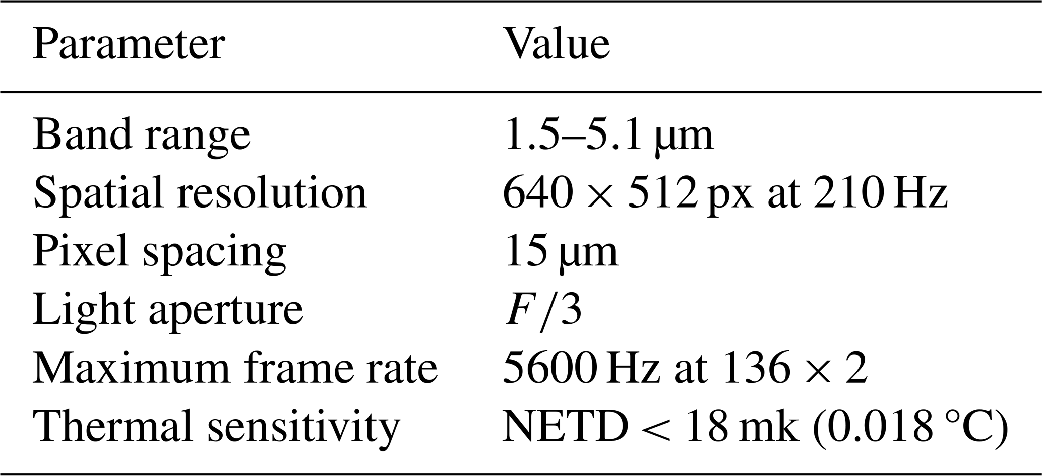
The tool-tip material used in this experiment is polycrystalline diamond, which is not applicable to the common thermocouple temperature measurement method. Therefore, in order to monitor the cutting temperature in real time, a TELOPS FAST M200 infrared thermal imaging device is used in this paper, as shown in Fig. 10. The device has the advantages of high sensitivity, stable imaging and a wide temperature measurement range. The technical parameters of the thermal imaging device are shown in Table 5.
3.3 Experimental results of the cutting temperature
3.3.1 Influence of the cutting speed on the cutting temperature
In order to study the effect of the cutting speed on the cutting temperature of SiCp Al composites, the single-factor experiment method of ultrasonic vibration end turning SiCp Al composites was adopted in this paper. The cutting speed was set as 4, 8, 12, and 16 m min−1, respectively, and the ultrasonic vibration frequency was 32 KHz. The X amplitude is 1.41 µm, the Y amplitude is 4.1 µm, the feed is 0.04 mm per revolution, and the cutting depth is 0.02 mm. The cutting temperature variation trend of SiCp Al composites at different cutting speeds was observed by the experiments. The relationship between the cutting temperature and the cutting speed is shown in Fig. 11.
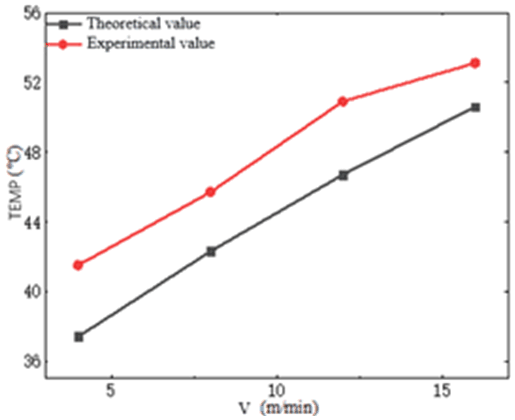
As shown in Fig. 11, under the same conditions, the cutting temperature increases as the cutting speed increases. When the cutting speed increases from 4 to 16 m min−1, the cutting temperature increases from 41.5 to 53.1 °C. Mainly because, in the turning process, increasing the cutting speed leads to the cutting layer of the cutting material per unit of time increases the consumption of power and also produces more chips, producing a lot of heat. When the cutting speed is 4 m min−1, the theoretical temperature is 37.4 °C, a 4.1 °C difference with the actual temperature, and the error is 9.88 %. When the cutting speed is 8 m min−1, the theoretical temperature is 42.3 °C, while the actual temperature is 45.7 °C, the difference is 3.4 °C, and the error is 7.44 %. When the cutting speed is 12 m min−1, the theoretical temperature is 46.7 °C, the actual temperature is 50.9 °C, the difference is 4.2 °C, and the error is 8.25 %. When the cutting speed is 16 m min−1, the theoretical temperature is 50.6 °C, the actual temperature is 53.1 °C, the difference is 2.5 °C, and the error is 4.71 %. The error is within 10 %. The reason for the error is that, when the cutting speed is increased, the impact force formed by the tool in contact with the workpiece is constantly intensified, which leads to the fracture of more particles, and the energy released is constantly enhanced, resulting in the gradual appearance of the error. At the same time, there will be a certain error when the cutting speed is converted to the spindle speed of the lathe during the machining process, and the tool wear and so on will have a certain impact.
3.3.2 Influence of the cutting depth on the cutting temperature
In order to study the effect of the cutting depth on the cutting temperature of SiCp Al composites, the single-factor experiment method of ultrasonic vibration end turning SiCp Al composites was adopted in this paper. The cutting depth was controlled as 0.010, 0.015, 0.020, 0.025, and 0.030 mm, respectively. The ultrasonic vibration frequency is 32 KHz, the X amplitude is 1.41 µm, the Y amplitude is 4.1 µm, the feed speed is 0.04 mm per revolution, the cutting speed is 8 m min−1, and the feed rate is 0.02 mm per revolution. At this time, the relationship between the cutting temperature and the cutting depth is shown in Fig. 12.
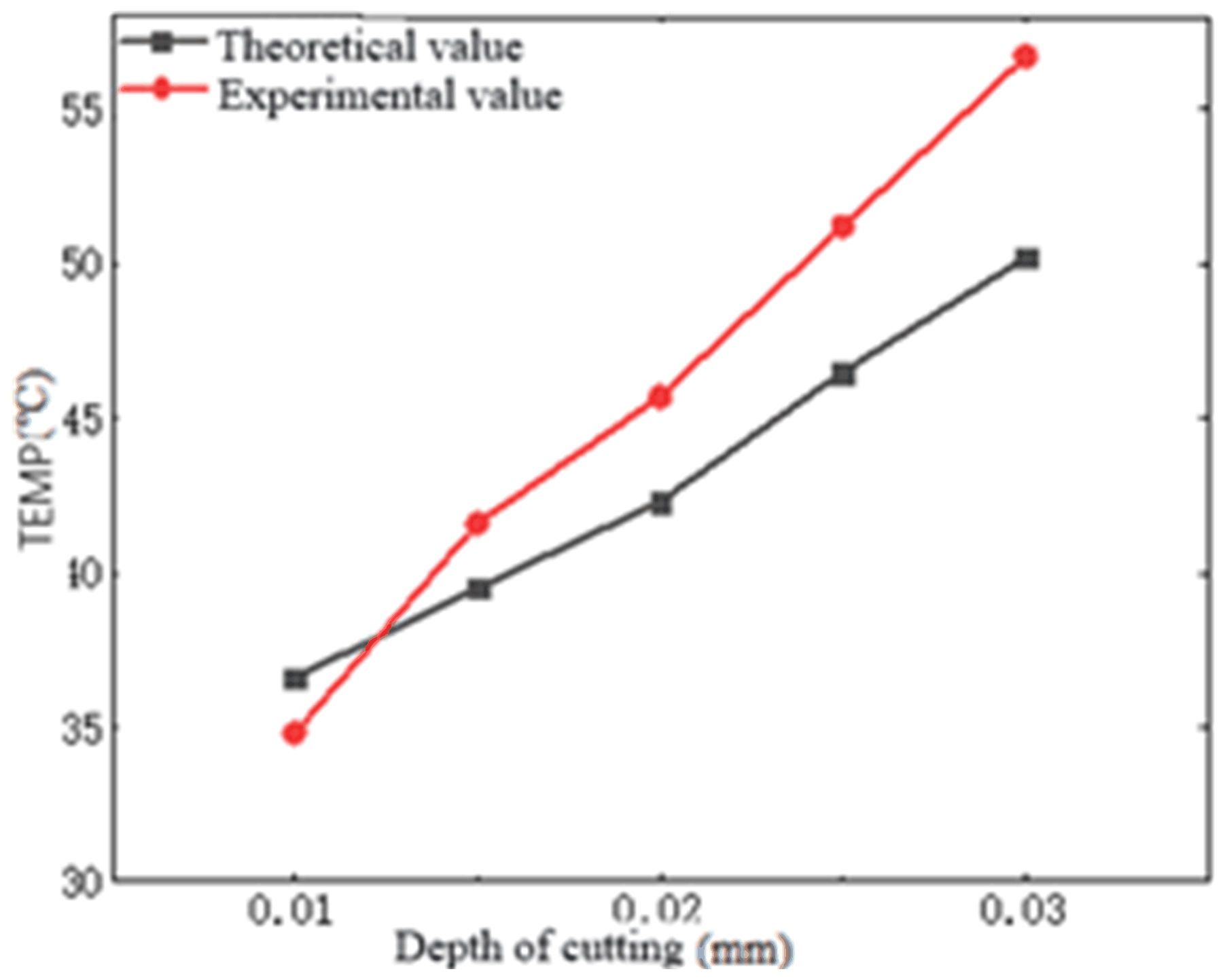
Figure 12Influence of different cutting depths on ultrasonic vibration-assisted cutting temperatures.
It can be seen from Fig. 12 that the changing trend of the ultrasonic vibration-assisted cutting temperature is consistent with the theoretical value. When the cutting depth becomes deeper, the cutting temperature of both the experimental and theoretical values increases. The essential reason is that, when the cutting depth increases, the cutting layer of the workpiece becomes thicker, and the workpiece becomes a plastic deformation to produce more energy. When the cutting depth was 0.010 mm, the ultrasonic vibration-assisted cutting temperature was 34.8 °C, the theoretical value was 36.6 °C, the difference was 1.8 °C, and the error was 5.17 %. When the cutting depth is 0.015 mm, the ultrasonic vibration-assisted cutting temperature is 41.6 °C, the theoretical value is 39.5 °C, the difference is 2.1 °C, and the error is 5.05 %. When the cutting depth is 0.020 mm, the ultrasonic vibration-assisted cutting temperature is 45.7 °C, the theoretical value is 42.3 °C, the difference is 3.4 °C, and the error is 7.44 %. When the cutting depth is 0.025 mm, the ultrasonic vibration-assisted cutting temperature is 51.2 °C, the theoretical value is 46.5 °C, the difference is 4.7 °C, and the error is about 10.11 %. When the cutting depth increased to 0.030 mm, the ultrasonic vibration-assisted cutting temperature increased to 56.7 °C, and the theoretical value was 50.2 °C, with a difference of 6.5 °C and an error of 11.46 %. During cutting, as the depth of cutting increases, more SiC particles will be destroyed by different forms of damage, thus generating energy. At the same time, increasing cutting depth will also lead to increased tool wear, which will cause errors.
3.3.3 Influence of the feed rate on the cutting temperature
In order to study the effect of the feed rate on the cutting temperature of SiCp Al composites, the single-factor experiment method of ultrasonic vibration end-turning SiCp Al composites was adopted in this paper. The feed rates were controlled as 0.02, 0.04, 0.06, and 0.08 mm per revolution, respectively. The ultrasonic vibration frequency was fixed at 32 KHz, the X amplitude was 1.41 µm, the Y amplitude was 4.1 µm, the cutting speed was 8 m min−1, and the cutting depth was 0.02 mm. The curve of the cutting temperature changing with the feed rate is shown in Fig. 13.
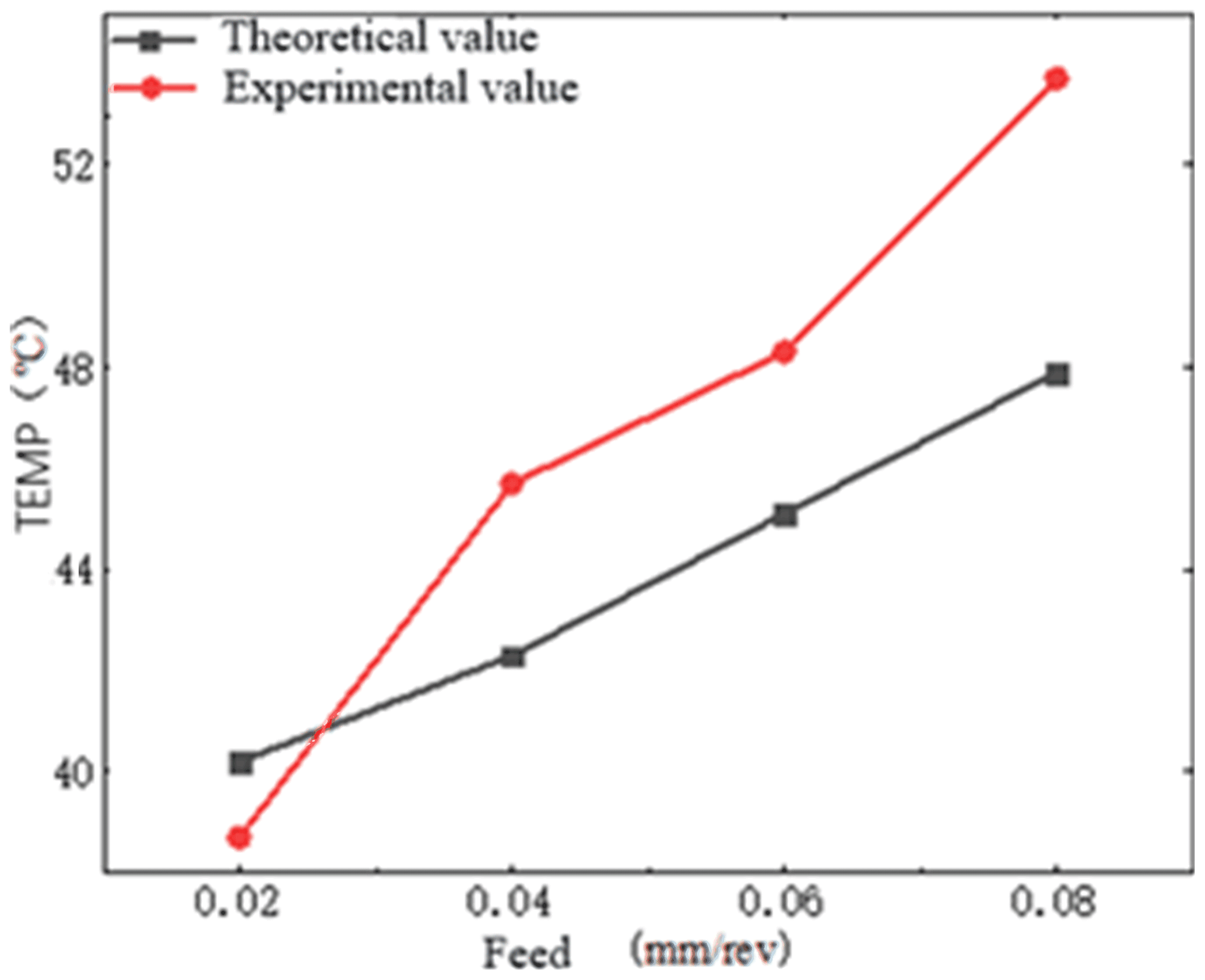
It can be observed from Fig. 13 that the cutting temperature increases with the increase in the feed rate, and both the theoretical and experimental values show an upward trend. When the feed rate is 0.02 mm per revolution, the experimental measured cutting temperature is 38.7 °C, the theoretical temperature is 40.2 °C, the difference is 1.5 °C, and the error is 3.73 %. When the feed rate is 0.04 mm per revolution, the experimental measured cutting temperature is 45.7 °C, the theoretical temperature is 42.3 °C, the difference is 3.4 °C, and the error is 7.44 %. When the feed rate is 0.06 mm per revolution, the experimental measured cutting temperature is 48.3 °C, the theoretical temperature is 45.1 °C, the difference is 3.2 °C, and the error is 6.63 %. When the feed rate is 0.08 mm per revolution, the experimental measured cutting temperature is 53.7 °C, the theoretical temperature is 47.9 °C, the difference is 5.8 °C, and the error is 10.8 %. The maximum error is 10.8 %. The reason for the large error is that, with the increase in the feed rate, the cutting speed in the relative time becomes larger, which increases the cutting amount in a short time; i.e., the theoretical cutting depth increases, resulting in a higher cutting temperature.
3.4 Surface quality analysis
In order to study the effect of ultrasonic vibration-assisted cutting on the surface quality of processed workpieces, under the same cutting parameters (cutting speed of 8 m min−1, feed rate of 0.040 mm per revolution, cutting depth of 0.010 mm), the vibration parameter is 1.41 µm in the amplitude X direction and the Y direction 4.1 µm, with a frequency of 32 KHz. Experiments were conducted on conventional turning and ultrasonic vibration-assisted turning of SiCp Al composite materials with a volume fraction of 25 %. Finally, the surface morphology of the workpiece was observed using a white-light interferometer (ZYGO).
As a special machining material, the SiCp Al composite material is difficult to machine and always causes surface damage during the cutting process due to the presence of internal particles. From Fig. 14, it can be observed that, under the same cutting parameters, the surface of conventional turning can clearly observe the pits caused by particle detachment, the deflection and movement of particles in the matrix, and the scratching and fragmentation of particles caused by the detachment of particles on the machining surface under the action of the tool. Moreover, during conventional cutting, the tool always maintains a cutting state with the workpiece. At this time, tool wear will intensify, which further deteriorates the quality of the machining surface. The surface quality of the UVAC reduces the extraction of particles during cutting and the three-body friction between particles at the chip interface after extraction. Moreover, due to the periodic contact separation motion between the tool and the workpiece in the UVAC, the cutting depth is time-varying, resulting in a low-heat and cutting force generated during the cutting process. At the same time, under the impact of vibration, particles are easier to break and obtain good surface quality.
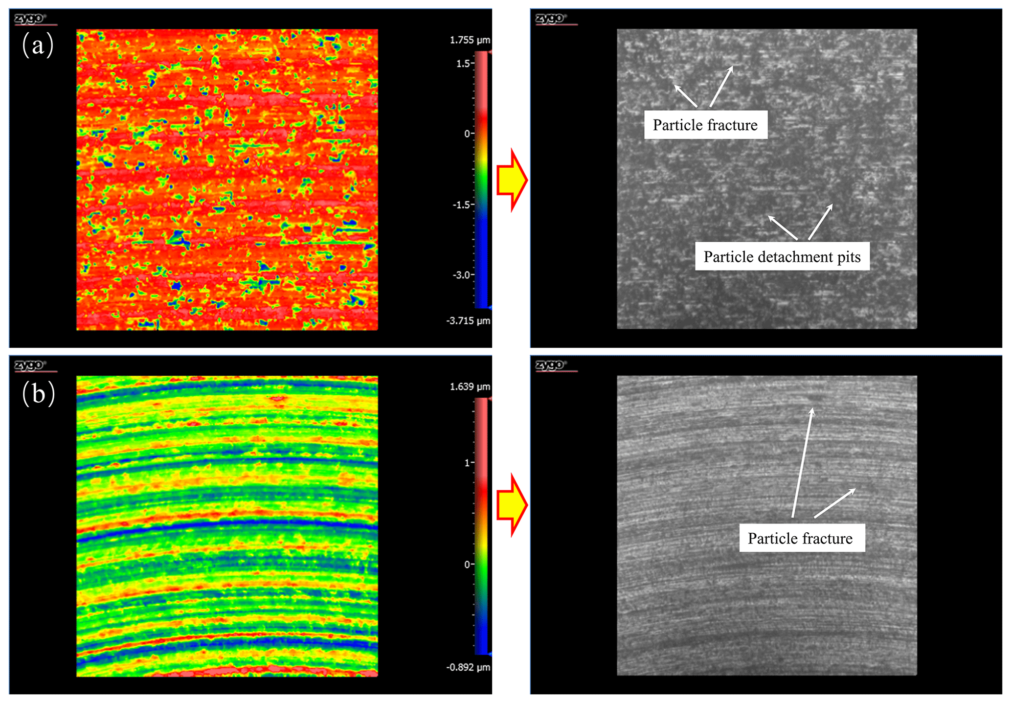
Figure 14Surface morphology of SiCp Al composite materials processed with different cutting methods, (a) conventional turning, and (b) ultrasonic vibration-assisted turning.
In order to investigate the influence of tool elliptical motion on the cutting process during two-dimensional ultrasonic vibration-assisted cutting, this study established a theoretical numerical model based on the instantaneous shear angle and shear surface theory of ultrasonic vibration-assisted cutting. Finite-element software was used for simulation, and ultrasonic vibration-assisted turning of a SiCp Al composite material with a volume fraction of 25 % was carried out on the Nanoform 250 ultra-precision machine tool. The cutting temperature of SiCp Al composite material during the UVAC and conventional cutting processes was analyzed using a thermal imaging device. The conclusion is as follows.
- 1.
When the cutting speed increases from 4 to 16 m min−1, the cutting temperature increases from 41.5 to 53.1 °C. This is because the increase in cutting speed during the turning process leads to an increase in the power consumption of the cutting layer per unit time of the cutting material while also producing more chips and a large amount of heat.
- 2.
When the cutting depth ranges from 0.01 to 0.03 mm, the cutting layer of the workpiece thickens, causing plastic deformation and generating more energy. The cutting temperature increases from 34.8 to 56.7 °C. During the cutting process, as the cutting depth increases, more SiC particles will be damaged and destroyed in different forms, thereby generating energy. At the same time, increasing the cutting depth can also lead to increased tool wear, leading to errors.
- 3.
As the feed rate increases from 0.02 to 0.08 mm per revolution, the relative cutting speed increases, resulting in an increase in the cutting amount in a short period of time, i.e., an increase in the theoretical cutting depth, leading to a cutting temperature from 38.7 to 53.7 °C.
- 4.
Compared with the theoretical model, the maximum errors of the actual cutting temperature values for feed rate, cutting depth, and cutting speed are 10.80 %, 11.46 %, and 9.88 %, respectively, which verifies the effectiveness of the theoretical model within a reasonable range. At the same time, due to the periodic contact separation motion between the tool and the workpiece in UVAC, the cutting depth is time-varying. Under the impact of vibration, particles are easier to break and obtain good surface quality. This indicates that the model can be applied to temperature prediction research in ultrasonic-assisted cutting of composite materials, providing a reference for future research on composite material processing mechanisms.
The basic research data for this study will not be disclosed further.
QW: conceptualization. SZ: writing – review and editing. YD: data curation. DY: writing – original draft preparation. YY: validation.
The contact author has declared that none of the authors has any competing interests.
Publisher's note: Copernicus Publications remains neutral with regard to jurisdictional claims made in the text, published maps, institutional affiliations, or any other geographical representation in this paper. While Copernicus Publications makes every effort to include appropriate place names, the final responsibility lies with the authors.
This project is supported by the Natural Science Foundation of Jilin Province (grant no. YDZJ202201ZYTS534) and the Jilin Provincial International Cooperation Key Laboratory for High-Performance Manufacturing and Testing (grant no. 20220502003GH).
This paper was edited by Jeong Hoon Ko and reviewed by two anonymous referees.
Jamil, M., He, N., Zhao, W., Kumar Gupta, M., and Mashood Khan, A.: Novel Approach of Cutting Temperature Measurement in Sustainable Milling of Ti-6Al-4V Alloy, Measurement, 214, 112837, https://doi.org/10.1016/j.measurement.2023.112837, 2023.
Li, Q., Yuan, S., Gao, X., Zhang, Z., Chen, B., Li, Z., and Batako, A. D. L.: Surface and subsurface formation mechanism of SiCp Al composites under ultrasonic scratching, Ceram. Int., 49, 817–833, https://doi.org/10.1016/j.ceramint.2022.09.055, 2023.
Liu, J., Li, J., and Xu, C.: Interaction of the cutting tools and the ceramic-reinforced metal matrix composites during micro-machining: A review, CIRP Journal of Manufacturing Science and Technology, 7, 55–70, https://doi.org/10.1016/j.cirpj.2014.01.003, 2014.
Liu, W., Li, G., Shao, Z., Wu, X., Ma, G., and Wang, F.: Advance in experimental research on cutting temperature of titanium alloys, Int. J. Adv. Manuf. Tech., 126, 1827–1844, https://doi.org/10.1007/s00170-023-11263-x, 2023.
Longbottom, J. M. and Lanham, J. D.: A review of research related to Salomon's hypothesis on cutting speeds and temperatures, Int. J. Mach. Tool. Manu., 46, 1740–1747, https://doi.org/10.1016/j.ijmachtools.2005.12.001, 2006.
Lu, M., Zhou, X., and Lin, J.: Improved memetic algorithm for nonlinear identification of a three-dimensional elliptical vibration cutting system, P. I. Mech. Eng. I-J. Sys., 228, 449–460, https://doi.org/10.1177/0959651814530276, 2014.
Lu, S., Li, Z., Zhang, J., Zhang, J., Wang, X., Yan, Y., and Sun, T.: Finite element investigation of the influence of SiC particle distribution on diamond cutting of SiCp Al composites, Nanomanufacturing and Metrology, 3, 251–259, https://doi.org/10.1007/s41871-020-00074-3, 2020.
Meng, X. X. and Lin, Y. X.: Chip morphology and cutting temperature of ADC12 aluminum alloy during high-speed milling, Rare Metals, 40, 1915–1923, https://doi.org/10.1007/s12598-020-01486-2, 2020.
Pramanik, A.: Developments in the non-traditional machining of particle reinforced metal matrix composites, Int. J. Mach. Tool. Manu., 86, 44–61, https://doi.org/10.1016/j.ijmachtools.2014.07.003, 2014.
Saez-de-Buruaga, M., Soler, D., Aristimuño, P. X., Esnaola, J. A., and Arrazola, P. J.: Determining tool/chip temperatures from thermography measurements in metal cutting, Appl. Therm. Eng., 145, 305–314, https://doi.org/10.1016/j.applthermaleng.2018.09.051, 2018.
Song, W., Wang, Z., Wang, S., Zhou, K., and Guo, Z.: Experimental study on the cutting temperature of textured carbide tool embedded with graphite, Int. J. Adv. Manuf. Tech., 93, 3419–3427, https://doi.org/10.1007/s00170-017-0683-5, 2017.
Su, G., Xiao, X., Du, J., Zhang, J., Zhang, P., Liu, Z., and Xu, C.: On cutting temperatures in high and ultrahigh-speed machining, Int. J. Adv. Manuf. Tech., 107, 73–83, https://doi.org/10.1007/s00170-020-05054-x, 2020.
Teng, X. and Wierzbicki, T.: Evaluation of six fracture models in high velocity perforation, Eng. Fract. Mech., 73, 1653–1678, https://doi.org/10.1016/j.engfracmech.2006.01.009, 2006.
Verma, G. C., Pandey, P. M., and Dixit, U. S.: Modeling of static machining force in axial ultrasonic-vibration assisted milling considering acoustic softening, Int. J. Mec. Sci., 136, 1–16, https://doi.org/10.1016/j.ijmecsci.2017.11.048, 2018.
Wang, Y. F., Liao, W. H., Yang, K., Teng, X., and Chen, W.: Simulation and experimental investigation on the cutting mechanism and surface generation in machining SiCp Al MMCs, Int. J. Adv. Manuf. Tech., 100, 1393–1404, https://doi.org/10.1007/s00170-018-2769-0, 2019.
Zha, H., Feng, P., Zhang, J., Yu, D., and Wu, Z.: Material removal mechanism in rotary ultrasonic machining of high-volume fraction SiCp Al composites, Int. J. Adv. Manuf. Tech., 97, 2099–2109, https://doi.org/10.1007/s00170-018-2075-x, 2018.
Zheng, W., Wang, Y., Zhou, M., Wang, Q., and Ling, L.: Material deformation and removal mechanism of SiCp Al composites in ultrasonic vibration assisted scratch test, Ceram. Int., 44, 15133–15144, https://doi.org/10.1016/j.ceramint.2018.05.150, 2018.
Zheng, W., Qu, D., and Qiao, G.: Multi-phase modeling of SiC particle removal mechanism in ultrasonic vibration–assisted scratching of SiCp Al composites, Int. J. Adv. Manuf. Tech., 113, 535–551, https://doi.org/10.1007/S00170-021-06675-6, 2021.
Zhou, J., Lu, M., Lin, J., Zhou, X., Du, Y., Wang, C., and Diao, Y.: Investigation and simulation based on mesoscopic model of SiCp Al composites during precision machining: deformation mechanism and surface quality, Int. J. Adv. Manuf. Tech., 119, 2173–2186, https://doi.org/10.1007/S00170-021-08407-2, 2022.
Zhou, Y., Gu, Y., Lin, J., Zhao, H., Liu, S., Xu, Z., Yu, H., and Fu, X.: Finite element analysis and experimental study on the cutting mechanism of SiCp Al composites by ultrasonic vibration-assisted cutting, Ceram. Int., 48, 35406–35421, https://doi.org/10.1016/j.ceramint.2022.08.142, 2022.