the Creative Commons Attribution 4.0 License.
the Creative Commons Attribution 4.0 License.
 | 02 May 2024
Structural design and experimental research of a micro-feed tool holder based on topology optimization
Kuipeng Zhao
Dongming Li
Weidong Guo
Ruize Ma
Ziyi Shan
Feng Wang
In the present study, a new configuration for a micro-feed tool rest driven by piezoelectric ceramics with a rigid–flexible phase is designed. The flexible driving part of the micro-feed tool rest is optimized using the topology optimization method, which not only improves the driving stiffness, resolution and structural stability but also increases the maximum displacement. The structural stiffness achieved in finite element simulation analysis is 16.28 N µm−1, and the first natural frequency reaches 2521 Hz. A prototype of a piezoelectrically driven micro-feed tool holder and a testing platform are constructed, and the structural stiffness of the prototype is determined to be 15.53 N µm−1 via analysis and testing, resulting in an error of 4.8 % compared with the finite element simulation results. The first-order natural frequency is 2636 Hz given a resolution of 12 nm and a maximum output displacement of 12.983 µm. Compared with the double-parallel flexible hinge, the maximum stroke of the micro-feed tool holder increases by about 5.4 µm and the resolution is improved by about 50 %. The new micro-feed tool holder developed in this paper features a cross-plate-type flexible mobile guiding mechanism. Combining stiffness, maximum travel and displacement resolution, it is applicable to precision and ultra-precision machining.
- Article
(5275 KB) - Full-text XML
- BibTeX
- EndNote


As a kind of ultra-precision machining technology (Lucca et al., 2020; Chang et al., 2020; Gong et al., 2022; J. Guo et al., 2022; Shindo and Nishiwaki, 2020), fast tool servo (FTS) single-point diamond cutting technology has various advantages, like a fast response time and high machining accuracy. By loading the fast tool servo system on the feed platform of ultra-precision machine tools, the surface can be machined to submicron accuracy (Wang et al., 2021). The optical components with nanoscale surface roughness do not require grinding or polishing, providing one of the most promising methods of machining for aspherical (Aris and Cheng, 2008; Paniselvam et al., 2023), asymmetrical rotary optical surfaces and micro-structured functional surfaces. Piezoelectric ceramic micro-feed tool holders (Zhao et al., 2020) rely on the piezoelectric ceramic inverse piezoelectric effect to achieve a high-frequency precision micro-drive, which leads to such advantages as a fast response time and high stiffness. As a major part of the fast tool servo system, it is capable of improving the accuracy of the feed system cutting positioning. With a short stroke, a piezoelectrically driven micro-feed tool holder usually requires reduced flexibility to improve the drive stroke. However, this tends to reduce the resonance frequency of the tool holder, significantly affecting the frequency bandwidth of the tool holder, compromising the structural stiffness, and reducing both the output displacement and machining accuracy (Paniselvam et al.,2023).
Since the Lawrence Livermore National Laboratory in the United States first proposed the concept of fast tool servo (Patterson and Magrabt, 1985; Huang et al., 2020; Nagayama and Yan, 2021), countries around the world have carried out in-depth research on this technology (Kim et al., 2017; Yong et al., 2020; Y. J. Guo et al., 2022; Guan et al., 2020; Yoshioka et al., 2020; Pelic et al., 2021). For instance, Huo and Cheng (2008) from Brunel University London in the United Kingdom developed a set of piezoelectrically driven flexure hinge micro-feed devices to achieve precision machining on the surface of an aluminium workpiece, the roughness of which was less than 10 nm. Despite the high resolution of the tool system, the improvement in the accuracy led to insignificant displacement. Rakuff and Cuttino (2009) from the University of North Carolina at Charlotte developed a Lorentz force micro-feed tool rest device (Rakuff and Cuttino, 2009), which comprised a voice coil motor as the driver and a flexible hinge as the guide mechanism, to process earlobe non-rotary symmetrical surfaces. In addition to a maximum travel range of 1 mm and a frequency response of only 140 Hz, the device also had a small bandwidth. However, high-frequency processing was not achievable and a larger stroke could be achieved only in the context of low resolution. Kim and Nam (1997) from Korea Robot Manufacturing Technology Center also studied a fast knife servo system (Kim and Nam, 1997). With a capacitance sensor as the tool displacement feedback, the displacement output was only 7.5 µm, and the output displacement was limited. Li (2006) from Tianjin University built a displacement-oriented micro-feed tool rest configuration based on double-parallel flexible hinges (Li, 2006). The travel range of the tool holder was 7.58 µm, the resolution was 8 nm, the natural frequency was 1123 Hz and the displacement was insignificant. Duan (2011) from Jilin University developed a micro-feed tool holder with 2 degrees of freedom. Despite a stroke of 12.72 µm, the static stiffness was as low as 6.7 N µm−1, thereby restricting the drive resolution. The structure of the micro-feed tool holder has a considerable effect on the performance in terms of stiffness, displacement and resolution, which are closely related to the accuracy of machining and the quality of the workpiece. Given a higher stiffness of the tool holder, the stability and machining accuracy of the system can be ensured. However, excessive rigidity reduces flexibility, resulting in a corresponding reduction in output displacement and, thus, a decrease in the displacement, accuracy and stability of the entire structure (Poulsen, 2002; Liu et al., 2023).
In this paper, a new configuration of a micro-feed tool rest, which is driven by piezoelectric ceramics, is presented, and the flexible parts of the micro-feed tool rest are optimized using the topology optimization method. In the presence of a symmetrical cross-plate flexible moving pair, the rigid–flexible phase of the tool rest structure is obtained to ensure the long-range travel of the flexible mechanism. Meanwhile, driving stiffness, resolution and structural stability are improved. The stiffness, displacement, stress and modal characteristics of the entire micro-feed tool rest are analysed via simulation. Finally, a micro-feed tool holder prototype is produced to evaluate its performance in terms of stiffness, output displacement and resolution.
2.1 Design and topology optimization of an inching tool rest
The motion of a micro-feed tool holder is enabled by the elastic deformation occurring in the elastic element driven by piezoelectric ceramics; thus, the topology optimization of the micro-feed tool holder is to optimize the compliant mechanism topologically (Teng et al., 2022; Zhao et al., 2023; Yuksel et al., 2020). On the one hand, the compliant mechanism is supposed to be sufficiently flexible to achieve the expected working stroke; on the other hand, it should be stiff enough to ensure its working stability.
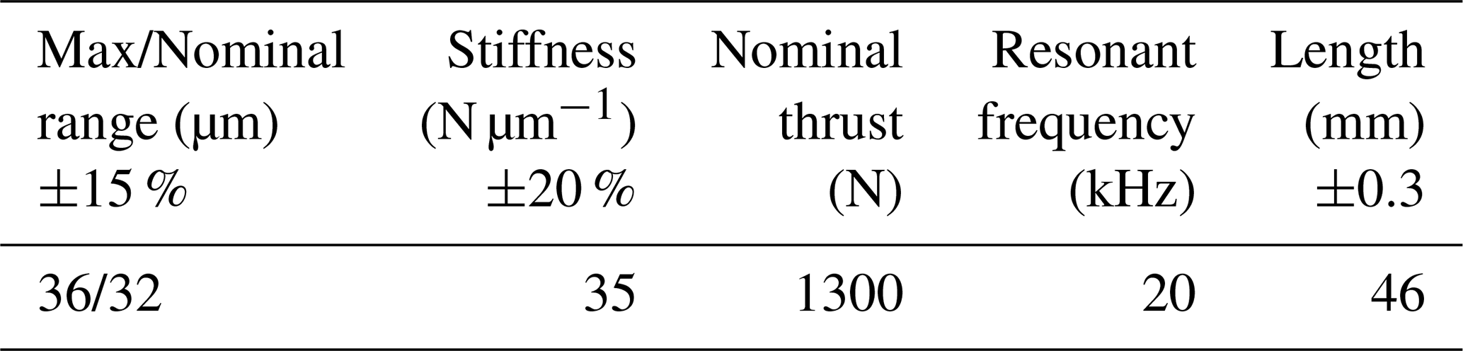
Overall, the micro-feed tool holder consists mainly of a tool holder base, a driver, a guide mechanism, a measurement device and a cutting tool. Among them, the actuators and steering mechanisms are the most important. To satisfy the design requirements, the 40VS12 low-pressure cylindrical flat-head self-sensing piezoelectric ceramic driver sourced from Harbin Core Tomorrow Technology Co., Ltd. is selected as the driving mechanism for the micro-feed tool holder system. Its performance parameters are listed in Table 1. The diameter of the piezoelectric ceramics is 12 mm.
Table 1Performance parameters of the piezoelectric ceramic actuator.
The capacitive displacement sensor possesses a range of advantages, such as structural simplicity, high temperature stability, excellent adaptability, high sensitivity and robust dynamic performance. The capacitive displacement sensor is applied to measure the output displacement at the tool front end. The diameter of the sensor is 10 mm, the resolution is 2.5 nm and the range is 0–200 µm.
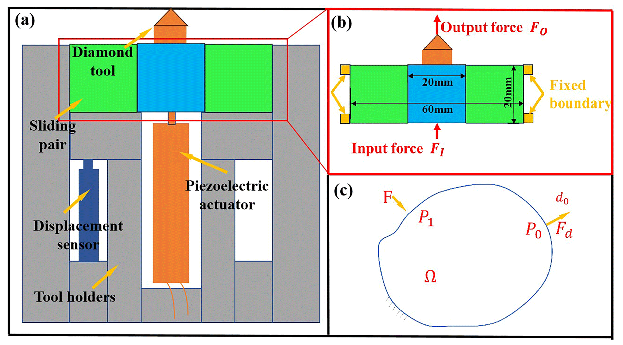
Figure 1Panel (a) presents the overall structure of the tool holder, panel (b) shows the optimization area and panel (c) outlines the topology optimization schematic.
As shown in Fig. 1a, the diamond tool is fixed at the front end of the tool and secured by two bolts. Positioned in an empty slot in the middle of the tool holder, the lead zirconate titanate piezoelectric ceramic (PZT) is evidently neutral and is secured by pre-tightened bolts at the rear end of the tool. The part in dark blue in Fig. 1 indicates a capacitive displacement sensor. The output displacement of the cutter is controlled by the piezoelectric control power supply. In order to measure the displacement of the tool holder, a gap is created between the capacitance sensor and the measurement baffle extended from the front end of the tool holder. During the measurement, the capacitance sensor is tightened using the left bolt. Through the mounting hole, the tool holder can be mounted with ease on the feed platform of the machine tool. Fit for experimental ultra-precision machining, micro-feed tool holders can also be applied to micro-equipment and micro-positioning systems.
As a branch of structural optimization, topology optimization aims to assist designers in determining the best material layout under certain loads and constraints at the initial stage of structural design. Herein, the relevant assumptions made for non-topologically optimized regions are proposed. They are assumed to be the regions that are rigid and incompressible, with no energy loss occurring during operation. Firstly, the optimization area is defined and the optimization objectives, constraints and load conditions are set. The topology optimization area is indicated by a green area in Fig. 1b, consisting of two 20 mm × 20 mm rectangles. A force (F) of 100 N is applied at a point in the middle of the moving pair. Then, finite element analysis is performed on the initial design variables, and the sensitivity of the optimization function is analysed. Based on the analysis results, the criterion method is used to iteratively update the design variables to determine whether convergence is achieved. Ultimately, a topology map is drawn.
Depending on the exact object, topology optimization is divided into discrete structure topology optimization and continuum structure topology optimization. Continuum structure topology optimization method should be used when the optimal design area of the tool holder is a finite continuum. At present, the mainstream solution to establish a continuum topology optimization mathematical model is the SIMP (solid isotropic material with penalization) variable-density method (Rietz, 2001). Based on isotropic materials, it assumes that the materials in the design area are composed of solid elements with a relative density between 0 and 1. The relative density of each solid element is taken as a design variable to determine the relative density of the solid elements and to establish the relationship between the material elastic matrices. The SIMP method is expressed as follows:
where ρi represents the density of structural elements, with ρi = 1 representing an entity and ρi=0 representing a hole; E(ρi) indicates the elastic modulus after material interpolation; E0 and Emin are referred to as the elastic modulus of the material entity and the hole, respectively; and P denotes the density penalty factor, with P > 1. On this basis, an exponential relationship is established between the elastic modulus of the material and the density function of the material. By introducing the density penalty factor P to constrain the intermediate density, the optimization variables perform better in approaching the 0–1 discrete optimization model, as shown in Fig. 1c.
Strain energy usually indicates the stiffness of the mechanism, with a smaller strain energy meaning a greater stiffness under a given driving load. The strain energy of the mechanism under the action of load F is expressed as follows:
where ε(u) represents the strain under the action of load F, u indicates the elastic deformation of any point in the design field under the action of load F, D is referred to as the elastic matrix, U denotes the node displacement vector under the action of load F and K stands for the structural stiffness matrix. The displacement vector U is calculated by the finite element method below:
The flexibility of the structure is manifested as mutual strain energy. The greater the strain energy, the higher the flexibility of the structure. Then, the mutual strain energy of the structure is expressed as follows:
where ε(ud) is the strain under virtual load Fd, ud is the elastic deformation occurring at any point in the design domain under the virtual load Fd and Ud is the node displacement vector under the action of virtual load Fd. Ud can be known from the following equation:
The flexibility and stiffness of the structure must be carefully considered in the design of the compliant mechanism. At present, the ratio method is usually adopted to establish the mathematical model for topologically optimizing the compliant mechanism, as shown in Eq. (6); this is the mathematical model used to topologically optimize the flexible part of the tool rest.
Considering the requirements of practical applications, as shown in Fig. 1a, a new type of micro-feed tool holder has been developed with a piezoelectric ceramic actuator as the driver and a symmetrical cross-plate flexible-motion pair as the guiding mechanism. This micro-feed tool holder is capable of linear displacement output in the direction of feed, with high accuracy achieved in the output displacement positioning. At the same time, it demonstrates various advantages, like structural simplicity and compactness as well as ease of processing, manufacture and assembly.
The flexible part at the front end of the tool rest plays a major role in the overall performance of the tool rest, which restricts the optimization process with respect to this part. Figure 1b illustrates the topology optimization of the micro-feed tool holder, and its optimization mathematical model has been described above. In Fig. 1b, the green area indicates the optimization region, while the blue area indicates the non-optimization region for the location of tool clamping. The four yellow areas are fixed boundaries. The constraint is purposed to apply fixed constraints on both sides, and a concentrated force of 100 N is applied to the middle rigid body part. The bottom of the moving pair is subjected to both input force and output force at the diamond tool head. The material density in the non-optimization region remains unchanged throughout the optimization process. The aim of design is as follows: when the piezoelectric ceramic driving force F acts, output displacement occurs accordingly at the front end of the tool holder; when the output displacement meets certain conditions, the structural rigidity reaches its maximum.
After the general structure of the micro-feed tool holder is determined, ANSYS software is applied to conduct finite element analysis on its mechanical properties. To a large extent, the accuracy of machining is determined by the dynamic response performance of the micro-feed tool rest and its natural frequency. Therefore, it is necessary to carry out static analysis and kinematic analysis on the designed tool rest. Only in this way can it be determined if the structural parameters of the tool rest are designed in a reasonable way. Prior to the analysis, the main parameters were set correctly, such as the elastic modulus, density and Poisson's ratio. In order to improve the timeliness of the analysis, the finite element model is simplified and some factors are discounted from the analysis, such as threaded holes. Intelligent grid division is performed for the overall structure of the knife rest.
2.2 Overall testing platform for the micro-feed tool holder
In order to ensure the high quality of machining, wire cutting is adopted. Allowing for the specific structure of the previously designed tool holder, static and dynamic performance tests are conducted to verify if it complies with the requirements of ultra-precision machining. The metrics of these tests include stiffness, output displacement and resolution. Figure 2 shows a complete flowchart of the testing process.
3.1 Optimization results of the cross-plate flexible moving pair
A 65Mn spring steel material is used to design the tool rest with consideration given to the flexibility and rigidity of the micro-feed tool rest. This material shows an elastic modulus of 200 GPa, a Poisson's ratio of 0.3 and a density of 7800 kg m−3. After being discretized, the grid of the established tool rest model is solved iteratively under the relevant boundary constraints and load conditions to obtain the final results of topology optimization for the micro-feed tool holder at the front end. In ANSYS 15.0, a finite element model of a cross-plate flexible moving pair is established. The parameters of the model are detailed as follows: the material is in the class of 65Mn, E = 200 GPa, μ = 0.3, t = 1.06 mm, l = 4.24 mm, L = 23.33 mm and b = 20 mm. With the rigid parts on both sides of the moving pair fully constrained, a force F of 100 N is applied at a point in the middle of the moving pair.
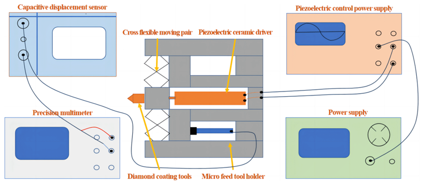
Figure 3Panel (a) presents the optimization results, panel (b) shows the initial model simulation deformation map, panel (c) displays the cross-plate flexible moving pair and panel (d) outlines the finite element analysis model.
A diagram of topology optimization results is obtained and extracted. At the same time, the modelling–simulation process is conducted in several rounds in accordance with the mechanical analysis theory of structural mechanics and the actual processing and application requirements. Finally, the cross-plate-type flexible moving pair is designed, as shown in Fig. 3a.
The initial model constructed through finite element simulation analysis was used to analyse the stiffness and maximum stress of flexible moving joints. Thus, the maximum deformation caused to the structure occurs when the external load reaches 100 N, as shown in Fig. 3b. Also, the maximum deformation of the initial model is 0.70212 µm, the stiffness is 142.42 N µm−1 and the maximum stress is 4.07 MPa. In this case, the displacement caused by the moving pair is insignificant, making it difficult to meet the target requirements.
By reanalysing the optimization result graph and applying the mechanical analysis theory of structural mechanics, softening treatment was conducted for the cross-plate flexible moving pair. After multiple rounds of design and simulation, the Z-shaped cross-plate flexible moving pair (as shown in Fig. 3c) was finalized to comply with the practical requirements of processing and application. This novel mechanism improves both the stiffness of the structure and the accuracy of machining when the output displacement satisfies certain conditions. From above, it can be seen that the Z-shaped cross-plate flexible moving pair is produced by topology optimization to build the original linear cross-plate moving pair. After further analysis and softening treatment, the Z-shaped cross-plate flexible moving pair is built. Under the same model parameters, via solving, the deformation cloud map of the flexible moving pair is obtained (as shown in the Fig. 3d). Under the same conditions, there is a significant increase in displacement.
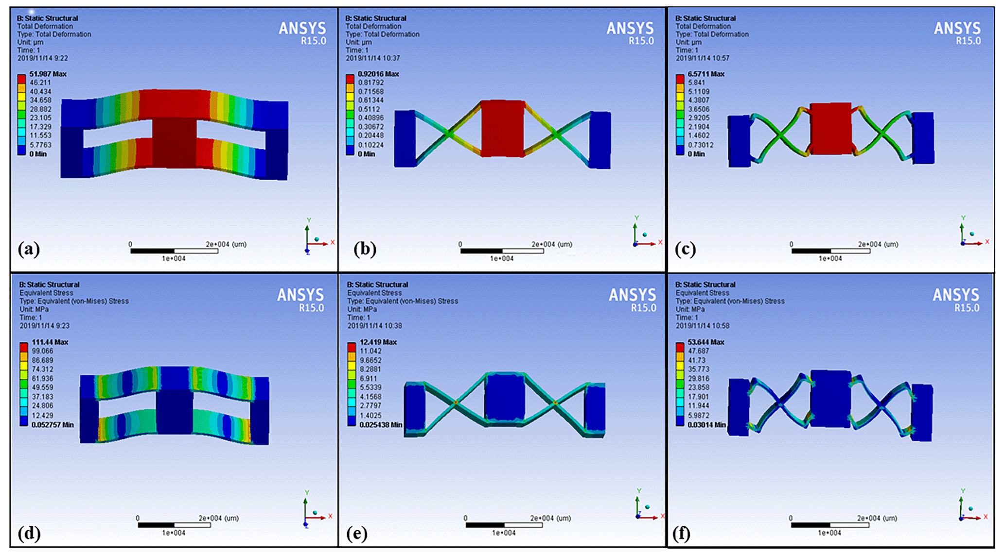
Figure 4Panel (a) presents a deformation cloud map of a parallel-plate-type moving pair, panel (b) shows a deformation cloud map of a cross-plate-type moving pair, panel (c) displays a deformation cloud map of a new cross-plate-type mobile pair, panel (d) presents a stress distribution cloud map of a parallel-plate-type moving pair, panel (e) shows a stress distribution cloud map of a cross-plate-type moving pair and panel (f) displays a stress distribution cloud map of a new cross-plate-type mobile pair.
Finite element analysis was conducted to comparatively analyse the deformation of parallel-plate (traditional model), straight cross-plate (topology optimization initial model) and Z-shaped cross-plate (newly proposed structural model) flexible moving pairs using the same geometric parameters. Figure 4 shows the simulation cloud maps of the three types of flexible moving pairs, and their results are shown in Table 2. The maximum deformation of the parallel-plate-type moving pair is 51.98 µm, and the maximum stress is 114.44 MPa. In this case, the natural frequency is 1189 Hz (Fig. 4a, d). The maximum deformation of the cross-plate-type moving pair is 0.92 µm, and the maximum stress is 12.42 MPa. As shown in Fig. 4b and e, the natural frequency is 9359 Hz. The maximum strain of the new cross-plate-type mobile pair is 6.57 µm, and the maximum stress is 53.64 MPa. In this context, the natural frequency is 4676 Hz (Fig. 4c, f).
Via analysis, it can be concluded that, given the same thickness and load constraints, the parallel-plate flexible moving pair is subjected to the maximum deformation, showing a greater sensitivity to low-level external excitation. However, its natural frequency is low, which can easily cause resonance. Despite the relatively high natural frequency of the cross-plate-type moving pair, the displacement is insignificant. This novel plate-flexible mobile joint achieves excellent performance, complying with the requirements on deformation and stiffness.
3.2 Theoretical calculation of the stiffness of the tool holder structure
The stiffness equation of a flexible moving joint was derived by applying the rationales of material mechanics. Given the symmetry of the cross-plate flexible moving pair and the stress analysis of it, it is sufficient to calculate only one symmetrical part. A mechanical calculation model is established according to the one-quarter structure of the flexible moving pair, as shown in Fig. 5b.
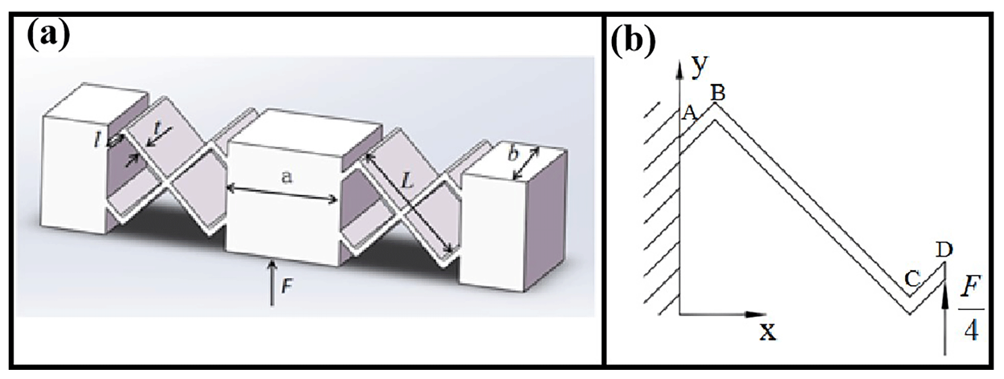
Figure 5Panel (a) presents a cross-moving substructure model and panel (b) shows the computation model.
According to the displacement calculation formula of planar bar systems under load in structural mechanics, as shown in Eq. (7), the three items on the right-hand side of the equation represent the total displacement of the structure under axial load, bending load and shear load, respectively. The structural displacement in this article is mainly caused by bending deformation, and the influence of axial deformation and shear deformation is relatively small, so it is simplified as shown in Eq. (8).
Here, E represents the elastic modulus of the material and I indicates the moment of inertia possessed by the transverse plane of the flexible part towards the central axis. From the rectangular cross-section of the cross-plate moving pair, it can be known that .
With a vertical unit load at point D as a virtual state, a bending moment diagram of the structure is drawn. Furthermore, the displacement occurring at point D is calculated using the graph multiplication method. Based on Hooke's law, the formula of stiffness calculation can be obtained as follows:
Considering that the loaded flexible moving joint undergoes not only bending deformation but also axial deformation in the transverse direction, the formula of stiffness correction for the flexible moving joint can be obtained by analysing the generalized Hooke's theorem in mechanics as follows:
where μ represents the Poisson's ratio of the material.
The theoretical calculation value of the stiffness of the tool holder structure can be obtained by using the stiffness correction (Eq. 10), which is 16.83 N µm−1.
3.3 Statics analysis of the tool rest
In the course of stress analysis, the output displacement of the tool rest is affected mainly by the deformation caused to the flexure hinge. In order to prevent the hinge from breaking due to stress concentration during service, it is necessary to conduct stress analysis to determine when the tool rest reaches its maximum output displacement and if the maximum stress of the mechanism is exceeded by the allowable stress of the material. Figure 6b shows the stress distribution cloud map created when the maximum output displacement occurs for the tool holder. Obviously, the maximum stress is 139.62 MPa, which is far below the allowable stress of the material.
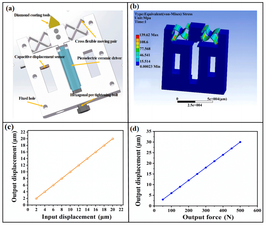
Figure 6Panel (a) presents the overall structure of the micro-feed tool holder, panel (b) shows a stress cloud map, panel (c) outlines relationship between the input displacement and output displacement, and panel (d) outlines relationship between the input force and output displacement.
During displacement analysis, the tool holder is fixed on the left and right sides and displacement is allowed to occur along the feed direction on the surface of contact between the piezoelectric ceramic driver and the front end of the tool holder, varying from 0 to 20 with an increment of 2. Via analysis, the relationship between the input displacement of piezoelectric ceramics and the output displacement of the tool holder is determined, as shown in Fig. 6c. It can be seen from the figure that there is an evident linearity in the input displacement of piezoelectric ceramics and the output displacement of tool rest, which indicates the high guiding accuracy of the guiding mechanism and the rationality of the design.
During stiffness analysis, a concentrated force of 0–500 N is applied at an increment of 50 N to the tool rest. As shown in Fig. 6d, a finite element analysis is carried out to determine the relationship between tool rest force and output displacement. The stiffness is calculated to be 16.28 N µm−1. The calculated value is very close to the theoretical value.
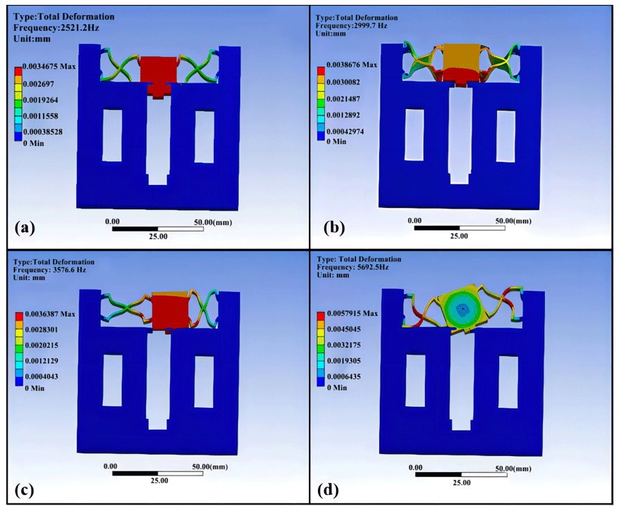
In order to protect the tool rest from damage caused by resonance during machining, modal analysis is required. Figure 7 shows the mode of vibration.
According to the results of modal analysis, the first natural frequency of the micro-feed moving tool holder is 2521.2 Hz, the second one is 2999.7 Hz, the third one is 3576.5 Hz and the fourth one is 5692.5 Hz. In the machining process, the mechanical structures are prone to resonance when the operating frequency ranges from 800 to 1500 Hz. These results demonstrate that the natural frequency of the tool holder far exceeds its operating frequency, with a significant dynamic stiffness shown in the feed direction of the tool holder. This is effective in eliminating the impact of vibration.
3.4 Performance testing of the micro-feed tool holder
According to the design of the tool holder structure (as mentioned in Sect. 2), the micro-feed tool holder is developed to ensure high-quality processing, as shown in Fig. 8a. For this purpose, wire cutting is performed.
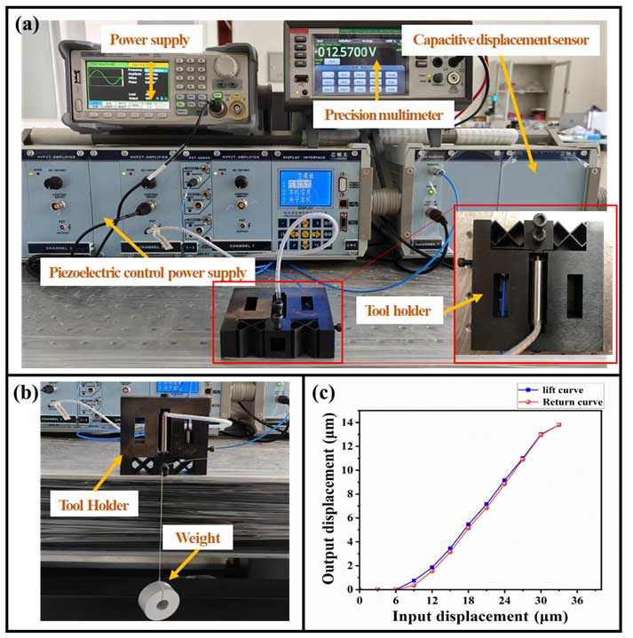
Figure 8Panel (a) presents the tool holder displacement wiring diagram and physical diagram, panel (b) shows the stiffness test, and panel (c) displays the input displacement and output displacement characteristic curves.
To conduct a stiffness test, the micro-feed tool holder is placed vertically on the isolation platform, with the displacement of the tool holder in the feed direction achieved by hanging a weight at the tool base. Then, the displacement is measured by the sensor. The voltmeter is a DMM7510 digital multimeter, whose accuracy reaches up to 0.01 mV. The test wiring diagram is shown in Fig. 8b, and the structural stiffness of the tool rest is calculated theoretically; the tool holder is calculated to have a stiffness of 16.83 N µm−1. The structural stiffness measurement results for the micro-feed tool rest are listed in Table 3.
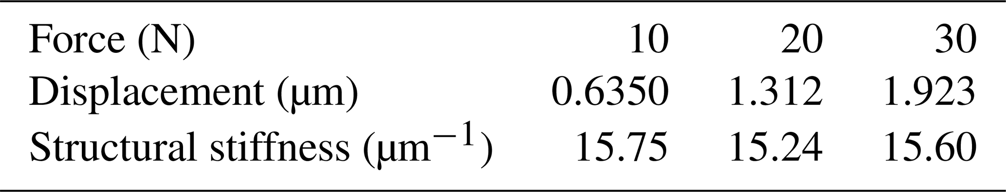
By averaging the three groups of test data (as shown in Table 3), the structural stiffness of the micro-feed tool rest is determined to be 15.53 N µm−1, with an error of 8.3 % relative to the results of theoretical calculation and of 4.8 % compared with the results of numerical simulation. The experimental results are basically consistent with the theoretical calculation and numerical simulation results, implying the correctness of the theoretical calculation and simulation analysis.
In the output displacement test, the input displacement of the micro-feed tool holder is enabled by the piezoelectric ceramic controller in the closed-loop state, and the output displacement occurring at the front end of the tool holder is measured. Figure 8a shows the wiring diagram of the testing process. Figure 8c shows the measured closed-loop feed curve of the tool rest. According to this figure, the maximum output displacement of the micro-feed tool holder is 12.983 µm in the closed-loop control state given an input displacement of 30 µm. At the same time, the lift curve and the return curve fit well with neither hysteresis nor creep observed. However, the applied pre-tension causes zero drift of the PZT driver under the context of closed-loop control.
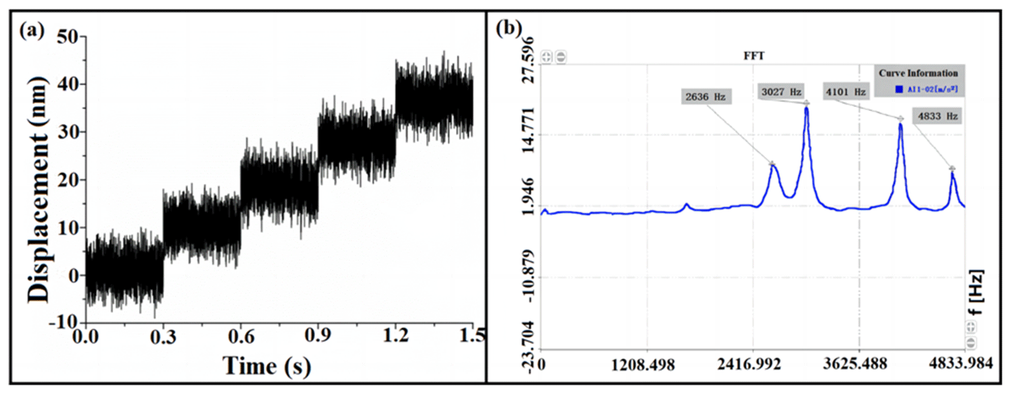
During the experimental test of the resolution and natural frequency, a displacement with an increment of 50 nm is input into the micro-feed tool holder system in a closed-loop state. The experimental results are shown in Fig. 9a, indicating that the resolution of the micro-feed tool holder reaches approximately 12 nm.
According to the results of dynamic analysis, resonance may occur when the frequency of the external excitation force becomes comparable to the natural frequency of the machine tool workpiece system. Resonance causes the driving device and detection device of the machine tool to malfunction, which affects the accuracy of machining significantly and even causes damage to the workpiece and the tool. Therefore, it is necessary to eliminate resonance from the machining process by testing the natural frequency of the workpiece system. During the test, the micro-feed tool holder is suspended with elastic string and struck evenly with a hammer to produce a shock. Figure 9b shows the results of natural frequency test on the micro-feed tool holder as obtained through spectrum analysis. According to the test results, the natural frequency of the micro-feed tool rest in the direction of the cutting feed is 2636 Hz, and the error compared with the finite element simulation results is close to 4.36 %.
In the present study, a novel configuration for a piezoelectric ceramic drive micro-feed tool rest with both rigid and flexible phases is designed. The flexible part of the micro-feed tool rest is optimized by means of topology optimization, and the flexible mobile auxiliary guiding mechanism of a new symmetrical cross-plate type is developed, which not only improves the driving stiffness, resolution and structural stability but also increases the maximum displacement. The finite element method is applied to simulate the stiffness, displacement, stress and mode of the whole micro-feed tool rest. The simulation results show that the structural stiffness is 16.28 N µm−1, the first-order natural frequency is 2521 Hz and the maximum stress is 139.62 MPa, which is far below the allowable stress of the material. A piezoelectric drive micro-feed tool holder prototype is constructed, a test platform is built, and the stiffness and displacement properties of the micro-feed tool holder are experimentally studied. The structural stiffness of the tool rest is 15.53 N µm−1, and the error compared with the result of finite element simulation is 4.8 %. The maximum output displacement under closed-loop control is 12.983 µm, the first-order natural frequency is 2636 Hz and the resolution is 12 nm. Compared with the double-parallel flexible hinge, the maximum distance travelled by the micro-feed tool holder increases by about 5.4 µm, and the resolution is improved by about 50 %. The results show that the micro-feed tool holder with the new cross-plate-type flexible moving pair as the guiding mechanism is effective with respect to improving the rigidity and resolution of the system. By taking the output displacement into account, the frequency bandwidth of the system is expanded, which makes it applicable to precision and ultra-precision machining.
The code and data generated during this study are available from the corresponding author upon reasonable request.
KZ was responsible for most of the investigation, the methodology development, the data collection and analysis, and writing and editing the manuscript. DL was responsible for resource acquisition, supervising the project, and revising the manuscript. WG helped to carry out most of the experimental tests and edited the manuscript. RM, ZS and FW helped to edit the article. FW provided test instruments and test methods. All authors provided comments on the revision of the manuscript.
The contact author has declared that none of the authors has any competing interests.
Publisher's note: Copernicus Publications remains neutral with regard to jurisdictional claims made in the text, published maps, institutional affiliations, or any other geographical representation in this paper. While Copernicus Publications makes every effort to include appropriate place names, the final responsibility lies with the authors.
This paper was edited by Jeong Hoon Ko and reviewed by Minh Tuan Pham and two anonymous referees.
Aris, N. F. M. and Cheng, K.: Characterization of the surface functionality on precision machined engineering surfaces, Int. J. Adv. Manuf. Tech., 38, 402–409, https://doi.org/10.1007/s00170-007-1340-1, 2008.
Chang, Y., Ding, J., He, Z., Shehzad, A., Ding, Y., Lu, H., Zhuang, H., Chen, P., Zhang, Y., Zhang, X., and Chen, Y.: Effect of joint interfacial contact stiffness on structural dynamics of ultra-precision machine tool, Int. J. Mach. Tool. Manu., 158, 103609, https://doi.org/10.1016/j.ijmachtools.2020.103609, 2020.
Duan, N.: Development of a new two degree of freedom fast tool servo device, Master thesis, Jilin University, 2011.
Gong, Z., Huo, D., Niu, Z., Chen, W., and Cheng, K.: A novel long-stroke fast tool servo system with counterbalance and its application to the ultra-precision machining of microstructured surfaces, Mech. Syst. Signal Pr., 173, 109063, https://doi.org/10.1016/j.ymssp.2022.109063, 2022.
Guan, C. L., Yong, J. H., Liu, J. F., Dai, Y. F., Fan, Z. B., and Li, F.: Fabrication of optical microstructures on roller surface based on fast tool servo system, Micro Nano Lett., 15, 892–897, https://doi.org/10.1049/mnl.2020.0240, 2020.
Guo, J., Wang, X. Y., Zhao, Y., and Hou, C. Y.: On-machine measurement of tool nose radius and wear during precision/ultra-precision machining, Advances in Manufacturing, 10, 368–381, https://doi.org/10.1007/s40436-022-00397-y, 2022.
Guo, Y. J., Yang, X. J., Kang, J., Zhang, W. Q., Wang, X. Y., Li, M. Z., Wang, Y. K., Xie, Q. M., and Luo, S. Y.: Ductile machining of single-crystal germanium for freeform surfaces diamond turning based on a long-stroke fast tool servo, J. Manuf. Process., 82, 615–627, https://doi.org/10.1016/j.jmapro.2022.08.013, 2022.
Huang, P., Wu, X. Y., To, S., Zhu, L. M., and Zhu, Z. W.: Deterioration of form accuracy induced by servo dynamics errors and real-time compensation for slow tool servo diamond turning of complex-shaped optics, Int. J. Mach. Tool. Manu., 154, 03556, https://doi.org/10.1016/j.ijmachtools.2020.103556, 2020.
Huo, D. and Cheng, K.: A dynamics-driven approach to the design of precision machine tools for micro-manufacturing and its implementation perspectives, P. I. Mech. Eng. B-J. Eng., 222, 1–13, https://doi.org/10.1243/09544054JEM839, 2008.
Kim, J. D. and Nam, S. R.: Development of A Micro-depth Control System for An Ultra-precision Lathe Using A Piezoelectric Actuator, Machine Tools and Manufacture, 37, 495–509, https://doi.org/10.1016/S0890-6955(95)00113-1, 1997.
Kim, M., Lee, D., Lee, S., Kim, Y., and Jung, Y.: Effects of hinge design of horizontal-swing fast tool servo (HFTS) for micro-patterning on a roll, Int. J. Adv. Manuf. Tech., 95, 233–241, 2017.
Li, S. H.: Design of micro-feed tool holders for turning, J. Eng. Design, 13, 410–415, 2006.
Liu, J., Luo, T. C., Liu, K. X., Lai, T., Zhao, Y. Q., and Wang, L. F.: A Novel Fast Servo Tool Device with Double Piezoelectric Driving, Micromachines, 14, 85, https://doi.org/10.3390/mi14010085, 2023.
Lucca, D. A., Klopfstein, M. J., and Riemer, O.: Ultra-Precision Machining: Cutting With Diamond Tools, J. Manuf. Sci. E.-T. ASME, 142, 110817, https://doi.org/10.1115/1.4048194, 2020.
Nagayama, K. and Yan, J. W.: Deterministic error compensation for slow tool servo-driven diamond turning of freeform surface with nanometric form accuracy, J. Manuf. Process., 64, 45–57, 2021.
Paniselvam, V., Jin Tan, N. Y., and Anantharajan, S. K.: A Review on the Design and Application of Compliant Mechanism-Based Fast-Tool Servos for Ultraprecision Machining, Machines, 11, 450, https://doi.org/10.3390/machines11040450, 2023.
Patterson, S. R. and Magrabt, E. B.: Design and Testing of a Fast Tool Servo for Diamond Turning, Precis. Eng., 7, 234–241, https://doi.org/10.1016/0141-6359(85)90030-3, 1985.
Pelic, M., Gapiński, B., and Ptaszyński, W.: Application of Piezoelectric Fast Tool Servo for Turning Non-Circular Shapes Made of 6082 Aluminum Alloy, Appl. Sci., 11, 7533, https://doi.org/10.3390/app11167533, 2021.
Poulsen, T.: A simple scheme to prevent checkerboard patterns and one-node connected hinges in topology optimization, Struct. Multidisc. Optim., 24, 396–399, https://doi.org/10.1007/s00158-002-0251-x, 2002.
Rietz, A.: Sufficiency of a finite exponent in SM'Power law method. Structural and Multidiscipline Optimization, Precis. Eng., 21, 159–163, https://doi.org/10.1007/s001580050180, 2001.
Shindo, R. and Nishiwaki, S.: Latest machine tool structural design technology for ultra-precision machining, Int. J. Automot. Techn., 14, 304–310, https://doi.org/10.20965/ijat.2020.p0304, 2020.
Rakuff, S. and Cuttino, J. F. (Eds.): Design and testing of a long-range, precision fast tool servo system for diamond turning, Precis. Eng., 33, 18–25, https://doi.org/10.1016/j.precisioneng.2008.03.001, 2009.
Wang, S., Zhang, Q., Zhao, Q., and Guo, B.: Surface generation and materials removal mechanism in ultra-precision grinding of biconical optics based on slow tool servo with diamond grinding wheels, J. Manuf. Process., 72, 1–14, https://doi.org/10.1016/j.jmapro.2021.10.010, 2021.
Yong, J. H., Dai, Y. F., Guan, C. L, Peng, X. Q., Peng, T. G., and Liu, J. F.: Design of High-Performance Fast Tool Servo System Based on Two-Way Piezoelectric Ceramics, ICAL 2020: 2020 the 7th International Conference on Automation and Logistics, Beijing, China, 22–24 July 2020, Association for Computing Machinery, New York, NY, United States, ISBN 978-1-4503-7726-3, 69–75, https://doi.org/10.1145/3412953.3412971, 2020.
Yoshioka, H., Kojima, K., and Toyota, D.: Micro patterning on curved surface with a fast tool servo system for micro milling process, CIRP Annals, 69, 325–328, https://doi.org/10.1016/j.cirp.2020.04.046, 2020.
Yuksel, E., Erturk, S., and Budak, E. A.: hybrid contact implementation framework for finite element analysis and topology optimization of machine tools, J. Manuf. Sci. E.-T. ASME, 142, 081001, https://doi.org/10.1115/1.4046985, 2020.
Teng, X., Wang, C., and Jiang, X.: Topology optimization of static stiffness for a multi-material structure using multi-revolution scheme, Proceedings of IASS Annual Symposia, 1 September 2022, Beijing, China, International Association for Shell and Spatial Structures (IASS), 2022, 1–12, 2022.
Zhao, D. P., Zhu, Z. H., Huang, P., Guo, P., Zhu, L. M., and Zhu, Z. W.: Development of a piezoelectrically actuated dual-stage fast tool servo, Mech. Syst. Signal Pr., 144, 106873, https://doi.org/10.1016/j.ymssp.2020.106873, 2020.
Zhao, D., Du, H., and Wang, H.: Development of a novel fast tool servo using topology optimization, Int. J. Mech. Sci., 250, 108283, https://doi.org/10.1016/j.ijmecsci.2023.108283, 2023.