the Creative Commons Attribution 4.0 License.
the Creative Commons Attribution 4.0 License.
 | 15 Dec 2023
Machining distortion control of long beam parts based on optimal design of transition structure
Ning Han
Yi Zhang
In the machining of monolithic components, machining distortion is a severe issue. The presence of initial residual stress is a major contributor to machining distortion. This paper proposes an approach to control the machining distortion of long beam parts by optimizing the workpiece structure before the start of the finishing stage, i.e. the transition structure. The first step is to establish a machining distortion analytical model for long beam parts with an identical cross-section, which is based on reasonable assumptions such as material linear elasticity and ignoring the influence of cutting heat. Then, an optimization model for the cross-section of the transition structure is developed, with the objective function defined as the minimum difference between the predicted distortion of the final part and the transition structure. Finally, a U-shaped beam is designed, followed by numerical simulation and machining experiments for verification. The theoretical maximum distortion of the optimized transition structure and the final part are −0.174 and −0.1782 mm, respectively, with a relative error of 2.9 %. The results of machining experiments and finite-element simulation demonstrate the effectiveness of the proposed model.
- Article
(3334 KB) - Full-text XML
- BibTeX
- EndNote


As the aerospace industry develops, monolithic aircraft parts are commonly used in the design and manufacturing of new aircraft. Up to 90 % of the blank material must be removed during the machining of most monolithic components. A recurring problem with machining distortion can lead to unexpected flaws and costly reworking (Akhtar et al., 2022; Richter-Trummer et al., 2013).
Residual stress is one of the most significant contributors to distortion. Many studies have been done on the relationship between residual stress and machining distortion. According to Brinksmeier et al. (1982), residual stresses are crucial to distortion. The static and dynamic strength, the magnetic and chemical characteristics, and the residual stresses in the surface layers of a machined component can all result in deformations. The effects of equivalent bending stiffness and residual stress on the dimensional stability of thin-walled components were investigated by Gao et al. (2022). The proposed machining deformation control approach for the monolithic thin-walled parts is based on topological optimization and stress relief technology. Findings demonstrate that the proposed technique clearly reduces the maximum and average deformations of thin-walled structures. Huang et al. (2022) used the equivalent bending strain energy theory to develop a mathematical model of machining distortion. The accuracy of the model and the relationship between the distortion and the initial stress state in the removed material are demonstrated by finite-element simulation and machining results. By using the energy concept to assess machining distortion, Fan et al. (2020) established a quick prediction model for machining distortion. From an energy perspective, the influence of elements of machining distortion, such as initial residual stress fluctuation, part geometry, and part position, were also investigated.
At the same time, machining distortion control is the subject of extensive research. A brand-new analytical prediction model of machining distortion proposed by Wang et al. (2021) is suitable for multi-frame components. According to the theoretical findings, a corresponding reduction technique for machining distortion was established. It is possible to significantly lessen the distortion for the two components of milling by adjusting the processing conditions and using a 48 % suspension of maize starch. The impact of both types – the milling path method and the wall thickness on the distortion – was originally investigated by Weber et al. (2022). Then, the process parameters, the part topology and the process strategy were determined to be the three primary categories for pre-control distortion techniques. Experiments verify the simulation's results. By using a simulation, Liu et al. (2017) studied the turning and broaching processes of a turbine disc. The findings of comparing three different broaching techniques reveal that mortise broaching results in the quickest energy loss and the least amount of distortion and fluctuation. In the milling of thin-walled parts, Li et al. (2015) investigated the effects of the depth of cut on the redistribution of residual stress and distortion. The findings show that residual stress and distortion can be effectively reduced by regulating and adjusting cutting depth. A technique to address the machining distortion stability brought on by the initial residual stress release during the machining process was put forth by Fan et al. (2021). The findings demonstrate that the workpiece's stored strain energy can be sufficiently released in the initial stages of machining by optimizing the material removal sequence. A nondestructive approach to determine the intrinsic residual stress condition was created by Casuso et al. (2020). The optimum machining sequence among the choices that produce the same final part is identified by modelling and simulating of various machining sequences of an aeronautical turbine component.
Many scholars have worked on the analysis and control of initial residual stress-induced machining distortion. However, most designers are unconcerned about the design of the transition structure in actual production. A part's machining process can be divided into two (roughing and finishing) or three (roughing, semi-finishing and finishing) stages. The structure of the workpiece before the finishing stage, i.e. the part's transition structure, is also critical for the overall machining distortion process and final-part distortion control. An optimal design method for the transition structure is investigated in this research. The machining process of the part is analysed, and an optimization model of the transition structure is proposed. The purpose is to minimize the difference between the transition structure's expected distortion and the final part's expected distortion. The analysis model of machining distortion based on initial residual stress is first established. The transition structure's optimization model is then established. Finally, a case study is implemented for validation. It is worth noting that machining-induced residual stress was not considered in this study, since the effect of machining residual stress on the distortion of thick parts can be reasonably ignored.


This paper takes the long beam part of identical sections as the research object. The following reasonable assumptions are adopted in this work for the machining distortion analysis (Robinson et al., 2011): (1) disregard the impact of machining heat and temperature change on part distortion (Wang et al., 2021); (2) disregard the parts' kinetic energy change during the machining process (Wang et al., 2019); (3) disregard the effect of machining-induced residual stress on thick aircraft monolithic parts made of easy-to-cut materials like aluminium alloy (Yang et al., 2020).
Figure 1 shows the transition structure and the final part of the machining process of a long beam-type part. Define the blank section as a rectangular section and establish the coordinate system for the section as shown in the figure. Let the section length and width be B and H, respectively, and the structure length be L. The red contour in the middle contains the transition structure section and the blue contour contains the part section. The variable y represents the distance from the bottom surface. The distance between the centre of the final part and the bottom surface is , and the distance between the centre of the transition structure and the bottom surface is . The equivalent initial stress in the rolling direction is defined as σeq. The maximum bending deflection of the part is used to characterize the part distortion. The distortion of the transition structure based on the initial residual stress and the distortion of the final part are wtransition and wfinal, respectively.
where A is the area where the final part is located and A1 is the area where the transition structure is located. E is the modulus of elasticity of the material. Ifinal is the moment of inertia of the final-part cross-section, and Itransition is the moment of inertia of the transition structure cross-section.
3.1 Methodology
As shown in Fig. 2, the structure of the workpiece before the finishing stage is defined as the transition structure, and it is critical for the overall machining distortion process and final-part distortion control. The newly increased distortion is defined as the difference in distortion before and after the finishing stage (Wang et al., 2021; Fan et al., 2023). Based on the aforementioned analysis, this paper proposes a new idea to control the machining distortion by optimizing the design of the transition structure: the transition structure is designed so that its distortion is equal to the expected final-part distortion. At this point in the machining process, loosening the fixture, cutting off the existing distortion, and obtaining a new datum can make the newly increased distortion at the finishing stage almost zero.
Controlling machining distortion through optimal transition structure design includes creating an appropriate transition structure that matches the load and stiffness distribution, forming the expected machining distortion and removing it before the finishing stage. Establish the optimization model with the expected distortion as the target, give the unit material residual stress and other properties, minimize the difference between the transition structure's distortion and the final part's distortion as the objective function, and constrain the material amount to achieve the optimal design of the transition structure.
3.2 The optimization model of the transition structure
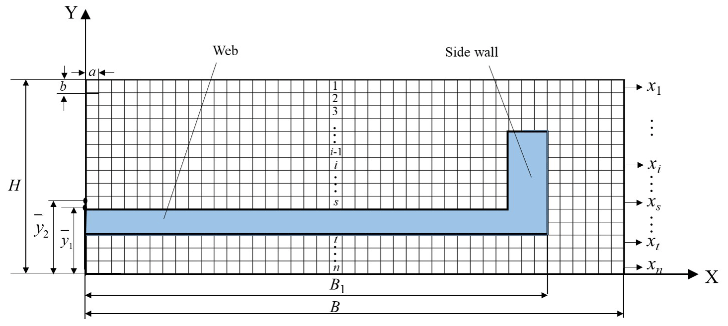
The research object of this paper is the long beam part of identical section and its left–right symmetric structure; the optimization design of the transition structure can be optimized only for half of the cross-section, which will significantly improve the computational efficiency. As shown in Fig. 3, the cross-section of the blank structure is discretized into several units, and the length and width of each unit are set as a and b, respectively. The blue area in the figure shows the area where the final part is located. The total number of units contained in the transition structure needs to be nominated before optimization, and its ratio to the total number of units in the section is the volume retention ratio. The cross-section along the thickness of the blank is divided into n layers. Since the initial residual stress of the blank is distributed along the thickness direction, the initial residual stress contained in each cell in the same layer contributes equally to the machining distortion. In the transition structure, the number of units finally retained in layer i is defined as xi.
For the final part, its expected distortion wfinal can be calculated according to Eq. (1). For the distortion of the transition structure in the optimization model, the detailed derivation process is as follows.
The distance between the centre of the transition structure and the bottom surface can be expressed as follows:
where Ai is the area where the ith cell is located.


The bending moment of the transition structure section can be expressed as the algebraic sum of the equivalent residual stresses in all units over the neutral axis moment.
where σeq is the equivalent residual stress distribution along the thickness of the blank.
The moment of inertia of the transitional structure section can be expressed as the algebraic sum of the quadratic product of the area of each unit and the distance from each unit to the neutral axis.
Combining Eqs. (2), (4) and (5), the distortion of the transition structure wtransitioncan be solved. Based on the above analysis, the optimization model can be described as
where and N1 is the total number of disposable units remaining, based on the volume removal ratio. Considering the actual machining situation, in the area below the web, the entire layer is set to be retained or removed during optimization design. Therefore, in the area below the web(, xi=0 or B1, while in the area above the web(1, is set to avoid units that are half overhanging and observe the units below. In addition, in order to prevent “empty” units in the optimized section profile, it is necessary to manually set all units in each layer to be contiguous, and the right side is adjacent to the final-part sidewall. Besides, ui is the upper bound of xi and li is the lower bound of xi.

3.3 Algorithm flow
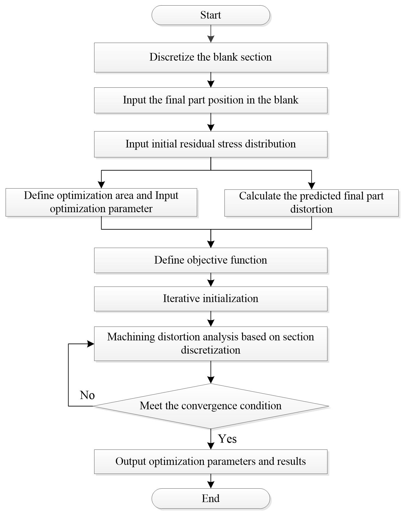
Figure 4 depicts the algorithm flow proposed in this paper. The following are the steps in the entire method:
-
The blank section is created and divided into several equally sized units. The position of the part in the blank is entered, and the initial residual stress distribution curve inside the blank is introduced.
-
The predicted final-part distortion is calculated using the machining distortion analysis model proposed in this research. At the same time, the optimal design region is defined and relevant parameters are given.
-
Establish the optimization model for the transition structure, define the objective function, perform a distortion analysis of the structure and calculate the initial objective function value.
-
The iteration process begins. If the objective goal is achieved, the optimization is terminated and the iteration history and optimization result are output; otherwise the optimization is iterated again.
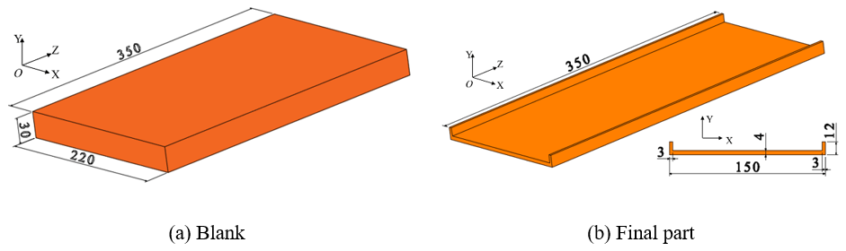
4.1 The part geometry
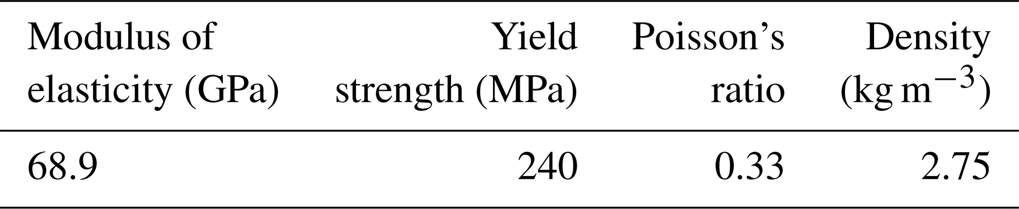
A simplified U-shaped beam part is built as illustrated in Fig. 5 to validate the proposed method in this study. The blank is a pre-stretched aluminium alloy plate made from AA6061-T651, and the part dimensions are shown in Fig. 5. The material properties are listed in Table 1 (Fan et al., 2021).
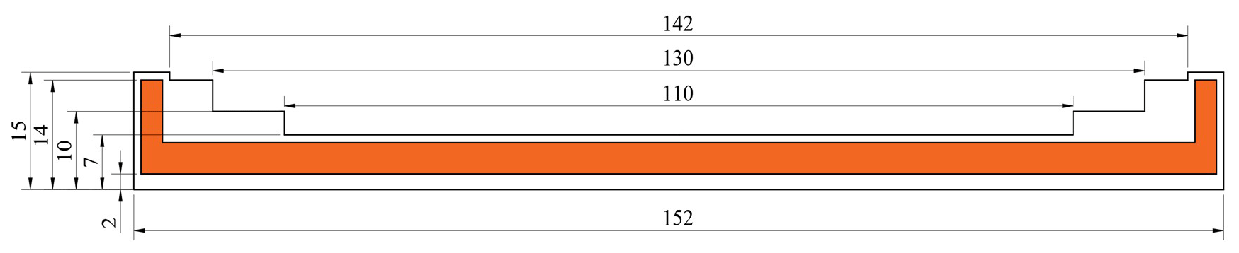
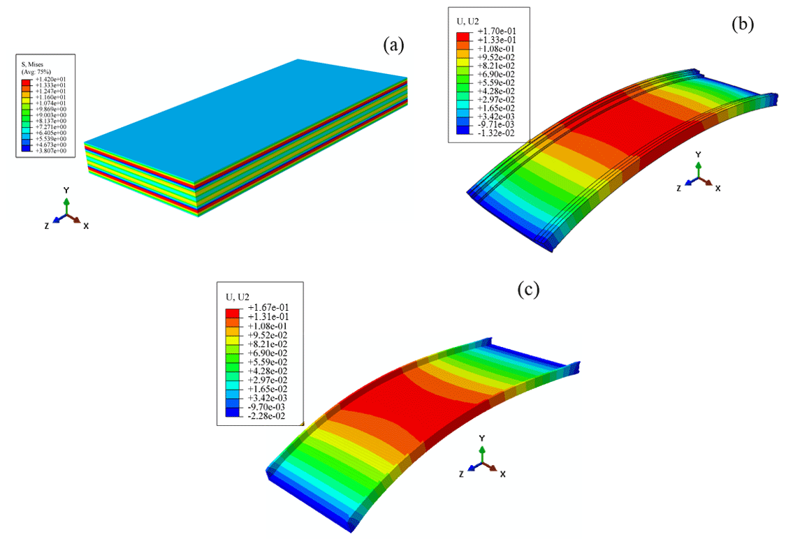
Figure 11The FEM process. (a) The FE model of the blank. (b) The simulation results of the transition structure. (c) The simulation results of the final part.
The crack compliance method (Yang et al., 2019) was used to determine the initial residual stress distribution. As is shown in Fig. 6, an electrode made of 0.18 mm molybdenum wire was used for crack making, and the specimen was cut 1 mm along the thickness direction each time. A KD7016 static strain gauge with a precision of was chosen for strain measurement, and the corresponding strain was recorded. Figure 7 depicts the calculated equivalent residual stress distribution along the thickness direction of the blank. The equivalent residual stress takes into account the effect of transverse stress on bending distortion (Ye et al., 2020). It is used in the topology optimization model and the finite-element simulation that follows.
Table 2Comparison of maximum distortion values of the transition structure and final part.

4.2 Optimization of the transition structure
As shown in Fig. 8, half of the blank cross-section was selected for optimization. The position of the bottom surface of the part with respect to the bottom surface of the blank was set to be 8 mm. At this point, the predicted distortion of the final part is −0.1782 mm. The entire blank cross-sectional area is discretely divided into rectangular units, each with a size of 1 mm × 1 mm. In traditional machining process design, the allowance after rough machining is generally selected as 2 mm in the thickness and height direction (Yang et al., 2019). Based on this, a volume retention ratio of 20 % was chosen for this study.
Based on actual machining conditions, at least one layer of units must be retained around the final part after rough machining. This part of the units, like the final part, belongs to the frozen area during optimization. After removing the units in the frozen area, a total of 164 units were used as optimization objects. Based on the actual machining, the diagonal area in the figure is selected as the design area. Based on the limit of the total number of optimization units and combined with the part structure, the optimization model of this part can be expressed as follows:
Here, the initial value of optimization is taken as x1=0, x2=11, x3=11, x4=11, x5=11, x6=11, x7=11, x8=11, x9=11 and x10=76. The optimization calculation process was performed using MATLAB 2022b software.
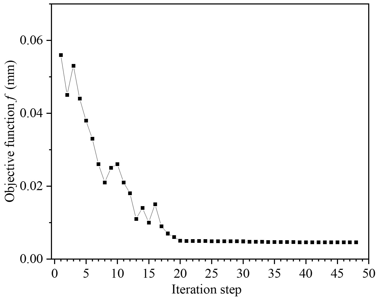
The optimization iteration process is shown in Fig. 9, and the objective function f decreases as the number of iterations increases. After 48 iterations, the algorithm converges. The minimum value of the objective function f is 0.0046 mm, and the corresponding distortion of the transition structure wtransition is −0.1737 mm. The optimal solution is x1=0, x2=6, x3=6, x4=6, x5=6, x6=16, x7=16, x8=16, x9=16 and x10=1. The shape of the transition structure corresponding to the optimal solution is shown in Fig. 10.
4.3 Finite-element simulation verification
The ABAQUS software was used to validate the proposed methodology through finite-element method (FEM). The simulation model's material characteristics were defined in accordance with Table 1. In the simulation, the material's properties were set to be homogeneous and isotropic. The “birth and death” method was used to remove material in FEM (Su et al., 2013; Arrazola et al., 2013). C3D8R is used to mesh the blank, which has 19 358 cells and 386 626 nodes. The boundary condition, which constrained the workpiece's rigid motion, was adopted as the 3–2–1 constraint condition. The corresponding initial residual stresses were loaded into the finite-element model. The transition structure's simulation results are displayed in Fig. 11b, while the final part's simulation results are displayed in Fig. 11c. It can be seen from Fig. 10a that the initial residual stress added to the blank is uniformly distributed along the thickness direction, and the distortion trend of the transition structure and the final part is completely consistent. According to the simulation results, the transition structure's distortion value is −0.17 mm. Likewise, the final-part distortion value is −0.167 mm. For the final distortion of the part and the distortion value of the transition structure, the simulation results are highly consistent with the theoretical calculation values, with relative errors of 4.6 % and 3.8 %, respectively.
4.4 Machining test
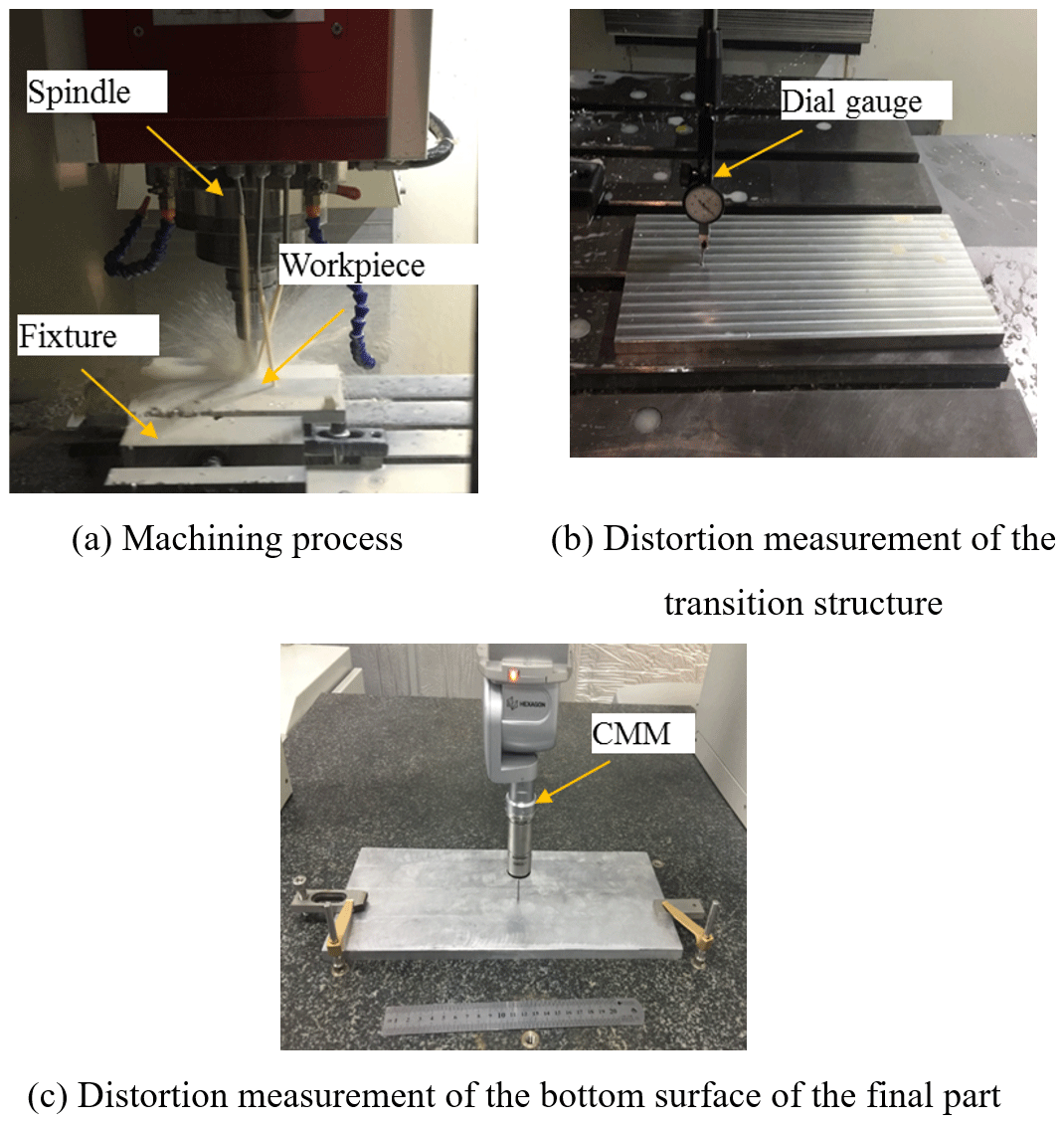
For further verification, machining experiments were carried out. The experiments were carried out on a VC-3016G high-speed vertical milling machine. A three-tooth carbide end mill with a diameter of 12 mm was used for the machining experiment. The machining was carried out at high speed with a spindle speed of 18 000 rpm, a feed of 7000 mm min−1 and a depth of cut of 2 mm. The machining process was cooled by cutting fluid to minimize the effect of cutting heat on the machining distortion. The clamping method is vise clamping. The machining process is shown in Fig. 12a. The corresponding transition structure was machined in the experiment, and the maximum distortion of the transition structure of the part was measured using a micrometer, as shown in Fig. 12b.
The part was re-clamped after the distortion of the transition structure was measured, and it was then machined to the final-part shape. To verify the validity of the experimental results, the machining tests were conducted three times with identical clamping settings and cutting parameters for each cut. The final distortion is determined as the average of the measured values after three machining operations.
A MISTRAL coordinate measuring machine (CMM) with 0.005 mm precision was used to measure the final part's contour. As indicated in Fig. 12c, distortion is measured every 5 mm along the midline of the part's bottom.
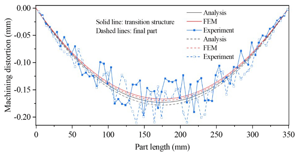
The experimental distortion is compared to the finite-element simulation and theoretical calculations in Fig. 13. The distortion curves of the parts from theoretical analysis and finite-element simulation are approximately smooth, as shown in the figure. The largest distortion is found at 175 mm in the midpoint of the theoretical analysis and finite-element simulation results. It can be seen that the finite-element simulation value is highly consistent with the theoretical calculation value. The distortion value and distribution of the actual experimental measurement value are in good agreement when compared to the first two; however, there is a little deviation at each measurement point. The comparison of maximum distortion values of the transition structure and final part is shown in Table 2. The maximum experimental distortion values of the transition structure and final part are −0.20 and −0.21 mm, respectively. The maximum distortion value of the experiment is slightly larger than the theoretical calculation value and simulation value. The transition structure and final part have acceptable maximum relative errors of 24.6 % and 23.1 %, respectively, between theoretical calculation results and experimental results. Error generation is primarily caused by three factors (Ye et al., 2020; Weber et al., 2022; Huang et al., 2022): (1) the residual stress brought on by machining is not considered; (2) the effects of clamping and cutting load on machining distortion are not considered; (3) a measurement error. The results of residual stress measurements and CMM measurements are influenced by the instrument's accuracy.
The optimization of the transition structure of long beam parts is investigated in this study, which provides a new approach for the study of machining distortion control of aeronautic monolithic components. The following are some of the conclusions that can be drawn.
-
An initial residual stress-based analytical model for machining distortion of long beam parts with identical cross-sections is established. The idea of controlling the machining distortion of long beam parts by optimizing the workpiece structure before the start of the finishing stage, i.e. the transition structure, is proposed.
-
An optimization model for the cross-section of the transition structure is developed, using the minimum difference between the expected distortion of the transition structure and the final part as the design goal.
-
For verification, a simplified U-shaped beam is utilized. The theoretical maximum distortion of the optimized transition structure and the final part is −0.174 and −0.1782 mm, respectively, with a relative error of 2.9 %. The transition structure and final part have acceptable maximum relative errors of 24.6 % and 23.1 %, respectively, between theoretical calculation results and experimental results. The results of machining experiments and finite-element simulation demonstrate the correctness of the proposed model.
The datasets generated during and/or analysed for the current study are available from the corresponding author on reasonable request.
L-XF: methodology, data collection and writing (original draft); NH: data collection and writing (reviewing); YZ: conceptualization, investigation and editing.
The contact author has declared that none of the authors has any competing interests.
Publisher’s note: Copernicus Publications remains neutral with regard to jurisdictional claims made in the text, published maps, institutional affiliations, or any other geographical representation in this paper. While Copernicus Publications makes every effort to include appropriate place names, the final responsibility lies with the authors.
This paper was edited by Xichun Luo and reviewed by three anonymous referees.
Akhtar, W., Ismail L., and Steven, Y. L.: Prediction and control of residual stress-based distortions in the machining of aerospace parts: A review, J. Manuf. Process., 76, 106–122, https://doi.org/10.1016/j.jmapro.2022.02.005, 2022.
Arrazola, P. J., Özel, T., Umbrello, D., Davies, M., and Jawahir, I. S: Recent advances in modelling of metal machining processes, Cirp Annals, 62, 695–718, https://doi.org/10.1016/j.cirp.2013.05.006, 2013.
Brinksmeier, E., Cammett, J. T., König, W., Leskovar, P., Peters, J., and Tönshoff, H. K.: Residual stresses – measurement and causes in machining processes, CIRP annals, 31, 491–510, https://doi.org/10.1016/S0007-8506(07)60172-3, 1982.
Casuso, M., Polvorosa, R., Veiga, F., Suárez, A., and Lamikiz, A.: Residual stress and distortion modeling on aeronautical aluminum alloy parts for machining sequence optimization, Int. J. Adv. Manuf. Tech., 110, 1219–1232, https://doi.org/10.1007/s00170-020-05816-7, 2020.
Fan, L., Tian, H., Li, L., Yang, Y., Zhou, N., and He, N. Machining distortion minimization of monolithic aircraft parts based on the energy principle, Metals, 10, 1586–1592, https://doi.org/10.3390/met10121586, 2020.
Fan, L., Li, L., Yang, Y., Zhao, G., Han, N., Tian, H., and He, N.: Control of machining distortion stability in machining of monolithic aircraft parts, Int. J. Adv. Manuf. Tech., 112, 3189–3199, https://doi.org/10.1007/s00170-021-06605-6, 2021.
Fan, L. X., Han, N., Li, L., He, N., Liu, E. L., and Yang, Y. F.: Prediction of Machining Distortion of Long Beam Monolithic Components Based on the Energy Principle, Integrat. Ferroelect., 233, 97–109, https://doi.org/10.1080/10584587.2023.2191517, 2023.
Gao, H. J., Li, X., Wu, Q., Lin, M. H., and Zhang, Y. D.: Effects of residual stress and equivalent bending stiffness on the dimensional stability of the thin-walled parts, Int. J. Adv. Manuf. Tech., 119, 4907–4924, https://doi.org/10.1007/s00170-021-08252-3, 2022.
Huang, X., Liu, X., Li, J., Chen, Y., Wei, D., and Ding, G.: Machining deformation analysis of aircraft monolithic components based on the energy method, Int. J. Adv. Manuf. Tech., 119, 5797–5805, https://doi.org/10.1007/s00170-021-08531-z, 2022.
Li, B., Jiang, X., Yang, J., and Liang, S. Y.: Effects of depth of cut on the redistribution of residual stress and distortion during the milling of thin-walled part, J. Mater. Process. Tech., 216, 223–233, https://doi.org/10.1016/j.jmatprotec.2014.09.016, 2015.
Liu, L., Sun, J., Chen, W., and Zhang, J.: Finite element analysis of machining processes of turbine disk of Inconel 718 high-temperature wrought alloy based on the theorem of minimum potential energy, Int. J. Adv. Manuf. Tech., 88, 3357–3369, https://doi.org/10.1007/s00170-016-9026-1, 2017.
Richter-Trummer, V., Koch, D., Witte, A., Dos Santos, J. F., and De Castro, P. M. S. T.: Methodology for prediction of distortion of workpieces manufactured by high speed machining based on an accurate through-the-thickness residual stress determination, Int. J. Adv. Manuf. Tech., 68, 2271–2281, https://doi.org/10.1007/s00170-013-4828-x, 2013.
Robinson, J. S., Tanner, D. A., Truman, C. E., and Wimpory, R. C.: Measurement and prediction of machining induced redistribution of residual stress in the aluminium alloy 7449, Exp. Mech., 51, 981–993, https://doi.org/10.1007/s11340-010-9389-4, 2011.
Su, J. C., Young, K. A., Ma, K., Srivatsa, S., Morehouse, J. B., and Liang, S. Y.: Modeling of residual stresses in milling, Int. J. Adv. Manuf. Tech., 65, 717–733, https://doi.org/10.1007/s00170-012-4211-3, 2013.
Wang, S. Q., He, C. L., and Cao, Z. M.: Machining distortion in the milling of multi-frame components, J. Manuf. Process., 68, 1158–1175, https://doi.org/10.1016/j.jmapro.2021.06.024, 2021.
Wang, Z., Sun, J., Liu, L., Wang, R., and Chen, W.: An analytical model to predict the machining deformation of frame parts caused by residual stress, J. Mat. Process. Tech., 274, 116282, https://doi.org/10.1016/j.jmatprotec.2019.116282, 2019.
Weber, D., Kirsch, B., Jonsson, J. E., D'Elia, C. R., Linke, B. S., Hill, M. R., and Aurich, J. C.: Simulation based compensation techniques to minimize distortion of thin-walled monolithic aluminum parts due to residual stresses, CIRP J. Manuf. Sci. Tech., 38, 427–441, https://doi.org/10.1016/j.cirpj.2022.05.016, 2022.
Yang, Y., Li, X., Li, L., He, N., Zhao, G., Chen, N., and Zhou, Z.: Investigation on deformation of single-sided stringer parts based on fluctuant initial residual stress, J. Mater. Process. Tech., 271, 623–633, https://doi.org/10.1016/j.jmatprotec, 2019.
Yang, Y., Fan, L., Li, L., Zhao, G., Han, N., Li, X., and He, N.: Energy principle and material removal sequence optimization method in machining of aircraft monolithic parts, Chinese J. Aeronaut., 33, 2770–2781, https://doi.org/10.1016/j.cja.2020.05.018, 2020.
Ye, H., Qin, G., Wang, H., Zuo, D., and Han, X.: A machining position optimization approach to workpiece deformation control for aeronautical monolithic components, Int. J. Adv. Manuf. Tech., 109, 299–313, https://doi.org/10.1007/s00170-020-05588-0, 2020.