the Creative Commons Attribution 4.0 License.
the Creative Commons Attribution 4.0 License.
 | 21 Nov 2023
Structural design and jumping motion planning of the jumping leg inspired by a goat's hindlimb
Longxin He
Zhihan Zhao
Yuwang Lu
Jiajun Tu
Xiangying Ren
Hanzhi Lv
At present, research on bionic jumping robots mainly focuses on imitating various jumping animals, such as kangaroos, frogs, or locusts. These bionic objects have good jumping ability. The goat, as one of these with a moderate size and a strong jumping ability, is very suitable as a prototype to imitate jumping. In this study, first, a simplified serial joint model that imitates a goat's hindlimb is proposed with a comparison analysis of its physiological structure. Then, a jumping leg mechanism that imitates a goat's hindlimb was designed. Second, the kinematics of the goat-inspired jumping leg were constructed to describe the relationship between joint angles and foot positions. Additionally, we used a cubic polynomial to plan the trajectory of the jumping process to achieve a smooth jumping movement based on the characteristics of the goat's jumping, with position and speed constraints during the jump. Thus, we established a smooth jumping trajectory model of the goat-inspired jumping leg. Finally, experiments on the jumping of the goat-inspired jumping leg were conducted. The goat-inspired jumping leg has good jumping performance. In this study, we took the goat's hindlimbs as the bionic model, proposed the goat-inspired jumping leg mechanism, and presented the jumping trajectory planning theory for smooth jumping of the goat-inspired jumping leg. These provide new ideas for the study of bionic jumping legs and can effectively promote further development of bionic jumping robots.
- Article
(4243 KB) - Full-text XML
- BibTeX
- EndNote


Research on jumping robots can be traced back to the 1980s. Raibert and his robot research team first developed the single-legged jumping robot: 3D hopper. The structure has a certain jumping ability, but the structure is complicated and the weight is heavy (Zhou and Bi, 2012). Dokht also made a vertical robot driven by motors, McGill Hopper, in 1993. A spring and screw transmission mechanism was used on its jumping leg to achieve the passive bounce. However, its energy consumption is relatively high and the control is more complex. Since then, Gregorio et al. (1997) improved their control algorithm and developed first- and second-generation jumping legs, ARL-Monpod, based on McGill Hopper (Gregorio et al., 1997). Compared with the previous jumping legs, the energy-saving efficiency is effectively improved. However, its hip structure is large, and its installation on the robot body is difficult.
Nowadays, the research degree of many bionic robots is very high. For example, many underwater bionic robots can operate in a certain environment (Chen et al., 2022b, 2023a, b). At present, the main imitation objects of bionic jumping legs are goats, frogs, kangaroos, or locusts, among which frogs and locusts are difficult to imitate on the basis of their jumping due to their small sizes (Liu et al., 2014; Li et al., 2012; Fan et al., 2022). The locust jumping robot studied (Nguyen and Park, 2012; Chen et al., 2011) has also realized jumping ability, but it is difficult to realize bionic jumping as good as a real locust's due to its small size. Compared with other small jumping animals, the size of a goat is moderate, which greatly reduces the difficulty of imitation. Meanwhile, the approximate size structure can be used to simulate and give its jumping performance more effectively. In addition, goats have excellent jumping abilities. Thus, goats with moderate sizes and good jumping abilities are a good prototype for imitation.
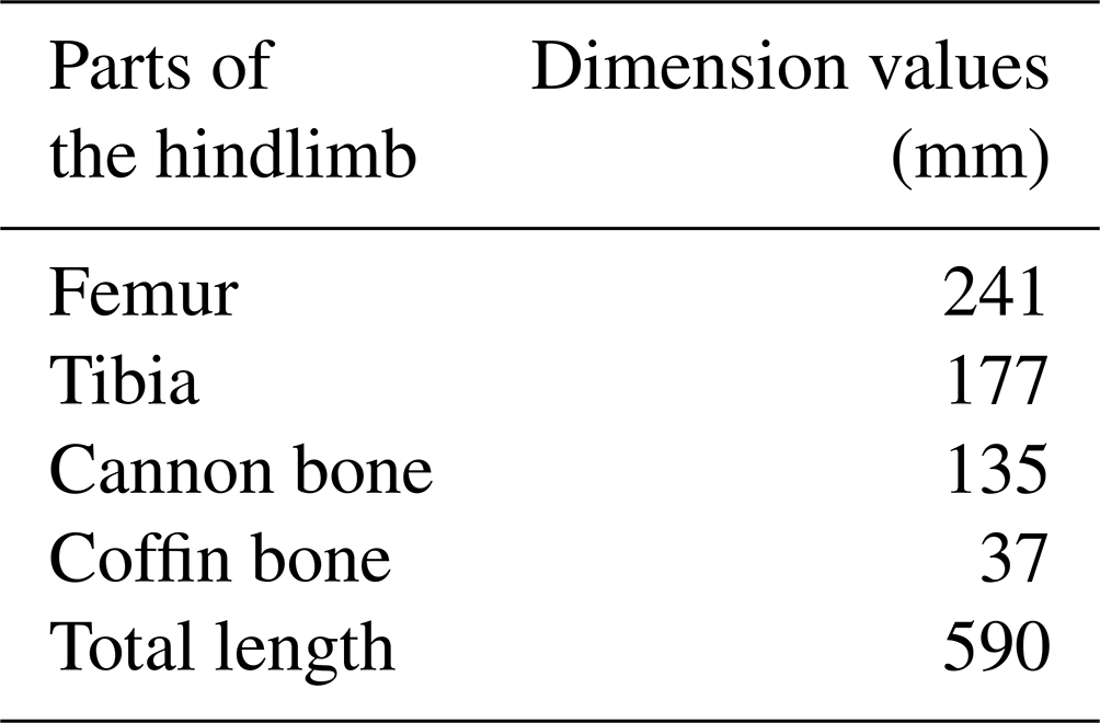
Table 1Structural dimension parameters of the goat-inspired jumping leg inspired by a goat's hindlimb.
Therefore, we took the goat as the bionic research object. First, a jumping leg mechanism that imitates the goat's hindlimb is proposed. Second, the kinematics of the goat-inspired jumping leg is analyzed and the jumping trajectory planning is conducted with cubic polynomial curves to guarantee its smoothness in the jumping process. Finally, experiments on the jumping of the goat-inspired jumping leg are conducted to test its jumping performance and to verify the correctness of the kinematic model and jumping trajectory planning method of the leg.
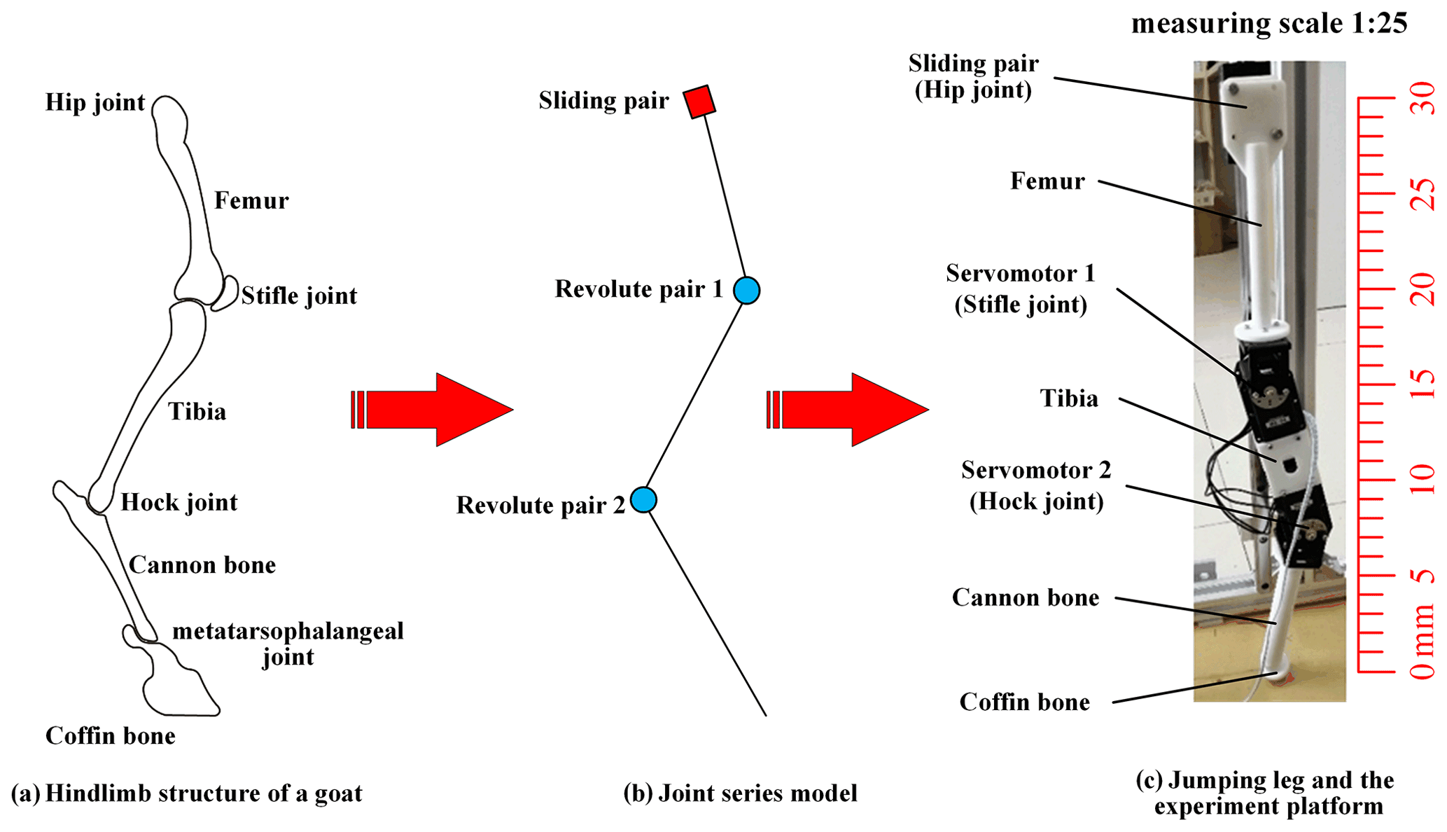
David V. Lee and Polly McGuigan explored the actuation (Lee et al., 2006), compliance, and work characteristics of three adult female goats, which are African dwarf breeds, by analyzing their characteristics of the forelimb and hindlimb. On this basis, we established the series joint model to simulate the goat-inspired jumping leg and designed the hindlimb jumping mechanism. In detail, through the study and analysis of the physiological characteristics of a goat's hindlimb, the hindlimb structure of a goat's leg was obtained, the overall degree of freedom of the mechanism was analyzed, and the distribution of each joint was carried out to develop the overall scheme of the goat-inspired jumping leg. According to the established scheme, the structure of the goat-inspired jumping leg was designed, and 3D modeling was carried out. Meanwhile, the mechanical analysis and strength check of the goat-inspired jumping leg structure were carried out. Finally, the test prototype was manufactured and assembled. Figure 1a shows the skeleton of a goat's hindlimb. It contains four main joints: the hip joint, the stifle joint, the hock joint, and the metatarsophalangeal joint. In this study, three joints of the goat's hindlimb are mainly imitated as shown in Fig. 1b. The first one is the hip joint, which is replaced by a sliding pair in the design. The joint uses a slider guide mechanism to achieve the jump-up function. Two servomotors are used in the design as the revolute pair to imitate the stifle joint and the hock joint (Fig. 1c). In the study, the coordinated motion of the two servomotors is the key to implementing the leg's jumping. Each structure of the legs was 3D-printed using photosensitive resin. In addition, the spherical foot is adopted instead of the metatarsal to simplify the jumping leg model and control (İlgen et al., 2016; Wang and Cong, 2014). The dimension parameters of the goat-inspired jumping leg structure model inspired by the goat hindlimb structure are shown in Table 1.
3.1 Coordinate system of the goat-inspired jumping leg
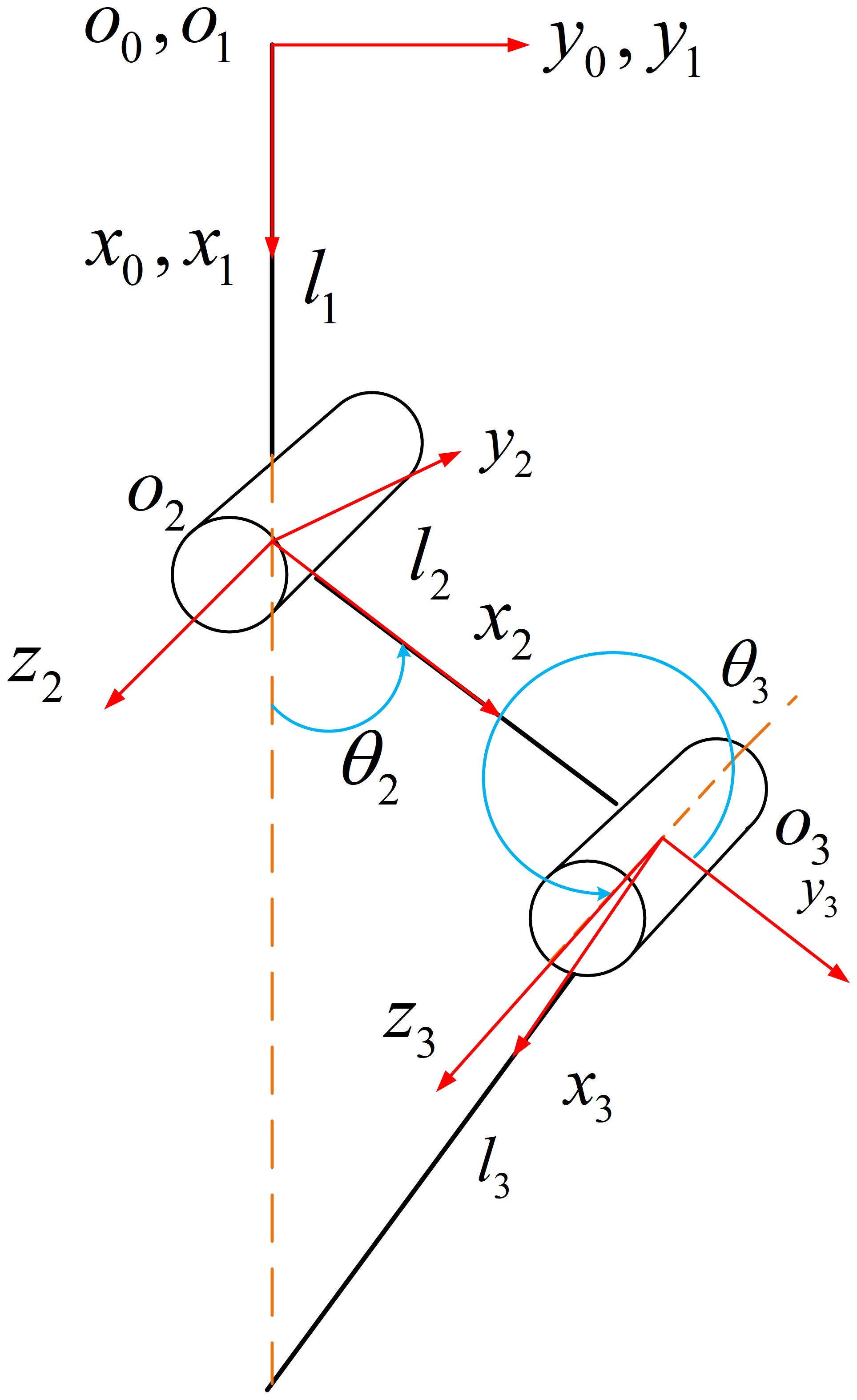
Kinematics analysis is an important method to analyze the robot's motion. In this study, the D–H (Denavit–Hartenberg) parameter method is used to perform the kinematics analysis of the goat-inspired jumping leg. The kinematic coordinate system of the goat-inspired jumping leg is shown in Fig. 2. The D–H parameter method is currently the basic method for studying the robot kinematics (Wang et al., 2020), which can perfectly describe the position and posture relationship of each joint of the robot. Thus, we use the D–H method to establish the kinematic equation of the goat-inspired jumping leg.
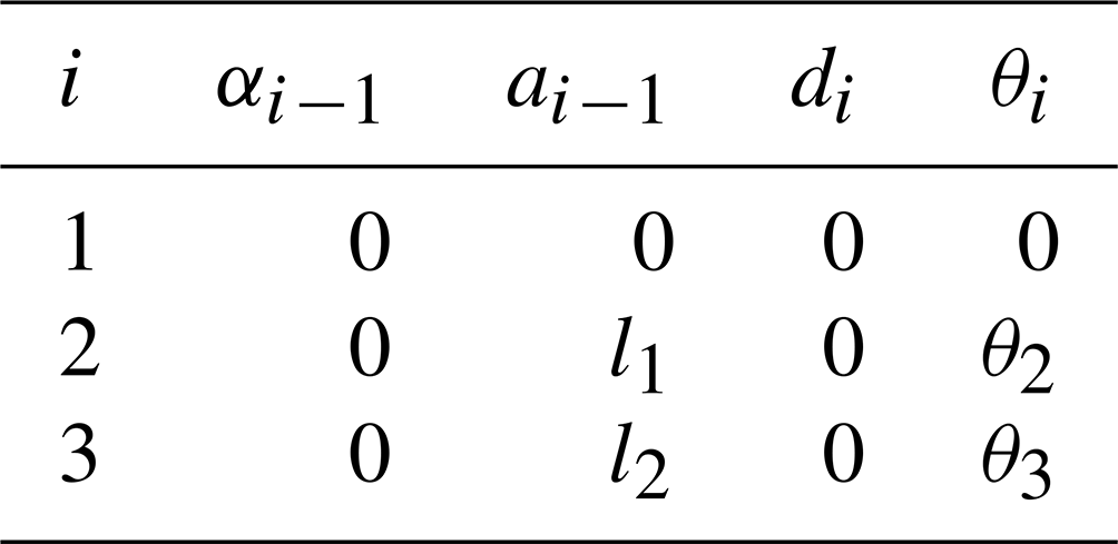
In the coordinate system of the goat-inspired jumping leg, the joint axes of the goat-inspired jumping leg are parallel to each other (Chen et al., 2022a; Ma et al., 2019). The z axis is defined along the joint axis and the x axis is set along the linkage. Therefore, the D–H parameters of the goat-inspired jumping leg can be obtained and are shown in Table 2 according to the principle of D–H parameters.
3.2 Forward kinematics of the goat-inspired jumping leg
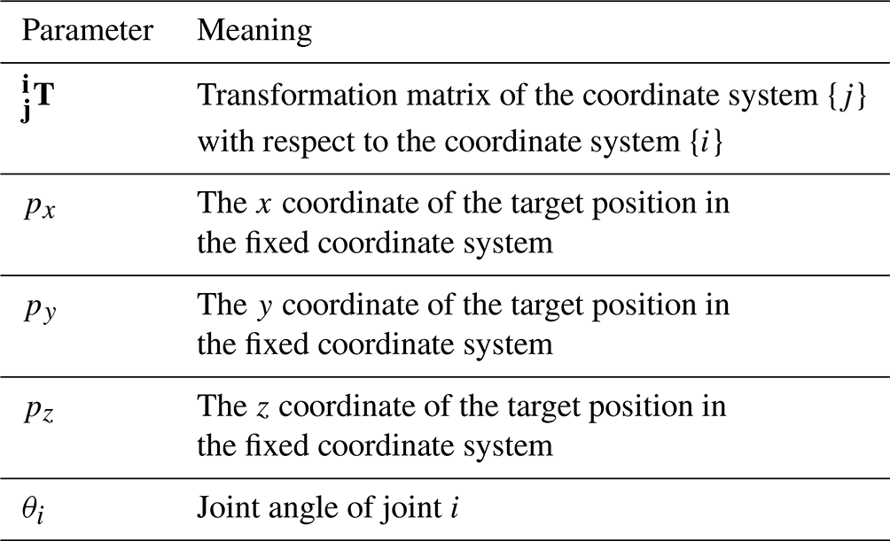
The parameters of the forward kinematics can be obtained and are shown in Table 3. According to the kinematics theory, the general form of the coordinate system transformation between the connected links can be derived, and these independent transformations can be multiplied in sequence to obtain the pose matrix of the end of the goat-inspired jumping leg relative to the fixed coordinate system, i.e.,
Equations (1) and (2) represent the transformation matrix between the two coordinates where s and c stand for sin and cos, respectively, and αi−1, ai−1, θi, and di are the data in Table 2. Thus, we can get the following.
Among them, is the transformation matrix between the coordinate O0 and the coordinate O1. Similarly, and , respectively, are expressed as the transformation matrix between the coordinate system O1 and O2 and the transformation matrix between the coordinate system O2 and O3. indicates the transformation matrix of the end of the goat-inspired jumping leg relative to the fixed coordinate system O0, i.e.,
where , , s2=sin θ2, and c2=cos θ2.
Equation (7) can be expressed as follows.
In Eq. (8), R is the rotation matrix and is the displacement matrix (Zhou et al., 2008), i.e., the position matrix of the end of the goat-inspired jumping leg relative to the fixed coordinate system O0. They are expressed as follows.
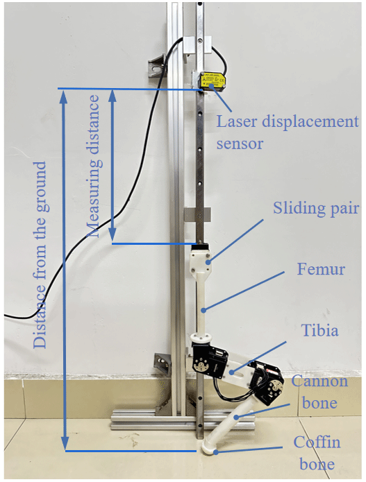
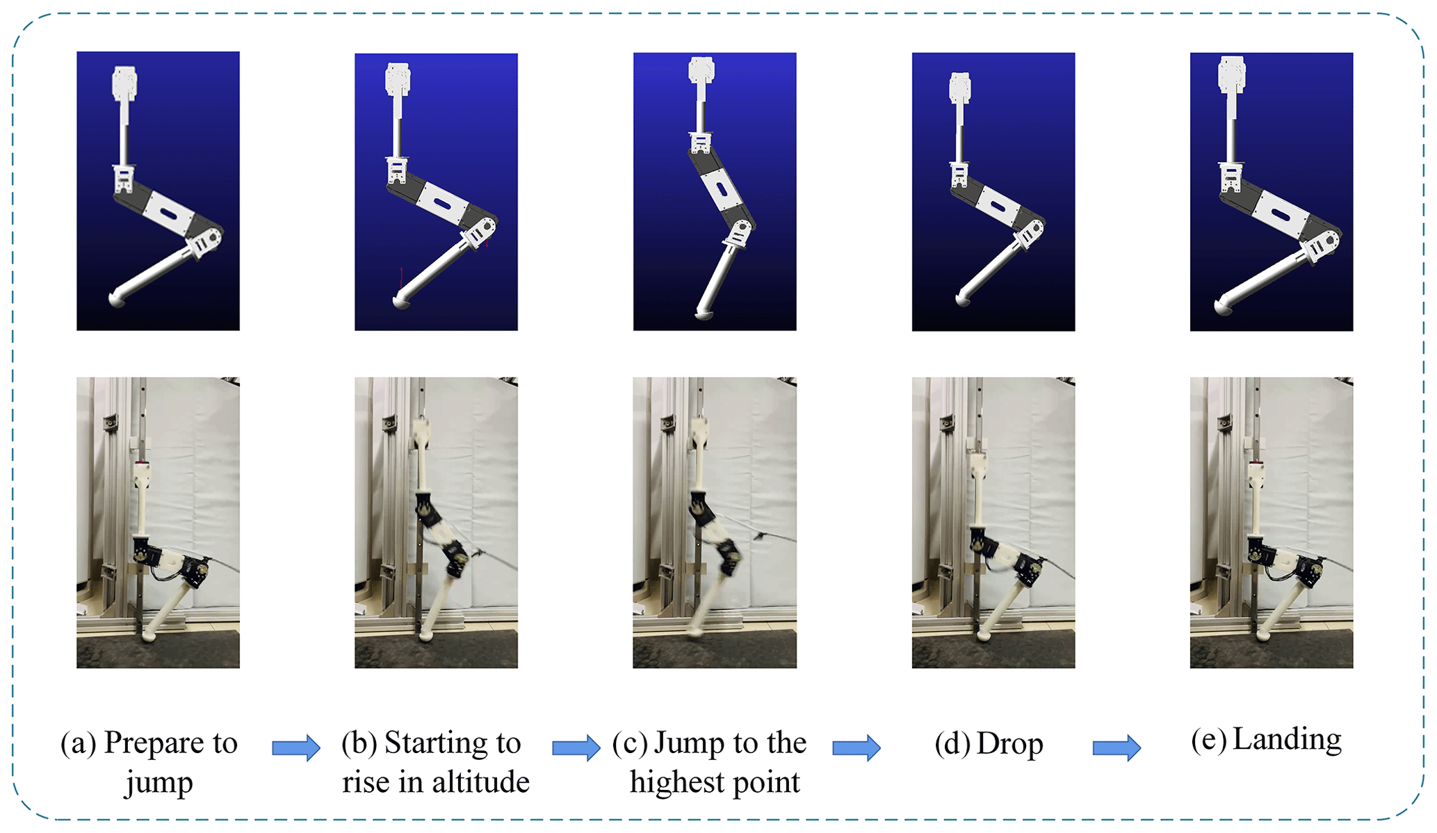
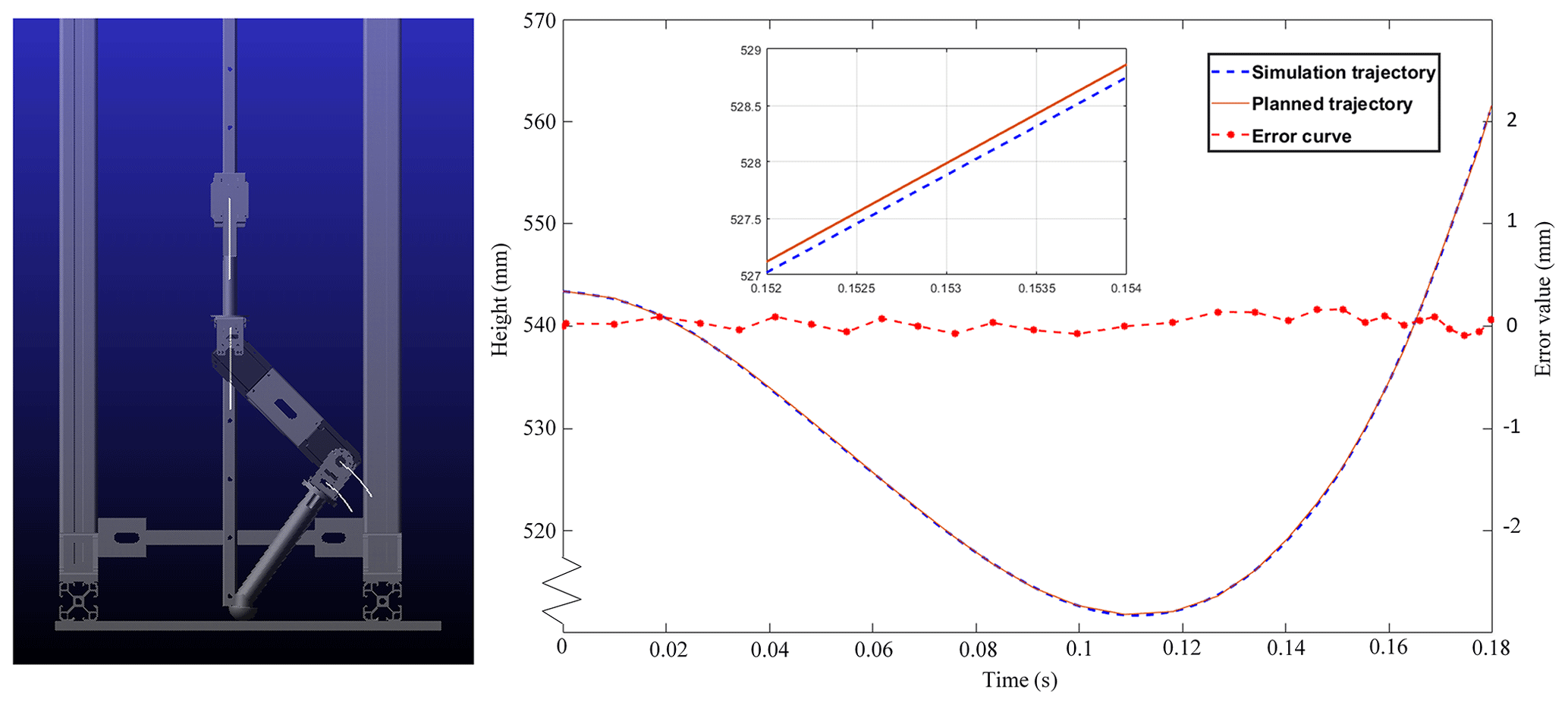
Figure 10The simulated trajectory, the planned trajectory, and the error curve of the goat-inspired jumping leg.
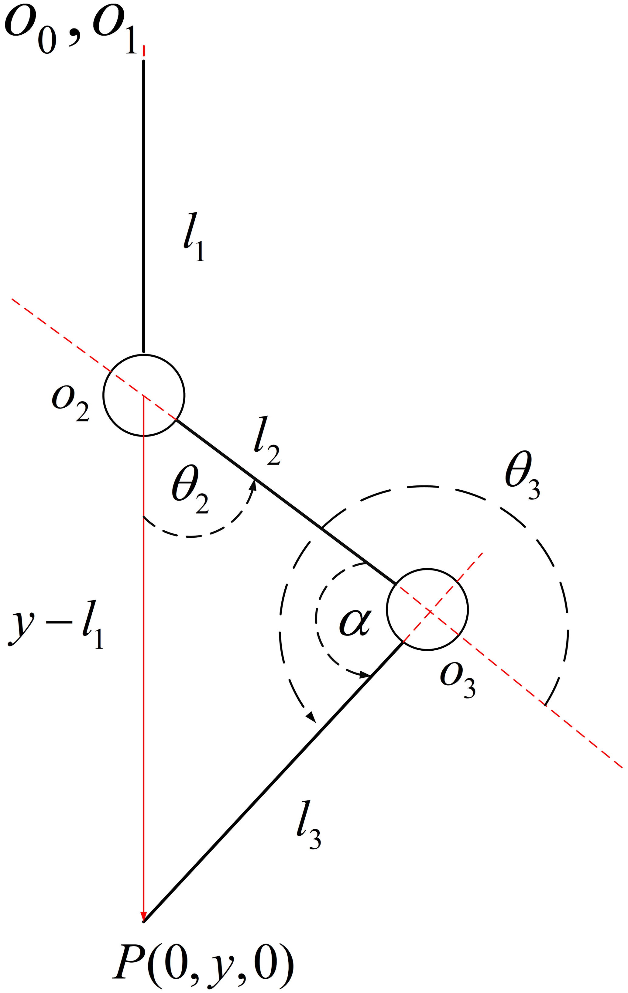
3.3 Inverse kinematics analysis of the goat-inspired jumping leg
Through the inverse kinematics analysis of the goat-inspired jumping leg, the joint angles θ2 and θ3 of the goat-inspired jumping leg can be obtained by knowing the position of the end of the goat-inspired jumping leg in the coordinate system O0. Thus, precise control of the joint angles of the goat-inspired jumping leg can be achieved during the jumping. Here, the geometric solution method of the inverse kinematics is used, and the inverse kinematic model is established as shown in Fig. 3.
According to the geometric relationship in the inverse kinematic model, the geometric relationship between the joint angle θ2 and the angle α is expressed as
Therefore,
The relationship between the joint angle θ3 and α is calculated as
Kinematics analysis is an important method to analyze the robot motion. Through kinematics analysis, the position and attitude relationship of each joint can be described well, so that the angle of the joint of the goat-inspired jumping leg can be accurately controlled during the jumping process, thus laying the foundation for the subsequent trajectory planning of the robot.
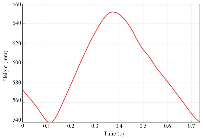
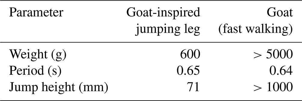
Table 5Comparison of the goat-inspired jumping leg and the goat (fast-walking).
In order to guarantee smoothness in the take-off and landing of the goat-inspired jumping leg and to reduce shocks, the movement trajectory of the goat-inspired jumping leg's hip centroid height with time should be planned (Wang et al., 2016; Zhu et al., 2019; Wang et al., 2018). Based on the structure of the goat-inspired jumping leg and jumping characteristics of the goat leg, this study used a cubic polynomial for robot motion trajectory planning. This method can quickly generate each joint motion trajectory of the robot and obtain smooth motion curves.
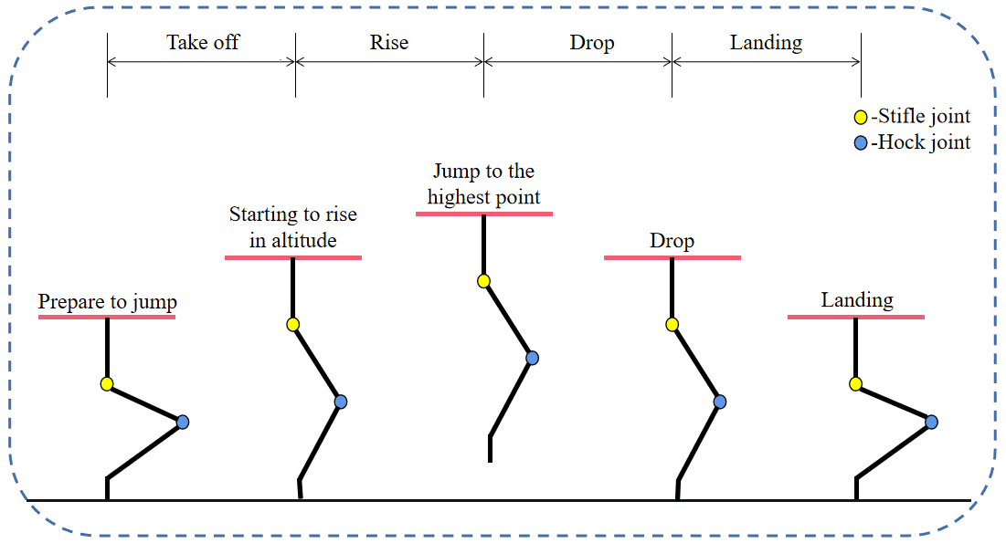
Based on the analysis of the jumping process of goats, we decompose the jumping process and divide it into four stages, i.e., take-off, rise, drop, and landing (Gao and Han, 2018; Luo et al., 2014), which are shown in Fig. 4.
In the take-off stage, the foot end of the goat-inspired jumping leg is in contact with the ground and the center of gravity of the leg rise and prepares for the next stage. When the foot end leaves the ground and the goat-inspired jumping leg is in the rising stage, the goat-inspired jumping leg decelerates and rises at the initial speed v1. When the speed just drops to 0, the goat-inspired jumping leg reaches the highest point in the jumping process, and then the jumping mechanism begins to fall. In the drop stage the leg's velocity increases. When the foot contacts the ground, the landing stage starts, and the goat-inspired jumping leg starts to slow down to 0, where the mechanism is stable and a jump is completed.
According to the analysis of the jump process, the equation of the cubic polynomial can be written as
The speed equation of the goat-inspired jumping leg during the take-off and fall stages is
where Yj(t) is the hip joint centroid height of the goat-inspired jumping leg, kil is the equation coefficient, t is time, and is the hip joint centroid velocity of the goat-inspired jumping leg. ; ; .
The constraints on the position and speed in the take-off stage are as follows.
The constraints on the position and speed in the landing stage are as follows.
H10 is the height of the center of mass of the hip joint when the goat-inspired jumping leg is in the starting position. H11 is the height of the center of mass of the hip joint when the foot of the goat-inspired jumping leg just leaves the ground, and H40 is the height of the center of mass of the hip joint when the foot end just touches the ground. H41 is the height of the center of mass of the hip joint after the jumping mechanism is stable. v1 is the instantaneous velocity of the center of mass of the hip joint when the foot of the goat-inspired jumping leg just leaves the ground.
The cubic polynomial parameters that can be solved according to the given constraints are
and
Therefore, the trajectory of the hip in the take-off stage is
The trajectory of the hip in the landing stage is
After the foot end leaves the ground, the movement of the goat-inspired jumping leg is a free-fall motion, i.e., rising at the initial speed v1 and falling at the initial speed of 0.
Let the time of rising to the highest point be t2.
At this time, the trajectory is
In an ideal situation, the time t2 of the goat-inspired jumping leg that falls from the highest point to the ground is equal to t3. The trajectory of the falling process is expressed as
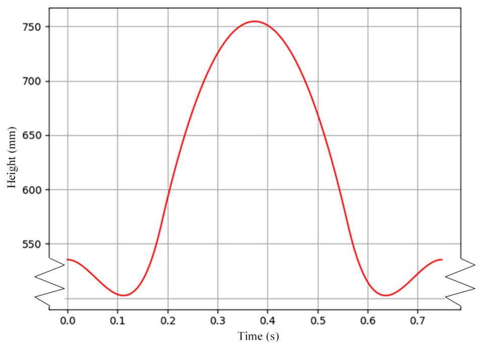
where Hm is the highest point of the center of mass of the hip joint of the goat-inspired jumping leg. Taking v1=1.90 m s−1, H10=535 mm, H11=570 mm, and mm, the trajectory of the goat-inspired jumping leg in the jumping process is depicted in Fig. 5.
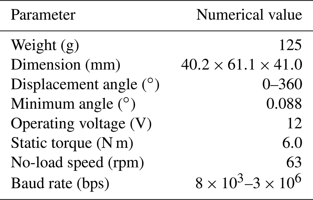
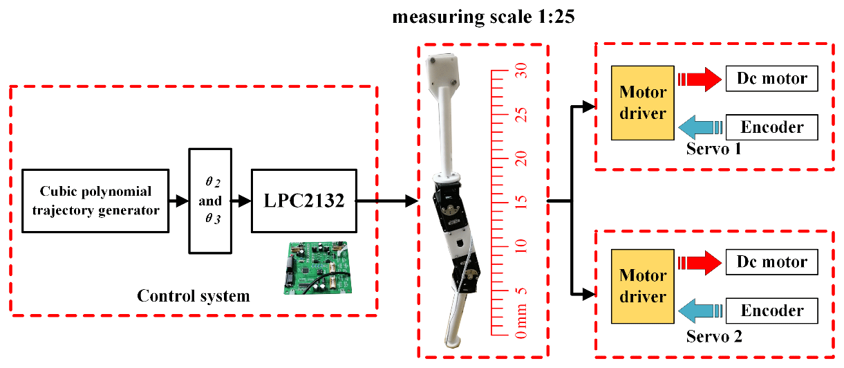
The RX-64 servomotor is chosen and used in the jumping leg mechanism. The minimum angle of the motor is 0.088∘, which has a relatively high control accuracy. The specific parameters of the RX-64 servomotor are shown in Table 4. In the design of the control system (Fig. 6), this mainly includes a cubic polynomial trajectory generator and an LPC2132 chip. Firstly, the whole take-off process is planned to be 0.18 s and is divided into 50 jump time intervals (one jump time interval every 0.0036 s). Secondly, the angle changes in the two joints during the jumping process are analyzed according to the results of the cubic polynomial and the inverse motion trajectory. Finally, a serial port is used to send the joint angles to the servomotors to control the movement of the goat-inspired jumping leg.
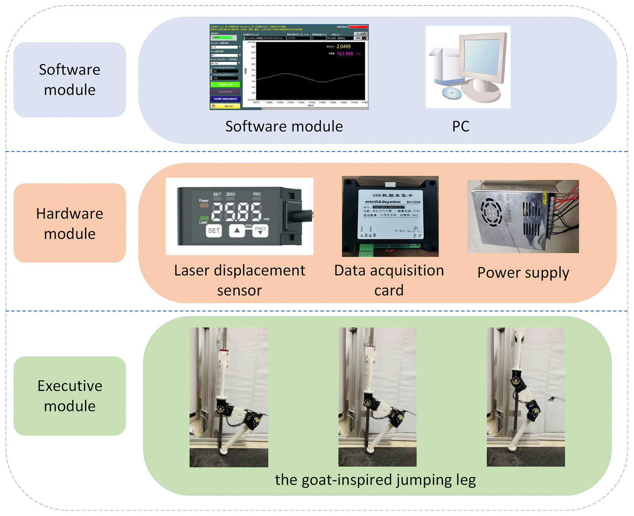
The measurement is important for the experiment. Thus, we selected a laser displacement sensor (HG-C1400), and Fig. 7 describes the measurement system in detail. The laser displacement sensor (HG-C1400) measures at a frequency of 600 Hz and can obtain enough data to record the jumping process in the goat leg jumping experiment. The sensor detected the height of the hip joint from the sensor in real time and collected and processed the data to obtain the height of the hip joint from the ground through conversion. Combined with the height of the hip joint from the ground when the foot of the goat-inspired jumping leg takes off from the ground, the actual jump height of the goat-inspired jumping leg is calculated. The experimental platform is shown in Fig. 8.
In the jumping experiment, we can see that the leg moves quickly to the initial position (Fig. 9a), starts to take off (Fig. 9b), continues to rise to the highest point (Fig. 9c), begins to fall (Fig. 9d), and then returns to the original position and prepares for the next jumping cycle (Fig. 9e). Figure 10 is a schematic diagram of the simulation trajectory, planned trajectory, and error curve of the goat-inspired jumping leg in the take-off stage, where the blue dashed line is the simulation trajectory and the red solid line is the planned trajectory.
According to the data measured in the experiment, the relationship between the jumping height and the jumping time during the experiment was plotted (Fig. 11). It can be seen from the experimental results that the goat-inspired jumping leg has a good jumping ability and basically completes the preliminary goal set by the experiment. This provides some experience for future research on jumping robots and provides a foundation for further research in the future. Table 5 shows a comparison of parameters of jumping legs of the goat-inspired jumping leg and the goat's leg (fast-walking). According to Table 5 and Fig. 11, the movement cycle of the goat-inspired jumping leg is similar to that of goats (fast-walking). The metatarsal plays an extremely important role in shock prevention and stability in the running and jumping processes of goats. In the experiment, the spherical foot is used to replace the metatarsal. Therefore, in the experiment, a certain impact phenomenon exists in the movement of the goat-inspired jumping leg, which has a certain impact on the jumping height. By comparing the theoretical and experimental results, it can be found that there is a certain gap between the actual jump height (71 mm) and the theoretical jump height (152 mm) of the jumping leg. It is speculated that the main reasons for this result are the following. (1) The experimental prototype lacks an accumulator, and the jumping explosive force is limited. (2) There is a certain friction between the slide rail and the slide block, which consumes part of the jumping energy. (3) There is divergence of foot force during actual takeoff, which weakens the effectiveness of takeoff to a certain extent. (4) Lacking a metatarsal, the impact during the experiment has an influence on jumping.
Goats' excellent walking ability and jumping ability in complex environments are the reasons why we chose them as bionic objects. First, we design a mechanical mechanism of a jumping leg according to the physiological structure and movement mechanism of a goat's hindlimbs. Second, the designed jumping mechanism is kinematically analyzed by using the D–H parameter method to study the relationship between the positions of the goat-inspired jumping leg and the joint angles during the jumping. In addition, the jumping process is divided according to the goat's jumping mechanism. On this basis, cubic polynomial curves are used to plan their trajectories to realize stability and avoid impacts during jumping and landing. Finally, a platform is designed for jumping experiments. The goat-inspired jumping leg has a relatively good jumping ability and basically completes the initial goal set by the experiment. The goat-inspired jumping leg inspired by the goat's hindlimb has a good jumping performance. The bionic mechanism and the jumping theory of the proposed jumping leg can be used as references for future bionic jumping studies and can promote the development of bionic jumping robots.
In future work, we will improve the structure of the leg and add the metatarsal of the goat's hindlimb to better mimic the goat's jumping. We will design and increase the accumulator device and further reduce the friction between the slide rail and the slide block, so that the goat-inspired jumping leg will have better jumping performance. At the same time, we will add a more accurate foot contact force sensor to detect its ground status in real time so as to measure the jumping height more accurately. On this basis, we will add real-time measurement of the angle of the leg joint and design and develop a quadruped robot with a similar size to a goat to further study its movement and structure.
In the future, we will conduct more in-depth research on the goat-inspired jumping leg, and the underlying code used in this paper will be involved. The underlying code is not public but can be obtained from the corresponding authors upon reasonable request.
In the future, we will conduct more in-depth research on the goat-inspired jumping leg, and some data used in this paper will be involved. The data sets generated and analyzed during this study are not public but can be obtained from the corresponding authors upon reasonable request.
GC and YL designed the experiments, and ZZ carried them out. GC and LH proposed the model, then JT and LH developed the model code and performed the simulations. XR and HL prepared the paper with contributions from all co-authors.
The contact author has declared that none of the authors has any competing interests.
Publisher’s note: Copernicus Publications remains neutral with regard to jurisdictional claims made in the text, published maps, institutional affiliations, or any other geographical representation in this paper. While Copernicus Publications makes every effort to include appropriate place names, the final responsibility lies with the authors.
This work was financially supported by the National Natural Science Foundation of China (grant nos. 52275037, 51875528, and 41506116), the Key Research and Development Project of Ningxia Hui Autonomous Region (grant no. 2023BDE03002), the Key Research and Development Project of Zhejiang Province (grant no. 2023C03015), the Zhejiang Provincial Natural Science Foundation of China (grant no. LY20E050018), the China Postdoctoral Science Foundation (grant no. 2016M591991), and the Science Foundation of Zhejiang Sci-Tech University (ZSTU) (grant no. 17022183-Y).
This paper was edited by Zi Bin and reviewed by Volkan Parlaktaş and three anonymous referees.
Chen, D., Yin, J., Zhao, K., Zheng, W., and Wang, T.: Bionic Mechanism and Kinematics Analysis of Hopping Robot Inspired by Locust Jumping, J. Bionic Eng., 8, 429–439, https://doi.org/10.1016/S1672-6529(11)60048-6, 2011.
Chen, G., Lu, Y., Yang, X., and Hu, H.: Reinforcement learning control for the swimming motions of a beaver-like, single-legged robot based on biological inspiration, Robot. Auton. Syst., 154, 104116, https://doi.org/10.1016/j.robot.2022.104116, 2022a.
Chen, G., Yang, X., Xu, Y., Lu, Y., and Hu, H.: Neural network-based motion modeling and control of water-actuated soft robotic fish, Smart Mater. Struct., 32, 015004, https://doi.org/10.1088/1361-665X/aca456, 2022b.
Chen, G., Xu, Y., Yang, C., Yang, X., Hu, H., Chai, X., and Wang, D.: Design and Control of a Novel Bionic Mantis Shrimp Robot, IEEE/ASME Transactions on Mechatronics, 1–10, https://doi.org/10.1109/TMECH.2023.3266778, 2023a.
Chen, G., Zhao, Z., Wang, Z., Tu, J., and Hu, H.: Swimming modeling and performance optimization of a fish-inspired underwater vehicle (FIUV), Ocean Eng., 271, 113748, https://doi.org/10.1016/j.oceaneng.2023.113748, 2023b.
Fan, J., Du, Q., Dong, Z., Zhao, J., and Xu, T.: Design of the Jump Mechanism for a Biomimetic Robotic Frog, Biomimetics, 7, 142, https://doi.org/10.3390/biomimetics7040142, 2022.
Gregorio, P., Ahmadi, M., and Buehker, M.: Design, control, and energetics of an electrically actuated legged robot, IEEE T. Syst. Man Cyb., 27, 626–634, https://doi.org/10.1109/3477.604106, 1997.
Gao, B. and Han, W.: Neural network model reference decoupling control for single leg joint of hydraulic quadruped robot, Assembly Autom., 38, 465–475, https://doi.org/10.1108/AA-08-2017-098, 2018.
İlgen, S., Oflaz, E., Gulbahce, E., and Çakan, A.: Modelling and control of a single-wheel inverted pendulum by using Adams and Matla, International Journal of Applied Mathematics Electronics and Computers, Special Issue-1, 326–328, https://doi.org/10.18100/ijamec.270643, 2016.
Lee, D. V., Mcguigan, M. P., Yoo, E. H., and Biewener, A. A.: Compliance, actuation, and work characteristics of the goat foreleg and hindleg during level, uphill, and downhill running, J. Appl. Physiol., 104, 130–141, https://doi.org/10.1152/japplphysiol.01090.2006, 2006.
Li, F., Liu, W., Fu, X., Bonsignori, G., Scarfogliero, U., Stefanini, C., and Dario, P.: Jumping like an insect: Design and dynamic optimization of a jumping mini robot based on bio-mimetic inspiration, Mechatronics, 22, 167–176, https://doi.org/10.1016/j.mechatronics.2012.01.001, 2012.
Liu, G., Lin, H., Lin, H., Chen, S., and Lin, P. : A Bio-Inspired Hopping Kangaroo Robot with an Active Tail, J. Bionic Eng., 11, 541–555, https://doi.org/10.1016/S1672-6529(14)60066-4, 2014.
Luo, C., Gao, J., Murphey, Y. L., and Jan, G. E.: A computationally efficient neural dynamics approach to trajectory planning of an intelligent vehicle, in: IEEEXplore, 934–939, https://doi.org/10.1109/IJCNN.2014.6889604, 2014.
Ma, F., Nie, J., Yang, Y., Wang, J., and Wu, L.: An Optimization of Suspension Linkages for Wheel-Legged Vehicle, SAE Technical Paper, 8, https://doi.org/10.4271/2019-01-0167, 2019.
Nguyen, Q. and Park, H. C.: Design and Demonstration of a Locust-Like Jumping Mechanism for Small-Scale Robots, J. Bionic Eng., 9, 271–281, https://doi.org/10.1016/S1672-6529(11)60121-2, 2012.
Wang, J. and Cong, Q.: Experimental study of the concave bionic drag reduction needles, Appl. Mech. Mater., 461, 702–706, https://doi.org/10.4028/www.scientific.net/AMM.461.702, 2014.
Wang, L., Zhang, W., Wang, T., Wang, C., and Meng, F.: Design and Simulation of a Single Leg of a Jumpable Bionic Robot with Joint Energy Storage Function, Procedia Comput. Sci., 166, 315–322, https://doi.org/10.1016/j.procs.2020.02.092, 2020.
Wang, Y., Gu, L., Xu, Y., and Cao, X.: Practical Tracking Control of Robot Manipulators With Continuous Fractional-Order Nonsingular Terminal Sliding Mode, IEEE T. Ind. Electron., 63, 6194–6204, https://doi.org/10.1109/TIE.2016.2569454, 2016.
Wang, Y., Jiang, S., Chen, B., and Wu, H.: A new continuous fractional-order nonsingular terminal sliding mode control for cable-driven manipulators, Adv. Eng. Softw., 119, 21–29, https://doi.org/10.1016/j.advengsoft.2018.01.011, 2018.
Zhou, X. and Bi, S.: A survey of bio-inspired compliant legged robot designs, Bioinspir. Biomim., 7, 041001, https://doi.org/10.1088/1748-3182/7/4/041001, 2012.
Zhou, H., Stone, T., Hu, H., and Harris, N.: Use of multiple wearable inertial sensors in upper limb motion tracking, Med. Eng. Phys., 30, 123–133, https://doi.org/10.1016/j.medengphy.2006.11.010, 2008.
Zhu, Y., Zhou, S., Gao, D., and Liu, Q.: Synchronization of Non-linear Oscillators for Neurobiologically Inspired Control on a Bionic Parallel Waist of Legged Robot, Front. Neurorobotics, 13, 59, https://doi.org/10.3389/fnbot.2019.00059, 2019.
- Abstract
- Introduction
- Structural designs of the goat-inspired jumping leg
- Kinematics analysis of the goat-inspired jumping leg
- Trajectory planning of the goat-inspired jumping leg
- Jumping experiment of the goat-inspired jumping leg inspired by the goat's hindlimb
- Conclusion
- Code availability
- Data availability
- Author contributions
- Competing interests
- Disclaimer
- Financial support
- Review statement
- References