the Creative Commons Attribution 4.0 License.
the Creative Commons Attribution 4.0 License.
 | 11 Oct 2023
Wearable ankle assistance robot for a human walking with different loads
Junqiang Li
Kuan Yang
Dong Yang
To reduce energy consumption while a human is walking with different loads, an active energy storage mechanism and a gait cycle prediction method are proposed, and then a wearable ankle assistance robot is developed. A motor, a clutch, and elastic rods are placed strategically in the active energy storage mechanism to achieve energy storage and release. During the period when the ankle does not generate torque, the clutch is closed, and the elastic rods are driven by the motor to produce deformation for energy storage. When the ankle generates torque, the motor is stopped and the clutch is opened, and then energy is released. Assisted force is transmitted to the human heel by a flexible transmission device to achieve walking assistance. The deformation length of the elastic rods can be changed to achieve assisted force adjustment for different loads. Based on the hip angular displacement and heel pressure, the gait cycle can be obtained with the proposed prediction method, and then assistance control can be achieved. Consequently, the development of a wearable ankle assistance robot is realized, a walking assistance experiment with different loads is completed, and the net metabolic cost is used to indicate the energy consumption. The experimental results show that the net metabolic cost of the participants is reduced by averages of 5.30 %, 5.67 %, and 4.84 % with 0, 4, and 8 kg loads respectively. The reduced net metabolic costs are compared with other research results; the reduced net metabolic costs are close to the others, but the motor power in this work is lower.
- Article
(3113 KB) - Full-text XML
- BibTeX
- EndNote


With progress in robotic research, robots are playing an increasingly important role in military, industry, medicine, and daily life; robotics provides new solutions to traditional problems (Qiao et al., 2022; Qi et al., 2021). Walking with loads often occurs in the military (Mala et al., 2015; Jones, 2005) and in daily life (Saelens et al., 2003). Compared with walking without any load, walking with a load requires the consumption of more energy (Browning et al., 2007; Hogan et al., 1998). Exoskeletons, such as the Berkeley lower extremity exoskeleton (BLEEX) (Zoss et al., 2006) and the Hybrid Assistive Limb (HAL) (Tsukahara et al., 2014), can be used to assist humans in walking while carrying loads. However, this kind of exoskeleton with several joints requires a complex control method and a greater energy cost. In recent years, researchers have begun to focus on assisting single or double lower limb joints with wearable devices (Kang et al., 2022; Han et al., 2020; Wang et al., 2020b).
In the process of walking, the ankle provides approximately 35 % of the mechanical work and accounts for 19 % of the metabolic cost (Gordon et al., 2006; Sawicki and Ferris, 2009), so providing assisted force for the ankle and reducing the activity of the leg muscles can reduce the energy consumption of the human body (Wang et al., 2020a; Xie et al., 2021). In view of such an important effect on the ankle, ankle assistance robots have attracted the attention of researchers, and several excellent studies have been proposed. The remainder of this article is organized as follows. Section 2 introduces the related work of ankle assistance robot. Section 3 presents the design and working principle of the ankle assistance robot. Section 4 introduces the control method of the robot. Section 5 carries out experiments to verify the effectiveness of the ankle assistance robot. Section 6 concludes this article.
According to the operation mode, ankle assistance robots can be divided into two categories: passive ankle assistance robots and active ankle assistance robots. Passive ankle assistance robots have no power source or control systems. They use components such as springs or artificial muscles to assist ankle movement in the process of walking. In the flexible exoskeleton developed by Park et al. (2014), four pneumatic artificial muscles were used to simulate the structure of human muscles and ligaments to provide power for the ankle. The passive ankle exoskeleton designed by Collins et al. (2015) and Diller et al. (2016) had a light elastic element that was parallel to the calf muscle, and a ratchet pawl mechanism was used to achieve energy storage and release. As a result, the muscle burden and energy consumption are reduced. The spring rate of the exoskeleton was 180 Nm rad−1, and the metabolic cost of walking flat on the treadmill at a speed of 1.25 m s−1 was reduced by 7.26±2.6 %. The passive ankle assistance robot developed by Yandell et al. (2019) was suitable for daily wear. It included a clutch on the sole and a linear spring on the back of the shank. During walking, energy could be stored and released in combination with the clutch and spring. The robot could adapt to different walking speeds and did not limit the non-sagittal movement of joints, and the average soleus activity was reduced by 5 %–17 % when the robot was worn. Owing to the lack of a power source and control system, the mechanical structure of the passive ankle assistance robot was simple, and the weight was light.
In contrast to passive ankle assistance robots, active ankle assistance robots usually include a power source, one or more active actuators, and sensing and control systems that monitor human gait information in real time and control the assisted force in the process of walking. Galle et al. (2014) used pneumatic muscles as an actuator of the ankle-foot exoskeleton; information on foot switches is used to impose a specific timing and duration in which the pneumatic muscles are inflated. Under the condition of walking on an inclined treadmill (15 %) at a speed of 1.1 m s−1, the net metabolic cost is reduced by 8.0±6.2 % when unloaded. When a load of 22.5 kg is added, the net metabolic cost is reduced by 10.1±6.8 %. Asbeck et al. (2015) developed a flexible exoskeleton for walking assistance. The gait cycle was obtained by judging the heel landing time using the plantar pressure sensor, and the motor displacement curve was generated according to the gait cycle. Then the motor (power: 200 W) drove the pulley cable to assist the ankle. Four subjects wearing the system and carrying 23 kg on a treadmill at a speed of 1.25 m s−1 reduced the average optimal metabolic cost by 6.4 % and increased the metabolism by 9.3 %. Two kinds of light ankle assistance robots named Alpha and Beta were proposed by Witte et al. (2015). These robots had a power source and a controller placed outside the body, and the tension was transmitted through the Bowden cable. The assisted torque was calculated with the ankle angle and gait phase information. Alpha used the tension sensor to measure the tension of the Bowden cable, and Beta used four strain gauges to directly measure the torque of the ankle mechanism. In the walking trials, the peak average measured torque generated by Alpha and Beta was 80 and 87 Nm respectively. Mooney and Herr (2016) and Mooney et al. (2014) built an autonomous exoskeleton that used a DC motor (power: 200 W) to drive the rope wound on a winch to provide mechanical power for an ankle, with an inertial measurement unit (IMU) located in the front of the lower leg to judge the gait phase of a human. The net metabolic cost of walking flat on a treadmill at a speed of 1.4 m s−1 with the exoskeleton was an 11 % ± 4 % reduction compared to the cost of walking without the exoskeleton under the condition of no load. For the subjects walking with a 23 kg load, the net metabolic cost reduction was approximately 8 % ± 3 %. Wang et al. (2020) also used a flexible cable to transmit the assisted force, and the ankle movements of plantar flexion and dorsal flexion were driven by one motor. When a subject was wearing the exoskeleton with the power on, the muscle activity of the soleus was reduced by 5.2 % compared to the state without the exoskeleton. Shao et al. (2021) proposed a load-adaptive actuator with variable stiffness to actuate ankle exoskeleton; the ankle consumption can be reduced 0.23, −3.36, −0.94, and 1.63 J, with 0, 4, 12, and 20 kg loads respectively. Xie et at. (2021) designed and manufactured a lightweight flexible and wearable ankle-assisted robot. The Bowen cable is used as the transmission medium of power which is generated by a motor (150 W), and the best net metabolic cost of eight experimenters wearing this system for walking flat at a speed of 1 m s−1 on a treadmill was reduced by 6.94 %, 5.23 %, 3.64 %, with 10 %, 20 %, and 30 % of the body mass loads respectively.
The passive ankle assistance robot stores energy through the change of the ankle movement angular displacement during walking. This type of robot has the advantages of having a simple structure and being lightweight, but the assisted force provided by the robot is usually small and uncontrollable. The active ankle assist robot has an actuator that can provide controllable assisted force, but when a large assisted force is required (such as when the human body is loaded), a higher power actuator and a larger capacity battery are required. In this study, an ankle assistance method with active energy storage is proposed, and an ankle assistance robot is developed that can provide a large assisted force with a low-power motor and a simple control method. The improvement achieved in this work will contribute to progressing the development of ankle assistance robots and their applications to persons who walk with loads.
3.1 Active energy storage method
In the process of walking, the torque of an ankle is concentrated at the end of the supporting phase, with a short duration and a large peak value. When people walk with a weight, the ankle load is further increased. The energy storage and release of a passive ankle assist robot are realized by the change of the ankle angular displacement during the support phase. Owing to the lack of a power supply and motor, the structure of a passive ankle assistance robot is simple, and the assisted force does not need to be controlled in real time, but the assisted force provided by the robot is small and unadjustable. An active ankle assistance robot has an actuator and a control system, and the assisted force is controllable. However, the load of a user will increase with a high-power motor and a high-capacity battery. Combining the advantages of passive and active ankle assist robots, an active energy storage method for ankle assistance is proposed. This method is shown in Fig. 1.
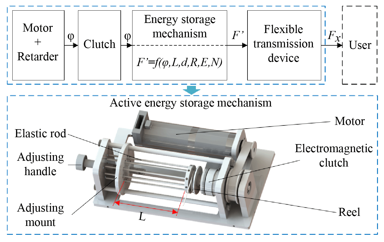
According to the proposed method, an active energy storage mechanism is designed. An electromagnetic clutch is driven by a motor with a synchronous belt, the output of the electromagnetic clutch is connected with a reel, and a Bowden cable is used to achieve flexible transmission and is wound on the reel. One end of the elastic rod is fixed on the reel, and the other end passes through the hole on the adjusting mount. The adjusting mount is connected to the adjusting handle through threads. The adjusting mount can be moved along the guide bar to adjust the deformation length of the elastic rod (L) by rotating the adjusting handle. Then the assisted force can be changed.
The proposed active energy storage method works in two stages. When there is no torque generated by the ankle, the electromagnetic clutch is closed. The motor drives the elastic rod between the adjusting mount and the reel to generate deformation, and then the energy storage is achieved. When the ankle generates torque, the electromagnetic clutch is opened. Then the reel is driven to rotate by the elastic rod in the energy storage mechanism, and the assisted force on the user's heel is generated through the flexible transmission device, thereby providing the assisted force for the ankle. The output force (F′) is determined by multiple parameters such as the angular displacement (φ), the deformation length of the elastic rod (L), the diameter of the elastic rod (d), the radius of the reel (R), the elastic modulus of the elastic rod (E), and the number of elastic rods (N). The proposed active energy storage method has the following advantages:
- (a)
During walking, the ankle torque generation time is short. The active energy storage method can store energy in the ankle's non-force-generation stage in a gait cycle. Then the energy storage time is long. Therefore, a small power motor can be used with a large reduction ratio gearbox to provide larger assisted torque for the user.
- (b)
The deformation length of the elastic rod in the energy storage mechanism can be adjusted according to the load of the user. Therefore, the stored energy can be changed, and appropriate assisted forces can be provided for different loads.
- (c)
According to the user gait cycle, the controller only needs to control the motor to rotate at a certain angle and control the electromagnetic clutch to open or close. The controller does not need to control the assisted force in real time, so the control system is easy to develop.
3.2 Sketch of ankle assistance robot
Based on the proposed active energy storage method, a wearable ankle assistance robot is designed. A sketch of the robot is shown in Fig. 2. A battery, motor, controller, and active energy storage mechanism are set at the human waist. A Bowden cable is arranged along the outside of the thigh. Two IMUs are arranged on the outside of each thigh, and pressure sensors are arranged on the heels. The pressure sensors are combined with the two kinds of sensing data to obtain the user's gait cycle information. One end of the Bowden cable is connected to the energy storage mechanism, and the other end is connected to the heel of the human body to achieve flexible transmission, and the assisted force is transferred to the heel by the Bowden cable. Because of the transmission loss and hysteresis of the Bowden cable (Veneman et al., 2006), the assisted force (Fx) is less than the output force (F′). The relationship between the assisted force (Fx) and the output force (F′) can be calculated with
where f is the friction coefficient, and αx is the wrap angle between two ends.
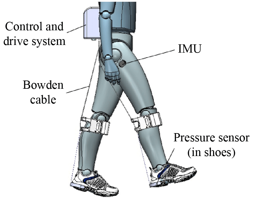
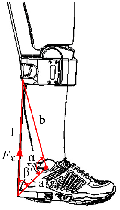
Figure 3 shows the assisted force acting on the human heel. The changes in the steel wire length of the Bowden cable and the assisted torque for the ankle can be estimated with
where l0 is the length of the steel wire, α0 is the initial angle between line a and line b, Δl is the change of the steel wire length, and Tx is the assisted torque for the ankle. The change of the steel wire length (Δl) is used to calculate the angular displacement (φ) of the active energy storage mechanism, and the assisted torque (Tx) is used to estimate the torque for the ankle that is generated by the assisted force of the robot.
3.3 Mechanical analysis of elastic rod
The assisted force is generated by the deformation of the elastic rod. An appropriate assisted force can be provided by designing the diameter and length of the elastic rod appropriately. The cross-section of the elastic rod is set to be circular and distributed along the reel uniformly. Figure 4 shows the deformation effect of the elastic rod during torque (with two elastic rods).
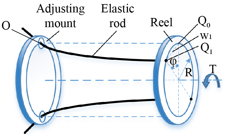
When the reel is driven by the motor to rotate from the balance position to a certain angle, the contact point of the elastic rod and the reel is transferred from point Q0 to point Q1 in the circumferential direction. The relationship between the displacement (w1) and the rotation angle (φ) can be expressed by
where R is the rotation radius of the elastic rod end.
Owing to the structural characteristics of the energy storage mechanism, the elastic rod only has bending deformation and no torsional deformation, so the deformation of the elastic rod can be approximated as the bending of a cantilever beam. With the rotation of the reel, a concentrated load opposite to the rotation direction is applied to the elastic rod by the adjusting mount. The cantilever beam bending model is shown in Fig. 5.
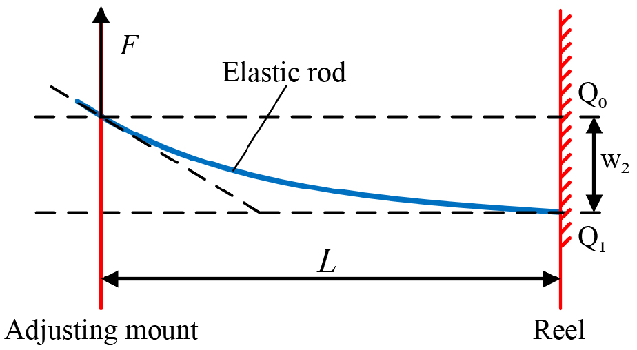
Because the deformation of the elastic rod is approximated as the bending of the cantilever beam, the deflection value (w2) can be calculated by
where F is the concentrated load on the free end of the elastic rod, L is the effective bending length of the elastic rod, E is the elastic modulus of the elastic rod, and I is the section moment of inertia of the elastic rod.
According to Figs. 4 and 5, w1 is equal to w2. Then the force F acting on the end of the elastic rod can be obtained from Eqs. (4) and (5). The force F can be described as
The moment of inertia of a circular section can be calculated with
where d is the diameter of the elastic rod. Fc that generates torque on the reel is the component of the force F in the vertical radius, which can be calculated with
The torque generate by one elastic rod can be calculated with
3.4 Energy storage capacity analysis
Based on the working principle of the energy storage mechanism, the energy storage capacity of the energy storage mechanism is analyzed, which can provide a basis for the energy storage control and assisted force adjustment of the robot.
By comparing the performance parameters such as the elastic modulus and tensile strength, beryllium copper is selected as the material of the elastic rod. The elastic modulus (E) and yield strength of beryllium copper (σs) are 128 GPa and 1035 MPa respectively. During energy storage, the elastic rod is bent and deformed, and the maximum bending stress can be calculated with
where Wz is the bending section coefficient of the circular section rod, and M is the bending moment of the elastic rod at the adjusting mount. Wz and M can be calculated with
Then the maximum bending stress is
Considering the safety of the energy storage mechanism, it is necessary to ensure that the elastic rod meets the requirements of the allowable load stress during use, and Eq. (13) should be satisfied in the design.
The allowable tensile stress of an elastic rod is the yield strength σs divided by the safety factor n, then
With Eqs. (8) and (14), the minimum length of the selected elastic rod can be calculated with
It can be known from Eq. (15) that after the parameters of the elastic rod are determined, the minimum selected length is only related to the rotation angle (φ) of the reel. A circular section elastic rod with a diameter of 2 mm is selected, and the safety factor n is set to 1.5. Considering factors such as the volume and the installation of the active energy storage mechanism, the distance R from the contact point of the elastic rod to the center of the reel is set to 15 mm. The rotation angle of the reel is calculated based on the structure of the flexible transmission device and the range of the ankle movement. Then, with Eq. (15), the minimum length of the elastic rod can be calculated, which should not be less than 64.75 mm. The adjustment range of the elastic rod is set to 65–80 mm.
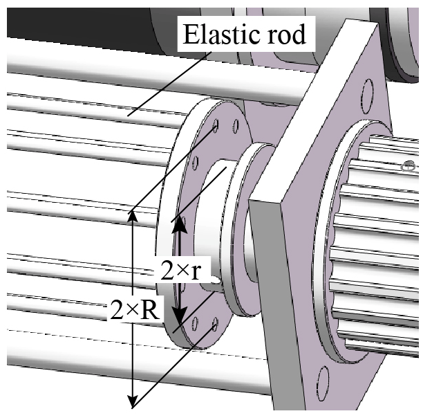
According to the force requirements of the ankle joint and the structure of the energy storage mechanism, the number of elastic rods (N) is set to 10. The torque generated by all elastic rods can be calculated with
The winding radius r of the wire is 12.5 mm (the r is shown in Fig. 6), and the output force (F′) generated by the torque T′ acting on the Bowdoin line can be calculated with Eq. (17):
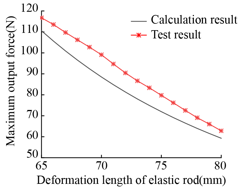
According to the adjustment range of the elastic rod and the rotation angle of the reel, the relationship between the maximum output force and the deformation length of the elastic rod can be obtained from Eqs. (16) and (17). The result is shown in Fig. 10. The output force of the designed active energy storage mechanism decreases monotonically with the increase in the deformation length of the elastic rod, an approximately linear relationship, so it is convenient for the adjustment of the output force.
4.1 Moment of assistance
To realize the power-assisted function, it is necessary to obtain the moments when the ankle generates force and when the robot provides assisted force. Much information can be used for robot decision making (Qiao et al., 2022; Qi et al., 2021), but it is difficult to obtain the moment of assistance directly, so a method is proposed to detect the gait cycle by combining the information on the hip joint angle and the plantar pressure. Then the moment of assistance can be calculated.
An IMU is placed on the outside of the thigh to obtain the hip angle information during walking. When the human body is standing, the thigh is perpendicular to the ground, and the hip joint angle at this time is defined as 0∘. The angle is positive when flexed, and the angle is negative when extended. The human gait cycle is shown in Fig. 7. According to the literature (Dai and Tang, 1982), the minimum value of the hip angle appears at 53.8 % of the gait cycle during walking, and then the angle increases until 84.6 % of the gait cycle.
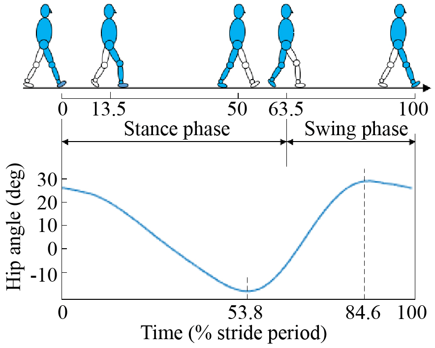
During walking, the gait cycles are different, but the ratios between the hip flexion times and the gait cycles are approximately equal. Therefore, the hip flexion time and the ratio can be used to predict the gait cycle. The ankle does positive work between 40 % and 60 % of the gait cycle (Collins et al., 2005), and the peak value of the ankle torque during walking is at about 50.1 % of the gait cycle (Tang and Dai, 1986), so the starting time of the assistance should between 40 % and 50.1 % of the gait cycle. In this study, the starting time of the assistance is set at 43 % of the gait cycle (during the experiment, testers feel comfortable at this moment). Based on the characteristics of human walking, the pressure sensor is used to obtain the heel landing time as the start time of a gait cycle. The IMU is used to obtain the angular displacement of the hip. After the hip movement peak time is detected, the hip flexion time is obtained by subtracting the trough time. At the same time, the gait cycle time is obtained by using the difference between the two peak times. Then the ratio is obtained with the flexion time divided by the cycle time. The predicted gait cycle can be obtained using the flexion time of the previous gait cycle divided by the average ratio of the previous three gait cycles. The starting time of the power assistance can be calculated with
where k is the current gait number, k-1 is the last gait number, p is the predicted ratio, Tpre is the predicted gait cycle, tpeak is the peak time of the hip, ttrough is the trough time of the hip, tzero is the start time of the gait, and tassist is the moment when the robot begins to provide assisted force. The proposed assistance moment calculation method has the following advantages:
- (a)
The gait cycle is predicted using the hip angular displacement, whose shape is similar to a sinusoidal curve, with only one maximum and one minimum value in a gait cycle, so the prediction result is more stable and accurate.
- (b)
Using the pressure information of both heels and the angular displacement of the hips, the human states of walking and standing can be estimated accurately, so the incorrect operation of the robot can be avoided.
4.2 Control method
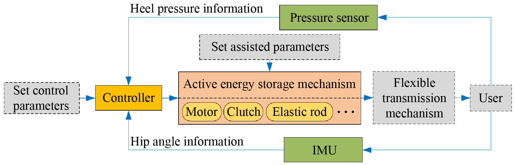
The robot control system is made up primarily of a controller, an IMU, a pressure sensor, a DC motor, and an electromagnetic clutch. The robot controlling principle is shown in Fig. 8. First, the gait information is collected by the IMU and the pressure sensor and is then transmitted to the controller. Second, the assistance time is calculated by the controller with the heel pressure information and the hip joint angular displacement. Third, the control command is sent to the DC servo motor driver and the electromagnetic clutch to coordinate the motor and clutch.
The same control method is applied to the left leg and the right leg of the user. The start time of the energy storage is when the leg is in the swing phase and the angular displacement of the hip joint is 0∘. After the energy storage start time is obtained, the electromagnetic clutch is closed by the controller. At the same time, the motor is controlled to rotate for energy storage, and the motor stops after rotating to the preset angle.
After the start time of the gait cycle is obtained according to the heel pressure information, the starting time of assistance is calculated with Eq. (18). When the power assistance time occurs, the electromagnetic clutch is opened, and the energy storage mechanism drives the human ankle movement through the flexible transmission mechanism to achieve walking assistance.
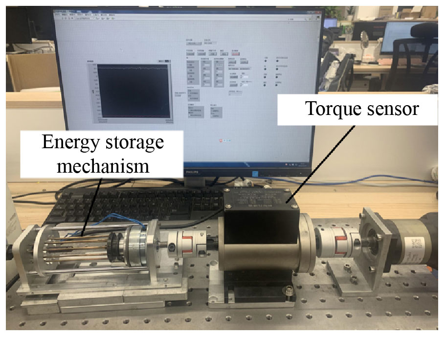
5.1 Test of energy storage mechanism output force
An experimental platform is built to obtain the maximum output force of the energy storage mechanism. This platform is shown in Fig. 9. The energy storage mechanism is connected to the dynamic torque sensor, and a servo motor is used to drive the energy storage mechanism to rotate. The maximum output force is calculated with the test torque divided by the winding radius r of the wire. The result is shown in Fig. 10. The test results and calculation results have similar trend. But the tested output forces are slightly greater than calculated values, with an approximately constant difference. This may be for several reasons, such as the difference between the calculated parameters and the actual parameters of elastic rods and other parts, the axiality error between the torque sensor and the energy storage mechanism, and friction. The output force supplied by the robot should reference the test result. With the output force, the assisted force for the user can be calculated with Eq. (1).
5.2 Walking assistance experiment
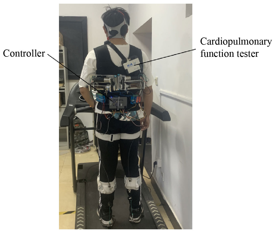
The prototype of the wearable ankle assistance robot is shown in Fig. 11. According to the maximum torque required by the energy storage mechanism, a 90 W DC servo motor (RE35 Maxon) and an electromagnetic clutch (HB-YC-42, Shenzhen Haibosi Technology Co., Ltd) are selected, and the reduction ratio of the gearbox is 26:1. An NI myRIO-1900 (from NI Inc.) is used as the controller for the robot. The active energy storage mechanism and the controller are placed at the user's back and waist, and the mobile power supply is arranged behind the controller. The IMUs (BWT901CL, WitMotion ShenZhen Co., Ltd) are fixed in place by a flexible bandage. The pressure sensors (FSR 402, SparkFun Electronics Inc.) are placed in the heels of the shoes. The cardiopulmonary function tester (K4b2, Cosmed Inc.) is used to measure the metabolic cost of the user. The walking frequency of a healthy person is about 0.8 Hz; when loaded with weight, the walking frequency maybe lower. The control cycle was set to be 40 ms, which means the control frequency is 25 Hz.
During the experiment, participants walk on a treadmill, and the metabolic costs of the participants in three states are measured: the resting state, walking without the assisted robot, and walking with the assisted robot. The net metabolic cost is obtained by subtracting the resting state metabolic cost from the walking metabolic cost, which is used to indicate the energy expenditure during walking. The assistance effect of the robot is evaluated by comparing the net metabolic costs of wearing and not wearing the robot. The data unit of the cardiopulmonary function tester is calories per second (cal s−1) in this study, and the unit of the metabolic cost is watts per kilogram (W kg−1); the value conversion can be realized by the following equation:
where MC is the value (in W kg−1) of the metabolic cost, D is the value (in cal s−1) collected by the cardiopulmonary function tester, and Mb is the body weight (in kg) of the participant.
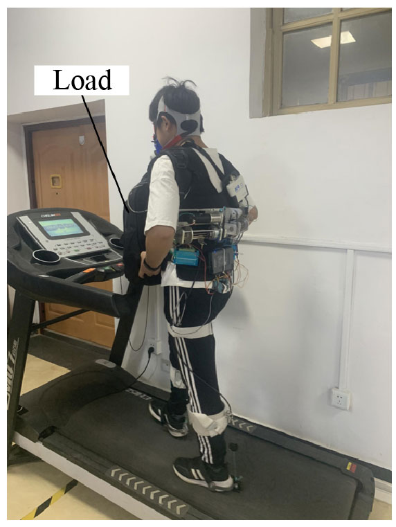
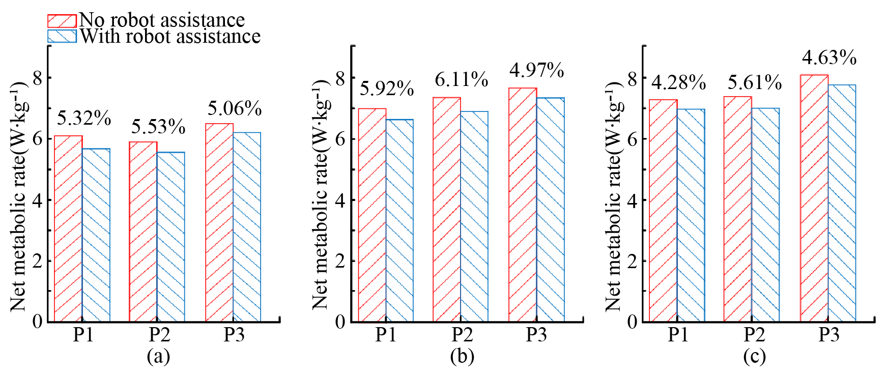
Figure 13Net metabolic cost without robot assistance and with robot assistance under different loads. (a) Load: 0 kg. (b) Load: 4 kg. (c) Load: 8 kg.
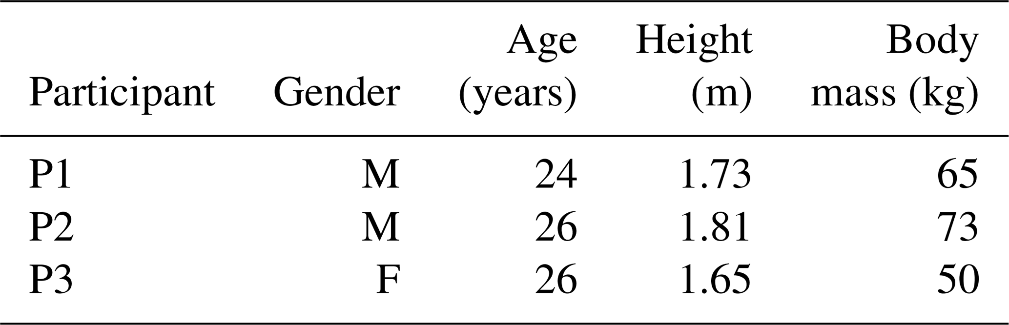
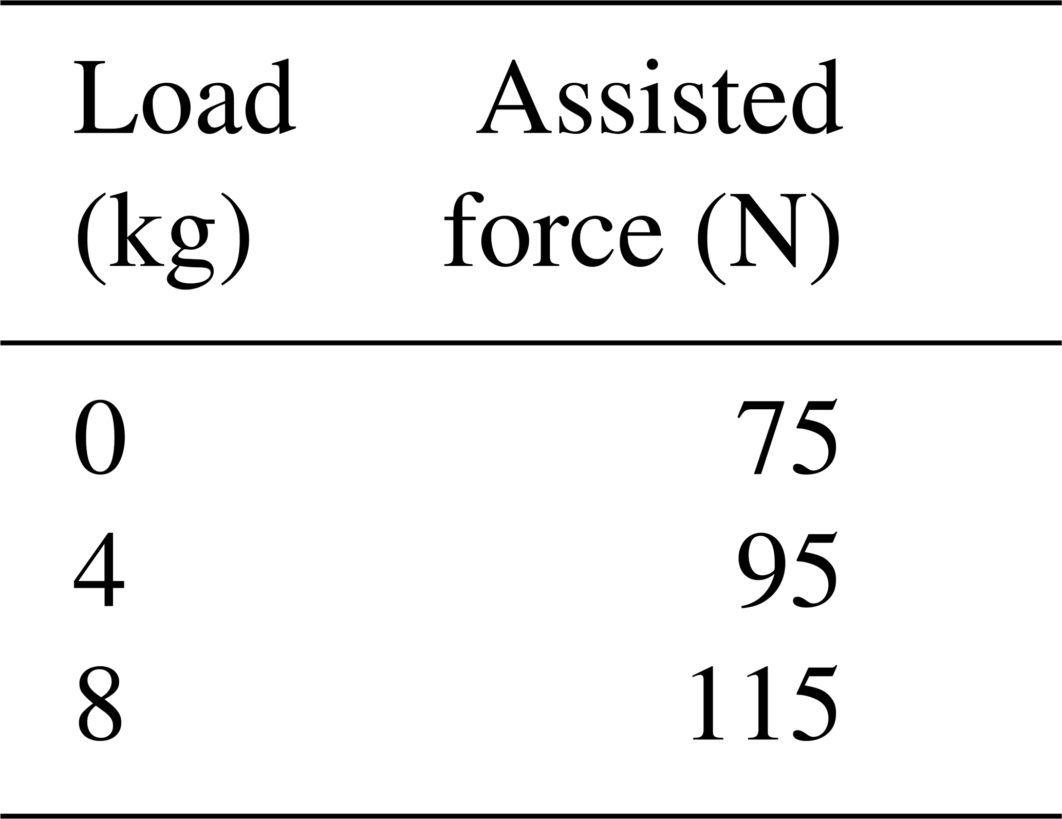
Three participants participate in the experiment, and the information on the participants is shown in Table 1. Different assisted forces are supplied to participants with different loads. Because the accurate calculation of the assisted force is difficult, the output force of the energy storage mechanism is taken as a reference. The load and the assisted force are shown in Table 2.
In each experiment, participants walk for 6 min at a speed of 4.5 km h−1 (Fig. 12), and the net metabolic cost data of the last 2 min were analyzed. The net metabolic costs of the three participants are shown in Fig. 13.
It can be observed from Fig. 13 that the average net metabolic cost is reduced by 5.30 % when the participants have no load, and the maximum reduction is 5.53 %. When a 4 kg load is carried by the participants, the average net metabolic cost is reduced by 5.67 %, and the maximum reduction is 6.11 %. When an 8 kg load is carried by the participants, the average net metabolic cost is reduced by 4.84 %, and the maximum reduction is 5.61 %.
The test result shows that the net metabolic costs of all the participants under different loads are reduced. This means that the developed wearable ankle assistance robot can reduce the energy consumption of the human body by providing assisted force for the ankle. The net metabolic cost reductions when the participants are under loads are close to the reductions in the case without loads. This indicates that the robot's function of adjusting the assisted force for different loads is effective.
Although the expected functions are realized, there are still some problems that need to be improved. For example, the weight of the developed robot is about 5.3 kg, and participants feel heavier after wearing it. Some energy is consumed by the friction that is generated in the process of the Bowden cable working. The robot is inconvenient to wear and take off. About 2 min is needed to wear it or take it off by a participant without the help of others. These problems impact the assistance effect of the robot and will be improved in future study.
Based on the proposed active energy storage ankle assistance method, an active energy storage mechanism is designed and developed that achieves the function of energy storage using a small power motor with a larger reduction ratio gearbox. By adjusting the deformation length of the elastic rods, the energy storage capacity of the energy storage mechanism can be changed, thereby providing an adjustable assisted force for the user.
With the information on the IMU, the information on the pressure sensor, and human gait cycle characteristics, the moment of assisting the ankle can be obtained. According to the assistance time and the start time of the energy storage, the movement of the motor and the electromagnetic clutch can be controlled accurately with the controller. Then the functions of storage and release of energy can be realized, and the assisted force can be provided by the robot for the user.
A wearable ankle assistance robot with the function of active energy storage is developed, and a walking assistance experiment is carried out. The experimental results show that the net metabolic cost of the participants is reduced by averages of 5.30 %, 5.67 %, and 4.84 % with 0, 4, and 8 kg loads respectively. The results show that with different loads, the robot can reduce participant energy consumption, and the assisted walking function is achieved.
All data included in this study are available upon request by contact with the corresponding author.
Conceptualization, JL and DY; investigation, KY; methodology, JL; project administration, JL; resources, DY; software, KY; validation, JL; writing (original draft preparation), KY; writing (review and editing), JL and KY. All authors have read and agreed to the published version of the manuscript.
The contact author has declared that none of the authors has any competing interests.
Publisher’s note: Copernicus Publications remains neutral with regard to jurisdictional claims made in the text, published maps, institutional affiliations, or any other geographical representation in this paper. While Copernicus Publications makes every effort to include appropriate place names, the final responsibility lies with the authors.
The authors would like to thank Shijie Guo for his valuable insight and advice. The authors would also like to thank Jingyuan Qi, Liang Zhao, and Lei Zhao for their help with the testing of human subjects.
This research has been supported by the National Natural Science Foundation of China (grant no. U1813222).
This paper was edited by Zi Bin and reviewed by six anonymous referees.
Asbeck, A. T., De Rossi, S. M., Holt, K. G., and Walsh, C. J.: A biologically inspired soft exosuit for walking assistance, Int. J. Rob. Res., 34, 744–762, https://doi.org/10.1177/0278364914562476, 2015.
Browning, R. C., Modica, J. R., Kram, R., and Goswami, A.: The effects of adding mass to the legs on the energetics and biomechanics of walking, Med. Sci. Sports Exerc., 39, 515–525, https://doi.org/10.1249/mss.0b013e31802b3562, 2007.
Collins, S., Ruina, A., Tedrake, R., and Wisse, M.: Efficient bipedal robots based on passive-dynamic walkers, Science, 307, 1082–1085, https://doi.org/10.1126/science.1107799, 2005.
Collins, S. H., Wiggin, M. B., and Sawicki, G. S.: Reducing the energy cost of human walking using an unpowered exoskeleton, Nature, 522, 212–215, https://doi.org/10.1038/nature14288, 2015.
Dai, K. R. and Tang, R. G.: Observation of gait when walking at normal speed on the ground, Chin. J. Biomed. Eng., 1, 15–21, 1982.
Diller, S., Majidi, C., and Collins, S. H.: A lightweight, low-power electroadhesive clutch and spring for exoskeleton actuation, in: IEEE International Conference on Robotics and Automation (ICRA), Stockholm, Sweden, 16–21 May 2016, 682–689, https://doi.org/10.1109/ICRA.2016.7487194, 2016.
Gordon, K. E., Sawicki, G. S., and Ferris, D. P.: Mechanical performance of artificial pneumatic muscles to power an ankle–foot orthosis, J. Biomech., 39, 1832–1841, https://doi.org/10.1016/j.jbiomech.2005.05.018, 2006.
Galle, S., Malcolm, P., Derave, W., and De Clercq, D.: Enhancing performance during inclined loaded walking with a powered ankle-foot exoskeleton, Eur. J. Appl. Physiol., 114, 2341–2351, https://doi.org/10.1007/s00421-014-2955-1, 2014.
Han, Y., Guo, S., Zhang, L., Xi, F. J., and Lu, W.: Tip-Over Stability Analysis of a Pelvic Support Walking Robot, J. Health. Eng., 2020, 1506250, https://doi.org/10.1155/2020/1506250, 2020.
Hogan, M. C., Ingham, E., and Kurdak, S. S.: Contraction duration affects metabolic energy cost and fatigue in skeletal muscle, Am. J. Physiol. Renal Physiol., 274, 397–402, https://doi.org/10.1152/ajpendo.1998.274.3.E397, 1998.
Jones, G. R.: Human load carriage: the ergonomic assessment and development of military load carriage systems, PhD thesis, Loughborough University, UK, 33–42, PID: uk.bl.ethos.440362, 2005.
Kang, I., Peterson, R. R., Herrin, K. R., Mazumdar, A., and Young, A. J.: Design and Validation of a Torque-Controllable Series Elastic Actuator-Based Hip Exoskeleton for Dynamic Locomotion, J. Mech. Robot., 15, 021007, https://doi.org/10.1115/1.4054724 2022.
Mala, J., Szivak, T. K., Flanagan, S. D., Comstock, B. A., Laferrier, J. Z., Maresh, C. M., and Kraemer, W. J.: The role of strength and power during performance of high intensity military tasks under heavy load carriage, US Army Med. Dep. J., 3–11, 2015.
Mooney, L. M. and Herr, H. M.: Biomechanical walking mechanisms underlying the metabolic reduction caused by an autonomous exoskeleton, J. Neuroeng. Rehabilitation, 13, 1–12, https://doi.org/10.1186/s12984-016-0111-3, 2016.
Mooney, L. M., Rouse, E. J., and Herr, H. M.: Autonomous exoskeleton reduces metabolic cost of human walking during load carriage, J. Neuroeng. Rehabilitation, 11, 1–11, https://doi.org/10.1186/1743-0003-11-80, 2014.
Park, Y. L., Chen, B. R., Pérez-Arancibia, N. O., Young, D., Stirling, L., Wood, R. J., Goldfield, E. C., and Nagpal, R.: Design and control of a bio-inspired soft wearable robotic device for ankle-foot rehabilitation, Bioinspir. Biomim., 9, 016007, https://doi.org/10.1088/1748-3182/9/1/016007, 2014.
Qiao, H., Zhang, S., Chen, Z., and Wang, H.: Improving performance of robots using human-inspired approaches: a survey, Sci. China Inf. Sci., 65, 1–31, https://doi.org/10.1007/s11432-022-3606-1, 2022.
Qi, W., Oyur, S. E., Li, Z., Marzullo, A., and Song, R.: Multi-sensor guided hand gesture recognition for a teleoperated robot using a recurrent neural network, IEEE Robot. Autom. Lett., 6, 6309–6045, https://doi.org/10.1109/LRA.2021.3089999, 2021.
Saelens, B. E., Sallis, J. F., and Frank, L. D.: Environmental correlates of walking and cycling: findings from the transportation, urban design, and planning literatures, Ann. Behav. Med., 25, 80–91, https://doi.org/10.1207/S15324796ABM2502_03, 2003.
Sawicki, G. S. and Ferris, D. P.: Powered ankle exoskeletons reveal the metabolic cost of plantar flexor mechanical work during walking with longer steps at constant step frequency, J. Exp. Biol., 212, 21–31, https://doi.org/10.1242/jeb.017269, 2009.
Shao, Y., Zhang, W., Su, Y., and Ding, X.: Design and optimization of load-adaptive actuator with variable stiffness for compact ankle exoskeleton, Mech. Mach. Theory, 161, 104323, https://doi.org/10.1016/j.mechmachtheory.2021.104323, 2021.
Tang, R. G. and Dai, K. R.: Analysis of ankle joint force when walking on level ground, J. Shanghai Second Med. Univ., 126–129, 143–189, 1986.
Tsukahara, A., Hasegawa, Y., Eguchi, K., and Sankai, Y: Restoration of gait for spinal cord injury patients using HAL with intention estimator for preferable swing speed, IEEE. Trans. Biomed. Eng., 23, 308–318, https://doi.org/10.1109/TNSRE.2014.2364618, 2014.
Veneman, J. F., Ekkelenkamp, R., Kruidhof, R., van der Helm, F. C., and van der Kooij, H.: A series elastic-and bowden-cable-based actuation system for use as torque actuator in exoskeleton-type robots, Int. J. Rob. Res., 25, 261–281, https://doi.org/10.1177/0278364906063829, 2006.
Wang, T. M., Pei, X., Hou, T. G., Fan, Y. B., Yang, X., Herr, H. M., and Yang, X. B.: An untethered cable-driven ankle exoskeleton with plantarflexion-dorsiflexion bidirectional movement assistance, Front. Inf. Technol. Electron. Eng., 21, 723–739, https://doi.org/10.1631/FITEE.1900455, 2020.
Wang, W., Chen, J., Ji, Y., Jin, W., Liu, J., and Zhang, J.: Evaluation of lower leg muscle activities during human walking assisted by an ankle exoskeleton, IEEE Trans. Industr. Inform., 16, 7168–7176, https://doi.org/10.1109/TII.2020.2974232, 2020a.
Wang, W., Zhang, L., Liu, J., Zhang, B., and Huang, Q.: A real-time walking pattern recognition method for soft knee power assist wear, Int. J. Adv. Robot. Syst., 17, 1729881420925291, https://doi.org/10.1177/1729881420925291, 2020b.
Witte, K. A., Zhang, J., Jackson, R. W., and Collins, S. H.: Design of two lightweight, high-bandwidth torque-controlled ankle exoskeletons, in: IEEE International Conference on Robotics and Automation (ICRA), Seattle, WA, USA, 26–30 May 2015, 1223–1228, https://doi.org/10.1109/ICRA.2015.7139347, 2015.
Xie, L., Wang, Z., Huang, G., Liu, B., and Zhou, Z.: Mechanical Efficiency Investigation of an Ankle-Assisted Robot for Human Walking With a Backpack-Load, J. Biomech. Eng., 143, 111010, https://doi.org/10.1115/1.4051434, 2021.
Yandell, M. B., Tacca, J. R., and Zelik, K. E.: Design of a low profile, unpowered ankle exoskeleton that fits under clothes: overcoming practical barriers to widespread societal adoption, IEEE Trans Neural Netw. Learn. Syst., 27, 712–723, https://doi.org/10.1109/TNSRE.2019.2904924, 2019.
Zoss, A. B., Kazerooni, H., and Chu, A.: Biomechanical design of the Berkeley lower extremity exoskeleton (BLEEX), IEEE ASME Trans. Mechatron., 11, 128–138, https://doi.org/10.1109/TMECH.2006.871087, 2006.