the Creative Commons Attribution 4.0 License.
the Creative Commons Attribution 4.0 License.
 | 27 Nov 2020
Novel semiactive suspension using a magnetorheological elastomer (MRE)-based absorber and adaptive neural network controller for systems with input constraints
Xuan Bao Nguyen
Toshihiko Komatsuzaki
Hoa Thi Truong
For most existing semiactive systems, it is commonly known that the stability and tracking performance will deteriorate in a real application due to the input constraints and nonlinearity in the system. In this study, in order to overcome the above shortcomings, a novel bench-scale suspension plant using a magnetorheological elastomer (MRE)-based absorber accompanied with an adaptive and global neural-network-based tracking controller is introduced. The adaptive neural network (ANN) is used to estimate the uncertain dynamics of the quarter-car model. The novel scheme consists of three parts, including a conventional ANN controller dominating the active region of neurons, a robust controller serving as a temporary controller to pull back the state into the active region when the neural approximation falls outside, and a switch to be used to monitor the activation of the neural part and switch the control authority between the above two controllers. The controller ensures that a globally uniform ultimate boundedness can be achieved. Furthermore, an auxiliary design system was added to the controller in order to deal with the effects of input constraints, and the state was analyzed for the tracking of the stabilization. The control scheme ensures that the output of the system converges to the vicinity of a reference trajectory and all the signals are globally, uniformly, and ultimately bounded. The simulation and experimental results demonstrate that the proposed controller can effectively suppress the vibrations of the semiactive quarter car.
- Article
(5991 KB) - Full-text XML
- BibTeX
- EndNote


The suspension system is a critical component in vehicles that ensure comfort and safety to humans on different road surface conditions. Vehicle suspension systems are used to absorb uncomfortable vibrations of a car body due to wheel excitation. These systems can be classified into three categories based on their energy-absorbing capability, namely passive, active, and semiactive suspensions. A passive suspension system has the ability to absorb energy by a spring-damper system. The system parameters are constant and are chosen based on loading capacity and road disturbance. An active suspension system usually contains an actuator in addition to the basic spring-damper constitution. The actuator generates an active force to absorb the residual energy of the passive system in various operating conditions. However, the mechanical components comprising the active systems are massive and consume a lot of energy (Cao et al., 2008; Li et al., 2014, 2012). The semiactive suspension system has the advantages of the device constitution being compact and flexible while providing the isolation performance close to the active suspensions. The system can adjust the damping and/or stiffness coefficients to achieve optimum energy absorption. Semiactive control strategies have been studied and used in the field of vehicle dynamics. In these applications, a magnetorheological fluid (MRF) damper has been used as the smart dampers (El Majdoub et al., 2015; Nie et al., 2017).
A magnetorheological elastomer (MRE), which is an elastomeric composite incorporating ferrous particles, is an intelligent material that can change its elastic modulus depending on the magnetic field. The material can be used to change the dynamic property of the system. MRE overcomes the disadvantages of MRF, such as sedimentation and aggregation, and MRE properties are strongly nonlinear functions of magnetic flux density, excitation frequency, and displacement amplitude. In recent years, many studies have been reported regarding improvement and investigation of the mechanical properties of MRE (Gong et al., 2005; Zhang et al., 2008; Nguyen el at., 2017b). In order to design MRE-based systems for various technical applications, several numerical models have been proposed to represent the dynamic behaviors of MRE (Li et al., 2010; Eem et al., 2012; Yang et al., 2013; Norouzi et al., 2016). The semiactive suspension system using MRE is expected to be nearly as efficient as a fully active system in reducing vibration without consuming more energy. It is also a safe system; even if the control fails, the device can still work as a passive suspension system. Developing a novel suspension system using an MRE-based absorber and designing a new control scheme in accordance with the physical characteristics of the MRE is our motivation.
Traditional semiactive controllers, such as the on–off controller, fuzzy controller, and clip-optimal controller, do not guarantee system stability (Liao et al., 2011; Zhu et al., 2014; Nguyen et al., 2018a; Jansen and Dyke, 2000). Recently, many scientists have proposed improved versions of the controllers, such as the adaptive sliding mode controller (Fei and Xin, 2012; Fallah and Taghikhany, 2015), the adaptive fuzzy sliding mode controller (Nguyen et al., 2017a; Phu et al., 2014), and the robust adaptive controller for semiactive controller (Nguyen et al., 2018b). These methods guarantee zero convergence of the displacement response and provide robust stability. However, they usually require a large amount of control force in the case of the uncertain dynamic system.
A semiactive suspension system requires an appropriate semiactive controller. There are a lot of different semiactive control strategies which improve vibration control performance using MRE and MRF, as summarized by Choi et al. (2016). An adaptive neural network (ANN) could be used to solve problems related to the system's highly nonlinear property, uncertainty, and singularity (Zhang et al., 2000). It is a promising approach that can ensure the good performance of the semiactive suspension systems. In practice, traditional ANN controllers, known as the semiglobal and tracking implementation, are serious or even unstable. Adaptive backstepping is an adaptive control technique for nonlinear systems that performed well in active suspension (Yagiz and Hacioglu, 2008; Sun et al., 2013), but the actuator constraint was not considered in the controller design. Therefore, these controllers are difficult to apply in practical semiactive systems.
In addition, the limitation of the semiactive device is an issue that needs to be investigated. This problem is complicated due to the nonlinearity of the system and hysteretic property of the material, which accordingly causes the actuator to poorly respond to the controller requirements. The clipping control algorithm is widely used in which the active force is clipped to accommodate the semiactive system. The controller is divided into two stages, namely an ideal active controller and a passive controller in which the control variable is switched by a clipped on–off algorithm (Jansen and Dyke, 2000). Consequently, the conventional controller becomes less efficient, and it can even lead the system to instability. Therefore, the actuator limitation should explicitly be considered in the controller design. A few researchers have taken into account the limits of control force in designing a controller in engineering systems (Chen et al., 2011; He et al., 2016; Sun et al., 2015). The semiactive vibration systems using an MRF damper or MRE-based device are still facing challenges due to the nonlinearity in the dynamic model and input constraints. Developing a novel controller for systems with the force constraint is vital for practical semiactive applications. The physical constraints of the actuator should be clarified and an auxiliary system state needs to be designed to handle the operation of the controller.
In this study, a new control strategy was developed for a semiactive suspension system using MRE-based absorber. The contributions of this study are listed as follows:
-
A novel semiactive suspension, which can tune its own natural frequency for a wide range, comprising of an MRE-based absorber and a novel controller was developed. The input constraint issues that exist in the semiactive system are also presented.
-
We designed a novel controller which consists of three components:
- a.
a traditional adaptive neural network controller operating in the active zone of neurons,
- b.
a robust controller which serves as a temporary controller in order to pull back the system's state into the active zone, and
- c.
a smooth switching function to monitor whether the value is inside or outside the zone and to switch the authority between two controllers.
- a.
-
The active controller cannot perform well for semiactive system because of the force constraint. In this study, an auxiliary controller was proposed to take the constraint into account.
-
The proposed suspension system was used for controlling vibration of a car model. The simulation and experimental results showed the efficiency of the control algorithm.
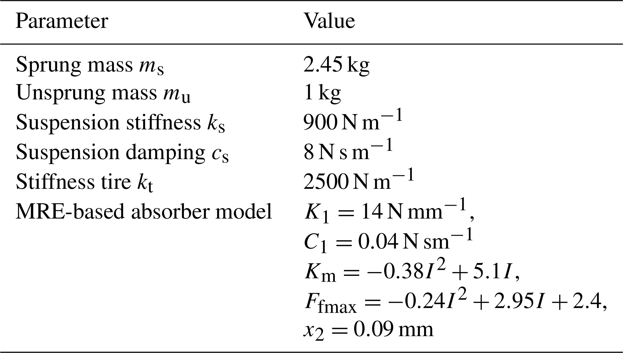
A bench-scale suspension system was designed to evaluate the effectiveness of the MRE-based absorber and proposed control algorithm. System parameters are the same with the Quanser suspension system which has become well known, and many scientists have used this bench-scale system to test their developed control algorithms for active suspension system (Sun et al., 2015; Sistla et al., 2020; Pan at al., 2015; Pusadkar et al., 2018). The parameter values are summarized in Table 1. The main advantages of the proposed system are that it is simple and lightweight. It requires fewer components than other types of active suspension setups, uses less energy, and also takes up less space. This makes the system particularly desirable for use on small cars. However, MRE-based devices generally work effectively within a small displacement range, and their magnetic system is complex for the large device. The new approach of this system is to exploit the advantage of the stiffness tunability of the MRE-based absorber. Recently, the MRE material has attracted many researchers; however, the application of the material is very limited in suspension systems. Experiments were also conducted to illustrate the effectiveness of the developed system shown in Fig. 1b. In the system, ms represents the sprung mass of a car body, mu the unsprung mass of a tire, kt the rubber stiffness of the tire, and ks and cs the stiffness and damping of the suspension, respectively.
The absorber developed by one of the authors was used as a semiactive actuator of the suspension system (Komatsuzaki et al., 2016; Nguyen et al., 2020). The absorber consists of a set of steel cores, a brass inner core, a magnetic coil, two ring-shaped MREs, and duralumin housing, as shown in Fig. 1a, whose properties can be extended over a wide frequency range.
We performed experiments to evaluate the mechanical properties of the system by applying varied electric currents. A swept-sine signal, whose frequency varied from 1 to 64 Hz, was used to excite the base. Displacements at the base and at the sprung mass were measured using displacement sensors. A fast Fourier transform (FFT) analyzer was used to analyze the transfer function for different current values. Furthermore, the following current switching mode was also investigated:
In Eq. (1), I is the input current to the absorber switched between zero and the maximum values based on detected frequency f, and f0 is the nominal frequency that separates the lower and higher regions of the tunable frequency range.
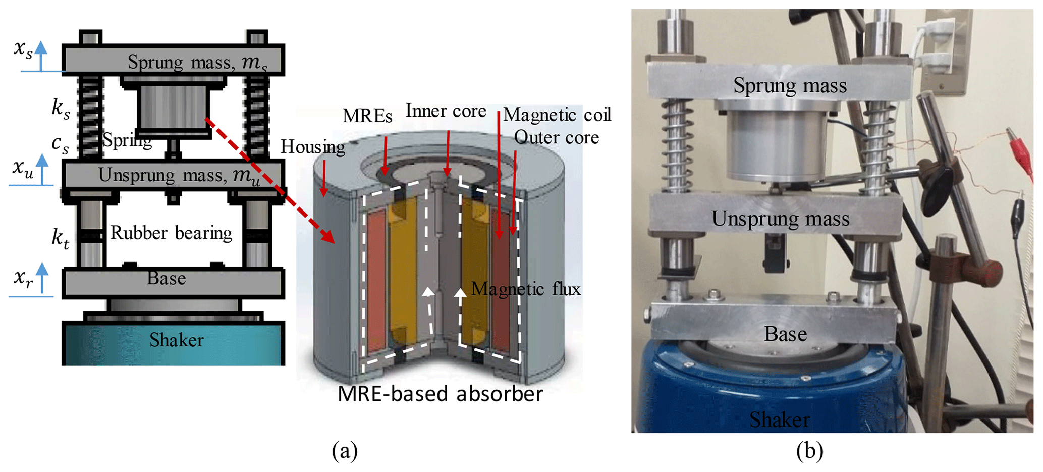
Figure 1A semiactive suspension system using an MRE-based absorber. (a) Schematic illustration. (b) A photo of the setup.
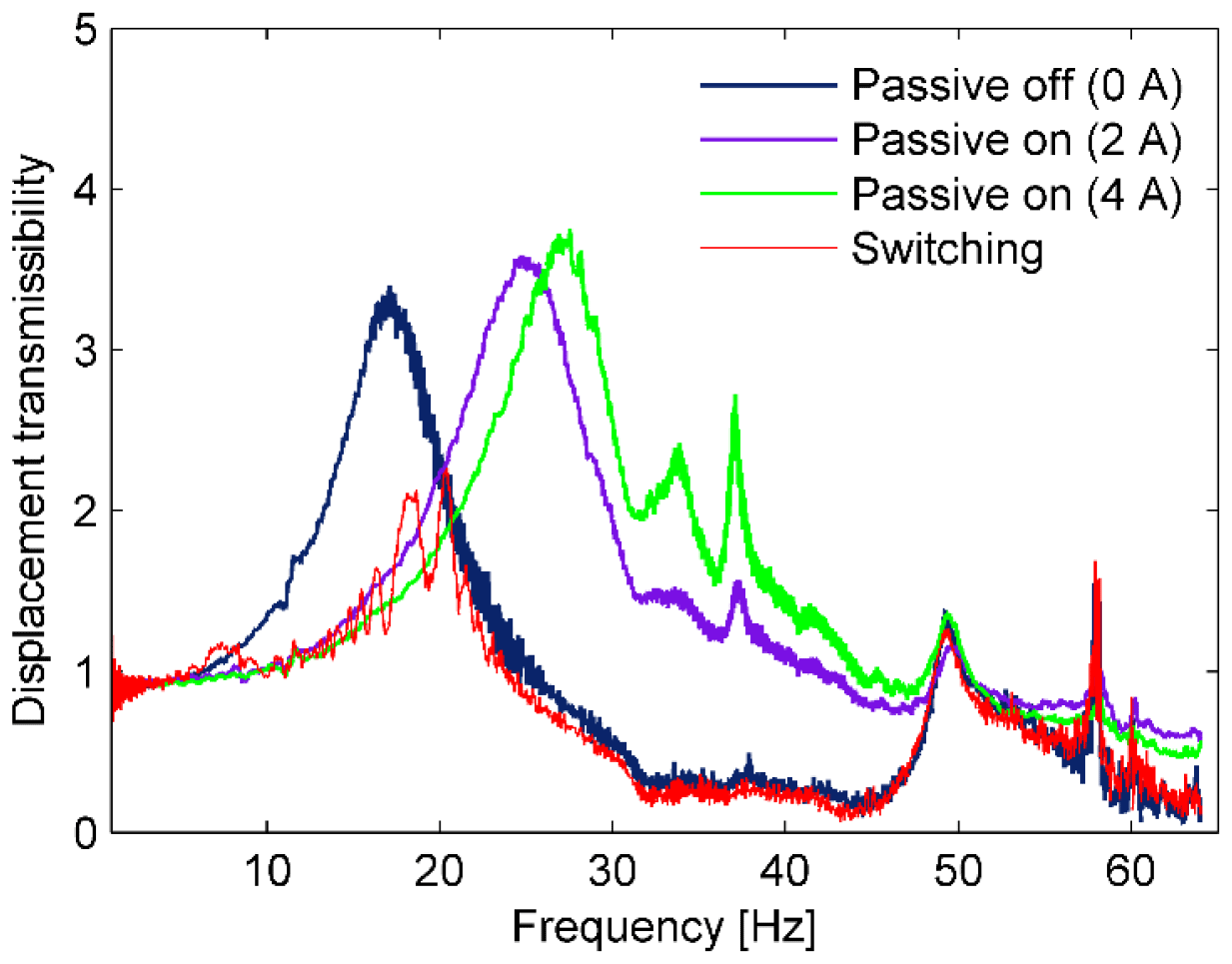
Figure 2Displacement transmissibility response of the semiactive suspension system in the frequency domain.
Table 1The parameters of the quarter-car suspension system based on the bench-scale model (Sun et al., 2015; Sistla et al., 2020; Pan et al., 2015; Pusadkar et al., 2018).

In a small car, the natural frequency of the suspension is about 2 to 3 Hz, and the maximum displacement lies between 50 and 80 mm, while the maximum displacement of the developed system is 2 mm. Therefore, the values of the natural and excitation frequencies in the model were shifted about 5 times higher than those in the actual car according to the scaling law, while keeping the acceleration at the same level in both systems. The natural frequency was increased on the basis of the nominal stiffness of the MRE-based isolator, K1. All variables and dimensions were also scaled as shown in Table 2 (Mills, 1979; and Yang et al., 2016).
Experimental results are shown in Figs. 2 and 3. Figure 2 represents the transmissibility response of the sprung mass in the frequency domain, with the fixed current values of 0, 2, and 4 A, and the switching mode. The proposed suspension system has two natural frequencies, as shown in Fig. 2. The first natural frequency is tunable from 17 to 29 Hz by applying an appropriate current. The first natural frequency values were found to be 17, 25, and 29 Hz, corresponding to the applied current values of 0, 2, and 4 A, respectively. The second natural frequency appeared at 50 Hz. The influence of the second natural frequency is small and not tunable. In the case of the current switching, the current applied to the absorber was set to 4 and 0 A as the suspension works in low-frequency and high-frequency ranges, respectively. Furthermore, the vibration isolation performance was improved remarkably by using the switching mode. The transmissibility indicates that the resonance phenomenon of the vibration response could be avoided by isolating the natural frequency from the disturbance frequency. This fact is illustrated by a comparison of the time history, as seen in Fig. 3, showing that the response amplitudes are minimized consistently by switching the applied current to the absorber. The drawback of the switching mode is that the disturbance frequency must be known in advance. A control algorithm scheme is developed in the next section to achieve an effective vibration suppression in the case of disturbance with unknown frequency.
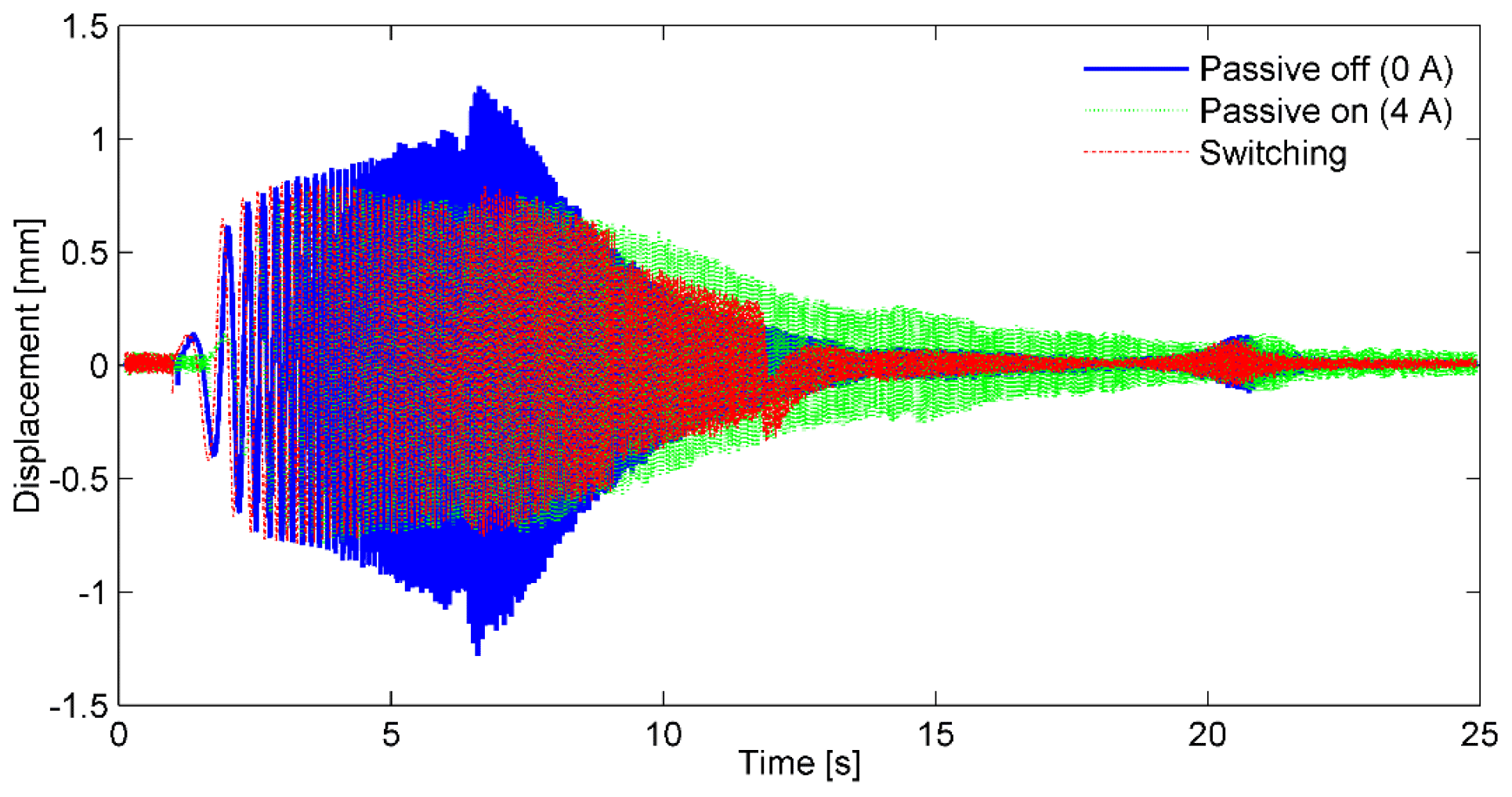
Figure 3Displacement response of the sprung mass under swept-sine excitation where frequency changed from 1 to 64 Hz.
The excitation frequency is generally unknown for its bump and random excitations. We developed a novel controller for the MRE-based absorber so that the suspension works effectively in these cases. The controller was developed in accordance with the physical characteristics such as the uncertain system parameters, small control force property, and actuator constraint.
3.1 A quarter-car suspension model
As shown in Fig. 1, the variables, xr, xu, and xs, represent road disturbance, wheel displacement, and car body, respectively. The MRE-based absorber produces a force FMRE.
The dynamic equations of the suspension system can be expressed as follows:
By defining the state variables as , where x1=xs, , x3=xu, and , the sprung mass dynamics can be simplified to the following:
where
and
The force FMRE can be determined by using the numerical model of MRE developed in our previous research (Nguyen et al., 2018a). The model was used to design a suspension system in which the material properties consists of three components, namely the viscosity, magnetism, and friction. The force FMRE generated by the absorber is calculated as follows:
where
and
In Eqs. (8a), (8b), and (8c), the viscoelastic force Fv is presented in a , where K and x are the stiffness constant and displacement, and C and x1 are the viscosity constant and displacement of the viscous component. The magnetic force Fm represents the interaction of the magnetic dipoles in shear deformation, where Km is the tunable stiffness. The friction force Ff represents the Coulomb friction, where Ffs and xs are the force and displacement at static equilibrium. Ffmax and x2 are the maximum friction and the displacement for reaching , as a function of displacements. Note that, when the applied current increases, the Fm and Ff components increase significantly, while the component Fv is almost unchanged. The absorber force increases as the applied current increases and reaches a maximum value at 4 A. The parameters of the model are determined based on the proposal in Nguyen et al. (2018a), as listed in Table 1.
3.2 Input constraint of the controller
In the active control, the control force can be generated at any quadrant in the force–displacement diagram. However, in the MRE-based absorber, the force can only be activated during operation within the first and third quadrants while the absorber works as a passive device in the remaining two quadrants. The force constraint, FMRE generated by the absorber, is limited compared to the requirement of the controller, Fc as follows:
In Eq. (9), Fc is the desired force determined by the control algorithm, Fpas is the passive force generated in the absorber without an electric current, and x is the displacement of the absorber. Furthermore, the force that the MRE-based absorber can generate is bounded by the upper and lower limit values. |Fmax(t)| and |Fpas(t)| are the magnitudes of the maximum and passive absorber forces corresponding to the cases where maximum and no current applied, respectively. If the control force Fc(t) falls within the range, i.e., , the inverse model is used to calculate the optimal desired input current. Otherwise, the input current should be set at either zero or the maximum achievable level.
Remark 1. If the control force, FMRE, satisfies the actuator constraint described by Eq. (9), the inverse model is responsible for converting the control force into the current applied to the absorber in the real application (Nguyen et al., 2018a). The current is determined as follows:
where
The definition of variables in Eqs. (11a) to (11c) is the same as in Eqs. (8a) to (8c).
The following assumptions are essential to the subsequent controller designs.
- A1.
The state variable vector x(t) is a measurable signal.
- A2.
The function g is unknown and bounded.
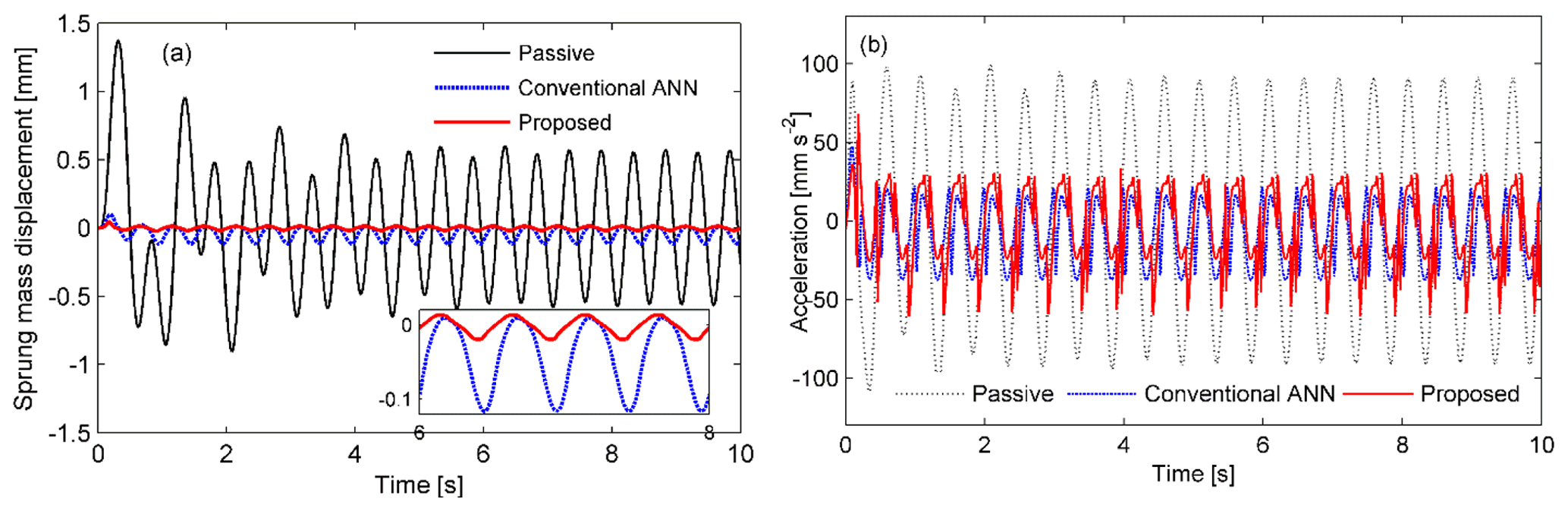
Figure 4Comparison of the responses of the sprung mass ms. (a) Displacement response. (b) Acceleration.
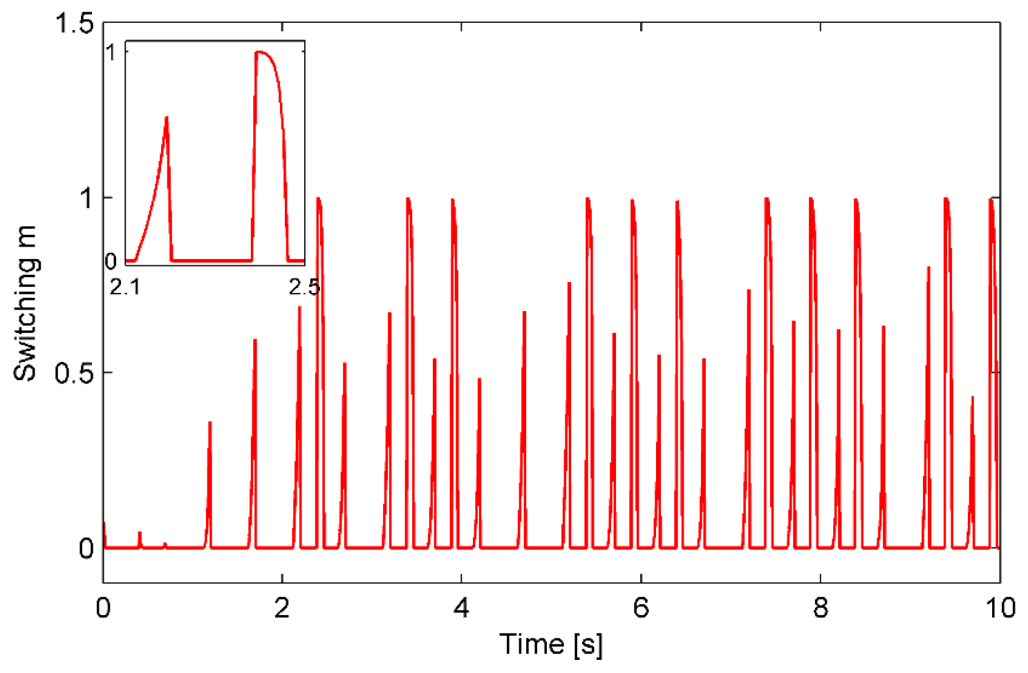
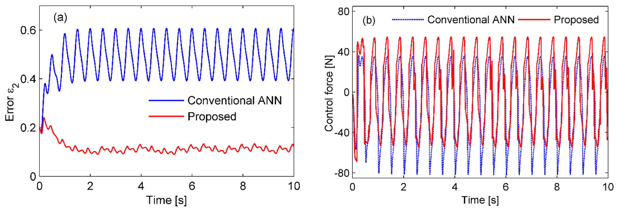
Figure 6Time histories of the approximation error ε2 and the control force Fc. (a) The errors are compared for the conventional and proposed controllers and (b) the corresponding force histories.
3.3 Problem statement
Lemma 1. Let f(x) be a continuous function on compact set D, with an arbitrary accuracy ε. Consider the radial basis function (RBF) neural network (collectively RBFNN) WTz(x) that can approximate f(x) such that, in the following:
where is an optimal weight vector, N>1 is the number of the neurons, is the vector representation of the RBF, ε is the corresponding approximation error, and D represents the region of active neurons for f(x), defined by the following:
The output is in the active region D at all times. The weight vector W is updated so as to minimize ε on the compact set D, as follows:
assuming that ε is bounded by with ε∗ being an unknown positive constant. The Gaussian function, zi(x), is given by the following:
where ωi and ηi represent the width and center of the function, respectively.
Now, the following additional assumption is considered:
- A3.
All the optimal weight vectors are bounded, i.e., , and are unknown positive constants.
The Lyapunov candidate function V(t) is chosen and its derivative function has the following form:
In Eq. (13), k>0 and c>0. By multiplying both sides of the inequality by ekt, and also by integrating over [0, t], the expression is rewritten as follows:
Apparently, V(t) is bounded for when . As a result, the variables in the Lyapunov function are bounded directly by known constants.
Lemma 2. For any ϵ>0 and also for any η∈R, the following inequality is introduced (Polycarpou et al., 1996):
where κ is the constant, κ=0.2785. The function tanh (⋅) has advantages over sat (⋅) in the robust control because the higher order terms should be considered in nonlinear feedback control systems.
Remark 2. In an adaptive controller, the value of the function g is approximated, and the value does not necessarily fall inside the compact set Di due to external disturbances or inappropriate controller initialization. The general-type adaptive neural network controller ensures only the semiglobally uniformly ultimately bounded (SGUUB) tracking stability. Recently, the global tracking control was resolved by adopting the indirect ANN in which a switching function was used (Wu et al., 2013; Huang et al., 2012). In this paper, the novel control scheme is developed for obtaining the globally ultimately bounded (GUUB). The control output, u(t), consists of three components, as follows:
where uad(t) is the output of the conventional adaptive neural network controller, ur(t) the output of the robust controller, which plays a role in controlling system outside the active domain, and m(t) is a smooth function to switch the authority between the above two controllers, uad(t) and ur(t), respectively.
The switching function is introduced as follows:
In Eq. (20), ωk and b≥1 are the gradient and order of the function, are positive constants, and r1 corresponds to the radius of the compact set Di. The switching (Eq. 20) allows the controller to eliminate the contribution of ur from the neural region, and thus, the amount of computation will be significantly reduced.
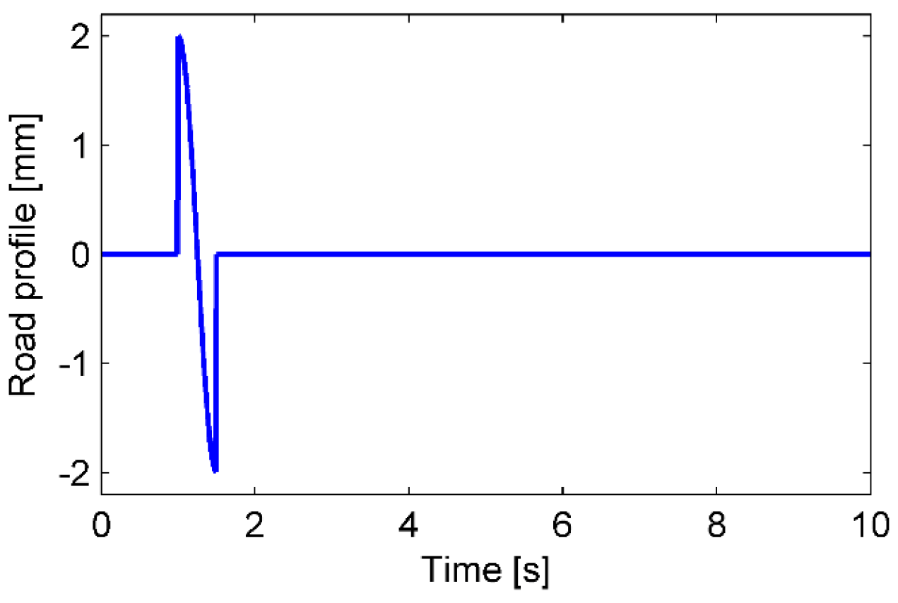
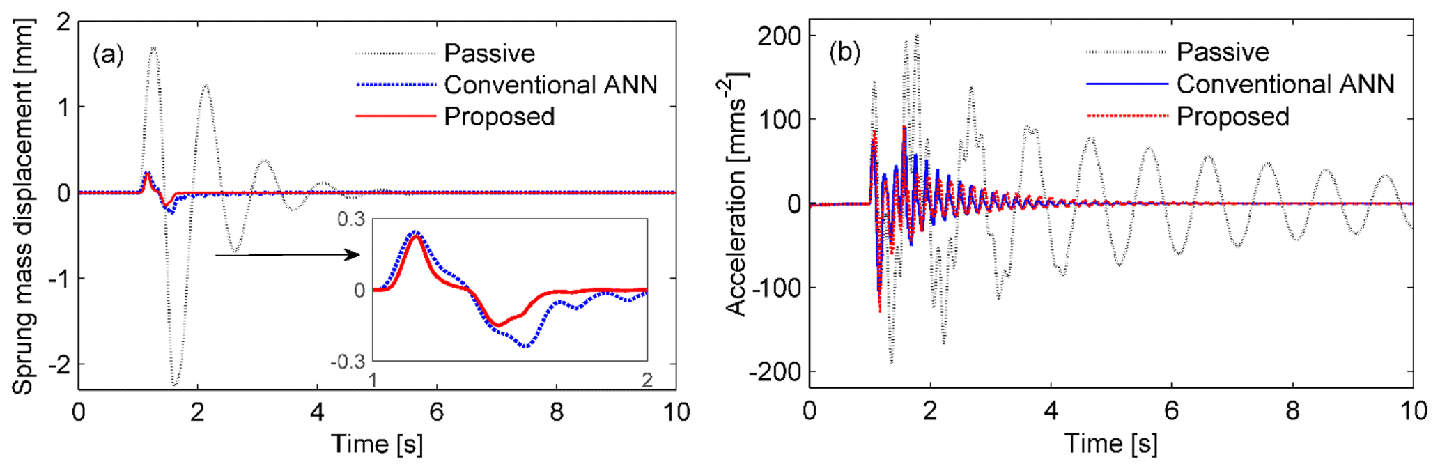
Figure 8Comparison of the responses of the sprung mass ms in the case of a bump excitation. (a) Displacement response. (b) Acceleration.
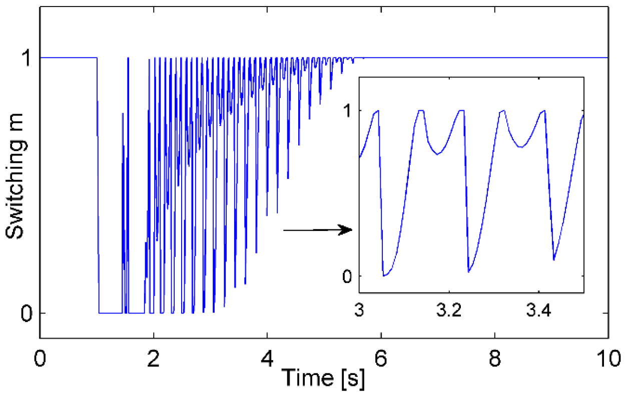
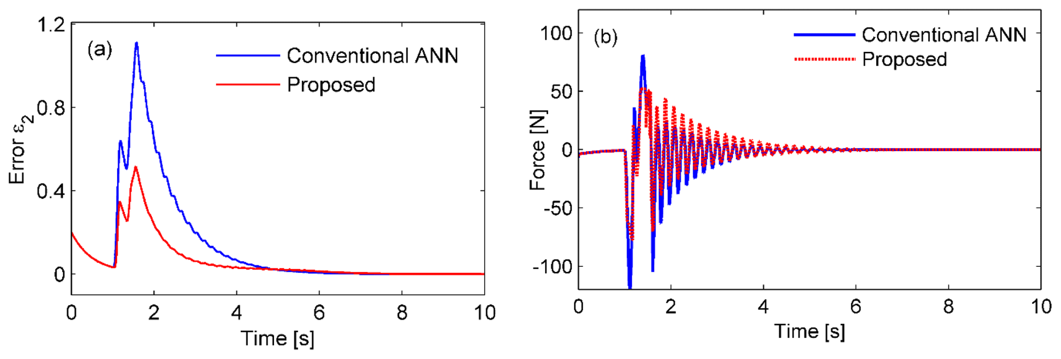
Figure 10Time histories of the approximation error ε2 and the control force Fc in the case of a bump excitation. (a) The errors are compared for the conventional and proposed controllers and (b) the corresponding force histories.
First of all, we define the tracking error as z1=x1 and also the second error term as or . From Eq. (3), we have the tracking error dynamic equation as follows:
For the ANN controller design, we follow the two steps as shown below.
Step 1. A virtual control target value α1 is exploited.
Let k1 be the gain coefficient; therefore, we write . The time derivative of the tracking error is written as follows:
Next, we consider the Lyapunov function, , which is expressed explicitly as follows:
Step 2. The actual control scheme is proposed in this step. In this step, the auxiliary design system and the switching function are crucial for this controller.
The time derivative of the second error variable is as follows: . The tracking error dynamics in Eq. (21) can be rewritten for Fc as follows:
In Eq. (21), , where Fc is the desired control force and FMRE is the force constraint present in the MRE-based absorber as defined by Eq. (9). In addition, , μ is a small positive value, and ξ∈R is an auxiliary design system state. The following auxiliary design system is proposed in order to express the effects of the actuator constraint:
By employing an RBFNN, as declared in Lemma 1, the approximation is defined as follows:
For the proposed controller, the control force can be expressed, using Eqs. (19) and (20), as follows:
where
and
The function uad in Eq. (28) represents the output of the conventional ANN controller as the main controller that works in the active region of neurons, and ur in Eq. (29) is the output of the robust controller as the compensatory controller working outside the neural approximation region. The switching function m monitors whether the signal is inside or outside the active region and switches the authority between the above two controllers.
Again, we consider the Lyapunov function V2 as follows:
By applying Lemma 2, the time derivative of V2 will then be the following:
where ϵ is a positive constant and κ=0.2785, .
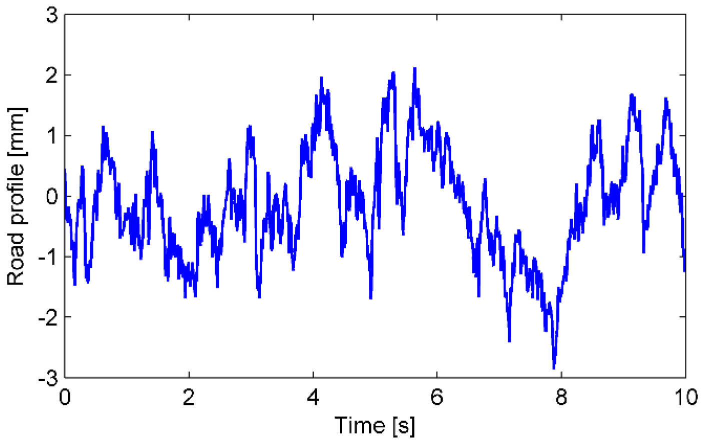
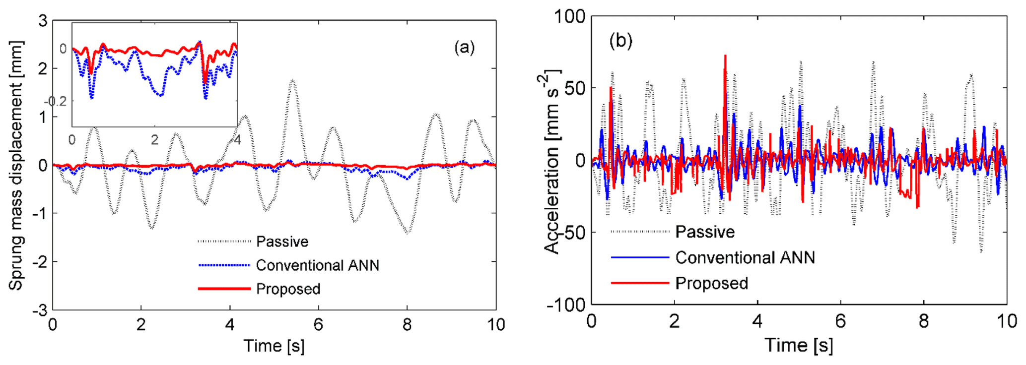
Figure 12Comparison of the response of the sprung mass ms in the case of a random excitation. (a) Displacement response. (b) Acceleration.
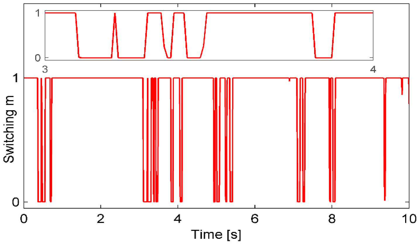
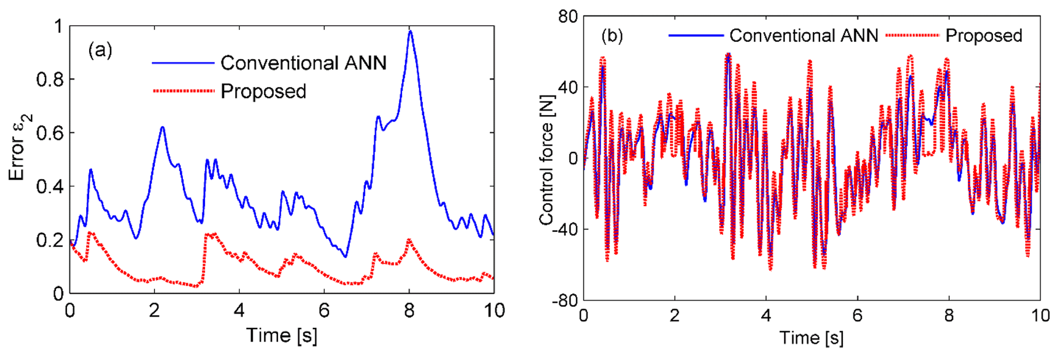
Figure 14Time histories of the approximation error ε2 and the control force Fc in the case of a random excitation. (a) The errors are compared for the conventional and proposed controllers and (b) the corresponding force histories.
By using the control algorithm as described by Eq. (27), Eq. (31) is rewritten as follows:
where .
The derivative of the Lyapunov function, Eq. (32), is divided into three parts, namely , where each term on the right-hand side of the inequality is written explicitly as follows:
Assuming that , and denote the estimation errors, we obtain the following:
In Eq. (35), the inequality of holds, as defined in Eq. (26).
We consider the stability of the system due to the influence of unknown bounded , , and the adaptive weight vector . The Lyapunov function is extended as follows:
The updated laws are proposed as follows:
Applying the Schwartz inequality, we have the following:
By using Eqs. (37) and (38), Eq. (36b) becomes the following:
For Eq. (39), the following were defined:
It follows that all the signals, including , and , are uniformly bounded. Consequently, are bounded for Wc(t), ε2(t). Then, uad and ur are bounded, as shown by Eqs. (28) and (29). In addition, α1 and x2 are bounded since and . Finally, the function and the control force Fc are also bounded, as shown by Eqs. (26) and (28).
On the other hand, the following is deduced from Eq. (39):
which implies that the displacement z1=x1 will eventually converge to the following:
5.1 Simulation results
Performances of three types of controllers were compared, namely the passive controller, the conventional adaptive neural network controller (conventional ANN), and the proposed adaptive neural global controller. Three typical cases were analyzed to evaluate the effectiveness of the proposed controller. The parameters of the quarter-car model used in the simulations are listed in Table 1. The parameters of the controller used in the simulations are summarized as , , Γ=0.5, and Kλ=0.2.
5.1.1 Simulation case 1: a periodic disturbance
The road profile is defined as a periodic disturbance signal given by xr1(t)=2sin (4πt) (in millimeters). The performances of the passive control, conventional ANN, and proposed controller are compared for sinusoidal excitation. The responses of the suspension system to the excitation are shown in Fig. 4. The sprung mass displacement response is remarkably reduced in the case of using an MRE-based absorber in comparison to the passive control. In the semiactive suspension system, it is clearly seen that the proposed controller performs more effectively than the conventional ANN. The sprung mass absolute acceleration response is significantly suppressed for both controllers (Fig. 4b). The conventional ANN performs slightly better than the proposed controller. The histories of the switching signal m are shown in Fig. 5. The corresponding histories of the control force and error ε2 are also shown in Fig. 6. In the proposed controller, the switching signal responses are changed from 0 to 1 to exchange control authority between the conventional ANN and robust controller. Therefore, the error ε2 defined in Eq. (12) reduced significantly in the case of the proposed controller, as shown in Fig. 6a.
The control forces are compared for two algorithms, as shown in Fig. 6b. The conventional ANN controller required the larger control force, with a maximal value of 80 N, while the proposed controller needed a maximal value of 60 N.
5.1.2 Simulation case 2: a bump excitation
Assuming that the road surface is smooth, sinusoidal bump excitation is considered, as depicted in Fig. 7. The maximum responses of the sprung mass displacement and acceleration were found to decrease significantly by using the MRE-based absorber compared to the passive one. The maximum displacement values were 0.25 and 0.27 mm for the proposed and conventional controllers, respectively. The values are remarkably lower than 2.2 mm, which was observed in the passive system as shown in Fig. 8b. The corresponding approximation errors and control forces for both controllers are shown in Fig. 10. For the proposed controller, the error value is significantly smaller at the time of the bump and converges to zero faster than that of the conventional controller. Furthermore, the force value is also smaller in the case of the proposed controller. By using the proposed algorithm, the involvement of the conventional ANN controller and robust controller could be changed more efficiently in response to the switching signal shown in Fig. 9.

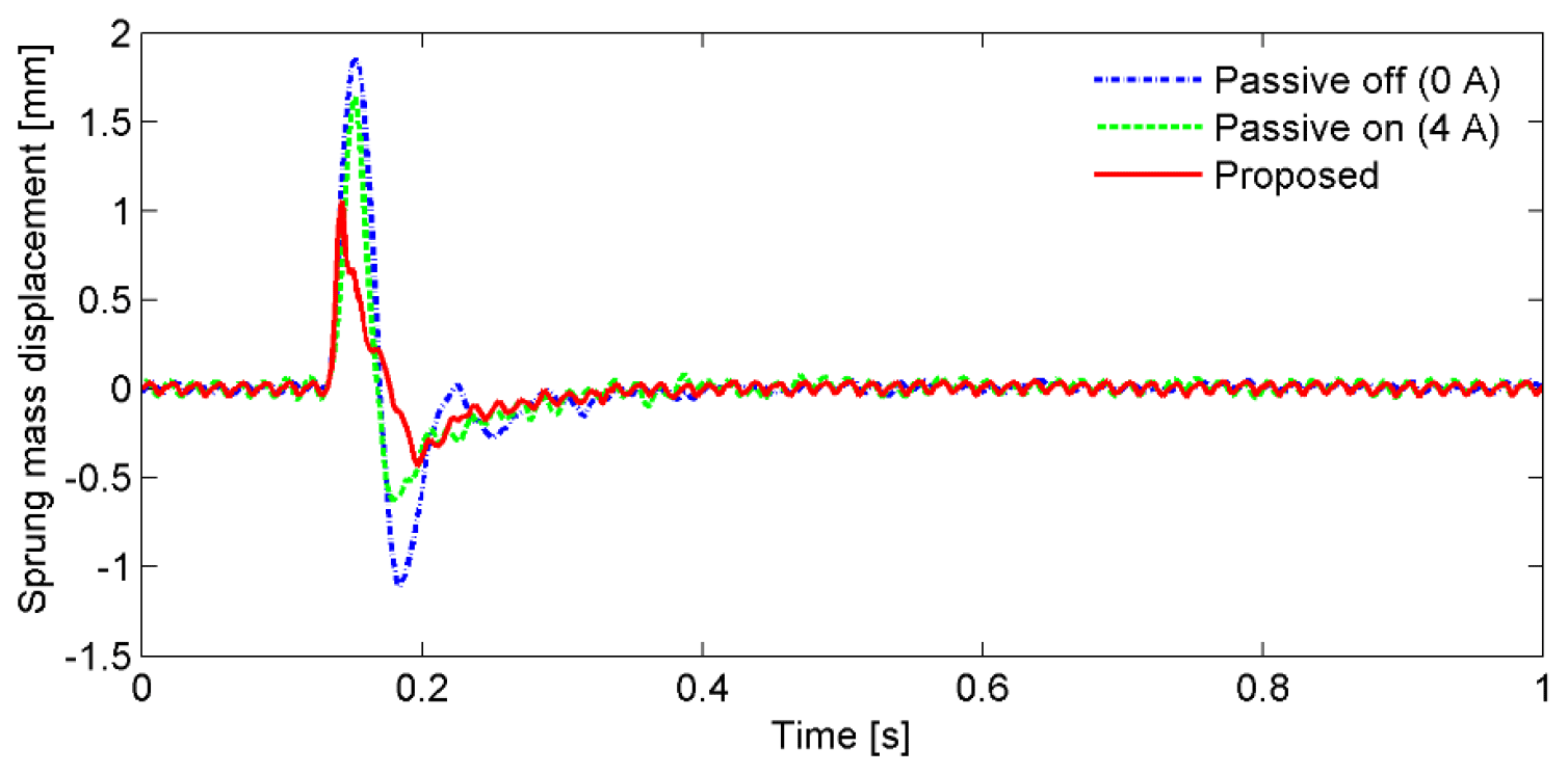
Figure 16Displacement responses of the sprung mass that were measured for the pulse excitation.
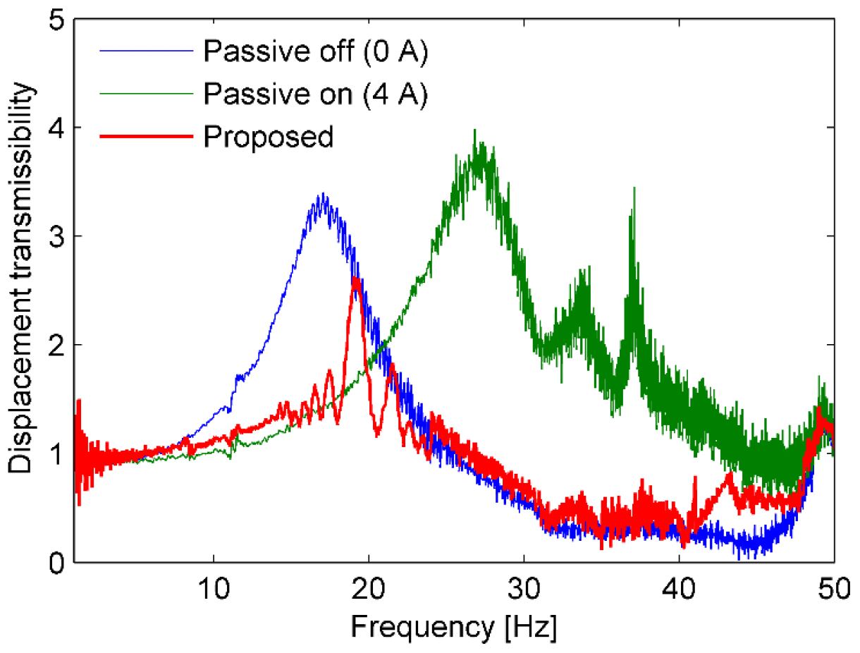
Figure 17Displacement transmissibility responses of the scaled suspension plant that were measured for the random disturbance.
Table 3Displacement and acceleration values of the sprung mass response for different excitations (simulations).
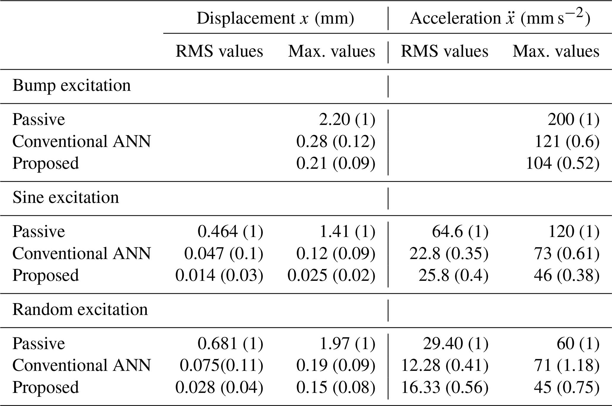
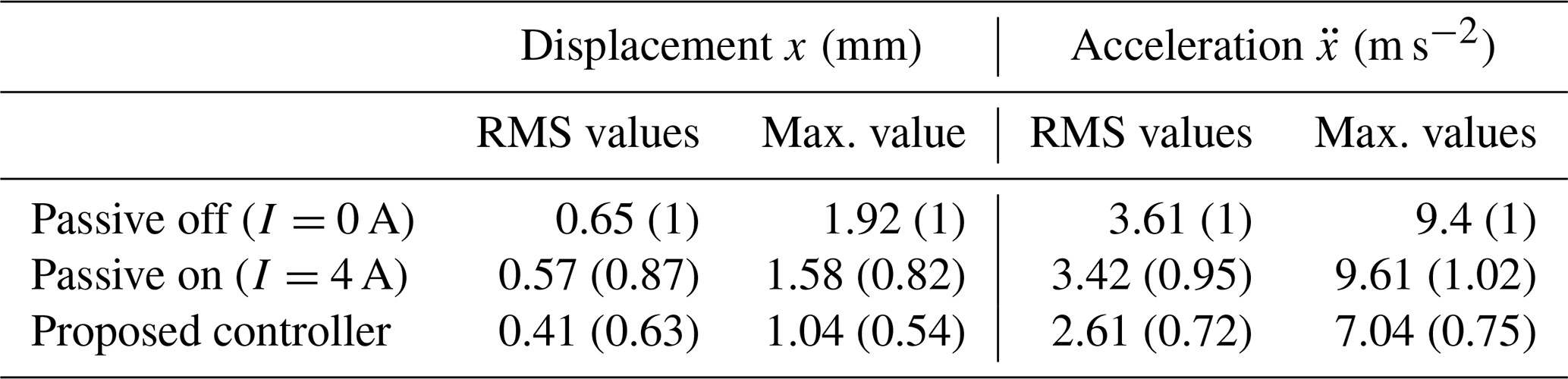
Table 4Displacement and acceleration values of the sprung mass response for the random excitations (experiments).
5.1.3 Simulation case 3: a random excitation
We further analyzed the case of a random excitation given according to the displacement power spectral density. The excitation displacement is obtained by integrating white noise in the time domain (Tyan et al., 2009), as shown in Fig. 11. The responses are shown in Figs. 12 to 14. Figure 12 shows the time histories of the sprung mass responses, Fig. 13 shows the histories of the switching response, and Fig. 14 shows the approximation error and the force responses. It is evident that the displacement, acceleration, error, and force responses are remarkably suppressed in the case of the proposed controller. The results indicate that the proposed controller achieves the better performance than the conventional ANN.
From three cases of excitation, we can conclude that the proposed controller achieves better steady-state tracking accuracy, faster response, and lower control force via switching between the conventional ANN and the robust controller, as evidenced by the switching signal.
In the simulation, the displacement and acceleration values of the sprung mass response are listed in Table 3. The effectiveness of the proposed controller is compared with other controllers in three cases, namely bump excitation, sine excitation, and random excitation. The values in parentheses represent the ratio of the values to those obtained for the passive off. By using the proposed controller, the root mean square (RMS) ratios of the unsprung displacement decreased significantly to 0.03 and 0.04 for sine excitation and random excitation, respectively. Furthermore, the acceleration RMS values also decreased in the case of using the controller. The conventional ANN scheme performed slightly better than the proposed algorithm; the RMS ratios were 0.41 and 0.56 for the conventional and proposed controllers, respectively. The maximum displacement and acceleration responses when using the controllers were much smaller than the responses of the passive control cases. However, the RMS value in the case of the proposed controllers was higher than in the case of the conventional controller.
5.2 Experiment results
The experimental setup, with the aim to evaluate the effectiveness of the proposed semiactive suspension and controller, is shown in Fig. 15a. The photo of the system is also shown in Fig. 15b. Laser displacement sensors (Keyence Corporation; LB-02) were used to measure the base, unsprung mass, and sprung mass displacements. The displacement responses were processed by the FFT analyzer (Ono Sokki; CF-6400). The analog displacement signals were sent to a real-time embedded device (National Instruments; myRIO) as the input signal. The proposed control scheme was embedded in the device by using the Laboratory Virtual Instrument Engineering Workbench (LabVIEW) programming. The device determined the analog signal to drive the direct current (DC) power supply. A DC power supply (Matsusada Precision Inc.; series POP 65-5) provided the current to the absorber to obtain the desired control force.
The experimental results are shown in Figs. 16 to 18. The result of the proposed system was compared with those of the passive systems. Figure 17 shows the displacement transmissibility of the sprung mass for the random disturbance. The transmissibly of the passive systems is almost the same as in the case of the swept-sine excitation. Although the excitation frequency is unknown, the transmissibility was decreased significantly by the proposed controller. The displacement response remarkably reduced when using the controller in the case of the pulse and random excitation, as shown in Figs. 16 and 18, respectively. In detail, the displacement and acceleration values for random excitation are listed in Table 4. The ratio values were presented in parentheses compared to the passive off case. The RMS of the sprung displacement and acceleration values were reduced by 37 % and 28 %, respectively. The maximum values were also reduced by 46 % and 25 %, respectively, for the displacement and acceleration.

Figure 18Displacement responses of the sprung mass that were measured for the random disturbance. (a) Passive off (0 A). (b) Passive on (4 A). (c) The proposed controller.
In this study, a novel semiactive suspension and an adaptive neural network controller for an uncertain suspension system, using an MRE-based absorber, were proposed. The suspension can tune its own natural frequency in a wide frequency range. The NN is used to approximate the uncertain dynamics in order to reduce the number of adaptive parameters and to avoid the control singularity problem. The system stability was examined according to the Lyapunov theory. The switching algorithm was used to effectively adjust the ANN controller and also to ensure the GUUB stability at the same time. Moreover, the input constraint problem is better handled according to the state of an auxiliary design system. The performance of the controller was evaluated by numerical simulations and experiments under different excitations. The proposed controller could overcome the drawbacks that exist in the conventional semiactive system, including global stability, uncertain parameter, input constraint, and low control force.
All data included in this study are available upon request from the corresponding author.
XBN and TK conceived the idea, developed the theory, performed experiments and simulations, and analyzed the results. XBN wrote the paper, TK corrected the paper, and both acted as corresponding authors. HTT helped to evaluate the idea, engaged in discussions with the corresponding authors regarding the outcome, and assisted with the editing of the paper.
The authors declare that they have no conflict of interest.
This research is funded by Funds for Science and Technology Development of the University of Danang under project number B2019-DN06-16.
This research is funded by Funds for Science and Technology Development of the University of Danang under project number B2019-DN06-16.
This paper was edited by Dario Richiedei and reviewed by two anonymous referees.
Cao, J., Liu, H., Li, P., and Brown, D. J.: State of the art in vehicle active suspension adaptive control systems based on intelligent methodologies, IEEE T. Intell. Transp., 9, 392–405, https://doi.org/10.1109/TITS.2008.928244, 2008.
Chen, M., Ge, S. S., and Ren, B.: Adaptive tracking control of uncertain MIMO nonlinear systems with input constraints, Automatica, 47, 452–465, https://doi.org/10.1016/j.automatica.2011.01.025, 2011.
Choi, S. B., Li, W., Yu, M., Du, H., Fu, J., and Phu, D. X.: State of the Art on Control Schemes for Smart Systems Featuring Magneto-Rheological Materials, Smart Mater. Struct., 25, 043001, https://doi.org/10.1088/0964-1726/25/4/043001, 2016.
Eem, S. H., Jung, H. J., and Koo, J. H.: Modeling of magneto-rheological elastomers for harmonic shear deformation, IEEE T. Magn., 48, 3080–3083, https://doi.org/10.1109/TMAG.2012.2205140, 2012.
El Majdoub, K., Ghani, D., Giri, F., and Chaoui, F. Z.: Adaptive semi-active suspension of quarter-vehicle with magnetorheological damper, J. Dyn. Syst-T. ASME, 137, 021010, https://doi.org/10.1115/1.4028314, 2015.
Fallah, A. Y. and Taghikhany, T.: Sliding mode fault detection and fault tolerant control of smart dampers in semi-active control of building structures, Smart Mater. Struct., 24, 125032, https://doi.org/10.1088/0964-1726/24/12/125030, 2015.
Fei, J. and Xin, M.: Robust adaptive sliding mode controller for semi-active vehicle suspension system, Int. J. Innov. Comput. I., 8, 691–700, 2012.
Gong, X. L., Zhang, X. Z., and Zhang, P. Q.: Fabrication and characterization of isotropic magnetorheological elastomers, Polym. Test., 24, 669–676, https://doi.org/10.1016/j.polymertesting.2005.03.015, 2005.
He, W., Dong, Y., and Sun, C.: Adaptive neural impedance control of a robotic manipulator with input saturation, IEEE T. Syst. Man. Cy-S., 46, 334–344, https://doi.org/10.1109/TSMC.2015.2429555, 2016.
Huang, J. T.: Global tracking control of strict-feedback systems using neural network, IEEE T. Neur. Net. Learn., 23, 1714–1725, https://doi.org/10.1109/TNNLS.2012.2213305, 2012.
Jansen, L. M. and Dyke, S. J.: Semi-active control strategies for MR dampers: A comparative study, J. Eng. Mech-ASCE, 126, 795–803, https://doi.org/10.1061/(ASCE)0733-9399(2000)126:8(795), 2000.
Komatsuzaki, T., Inoue, T., and Terashima, O.: Broadband vibration control of a structure by using a magnetorheological elastomer-based tuned dynamic absorber, Mechatronics, 40, 128–136, https://doi.org/10.1016/j.mechatronics.2016.09.006, 2016.
Li, H., Liu, H., Gao, H., and Shi, P.: Reliable fuzzy control for active suspension systems with actuator delay and fault, IEEE T. Fuzzy Syst., 20, 342–357, https://doi.org/10.1109/TFUZZ.2011.2174244, 2012.
Li, H., Jing, X., and Karimi, H. R.: Output-feedback based H∞ control for active suspension systems with control delay, IEEE T. Ind. Electron., 61, 436–446, https://doi.org/10.1109/TIE.2013.2242418, 2014.
Li, W. H., Zhou, Y., and Tian, T. F.: Viscoelastic of MR elastomers under harmonic loading, Rheol. Acta., 49, 733–740, https://doi.org/10.1007/s00397-010-0446-9, 2010.
Liao, G. J., Gong, X. L., Kang, C. J., and Xuan, S. H.: The design of an active-adaptive tuned vibration absorber based on magnetorheological elastomer and its vibration attenuation performance, Smart Mater. Struct., 20, 5015–5025, https://doi.org/10.1088/0964-1726/20/7/075015, 2011.
Mills, R. S.: Model Test on Earthquake Simulators: Development and Implementation of Experimental Procedures, PhD Thesis Stanford Univ., CA, 1979.
Nguyen, S. D., Kim, W., Park, J., and Choi, S. B.: A new fuzzy sliding mode controller for vibration control systems using integrated structure smart dampers, Smart Mater. Struct., 26, 045038, https://doi.org/10.1088/1361-665X/aa52fd, 2017a.
Nguyen, X. B., Komatsuzaki, T., Iwata, T., and Asanuma, H.: Fuzzy semi-active vibration control of structures using magnetorheological elastomer, Shock. Vib., 2017, 3651057, https://doi.org/10.1155/2017/3651057, 2017b.
Nguyen, X. B., Komatsuzaki, T., Iwata, Y., and Asanuma, H.: Modeling and semi-active fuzzy control of magnetorheological elastomer-based isolator for seismic response reduction, Mech. Syst. Signal Pr., 101, 449–466, https://doi.org/10.1016/j.ymssp.2017.08.040, 2018a.
Nguyen, X. B., Komatsuzaki, T., Iwata, Y., and Asanuma, H.: Robust adaptive controller for semi-active control of uncertain structures using a magnetorheological elastomer-based isolator, J. Sound Vib., 434, 192–212, https://doi.org/10.1016/j.jsv.2018.07.047, 2018b.
Nguyen, X. B., Komatsuzaki, T., and Zhang, N.: A nonlinear magnetorheological elastomer model based on fractional viscoelasticity, magnetic dipole interactions, and adaptive smooth Coulomb friction, Mech. Syst. Signal Pr., 141, 106438, https://doi.org/10.1016/j.ymssp.2019.106438, 2020.
Nie, S., Zhuang, Y., Liu, W., and Chen, F.: A semi-active suspension control algorithm for vehicle comprehensive vertical dynamics performance, Vehicle Syst. Dyn., 55, 1099–1122, https://doi.org/10.1080/00423114.2017.1299871, 2017.
Norouzi, M., Alehashem, S. M. S., Vatandoost, H., Ni, Y. Q., and Shahmardan, M. M.: A new approach for modeling of magnetorheological elastomers, J. Intel. Mat. Syst. Str., 27, 1121–1135, https://doi.org/10.1177/1045389X15615966, 2016.
Pan, H., Sun, W., Gao, H., and Yu, J.: Finite-Time Stabilization for Vehicle Active Suspension Systems With Hard Constraints, IEEE T. Intell. Transp., 16, 2663–2672, https://doi.org/10.1109/TITS.2015.2414657, 2015.
Phu, D. X., Shah, K., and Choi, S. B.: Design of a new adaptive fuzzy controller and its implementation for the damping force control of a magnetorheological damper, Smart Mater. Struct., 23, 065012, https://doi.org/10.1088/0964-1726/23/6/065012, 2014.
Polycarpou, M. M.: Stable adaptive neural control scheme for nonlinear systems, IEEE T. Automat. Contr., 41, 447–451, https://doi.org/10.1109/9.486648, 1996.
Pusadkar, U. S., Chaudhari, S. D, Shendge, P. D., and Phadke, S.B.: Linear disturbance observer based sliding mode control for active suspension systems with non-ideal actuator, J. Sound Vib., 442, 428-44, https://doi.org/10.1016/j.jsv.2018.11.003, 2018.
Sistla, P., Figarado, S., Chemmangat, K., Manjarekar, N. S., and Valappil, G. K.: Design and performance comparison of interconnection and damping assignment passivity-based control for vibration suppression in active suspension systems, J. Vib. Control, 26, 1–19, https://doi.org/10.1177/1077546320933749, 2020.
Sun, W., Gao, H., and Kaynak, O.: Adaptive Backstepping Control for Active Suspension Systems With Hard Constraints, IEEE-ASME T. Mech., 18, 1072–1079, https://doi.org/10.1109/TMECH.2012.2204765, 2013.
Sun, W., Gao, H., and Kaynak, O.: Vibration isolation for active suspensions with performance constraints and actuator saturation, IEEE-ASME T. Mech., 20, 675–683, https://doi.org/10.1109/TMECH.2014.2319355, 2015.
Tyan, F., Hong, Y. F., Tu, S. H., and Jeng, W. S.: Generation of random road profiles, Journal of Advanced Engineering, 4, 1373–1378, 2009.
Wu, J., Chen, W., Zhao, D., and Li, J.: Globally stable direct adaptive backstepping NN control for uncertain nonlinear strict-feedback systems, Neurocomputing, 122, 134–147, https://doi.org/10.1016/j.neucom.2013.05.042, 2013.
Yagiz, N. and Hacioglu, Y.: Backstepping control of a vehicle with active suspensions, Control Eng. Pract., 16, 1457–1467, https://doi.org/10.1016/j.conengprac.2008.04.003, 2008.
Yang, J., Du, H., Li, W., Li, Y., Li, J., Sun, S., and Deng, H. X.: Experimental study and modeling of a novel magnetorheological elastomer isolator, Smart Mater. Struct., 22, 1–14, https://doi.org/10.1088/0964-1726/22/11/117001, 2013.
Yang, J., Sun, S., Tian, T., Li, W., Du, H., Alici, G., and Nakano, M.: Development of a novel multi-layer MRE isolator for suppression of building vibrations under seismic, Mech. Syst. Signal Pr., 70/71, 811–820, https://doi.org/10.1016/j.ymssp.2015.08.022, 2016.
Zhang, T., Ge, S. S., and Hang, C. C.: Adaptive neural network control for strict-feedback nonlinear systems using backstepping design, Automatica, 36, 1835–1846, https://doi.org/10.1016/S0005-1098(00)00116-3, 2000.
Zhang, X., Peng, S., Wen, W., and Li, W.: Analysis and fabrication of patterned magnetorheological elastomers, Smart Mater. Struct., 17, 045001, https://doi.org/10.1088/0964-1726/17/4/045001, 2008.
Zhu, W. and Rui, X. T.: Semiactive Vibration Control Using a Magnetorheological damper and a magnetorheological elastomer based on the Bouc-Wen model, Shock. Vib., 2014, 405421, https://doi.org/10.1155/2014/405421, 2014.
- Abstract
- Introduction
- A novel semiactive suspension system using an MRE-based absorber
- Problem formulation
- Adaptive neural network (ANN) controller design
- Simulation and experiment results
- Conclusions
- Data availability
- Author contributions
- Competing interests
- Acknowledgements
- Financial support
- Review statement
- References