the Creative Commons Attribution 4.0 License.
the Creative Commons Attribution 4.0 License.
 | 06 Nov 2020
Design and evaluation of a hybrid passive–active knee prosthesis on energy consumption
Xiaoming Wang
Qiaoling Meng
Zhewen Zhang
Jinyue Sun
Jie Yang
Hongliu Yu
The existing lower limb prostheses with passive knees have disadvantages, causing an asymmetric gait and higher metabolic cost during level walking which is in contrast with a normal gait. However, most existing active knee prostheses need a significant amount of energy. In this paper, a novel hybrid passive–active knee prosthesis (HPAK) that allows passive and active operating modes is proposed, which contains an active motor unit and a novel hydraulic damper with an electrically controlled valve that adjusts the damping torque dynamically during each gait cycle. An energy consumption model was built to evaluate the energy consumption when walking on level ground in three different simulation conditions to, respectively, simulate the complete HPAK, an ordinary active prosthesis (AKP) and an ordinary passive prosthesis (PKP). The results show that, in a cycle, the HPAK consumes only 16.19 J, which is 3.6 times lower than the AKP (58.95 J), and the PKP consumes only 1.24 J due to the novel spring–hydraulic damper structure designed and presented in this paper. These results indicate that the proposed novel hybrid passive–active knee prosthesis can have a positive effect on reducing energy consumption and improving the approximation of healthy gait characteristics when walking on level ground, contrasting with active or passive knee prostheses.
- Article
(6922 KB) - Full-text XML
- BibTeX
- EndNote


Every year, thousands of people around the world lose their lower limbs because of circulatory and vascular problems, complications associated with diabetes or cancer and trauma. In China, the number of lower limb amputees is about 2.2 million, according to the data calculation of the China Disabled Persons' Federation in 2010 (Persons' Federation, China Disabled, 2010).
Body modification resulting from transfemoral amputation severely affects gait biomechanics (Cappozzo et al., 1982) and increases the risk of injuries in the pelvis, spine (Highsmith, 2019) and healthy leg. Therefore, it is necessary to develop an effective prosthesis to recover the lost mobility and assist amputees in participating in their daily activities. In the past decades, a scientific and technological innovation has taken place in the prosthetic industry due to cutting-edge developments in materials, electronics, sensors and actuators. In general, microprocessor-controlled prosthetic knees can be grouped into two main categories, namely passive and active (Torrealba et al., 2019).
The passive prostheses can dissipate energy with adjustable dampers and respond to changes in walking speeds and kinds of movements. Cao et al. (2018a) designed a new type of single-axis hydraulic damping knee prosthesis based on the analysis of the physiological gait and proposed the training methods of the stance and swing phase. Seid et al. (2018) developed a magnetorheological (MR) damper valve that is mainly used to adjust the swing phase damping of knee prosthesis. The MR damper, with the developed damper valve, enabled the prosthetic knee to accomplish a near-healthy swing phase trajectory and reduced the weight by 71 % compared to the existing MR damper. Nevertheless, passive prostheses cannot support activities requiring positive energy, such as climbing stairs and slopes or standing up from the seated position, leading to high metabolic energy consumption and an asymmetrical gait (Price et al., 2019; Cao et al., 2018b).
Active prostheses have been proposed to advance functionality beyond the limits of passive prostheses (Ahn et al., 2017; Rupar et al., 2017; Pieringer et al., 2017). Sup et al. (2009) designed a self-contained anthropomorphic active knee prosthesis. The prototype consumed 66 W when walking on level ground, considering 1.38 s per cycle, and the average power consumption was 91.08 J per cycle. Geeroms et al. (2017) designed a novel semiactive knee prosthesis with a lockable parallel spring. The prototype consumed 65 J per cycle when the experiment was performed at 3 s per cycle due to the limitation of the output motor speed. Tran et al. (2019) proposed a fully powered knee prosthesis with an actively variable transmission. However, in their research, the advantage of a power source is mainly focused on stair ascent, and the low energy consumption when walking on level ground is mainly due to the complete inability of stance flexion and stance extension. For active knee prostheses that can achieve stance flexion, their actuators must adapt to a wide range of speeds and torque to support different activities and supply power throughout the day (Goldfarb et al., 2013). As a result, active prostheses provide the capability to perform activities with active power, but substantial deficiencies due to energy consumption, weight and battery life, in turn, decrease their acceptability and clinical feasibility (Park et al., 2016). Novel designs are required to lower the energy consumption of active prostheses while still allowing wearers to complete a wider variety of activities than traditional passive prostheses (Andrade et al., 2019).
In this paper, a novel hybrid passive–active knee prosthesis (HPAK) that allows passive and active operating modes is proposed. The hybrid actuation system consists of a microprocessor-controlled hydraulic damper and an active motor unit. The actuator can function as a damper or motor, recreating the healthy knee behaviors. Given the difficulty in comparing energy consumption among different prostheses because the energy consumption will depend on the wearer's weight and can vary greatly among different prototypes, it makes sense to evaluate the energy that a prosthesis consumed under different simulation conditions to obtain the optimal relationship between performance and energy consumption. In this paper, the energy consumption was evaluated under three different conditions, namely the complete HPAK operating, just the active motor unit operating, simulating a hypothetical active knee prosthesis (AKP), and only the hydraulic damper operating, simulating a hypothetical passive knee prosthesis (PKP).
2.1 HPAK principle and design schematic
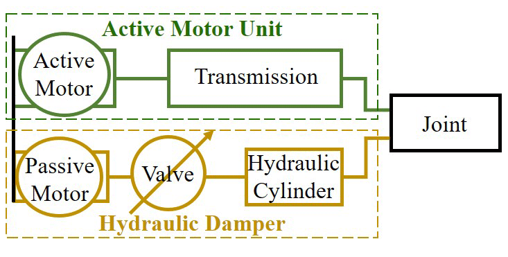
The proposed hybrid passive–active knee prosthesis, as shown in Fig. 1, consists of two main functional elements, namely (a) a hydraulic damper, which utilizes a hydraulic cylinder with an electrically controlled valve that adjusts the damping torque dynamically during each gait, and (b) an active motor unit, which consists of the active motor and the transmission system.
To determine when driving torque or damping torque is needed when walking on level ground, the normalized knee power PK was defined, as shown in Fig. 2, based on the gait data from Awad et al. (2016) and Pietraszewski et al. (2012). It is observed that most of the phases produce negative energy when walking on level ground, except for the initial stage of the swing extension phase and the stance extension phase between 15 % and 44 % of the cycle. During the stance extension phase, the knee joint is extended to increase the center of gravity to avoid the opposite toe touching the ground.

From the analysis of knee power during one gait cycle, it is determined that an active operating mode (II) is used in the stance extension phase between 15 % and 44 % of a cycle, and a passive operating mode (I) is used in the rest phases. The positive energy required during the initial stage of the swing extension phase is expected to be provided by the energy stored by the spring in the swing flexion phase rather than by the active driving unit, thus reducing the number of switches between active and passive modes and reducing energy consumption.
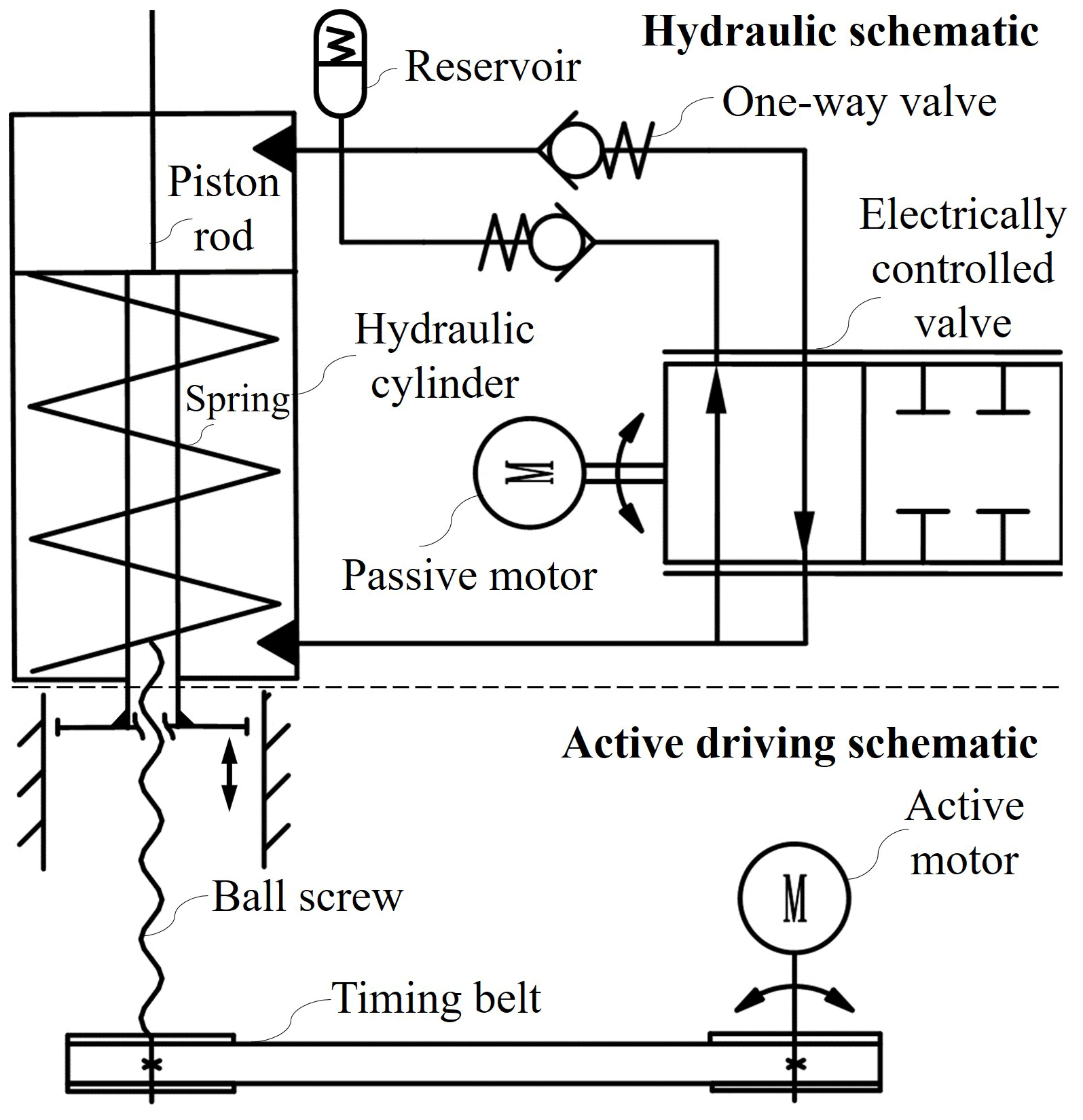
Based on idea above, the complete schematic diagram of the hybrid actuation system is proposed, as shown in Fig. 3. During passive operating modes, only the hydraulic damper is used to provide damping torque. A spring is arranged in the hydraulic cylinder. When the knee flexes, the piston rod moves downward, and the spring compresses and stores energy. When the knee extends, the spring releases energy. The upper and lower ends of the hydraulic cylinder, respectively, lead out two hydraulic oil channels with one-way valves in different directions, forming a flexion hydraulic oil circuit and an extension hydraulic oil circuit. An electrically controlled valve can simultaneously adjust the hydraulic oil flow in both circuits so as to adjust the flexion and extension damping torque dynamically. During active operating modes, the hydraulic damper is adjusted to the minimum damping, and the active motor unit works to provide driving torque. The transmission system of the active motor unit includes a timing belt and a ball screw, and the nut of the ball screw is connected with the bottom of the piston rod. When the active motor rotates, the ball screw can convert the rotary motion into linear motion, thus driving the piston rod movement.
2.2 Mechatronic structure design
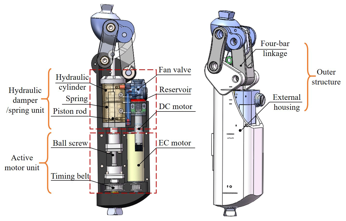
Figure 4 shows the 3D CAD model of the HPAK, which consists of three main components, namely (1) the outer structure, connected to the thigh and the bottom of the prosthesis, including the external housing and four-bar linkage, (2) the hydraulic damper–spring unit and (3) the active motor unit. Figure 5 shows the internal mechanical schematic for the HPAK.
The active motor unit includes an electronically commutated (EC) motor, a ball screw and timing belt arrangements. The EC motor (Maxon Motor AG; EC-4pole 30; 32 V, 150 W) drives the ball screw (THK ball screw; pitch diameter 6 mm; lead PB=1 mm; static–dynamic load ratings 0.54–0.94 kN; efficiency 89 %) with a timing belt transmission (teeth ratio – ). The timing belt is chosen to adapt to the axis distance between the motor and the screw when the motor rotates at high speed. The nut of the ball screw is linked to the piston rod so that the driving torque generated by the motor can be transmitted to the knee joint.
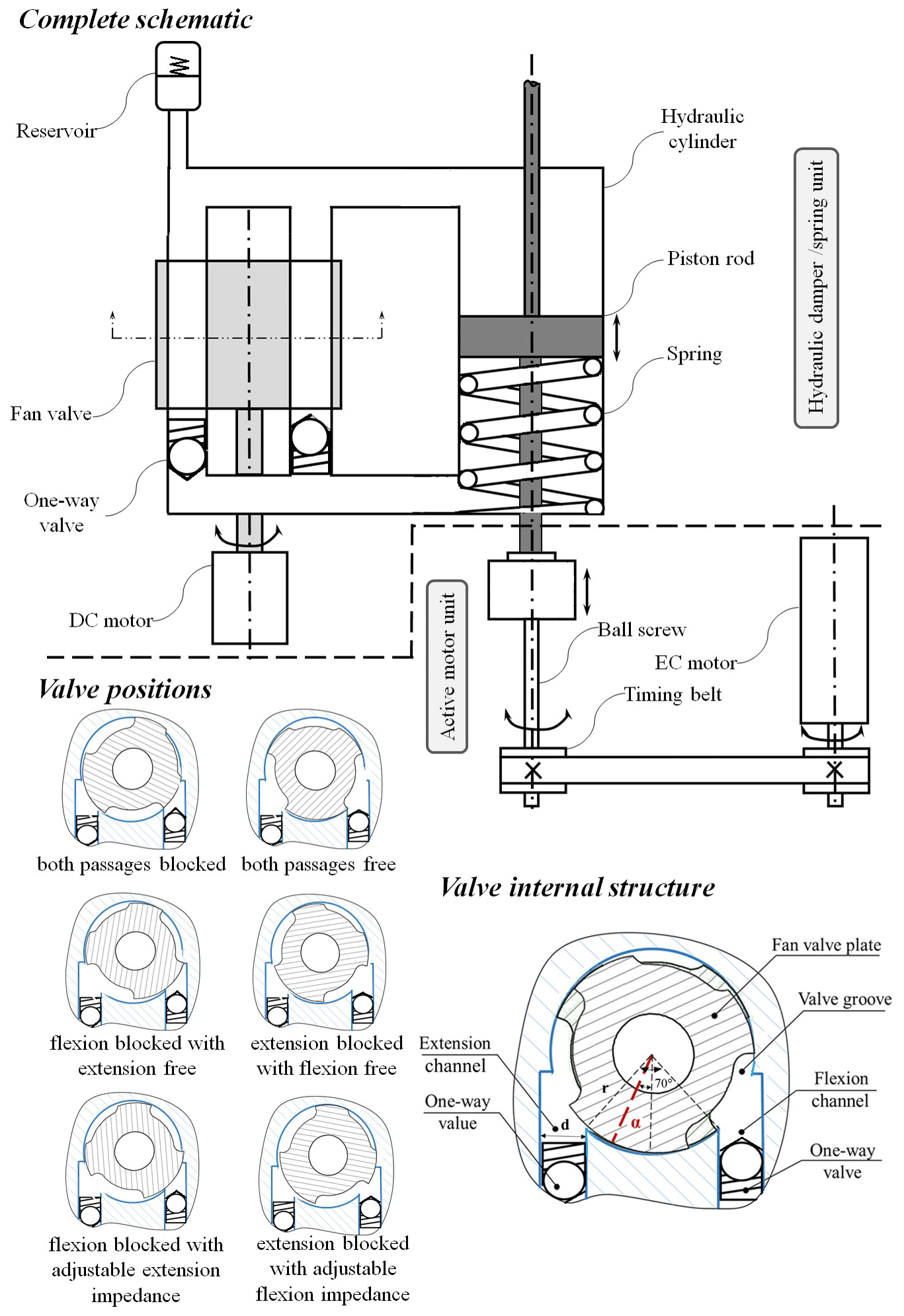
The hydraulic damper–spring unit employs a hydraulic cylinder with a novel fan valve controlled by a single direct current (DC) motor (Maxon Motor AG; DCX 10 L; 4.5 V, 1.5 W; gear stage 16:1) that dynamically adjusts both flexion and extension resistances throughout each gait cycle. As shown in Fig. 5, the two oil channels mentioned above coincide with the two valve grooves of the fan valve and two notches on the valve, respectively. The fan valve rotates continuously to adjust the overlapping area between the valve grooves and the hydraulic oil channels. Varying the valve angle between the primary positions adjusts the impedance to flow. Thus, the valve can adjust the required damping for stance flexion (mode I-1), preswing (mode I-2), swing flexion (mode I-3) and swing extension (mode I-4) at different speeds and for different activities. To convert the flexion and extension resistance to torque, the hydraulic damper is connected to the four-bar linkage through the piston rod.
The hydraulic damper is a spring–damper system. It generates a real-time varying damping torque during negative net energy tasks. The damping torque (τkd) of the hydraulic damper on the knee prosthesis can be obtained as follows:
where k is the elastic constant of the compression spring, Δx is the displacement of the piston rod, and L is the distance between the rotating center of the knee joint and the piston rod of the hydraulic cylinder, i.e., the length of the effective moment arm.
The resistance of the hydraulic cylinder can be represented as follows:
where A is an effective flow area of the cylinder, and ΔP is the pressure of the cylinder, which can be represented as follows:
where V is the speed of the piston rod, A0 is the flow area of the fan valve channel, Cd is the flow coefficient of the valve, and ρ is the density of hydraulic oil.
The change in hydraulic damping torque is achieved by adjusting the rotation angle of the fan valve, as shown in Fig. 4. The flow area of the fan valve channel can be determined by the following:
where α is the rotation angle of fan valve, r is the radius of fan valve, and d is the diameter of the extension and flexion channels.
From Eqs. (1) and (4), the hydraulic damping torque at the knee can be represented as follows:
In this paper, r=5 mm, d=2.50 mm, ρ=870 kg/m3, A = m2, Cd=0.7 and N/m.
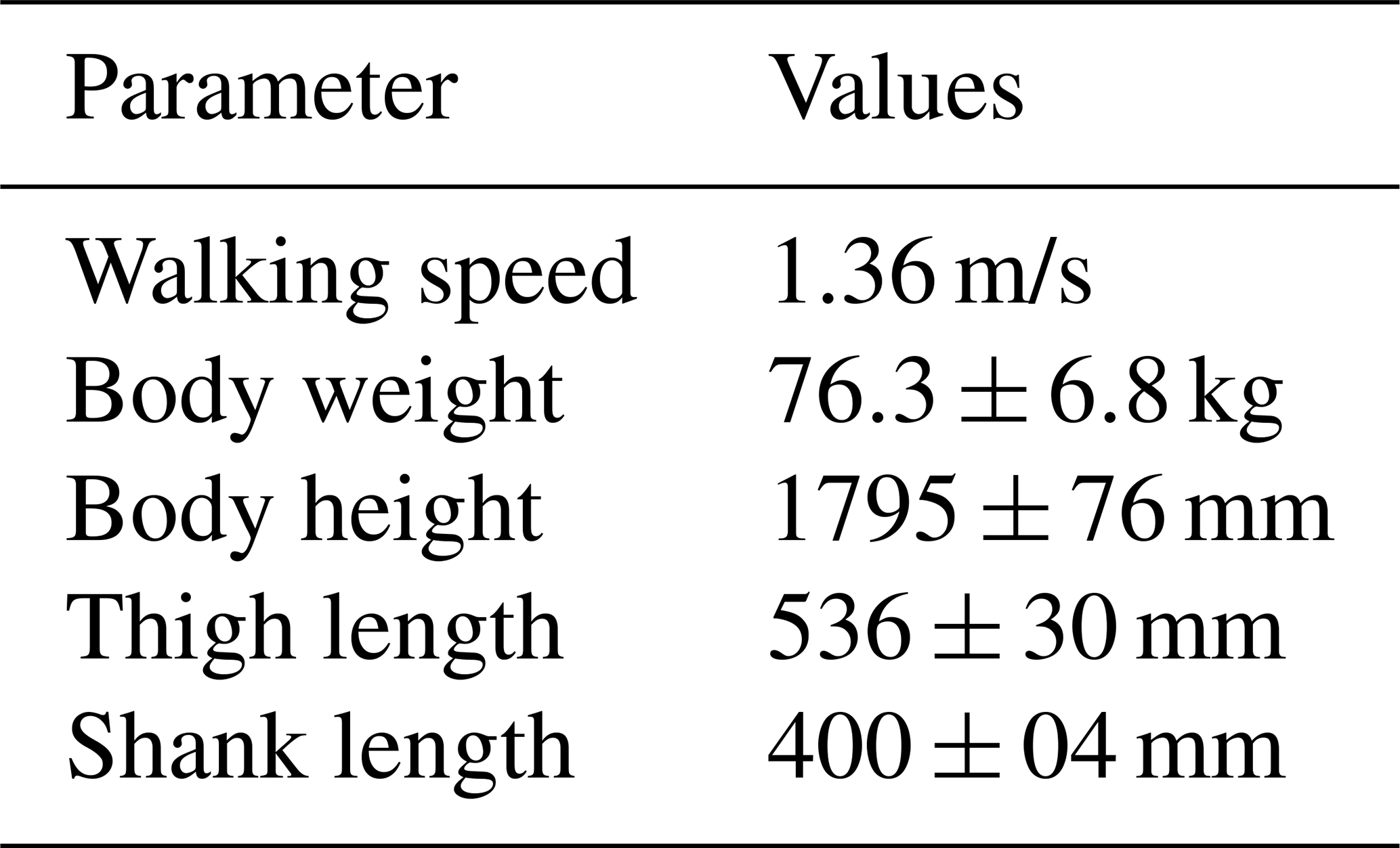
The energy consumption model mainly simulates the normalized knee torque and angle trajectory through the hybrid actuation system of the HPAK. It mainly calculates the power consumption of the active motor (EC-4pole 22) and passive motor (DCX 10 L) of the active motor unit and hydraulic damper, respectively, in a gait cycle and ignores the consumption due to controller electronics. The normalized knee torque (τk) and knee angle (θk) are based on the gait data of Awad et al. (2016) and Pietraszewski et al. (2012), as shown in Fig. 6. The anthropometric measurements and gait parameters are shown in Table 1.
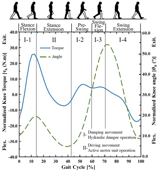
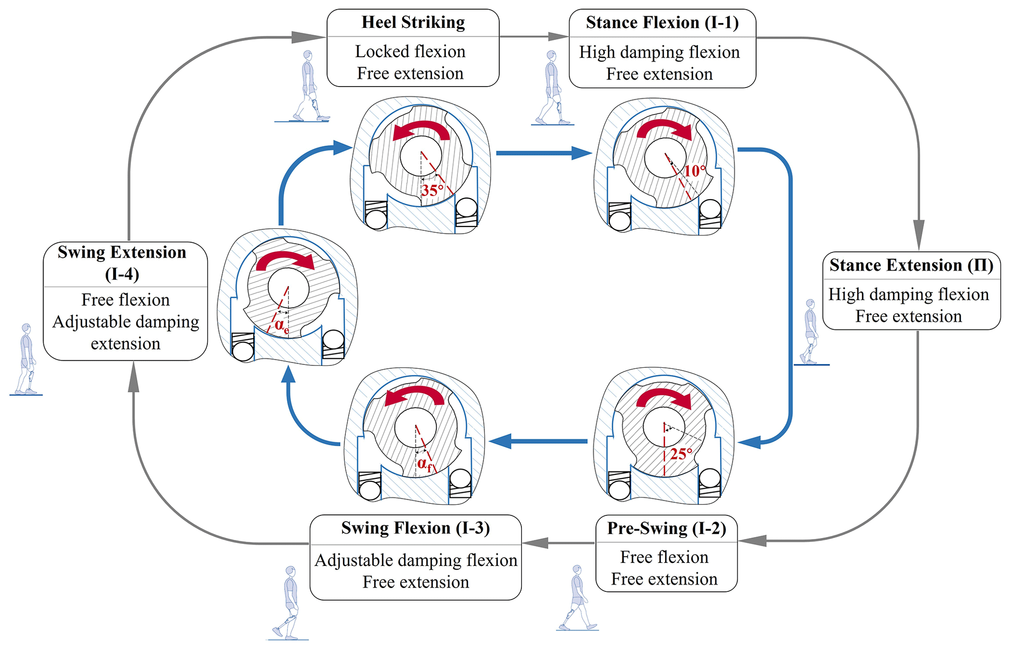
In contrast to the active motor as a direct torque source, the passive motor adjusts the oil flow impedance of the hydraulic damper by controlling the valve rotation angle, so the valve rotation angle trajectory in a gait cycle needs to be determined. The passive motor rotates according to the valve rotation angle for which the response time is close to 10 ms. Considering both energy consumption and physiological gait characteristics, the corresponding valve rotation angle in each operating mode is depicted in Fig. 7. When the heel strikes, the ground reaction force is strong, and the knee prosthesis plays a primary role in absorbing terminal shocks and supporting the body weight. The knee prosthesis should possess high stiffness and damping, so the flexion channel is closed by the passive motor controlling the fan valve, causing it to rotate 35∘, at which time the knee flexion is locked and the extension is free. During stance flexion (mode I-1), the flexion damping is high, with the fan valve rotating at 10∘ to enable the knee joint to flex, while ensuring security, and the extension damping is free to prepare for the next gait phase. During the preswing (mode I-2), the fan valve is in position so that both the flexion and extension channels are fully open, leaving both damping free to enable swing flexion. During swing flexion (mode I-3) and swing extension (mode I-4), the passive motor controls the rotation of the fan valve to provide the same damping torque as the normalized knee torque, which can be expressed as follows:
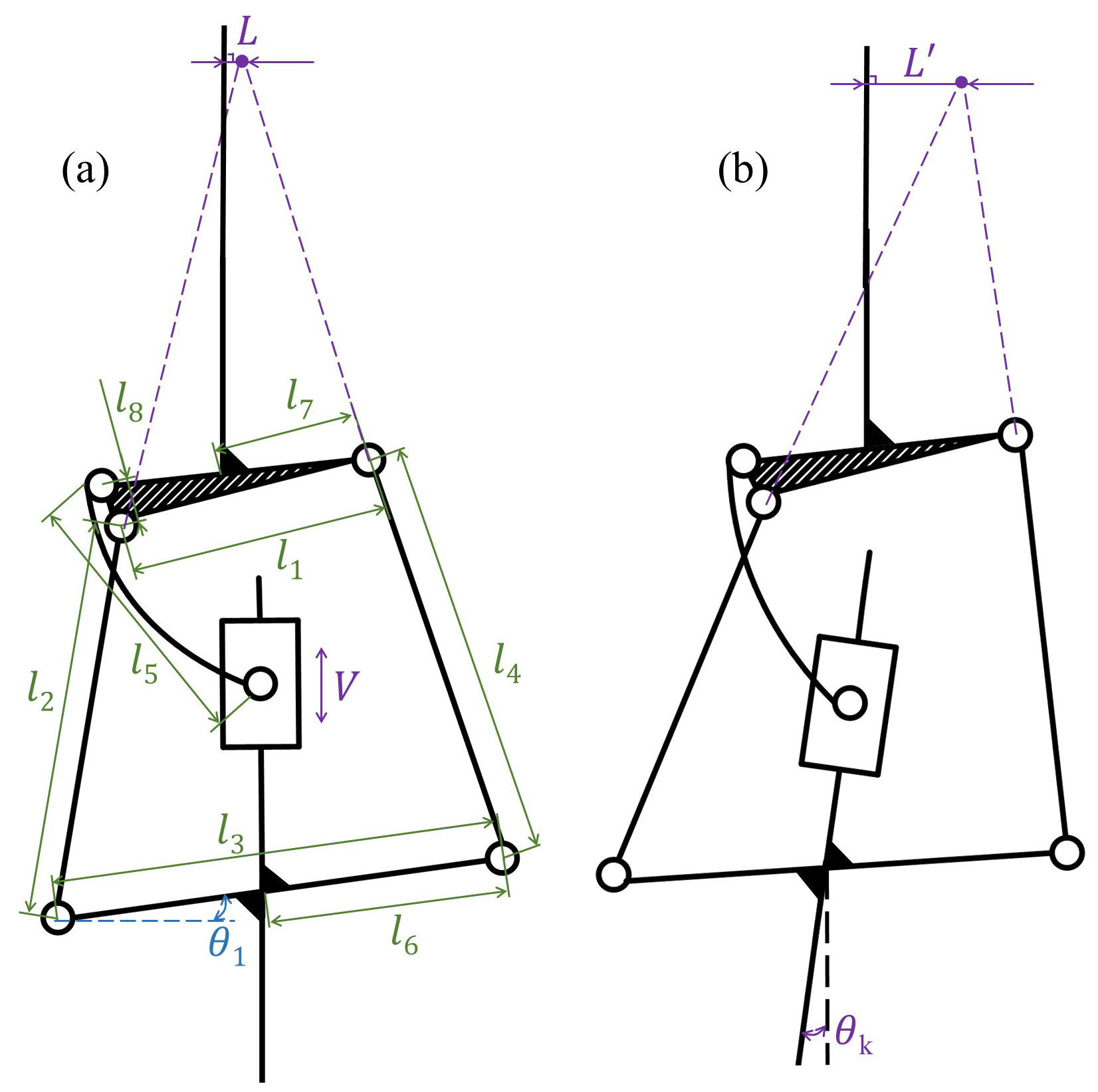
To solve Eq. (6), the speed of the piston rod (V) and the length of the effective moment arm (L) should be solved first. The HPAK adopts a four-bar linkage, and its equivalent diagram is shown in Fig. 8. Figure 8a shows the full extension of the prosthesis, and Fig. 8b shows the prosthesis flexion with θk. Since both the driving torque and the damping torque are applied first to the piston rod and are then transmitted to the knee joint, the hybrid actuator can be simplified as a prismatic pair in kinematic analysis. The dimensions of the bars are determined as l1=22 mm, l2=44 mm, l3=35 mm, l4=50 mm, l5=38 mm, l6=13 mm, l7=8 mm, l8=3 mm and . As shown in Fig. 8, the length of the effective moment arm L and L′ is the distance between the rotating center of the knee joint and the piston rod of the hydraulic cylinder. The equivalent model was established in Adams (MSC Software), and the normalized knee angle (θk) shown in Fig. 6 was used as the driver for the kinematics simulation, thus obtaining V and L of the whole gait cycle shown in Figs. 9 and 10. The known values of V, L and τk were substituted into Eqs. (5) and (6), and the rotation angle of the fan valve during the swing flexion (αf) and during swing extension (αe) were calculated in MATLAB, as shown in Fig. 11.
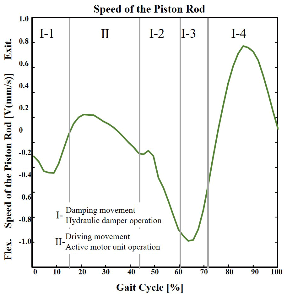
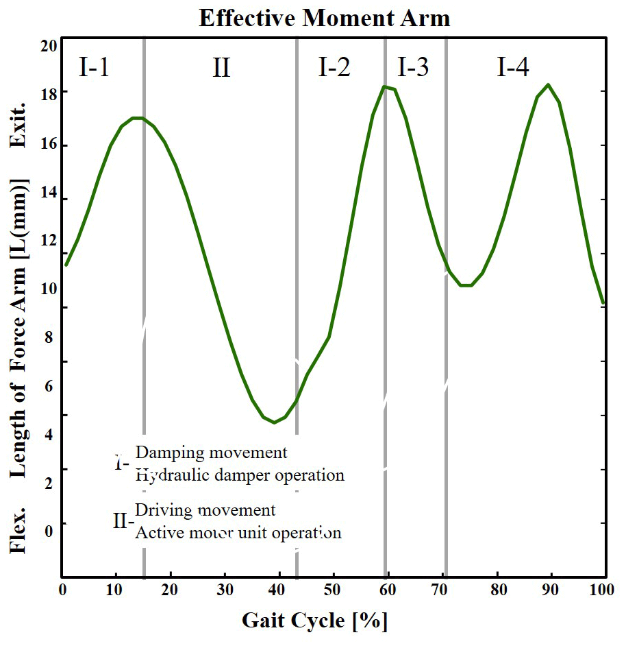
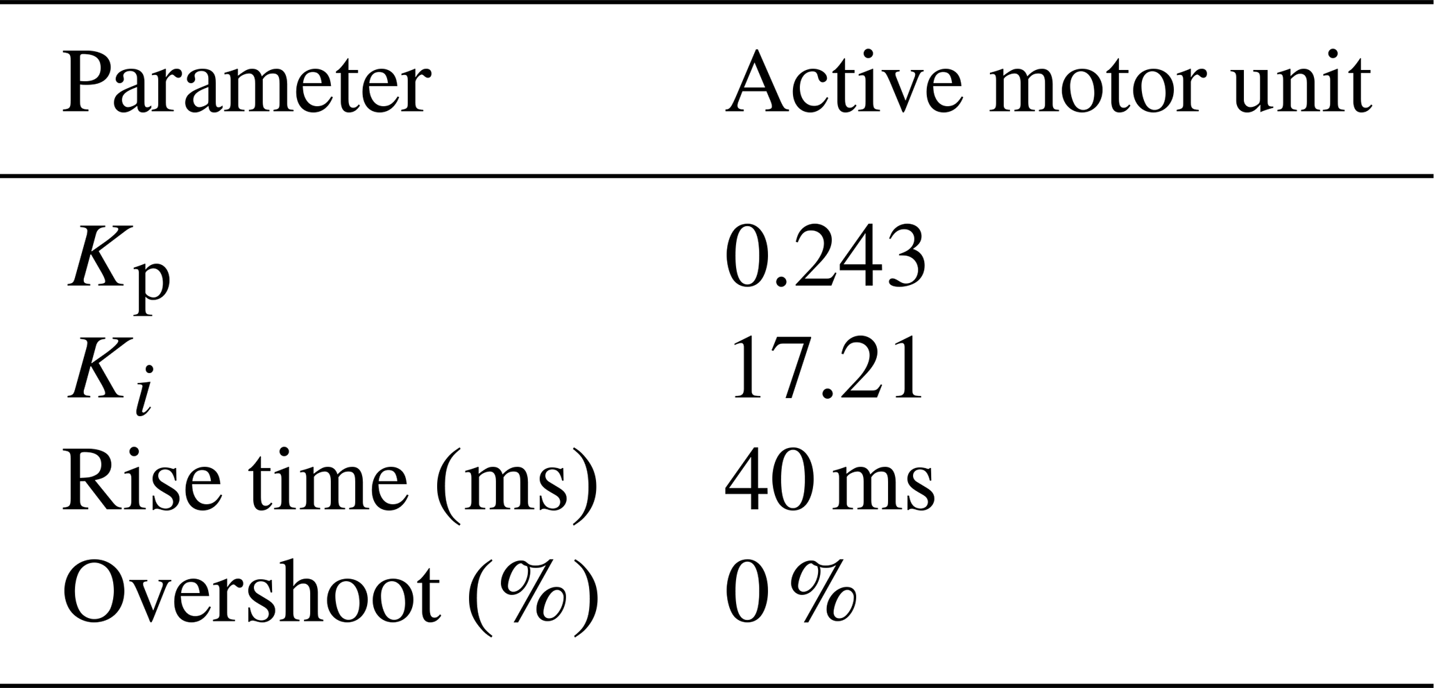
Figure 12 shows the block diagram of the energy consumption model used in the simulation. The normalized knee torque (τk), the speed of the piston rod (V), the length of the force arm (L) and the valve rotation angle (α) obtained by simulation were stored in the MATLAB workspace and were called inputs to the model in Simulink. The output torque of the active motor as a driving torque source was in proportion to the input current. The open loop torque response of the active motor input current was obtained by bench tests, as in Eq. (7). A proportional-integral (PI) controller was adjusted to make the subsystem respond quickly and stably, and its parameters are listed in Table 2.
For the HPAK, the conversion between the active motor unit (yellow) and the hydraulic damper (green) was realized by using a finite state controller. The conversion basis was the gait cycle period. The active motor unit operated just from 15 % to 44 % of the cycle. In the other gait phases, damping torque was needed, which was developed by the hydraulic damper. For the AKP, only the active motor unit model operated throughout the whole gait cycle. For the PKP, only the hydraulic damper model operated during the entire gait cycle.
The power consumption of the system was estimated based on the electric power consumption, as shown in the orange block in Fig. 12. In this analysis, consumption due to controller electronics was ignored. Full DC motor models were used to determine the electric power consumed by the active motor and the passive motor, as shown in the following:
where Pa and Pd are the motor power, Ia and Id are the armature current, Ua and Ud are the armature voltage, La and Ld are the armature inductance ( and ), Ra and Rd are the armature resistance (Ra=0.34 Ω and Rd=2.90 Ω), ωa and ωd are motor speed, kba and kbd are the motor electrical constant (kba=1.35 E-2 V s/rad and kbd=3.52 E-3V s/rad), and kvd is the motor speed constant (kvd=283.74 rad/s V). The motor's efficiency is 89 % and 75 %, respectively, and the reducer efficiency is a function of speed, according to the catalogs.
The energy consumption evaluation of the HPAK throughout a cycle can be obtained from the electric power consumption, as shown in the blue block in Fig. 12, which can be presented as follows:
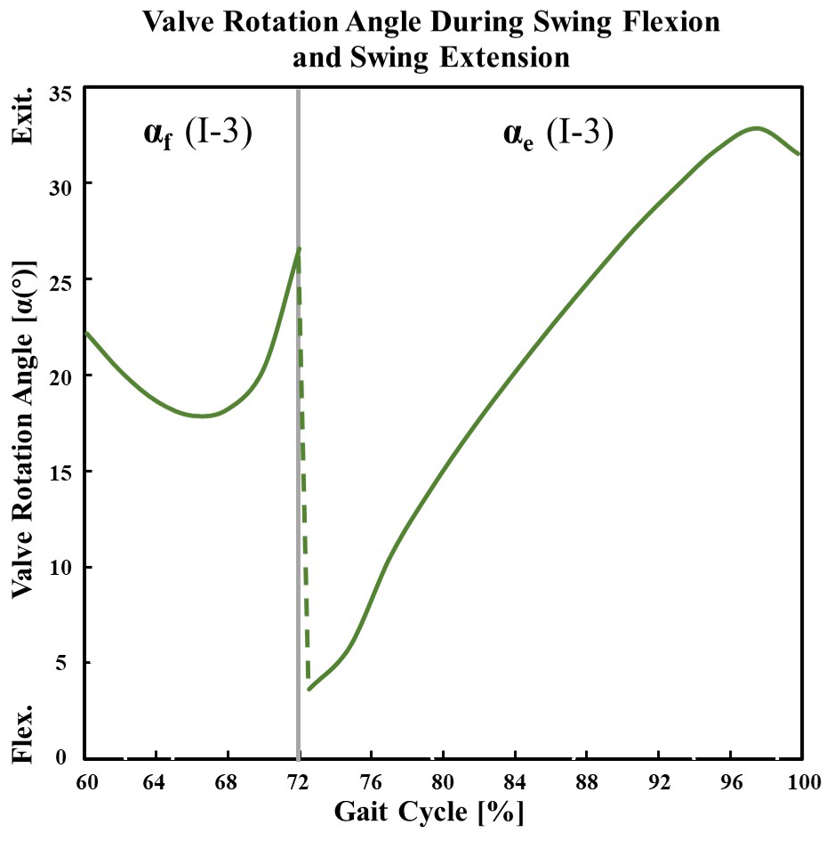
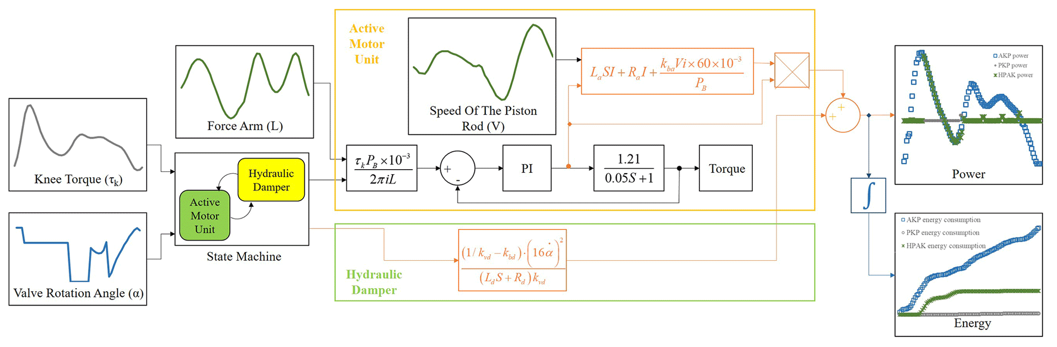
Figure 13 shows the comparison between the normalized torque and the torques applied at the knee joint by the active motor unit in the whole phase of the AKP and in the stance extension phase of the HPAK. The torque curve of the active drive motor is also shown in Fig. 13. It can be seen from the figure that the active motor unit can provide torques highly similar to the normalized knee torque. In the stance extension phase, the maximum torque need required by the active motor is 105.4 mN m, while the maximum continuous torque provided by the active motor is 106 mN m, according to the catalogs, so it can meet the requirements of the human body.
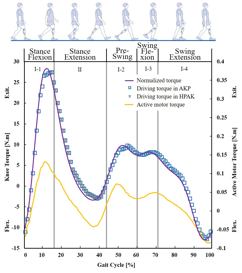
Figure 14 shows the power consumed by the HPAK (green points), the AKP (blue squares) and the PKP (gray circles) during a gait cycle.
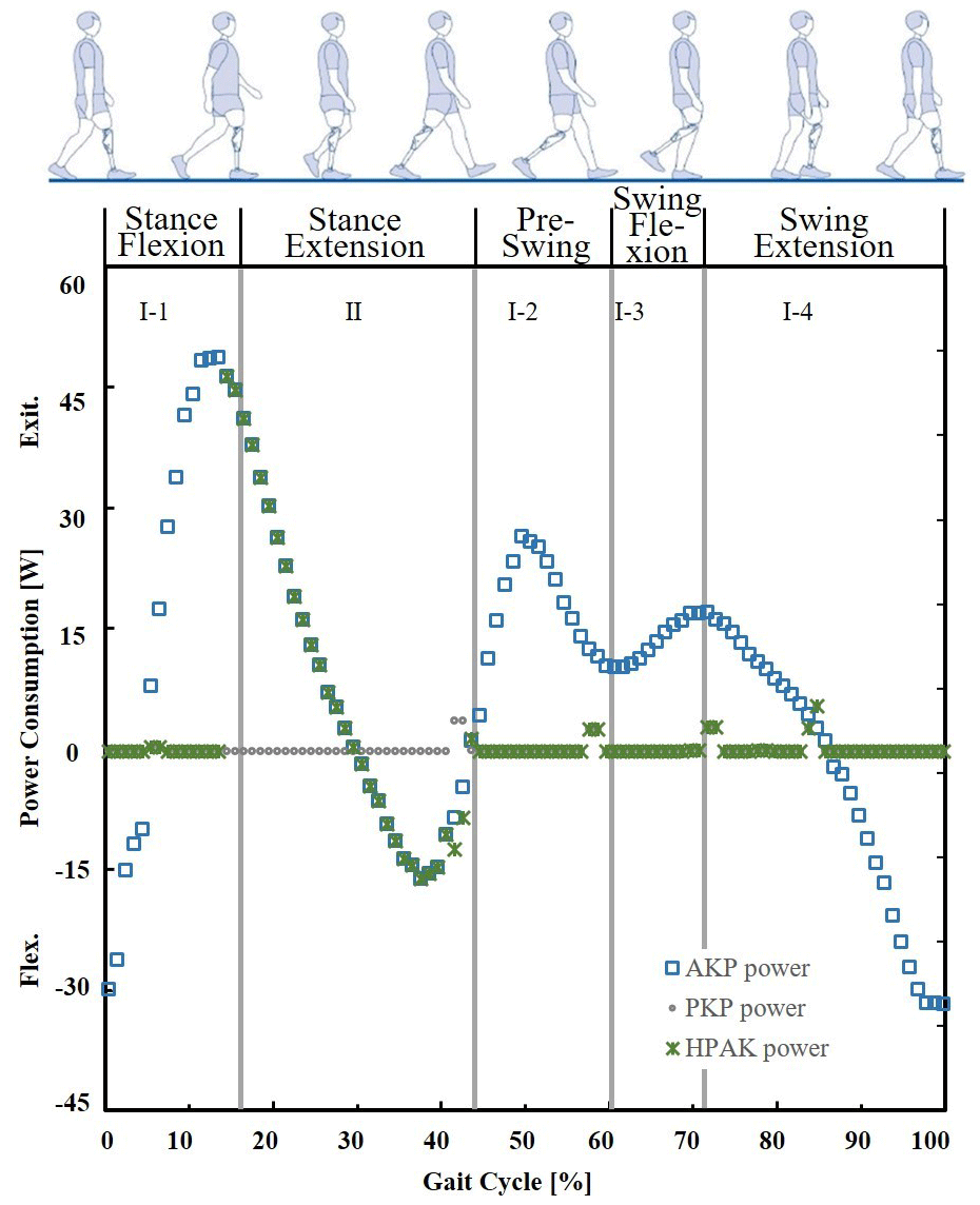
Figure 14The power consumed by the HPAK (green points), the AKP (blue squares) and the PKP (gray circles) during a gait cycle.
The AKP consumes more power at four different times. First, when the heel strikes the ground at the start of the cycle, the prosthesis plays a primary role in absorbing terminal shocks and supporting the body weight due to the strong ground-reacting force. Second, during the stance extension phase, between 15 % and 44 % of the cycle, the knee joint is extended to increase the center of gravity and to avoid the opposite toe touching the ground. Third, during the preswing phase, between 44 % and 60 % of the cycle, when the healthy leg enters the stance phase, the hip continually extends and the knee extensors contract eccentrically to project the body weight onto the knee. Fourth, from 85 % to 95 % of the end of the cycle, the eccentric contraction of the flexors slows down the extension of the knee joint to reach the initial heel striking position. In the second moment, power must be provided to increase the center of gravity, while, in the other three periods, energy must be dissipated to decrease the joint acceleration.
The PKP consumes the least power of the three simulation conditions. In the stance phase, only a small amount of power consumption is generated at the moment of the heel striking and entering the two phases of stance flexion and preswing. In the stance phase, despite the passive motor working continuously, the power consumed in this cycle interval is not high due to the small range of the motor rotation angle and the low rotation speed of the motor. The huge difference in power consumption between the AKP and the PKP also proves that it is energetically unfavorable to use electric motors as a damper, as expected.
The HPAK uses the active motor unit only when driving torque is required between 15 % and 44 % of the cycle. When power needs to be dissipated, only the hydraulic damper operates. This strategy results in much lower power levels than the AKP, especially in the swing phase when consumption is higher.
Figure 15 presents a comparison of the energy consumption under the three simulation conditions. The energy consumption of the PKP is only 1.24 J, which is lower than that of most other passive prostheses. For example, Mousavi and Sayyaadi (2018) proposed a magnetorheological (MR) damper via a T-shaped drum with an arc-form surface boundary for passive knee orthosis. The prototype consumed 5.8 W when walking on level ground, considering 1.7 s per cycle, and the average energy consumption was 9.86 J per cycle. A knee prosthesis with an MR damper, manufactured by the Össur company, was also used for comparison in the research of Mousavi and Sayyaadi (2018), and its average energy consumption was 10.03 J per cycle. Martinez-Villalpando et al. (2008) from MIT proposed an agonist–antagonist active knee prosthesis. When walking on level ground, however, this design permitted the use of a passive control scheme, while the active elements were used primarily to independently control the engagement of each tendon-like spring, thereby controlling the transformation of potential energy into kinetic energy, so it could be considered as a variable-stiffness passive prosthesis in level ground walking. Simulation results predicted a minimal energy consumption of 5.66 J per cycle, assuming an average gait cycle duration of 1.22 s per cycle. To sum up, the PKP proposed in this paper can effectively reduce energy consumption, which mainly benefits from the spring–hydraulic damper structure design with novel fan valve and the effective damping control strategy.
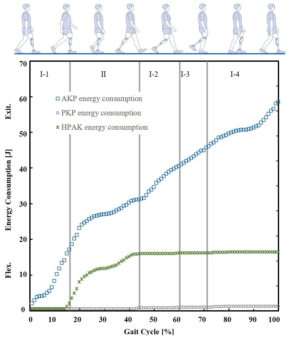
Figure 15Energy consumption under the three simulation conditions when walking on level ground.
The AKP consumes a total of 58.95 J of energy during the cycle (Fig. 15; blue squares). The AKP in this paper represents a class of active knee prostheses with a single actuator transmission system directly coupled to the knee joint. Similar to the AKP, Sup et al. (2009) designed an active knee prosthesis with an actuator based on a 200 W brushless motor powering the knee joint through a ball screw and consuming 91.08 J per cycle. The energy consumption of this kind of direct drive actuation is generally high, as the motor will consume electrical power during those phases when it is not producing mechanical output energy. To solve this problem, hybrid passive–active actuation is a good solution, as it can be divided into two strategies, namely (1) coupling the independent damper and the power source and (2) combining the power source and elastic elements to realize the elastic driving, so as to store and release energy in the gait phases. The HPAK in this paper belongs to the former strategy.
The HPAK consumed only 16.19 J (green circles; Fig. 15), which is 3.6 times lower than the AKP. It is worth noting that the greatest energy consumed by the HPAK occurs during the stance flexion phase, especially between 10 % and 21 % when the knee prosthesis needs to support the body weight and ensure safety, during the preswing phase, especially between 48 % and 60 % when the hip extension results in increased pressure being projected on the knee, and during the swing phase, between 90 % and 100 % of the cycle (terminal swing) when the angular velocity is high. Along with the HPAK, there are other knee prostheses using the former strategy, such as the prosthesis proposed by Park et al. (2016), which was equipped with the MR damper and EC motor, and the semiactive knee proposed by Lambrecht et al. (2009), which combined a passively damped hydraulic device with a fully active device. In the knee prostheses with hybrid passive–active actuations using the latter strategy, the MIT clutchable series elastic actuator (CSEA; Rouse et al., 2014) is the typical one. Based on their previous research, the team from MIT presented the CSEA which comprised a clutchable series elastic actuator with a DC motor and a low-power (6 W) electromagnetic clutch that was used to store the energy in the springs more efficiently by locking the motor. The control strategy was also improved by adopting the hybrid passive–active driving strategy that supplied positive power in the early swing flexion phase and the early swing extension phase and nonlinear damping in other phases. Benefiting from the clutch mechanism, the net electrical energy consumption was only 3.6 J per cycle, but it also brought the drawbacks of limited maximum impedance and no additional torque provided by the motor when the clutch is activated, which can be avoided by the HPAK proposed in this paper. The above results suggest that it is a good method to use a driving torque supply (active motor unit) throughout the stance extension phase and an adjustable damping torque supply (hydraulic damper) to dissipate energy in order to reduce the energy consumption of a prosthesis without affecting the gait symmetry. Prototype production and subject tests to further verify the reliability of the mechanism will be conducted in future work.
This paper presented the design of a hybrid passive–active knee prosthesis (HPAK) that can provide driving and damping torque. The energy consumptions of the HPAK under three different simulation conditions were also evaluated by computer simulation, namely (a) the complete HPAK operating, (b) only the active motor unit operating and simulating an active knee prosthesis (AKP) and (c) only the hydraulic damper operating and simulating a passive knee prosthesis (PKP). The results showed that HPAK, which used the active motor unit only throughout the stance extension phase when the body's center of gravity is required to increase, consumed 3.6 times lower energy than the AKP, which used the active motor unit in the entire gait cycle, just like some other active prostheses in the market. In addition, the PKP consumed very low energy, which is attributed to the spring–hydraulic damper structure designed in this paper, which can only realize one motor adjusting two channels. These results suggest that, (a) in order to reduce the energy consumption and maintain the gait symmetry of an active prostheses, it can play an important role in utilizing the active power supply only when driving torque is required, and the energy dissipation needs to be completed by low power consumption and adjustable dampers; in addition, (b) the proposed novel hybrid passive–active knee prosthesis can perform well to reduce the energy consumption and improve the approximation of healthy knee behavior when walking on level ground, compared to active or passive knee prostheses.
All data included in this study are available upon request from the corresponding author.
XW proposed and developed the overall concept of the paper, conducted the mechanism design and simulations and wrote the majority of the paper. QM and HY supervised and structured the paper. ZZ helped to make the figures. JS edited the paper, and JY helped write the paper.
The authors declare that they have no conflict of interest.
The authors would like to thank the support of National Key Research and Development Program of China (grant no. 2018YFB1307303) and National Natural Science Foundation of China (grant no. 62073224).
This research has been supported by the National Key Research and Development Program of China (grant no. 2018YFB1307303) and the National Natural Science Foundation of China (grant no. 62073224).
This paper was edited by Guowu Wei and reviewed by Qitao Huang and one anonymous referee.
Ahn, H. J., Lee, K. H., and Lee, C. H.: Design optimization of a knee joint for an active transfemoral prosthesis for weight reduction, J. Mech. Sci. Technol., 31, 5905–5913, https://doi.org/10.1007/s12206-017-1134-9, 2017.
Andrade, R. M., Filho, B., Vimieiro, C. B. S., and Pinotti, M.: Evaluating Energy Consumption of an Active Magnetorheological Knee Prosthesis, in: 19th International Conference on Advanced Robotics (ICAR), Belo Horizonte, Brazil, 2–6 December 2019, 75–80, 2019.
Awad, M. I., Dehghani-Sanij, A. A., Moser, D., and Zahedi, S.: Motor electrical damping for back-drivable prosthetic knee, in: 11th France-Japan & 9th Europe-Asia Congress on Mechatronics (MECATRONICS)/17th International Conference on Research and Education in Mechatronics (REM), Compiegne, France, 15–17 June 2016, 348–353, 2016.
Cao, W., Yu, H., Zhao, W., Meng, Q. L., and Chen, W. M.: The comparison of transfemoral amputees using mechanical and microprocessor-controlled prosthetic knee under different walking speeds: A randomized cross-over trial, Technol. Health Care, 26, 1–12, https://doi.org/10.3233/THC-171157, 2018a.
Cao, W., Yu, H., Zhao, W., Meng, Q. L., and Chen, W. M.: Structure Design and Motion Simulation of a Microprocessor-Controlled Prosthetic Knee, in: International Conference on Man-Machine-Environment System Engineering, Singapore, December 2018, 107–114, 2018b.
Cappozzo, A., Figura, F., Gazzani, F., Leo, T., and Marchetti, M.: Angular displacements in the upper body of AK amputees during level walking, Prosthet. Orthot. Int., 6, 131, https://doi.org/10.3109/03093648209166573, 1982.
Geeroms, J., Flynn, L., Jimenez-Fabian, R., Vanderborght, B., and Lefeber, D.: Design and energetic evaluation of a prosthetic knee joint actuator with a lockable parallel spring, Bioinspir. Biomim., 12, 026002, https://doi.org/10.1088/1748-3190/aa575c, 2017.
Goldfarb, M., Lawson, B. E., and Shultz, A. H.: Realizing the promise of robotic leg prostheses, Sci. Trans. Medic., 5, 210ps15, https://doi.org/10.1126/scitranslmed.3007312, 2013.
Highsmith, M. J., Goff, L. M., and Lewandowski, A. L.: Low back pain in persons with lower extremity amputation: a systematic review of the literature, The Spine Journal, 19, 552–563, https://doi.org/10.1016/j.spinee.2018.08.011, 2019.
Lambrecht, B. G. A. and Kazerooni, H.: Design of a semi-active knee prosthesis, in: 2009 IEEE International Conference on Robotics and Automation, Kobe, Japan, 12–17 May 2009, 639–645, 2009.
Martinez-Villalpando, E. C., Weber, J., Elliott, G., and Herr, H.: Design of an agonist-antagonist active knee prosthesis, in: 2nd IEEE Ras & Embs International Conference on Biomedical Robotics and Biomechatronics, Scottsdale, AZ, USA, 19–22 October 2008, 529–534, 2008.
Mousavi, S. H. and Sayyaadi, H.: Optimization and testing of a new prototyped hybrid MR brake with arc form surface as a prosthetic knee, IEEE-ASME T. Mech., 23, 1204–1214, https://doi.org/10.1109/TMECH.2018.2820065, 2018.
Park, J., Yoon, G. H., Kang, J. W., and Choi, S. B.: Design and control of a prosthetic leg for above-knee amputees operated in semi-active and active modes, Smart Mater. Struct., 25, 085009, https://doi.org/10.1088/0964-1726/25/8/085009, 2016.
Pieringer, D. S., Grimmer, M., Russold, M. F., and Riener, R.: Review of the actuators of active knee prostheses and their target design outputs for activities of daily living, in: International Conference on Rehabilitation Robotics (ICORR), London, England, 17–20 July 2017, 1246–1253, 2017.
Pietraszewski, B., Winiarski, S., and Jaroszczuk, S.: Three-dimensional human gait pattern–reference data for normal men, Acta Bioeng. Biomech., 14, 9–16, https://doi.org/10.1155/2019/9232430, 2012.
Price, M. A., Beckerle, P., and Sup, F. C.: Design Optimization in Lower Limb Prostheses: A Review, IEEE T. Neur. Sys. Reh., 27, 1574–1588, https://doi.org/10.1109/tnsre.2019.2927094, 2019.
Rouse, E. J., Mooney, L. M., and Herr, H. M.: Clutchable series-elastic actuator: Implications for prosthetic knee design, Int. J. Robot. Res., 33, 1611–1625, https://doi.org/10.1177/0278364914545673, 2014.
Rupar, M., Vucina, A., Dedic, R., Dedic, R., and Dindo, H.: Overview of the development of hydraulic above knee prosthesis, in: CMBEBIH, Sarajevo, 16–18 March 2017, 218–222, 2017.
Seid, S., Chandramohan, S., and Sujatha, S.: Optimal design of an MR damper valve for prosthetic knee application, J. Mech. Sci. Technol., 32, 2959–2965, https://doi.org/10.1007/s12206-018-0552-7, 2018.
Sup, F., Varol, H. A., Mitchell, J., Withrow, T. J., and Goldfarb, M.: Preliminary evaluations of a self-contained anthropomorphic transfemoral prosthesis, IEEE-ASME T. Mech., 14, 667–676, https://doi.org/10.1109/tmech.2009.2032688, 2009.
Torrealba, R. R. and Fonseca-Rojas, E. D.: Toward the Development of Knee Prostheses: Review of Current Active Devices, Appl. Mech. Rev., 71, 030801, https://doi.org/10.1115/1.4043323, 2019.
Tran, M., Gabert, L., Cempini, M., and Tommaso, L.: A Lightweight, Efficient Fully-Powered Knee Prosthesis with Actively Variable Transmission, IEEE Robotics and Automation Letters, 4, 1186–1193, https://doi.org/10.1109/LRA.2019.2892204, 2019.
Persons' Federation, China Disabled: The total number of population with disabilities in China by the end of 2010, available at: http://www.cdpf.org.cn/sjzx/cjrgk/201206/t20120626_387581.shtml, last access: 26 June 2012.