the Creative Commons Attribution 4.0 License.
the Creative Commons Attribution 4.0 License.
 | 27 Oct 2020
Singularity and branch identification of a 2 degree-of-freedom (DOF) seven-bar spherical parallel manipulator
Liangyi Nie
Huafeng Ding
Andrés Kecskeméthy
Jinqiang Gan
Jun Wang
Kwun-lon Ting
Spherical parallel manipulators (SPMs) have a great potential for industrial applications of robot wrists, camera-orientating devices, and even sensors because of their special structure. However, increasing with the number of links, the kinematics analysis of the complex SPMs is formidable. The main contribution of this paper is to present a kind of 2 degree-of-freedom (DOF) seven-bar SPM containing two five-bar spherical loops, which has the advantages of high reaction speed, accuracy rating, and rigidity. And based on the unusual actuated choices and symmetrical loop structure, an approach is provided to identify singularities and branches of this kind of 2 DOF seven-bar SPM according to three following steps. Firstly, loop equations of the two five-bar spherical loops, which include all the kinematic characteristics of this SPM, are established with joint rotation and side rotation. Secondly, branch graphs are obtained by Maple based on the discriminants of loop equations and the concept of joint rotation space (JRS). Then, singularities are directly determined by the singular boundaries of the branch graphs, and branches are easily identified by the overlapping areas of JRS of two five-bar spherical loops. Finally, this paper distinguishes two types of branches of this SPM according to whether branch points exist to decouple the kinematics, which can be used for different performance applications. The proposed method is visual and offers geometric insights into understanding the formation of mobility using branch graphs. At the end of this paper, two examples are employed to illustrate the proposed method.
- Article
(4461 KB) - Full-text XML
- BibTeX
- EndNote


Mobility identification is a basic problem in linkage analysis and synthesis, which includes branch analysis, sub-branch analysis, the full rotatability problem, and order of motion (Ting, 1989, 1993; Liu and Ting, 1991, 1992). Singularities are the core of the full rotatability problem, which represent the singular configurations of the manipulator. At these configurations, the manipulator may lose control momentarily and has zero mechanical advantage (Gosselin and Angeles, 1990; Yan and Wu, 1989; Hunt, 1978). Since singularities are commonly harmful and even damage the manipulator, it is necessary to identify all singularities of the spherical parallel manipulator (SPM) during the design stage.
Branches (or circuits) (Chase and Mirth, 1993; Davis and Chase, 1994; Mirth, 1995; Ting and Dou, 1996; Ting, 1994) are the most fundamental problem among the various aspects of mobility issues. Generally speaking, branches should be identified and rectified first. A branch is a gather of manipulator configurations, referring to the continuity motion of the manipulator. And a manipulator configuration cannot transform from one branch to another without disconnecting the manipulator. Branches are determined by the links' size of the spherical loops and are irrelevant to the input conditions (Ting and Dou, 1996; Ting, 1994; Ting et al., 2008, 2010).
A spherical manipulator has a special structure whose rotation axes of all links intersect at the center of the sphere. In some senses, a planar manipulator can also be considered to be a special spherical manipulator whose common center point of the rotation joints is at infinity. In comparison with the majority of planar parallel manipulators, spherical parallel manipulators have the advantages of large workspace, large payload, large stiffness, low inertia, and high dynamic performance when they have the same number of links. Therefore, they have attracted a considerable amount of research. According to the Burmester problem, Ruth and McCarthy (1999) presented a computer-aided design software system that is suitable for spherical four-bar linkages. Bai et al. (2009) used four-bar spherical chains to establish the input–output (I/O) equations of spherical four-bar linkages for the forward displacement relationship of the spherical parallel robots. Sun et al. (2018) presented a wavelet feature parameter method for the non-periodic design requirements. By establishing a mathematical model for the coupler curve of the spherical four-bar linkage, the geometrical characteristics of the open path are described to calculate installation positions of the desired linkage. For spherical six-bar path generation linkage, Yang and Xu (2005) proposed a synthesis method to make the linkage into some link groups, and the constraint conditions and object functions are given. An approach was proposed by Sancisi, Parenticastelli, and Baldisserri (2017) to analyze the human ankle joint with the spherical model. Di Gregorio (2018) developed an analytical method for the singularity analysis and exhaustive enumeration of the singularity conditions in single degree-of-freedom (DOF) spherical mechanisms. Owing to the analytical method, the generated systems of equations are used to find the singularities of a given mechanism and to synthesize mechanisms which have specific requirements for the singularities. Using the construction characteristics of the spherical six-bar linkage, Hernandez et al. (2006) designed a new gearless robotic pitch-roll wrist which consists of spherical cam rollers and spherical Stephenson linkages. Driven by roller-carrying disks, the whole system works as a differential mechanism. Wampler (2004) employed rotation matrices or equations to locate the displacement analysis of spherical linkages up to three loops. The solution method is a modification of Sylvester's elimination method. Nie and Wang (2018) solved the branch problem of the spherical six-bar linkage based on the loop equations. Duan et al. (2018) proposed a new 2 DOF spherical parallel manipulator which can be applied for an orientation device, or a torque sensor, and they also carried out a typical motion plan, simulations, and actuating torque needed for these motions by employing derived inverse dynamic equations. Danaei and Arian (2018) analyzed the dynamic modeling and inertial parameter determination of a general 5R 2 DOF spherical parallel manipulator. According to the proposed eliminating and grouping operation, the computation time is reduced by 37 %. For the tasks on a mini-/microscale, Palpacelli et al. (2018) proposed a sensitivity analysis for an error model of a mini 2 DOF five-bar spherical parallel manipulator to geometrically calibrate its kinematics. Wu and Bai (2019) redesigned a 3-RRR spherical parallel manipulator of co-axis input with reconfigurability and investigated the workspace, dexterity, and singularity of the new manipulator. Elgolli et al. (2019) presented a method for the dynamic problem of a 3-RRR spherical parallel manipulator using the Kane method and D'Alembert's principle. The obtained model can also be used for sensitivity analysis and a dimensional optimization to ensure a constant dynamic transmission over the entire desired workspace. Based on the concept of an equivalent spherical mechanism, Boscariol et al. (2017) proposed a method to investigate the direct kinematic problem of a tunnel digging machine, which reduces a lot of computation time compared to the traditional numerical solution. Nelson et al. (2018) provided a redundant serial spherical linkage to avoid collision with the patient and to produce good kinematics and workspace. Bai et al. (2019) reviewed the state of the art of spherical-motion-generator kinematics, dynamics, design optimization, and novel spherical mechanisms with emerging applications and discussed some new research problems and future developments. As can be seen from the discussion above, the research mainly focuses on simple SPMs such as spherical four-bar linkage (Ruth and McCarthy, 1999; Sun et al., 2018), spherical six-bar linkage (Yang and Xu, 2005), and 2 DOF five-bar SPMs (Duan et al., 2018). But for complex SPMs, such as the 2 DOF seven-bar SPMs, although they have the advantages of more types of topologies and higher rigidity compared to 2 DOF five-bar SPMs, there still is limited literature available. The reason for this is that the loop equations of complex SPMs are difficult to solve. With the number of links increasing, too many unknown variables are brought into the loop equations and cannot be eliminated, contrasting with simple SPMs, resulting in no solutions. However, in this study, the unusual actuated choices and symmetric loop structure of this kind of SPM make the loop equations solvable. And the roots can be obtained using the discriminant method. In other words, the kinematics characteristics of these SPMs can be studied. This kind of 2 DOF seven-bar SPM may provide another potential choice for industry application such as cardans (Kong and Gosselin, 2004), robot wrists (Gosselin and Hamel, 1994), camera-orientating devices (Li and Payandeh, 2002), and even sensors (Duan et al., 2018). The proposed method may also become a powerful design aid when the manipulation has singularity and branch requirements (Sect. 5) during the design stage. It gives a clear graphical interpretation and is also valid for existing simple SPMs.
The motivation of this paper is to study 2 DOF seven-bar SPMs to attract more research about complex SPMs. In addition, the identification of singularities and branches of the 2 DOF seven-bar SPM also provides a theoretical basis for the industrial application of this kind of SPM. Based on loop equations, singular configurations are located with the discriminants of two five-bar spherical loop equations. Then, using joint rotation space (JRS; Ting, 2008), the branch graph, which includes all the kinematic information of the 2 DOF seven-bar SPM, is obtained to identify the branches.
The first contribution of this paper is to provide a kind of 2 DOF seven-bar SPM with two spherical five-bar loops, which gives another potential choice for industry application. Compared to 2 DOF five-bar SPMs, this kind of SPM has higher rigidity. The second one is first to succeed in identifying singularities and branches of the 2 DOF seven-bar SPM, utilizing the unusual actuated choices and symmetric loop structure. And the beauty of it is that the unusual actuated choices and symmetric loop structure not only enable complex loop equations to be solved but also bring many other advantages to the SPM. Owing to the unusual actuated choices, the SPM has the advantage of high reaction speed. Meanwhile, only containing two five-bar spherical loops, this kind of 2 DOF seven-bar SPM, a symmetric loop manipulator, has several merits, such as easy control, compared to other planar linkages or SPMs. The third one is to use a branch graph to explain the kinetic characteristics of the SPM, which provides geometric insights into understanding the mobility information instead of a complex formula set. Branch graphs are not the workspace but the input joint rotation ranges which can be effectively utilized when the SPMs are required for a specific input range or branch choice (discussed in Sect. 5). The fourth one is to distinguish the branches of 2 DOF seven-bar SPMs as two types according to whether branch points exist in the corresponding branch graph, which offers convenience when the manipulator faces decoupling motion demand (discussed in Sect. 6).
This paper is organized as follows. In Sect. 2, the 2 DOF seven-bar SPM is presented, and the input condition is decided. In Sect. 3, the loop equations of the two five-bar spherical loops are established based on the concepts of joint rotation and side rotation. Then, the singularities are obtained by saving the discriminants of the two five-bar spherical loop equations in Sect. 4. Subsequently, two types of branches of the 2 DOF seven-bar SPM are identified according to joint rotation space and branch points in Sect. 5. Finally, two examples are illustrated for the validity of the proposed method. And conclusions are presented at the end of this paper.
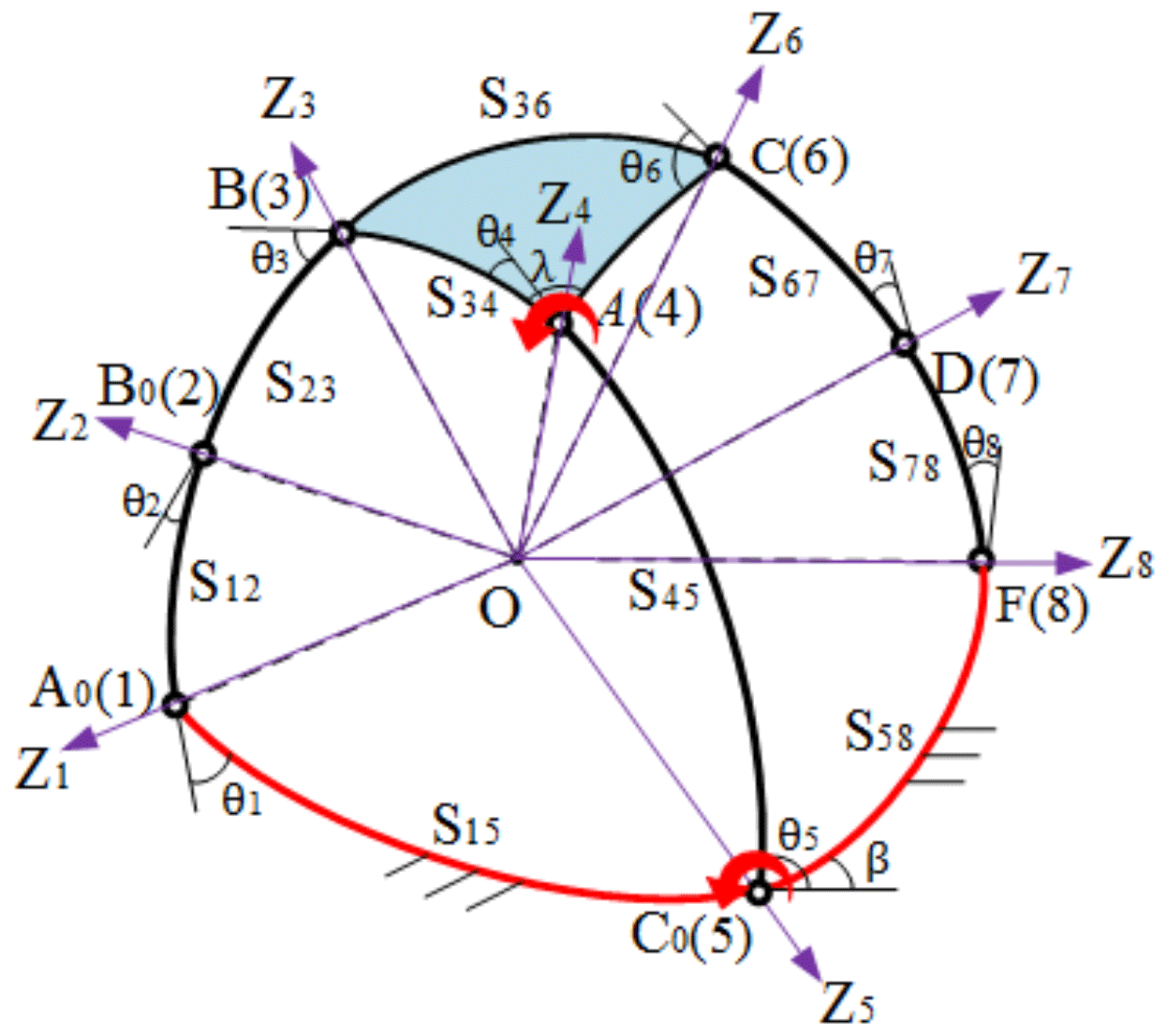
Planar parallel manipulators (PPMs) are a special case of spherical parallel manipulator. Similar to the 2 DOF seven-bar PPM, the 2 DOF seven-bar SPM has three different topologies (Duffy, 1980). In this paper, this kind of 2 DOF seven-bar SPM, which contains two spherical five-bar loops (loops A0B0BAC0 and C0ACDF), shown in Fig. 1, is studied. The symmetric loop structure (here this only means the number of links in the two spherical loops is the same, but the size may not be) has many advantages in industrial applications such as high speed and easy control. And the joints of this kind of SPM are all R joints, which are easy to manufacture and assemble.
2.1 Input joints
As is known, different input conditions lead to different mechanism motion. For 2 DOF SPM, the normal input choices are the two joints on the static frame (such as the joints A0 and C0 in Fig. 1). Under this input condition, the actuators are easily installed, and the passive links can reduce weight. However, in this study, for the sake of the formation and solution of the loop equations of the 2 DOF seven-bar SPM, the input joints are given as the joints A and C0 as shown in Fig. 1. That is, there is only one input joint placed on the static frame. Despite there being three different topologies for the 2 DOF seven-bar SPM and several different input choices, only by choosing this input condition and symmetric loop structure topology can the redundant parameters be eliminated and the branch graph containing two input angles be formed. And then, the two loop equations obtained have common real roots. For example, if the input joints are given other joints, such as normal input choices joints A0 and C0, for loop A0B0BAC0, the input angles θ1 and θ5 are still included, but for loop C0ACDF, there is only input angle θ5. According to Sects. 2.1 and 3.2, there is another redundant angle θi which cannot be eliminated, indicating that the loop equations cannot be solved. In addition, compared to the normal parallel input joints, the unusual input joints are in series in a removable link, which brings the advantages of higher reaction speed and wider input range when the output link arrives at the designated position shown in Fig. 2.
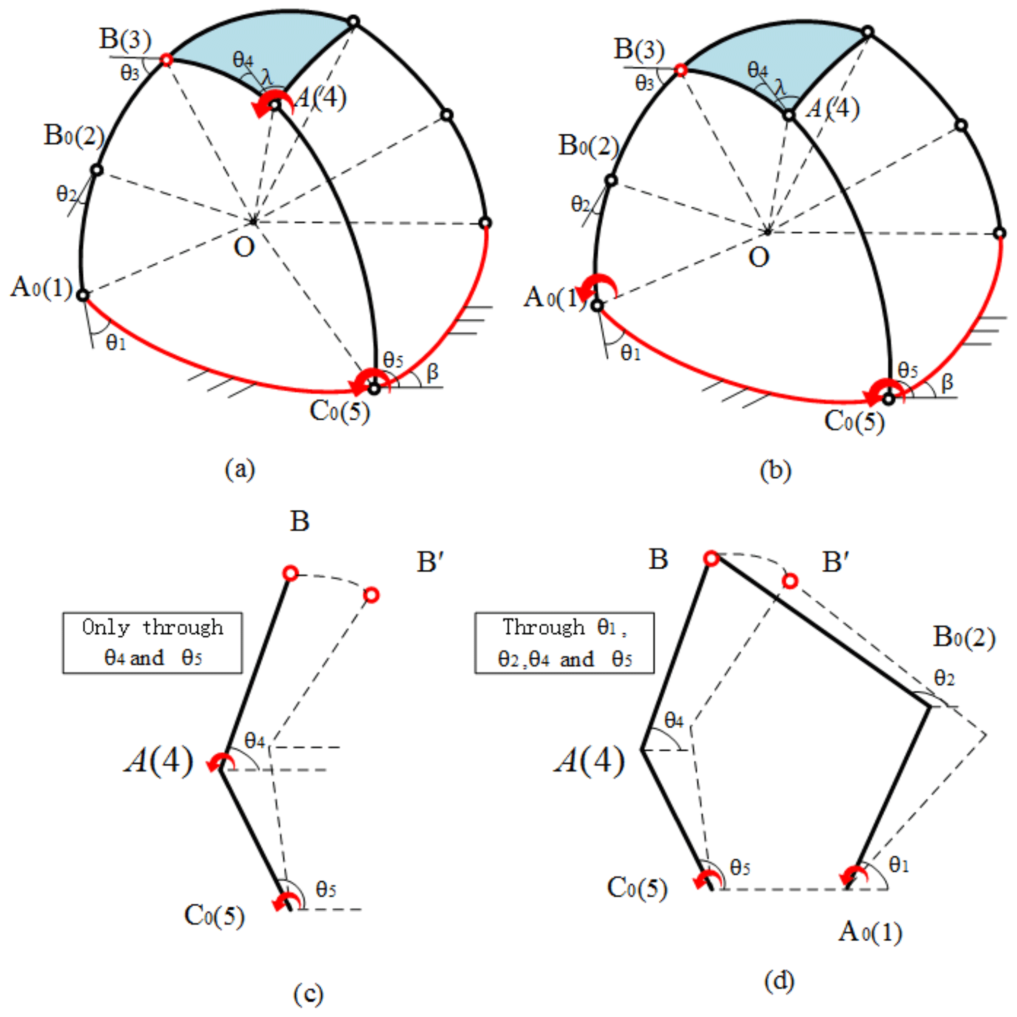
Figure 2Two kinds of input joints and corresponding motion simplification diagrams. (a) Input joints at A and C0, (b) input joints at A0 and C0, (c) motion only through θ4 and θ5 when input joints are at A and C0, and (d) motion through θ1, θ2, θ4, and θ5 when input joints are at A0 and C0.
3.1 Loop equations
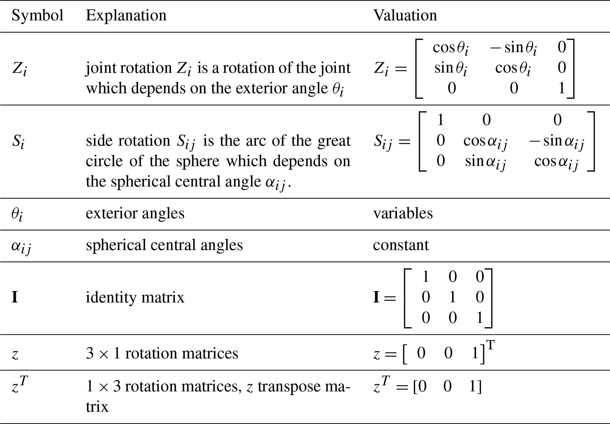
Loop equations are a common tool to analyze the kinematics of planar manipulators, which has been proved in Ting (1993), Ting and Dou (1996), and Wang et al. (2010). For a certain planar manipulator, the loop equations contain all the kinematic characteristic information, which includes the connections of the links, the input–output relationship, and the transient motion. As discussed in the Introduction, planar manipulators are special spherical manipulators. Therefore, loop equations can also be utilized to analyze the kinematics of SPMs. Two steps to establish corresponding loop equations are listed as follows. And the used symbols and corresponding explanations are shown in Table 1.

Figure 3Joint rotation and side rotation established in a spherical four-bar manipulator with only R joints.
Step 1. Set up a spherical mathematical mode by building coordinate axes at every vertex of each link. Taking a spherical four-bar manipulator (four R joints in Fig. 3) as an example, there are two kinds of rotation in the loop of the spherical four-bar manipulator: joint rotation Zi (i=1, 2, …4) and side rotation Sij (i=1, 2, 3, j=2, 3, 4) (Palpacelli et al., 2018), which appear alternately. The green ones show the side rotation and the purple ones show the joint rotation. The joint rotation Zi is defined as a rotation of the joint in which the z axis of each system is given to the axis of the rotation of joint rotation, and the x and y axes can be arbitrarily given with right-hand orthogonal coordinates (Palpacelli et al., 2018). For example, the joint rotations Z1, Z2, Z3, and Z4 are the purple centerlines, which are the pivot centerlines of adjacent articulated joints in Fig. 3. The value of the joint rotation Zi is variable, which depends on the exterior angle θi (i=1, 2, …4). It can be expressed as a matrix equation as follows.
The side rotation Sij is defined as follows. When all joint rotations Zi of the SPM are defined, the contact rotation which is between any two adjacent joint rotations is named as a side rotation Sij (Palpacelli et al., 2018). It is obvious to find that the side rotation Sij is represented by the arc of the great circle of the sphere, namely, the spherical central angle αij (i=1, 2, 3, j=2, 3, 4) between points i and j when the radius of the sphere is 1. The matrix equation of the side rotation Sij is shown as follows. Note that the side rotation Sij is commonly constant for an existing spherical manipulator.
Step 2. Build loop equations. According to the discussion above, joint rotation Zi and side rotation Sij are encountered in alternation in a loop of the spherical manipulator. So a typical loop equation can be established as follows.
where Zi and Sij are both 3 × 3 rotation matrices, and the identity matrix is called I. Equation (3) indicates that sequential rotations are compounded by matrix multiplication.
According to the foregoing setting, considering z=[0 0 1]T, the equations zTZi=zT and Ziz=z can be obtained based on the matrix operation rule. For Eq. (3), postmultiply the matrix and z on both sides of Eq. (3), and then premultiply the matrix zT. After that, Eq. (3) can be rewritten as Eq. (4), which can be further simplified as Eq. (5).
where the right-hand side of the equation is the (3,3) element of . That is, the two joint rotations Z1 and Zk have been removed; in other words, the variable elements θ1 and θk are eliminated.
3.2 Loop equations of the 2 DOF seven-bar spherical parallel manipulator
There are two spherical five-bar loops in the 2 DOF seven-bar SPM (Fig. 1): the spherical five-bar loop A0B0BAC0 and the spherical five-bar loop C0ACDF. Since the input joints are at the joints A and C0 (i.e., the input angles are θ4 and θ5), two loop equations, which contain all the kinematic information of the SPM, are shown as follows based on Eq. (3).
Loop A0B0BAC0:
Loop C0ACDF:
According to Eqs. (4) and (5), (6) and (7) can be rewritten as Eqs. (8) and (9):
Note that the exterior angles θi of the joint rotation Z4, Z5 and Z4', Z5' in Eqs. (6) and (7) are different; Z4 and Z5 correspond to the angles θ4 and θ5, which are shown in Fig. 1; however, the angles of the and are equal to (λ-θ4) and (θ5-β), respectively.
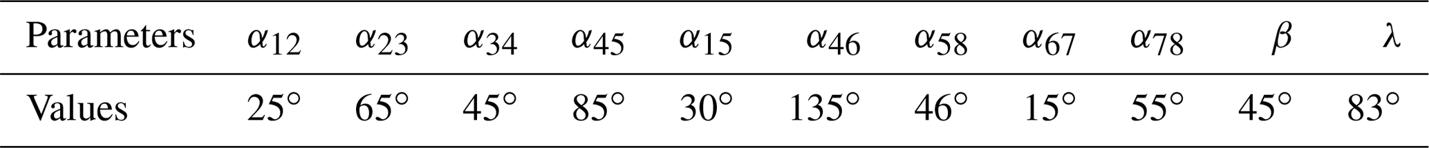
Bringing the known parameters (i.e., αij, λ, and β) into the equations, there are only three unknown angles θ1, θ4, and θ5 in Eq. (8). And three variables θ4, θ5, and θ6 are included in Eq. (9). In order to reduce the unknown parameters, the tangent half-angle formulas and discriminant method are utilized. The unknown parameters θ1 and θ6 are eliminated.
Firstly, the equations cos, sin and cos, sin (where m= tan(θ1∕2), n= tan(θ6∕2)) are respectively substituted in Eqs. (7) and (8) based on the tangent-half-angle formulas. After these changes, Eqs. (8) and (9) can be regarded as the quadratic Eqs. (10) and (11) about m and n as follows.
where ai, bi, and ci () are the coefficients in the light of θ4 and θ5, which can be obtained with Maple. The tangent half-angle formulas do not change the essence of loop equations but only the representation. Changing Eqs. (8) and (9) into Eqs. (10) and (11), the four variables θ1, θ4, θ5, and θ6 only become the four variables m, n, θ4, and θ5. But Eqs. (10) and (11) can be considered to be the dualistic equations about variables m and n.
Secondly, since the SPM should be assembled, that is, the loop equations can be established, the condition for the SPM to move is the discriminants Δi≥0 of the dualistic equations about variables m and n. Owing to Eqs. (10) and (11), the discriminant equations will only contain variables θ4 and θ5 (Eqs. 12 and 13).
The discriminant method is valid for singularity analysis, which had been proved in Wang et al. (2010). For the 2 DOF seven-bar SPM (Fig. 1), the singularity problem can also be solved based on the discriminants of two spherical five-bar loop equations.
4.1 Discriminants of two spherical five-bar loop equations
For Eqs. (10) and (11), if ai≠0, in order to guarantee that the SPM is moveable, the discriminants must satisfy
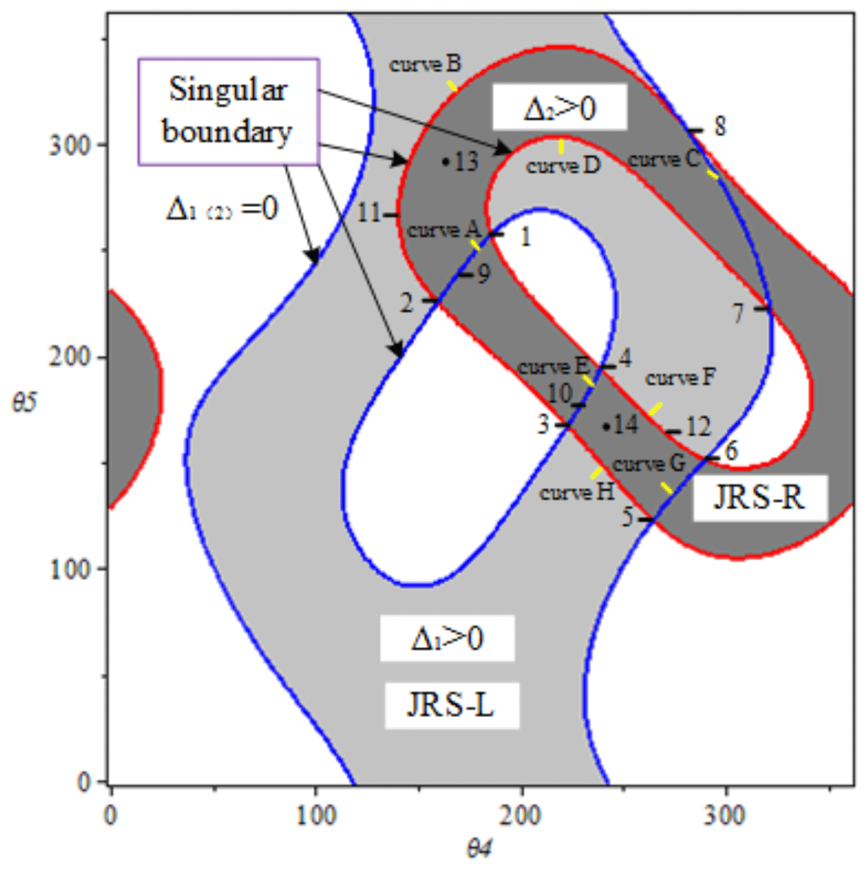
For the equations about m and n (i.e., θ1 and θ6), Eqs. (12) and (13) are the conditions of the real roots, which are also the necessary conditions that the entire manipulator should satisfy to ensure that the SPM can be assembled. In other words, only when Eqs. (12) and (13) (Δi≥0) are satisfied can the SPM exist and have research significance. And the discriminant equations are just about the angles θ4 and θ5. Using Maple, the relationship curves can be drawn, which are just the singular boundaries (Δi=0) of the spherical five-bar loops. The singular boundary is the rotation limit of the input joint. In Fig. 4, the blue curves represent the singular boundaries of the spherical five-bar loop A0B0BAC0, and the singular boundaries of the spherical five-bar loop C0ACDF are the red ones. It is worth noting that the valid singular boundaries (discussed in Sect. 4.2) of the SPM are just part of all the singular boundaries, where the SPM may momentarily lose control and has zero mechanical advantage (Gosselin and Angeles, 1990; Yan and Wu, 1989; Hunt, 1978). The valid singular boundaries are the gather of dead center positions. That is, every point of the valid singular boundaries corresponds to a singular configuration of the SPM. The corresponding parameters of spherical parallel manipulation in Fig. 4 are listed in Table 2. As for JRS-L and JRS-R (Δi>0) in Fig. 4, they are discussed in Sect. 5.1.
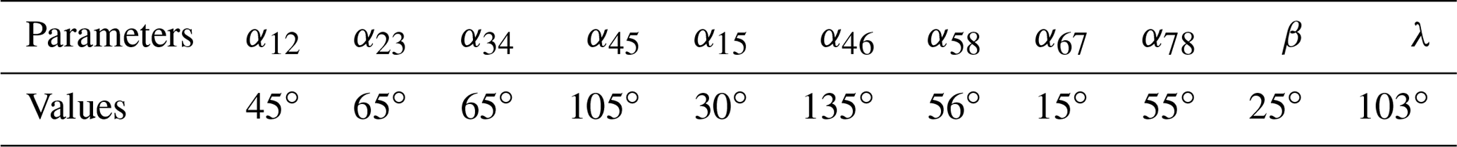
Table 2Parameters of spherical parallel manipulation in Fig. 4.
4.2 Singularity analysis
As discussed above, singularities of the 2 DOF seven-bar SPM occur when the SPM reaches valid singular boundaries. According to Eqs. (12) and (13) (Δ1≥0 and Δ2≥0), the valid singular boundaries can be obtained and divided into three categories: (a) Δ1=0, Δ2=0; (b) Δ1=0, Δ2>0; (c) Δ1>0, Δ2=0. Therefore, the singularities will also be discussed for three cases. Taking Fig. 4 as an example, for case (a), the valid singular boundaries are just the points 1, 2, 3, 4, 5, 6, 7, and 8 (i.e., singularity points), which are listed in Table 3 (also called branch points in Sect. 5.2). For case (b), the valid singular boundaries are the curves A(1-2), C(8-7), E(4-3), and G(5-6). For case (c), the curves B(2-8), D(7-1), F(6-4), and H(3-5) are the valid singular boundaries. As a consequence, singularities of the 2 DOF seven-bar SPM are the gather of the singularity points and the curves.

After the values of the variables θ4 and θ5 are acquired, the other parameters (θ1 and θ6) can be obtained by the following Eqs. (14a), (14b), (15a), and (15b), which are the results of Eqs. (10) and (11), respectively. Limited by the links' size, the rotation range of θ1 and θ6 is commonly obvious. For example, in Fig. 4, the θ1ϵ(0, π∕2), and θ6ϵ(0, π); thus, the arctan(x) only has one root, which means the corresponding singular configuration is unique. Figure 5a and 5b show singular configurations of the SPM at singularity points 1 and 2 (Fig. 4) (Δ1=0 and Δ2=0). For Fig. 5a, according to all the obtained parameters, the SPM is at the singular position when the centerlines OC, OD, and OF and OA0, OB0, and OB are simultaneously coplanar. For Fig. 5b, the singular configuration of the SPM occurs if the centerlines OC, OD, and OF and OA0, OB0 and OB are simultaneously coplanar. The points in Fig. 5c and d belong to the case Δ1=0 and Δ2>0 (points 9 and 10); the singular configuration of the SPM occurs when the centerlines OA0, OB0, and OB are coplanar in Fig. 5c or the centerlines OC, OD, and OF are coplanar in Fig. 5d. The points in Fig. 5e and f belong to the case Δ1>0 and Δ2=0 (points 11 and 12); the singular configuration of the SPM occurs when the centerlines OC, OD, and OF are coplanar in Fig. 5e or the centerlines OA0, OB0, and OB are coplanar in Fig. 5f. The points in Fig. 5g and h belong to the case Δ1>0 and Δ2>0 (points 13 and 14); there is no singular configuration.
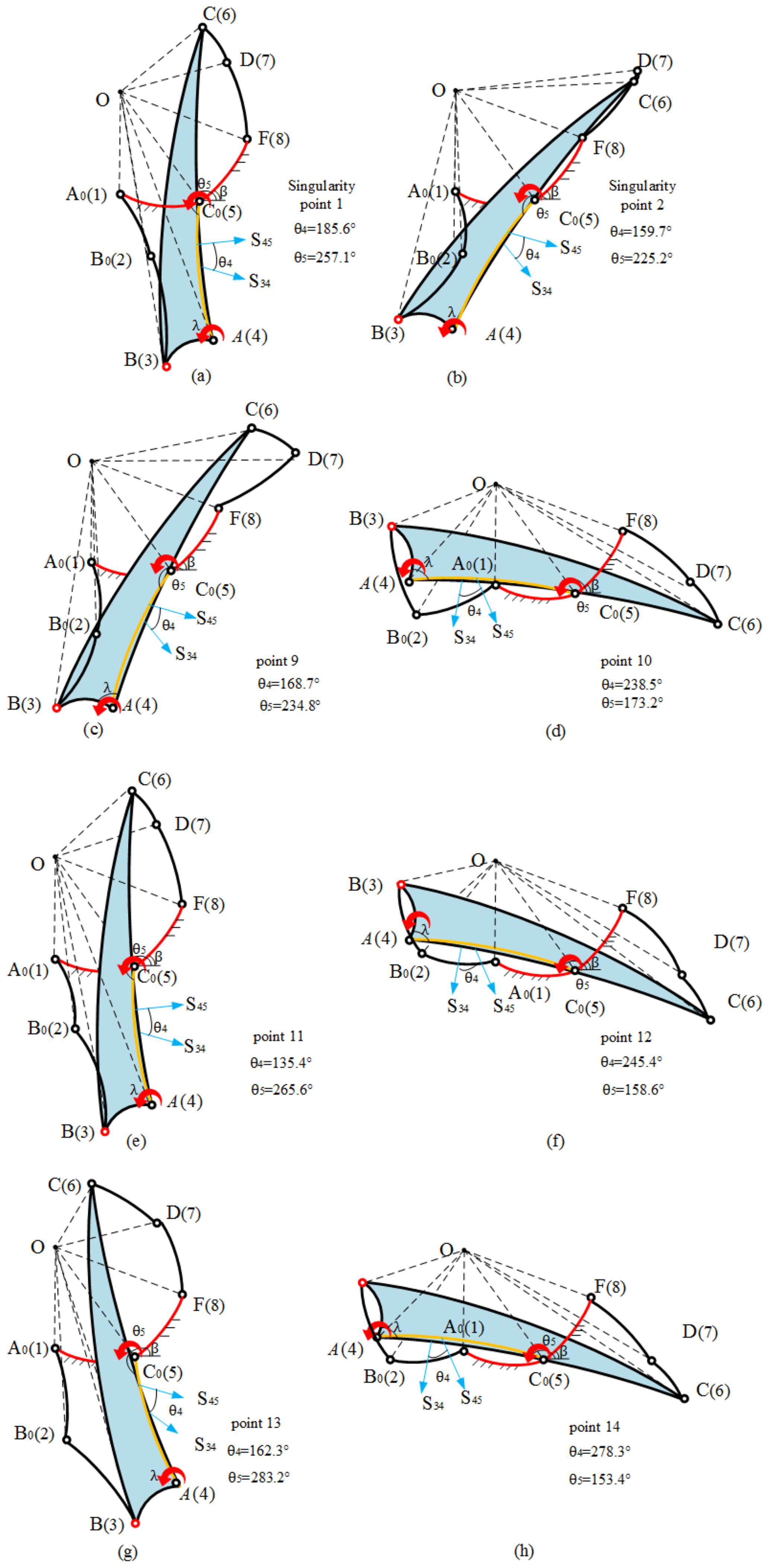
Figure 5Several configurations of the SPM. (a, b) Singularity points 1 and 2 belong to the case Δ1=0 and Δ2=0. (c, d) Points 9 and 10 belong to the case Δ1=0 and Δ2>0. (e, f) Points 11 and 12 belong to the case Δ1>0 and Δ2=0. (g, h) Points 13 and 14 belong to the case Δ1>0 and Δ2>0.
For convenience, the following steps are summarized for the singularity analysis of this kind of 2 DOF seven-bar SPM.
-
Step 1. Set up corresponding coordinate axes at every vertex of each link to get the all joint rotations Zi and side rotations Si.
-
Step 2. Establish the loop equations (Eqs. 6 and 7) of two five-bar spherical loops.
-
Step 3. Eliminate the no-input angles using the matrix multiplication and discriminant method to obtain singular boundary equations (Eqs. 12 and 13).
-
Step 4. Solve the singular boundary equations to obtain the values of input angles θinput. Then, all the unknown parameters can be given by substituting obtained θinput into the loop equations (Eqs. 6, 7, 14, and 15). After that, the singular configurations of the SPM are acquired.
A branch is an assembly configuration area in which the spherical manipulator can move continuously without meeting singularity points. The branch problem is strictly affected by the kinematic chain and is irrelevant to the input or output conditions (Ting, 1994, Ting and Dou, 1996), which means when the size of the links of the SPM is determined, the branches of this SPM are decided no matter where the input angles and output angles are chosen. Therefore, in order to meet the requirements of the input range and decoupling motion, the branches should be identified during the design stage. A branch usually contains three parts: a valid joint rotation space, a branch point, and a branch curve. The valid joint rotation space is the inner area of the branch. And the branch points and branch curves constitute the boundaries of the branch. The corresponding concepts are explained in detail in Sect. 5.1. Last but not least, the branches are not the workspace of the SPM but the effective joint rotation range which decides whether the SPM is assembled.
5.1 Joint rotation space
The joint rotation space (JRS) is a region that represents the maximum possible configuration space of the manipulators (Ting, 1994, Ting and Dou, 1996). The JRS is not the workspace and working modes of the robot but the input ranges, which is useful when the manipulator has input and security requirements. It can be obtained by discriminant equations such as Eqs. (12) and (13). The JRS is composed of the singular boundaries (Δ1=0 and Δ2=0) and the inner areas (Δ1>0 and Δ2>0), implying all mobility information of the manipulator. In a JRS, every point generally corresponds to one or more manipulator configurations. For example, in Fig. 4, the JRS of spherical five-bar loop A0B0BAC0, named JRS-L, is the light shade inner area and blue boundaries, which satisfy Eqs. (12) and (14). The dark shade inner area and red boundaries which satisfy Eqs. (13) and (15), called JRS-R, is the JRS of spherical five-bar loop C0ACDF. The JRS of the 2 DOF seven-bar SPM (Fig. 1) is decided by the two five-bar spherical loops A0B0BAC0 and C0ACDF. Therefore, the interaction JRSs of the JRS-L and JRS-R, i.e., the common JRSs 1-2-8-7 and 4-6-5-3 in Fig. 4, are the JRSs of the 2 DOF seven-bar SPM, which satisfy Eqs. (12), (13), (14), and (15) simultaneously. It is easy to find that the common JRSs are usually the branches of the SPM.
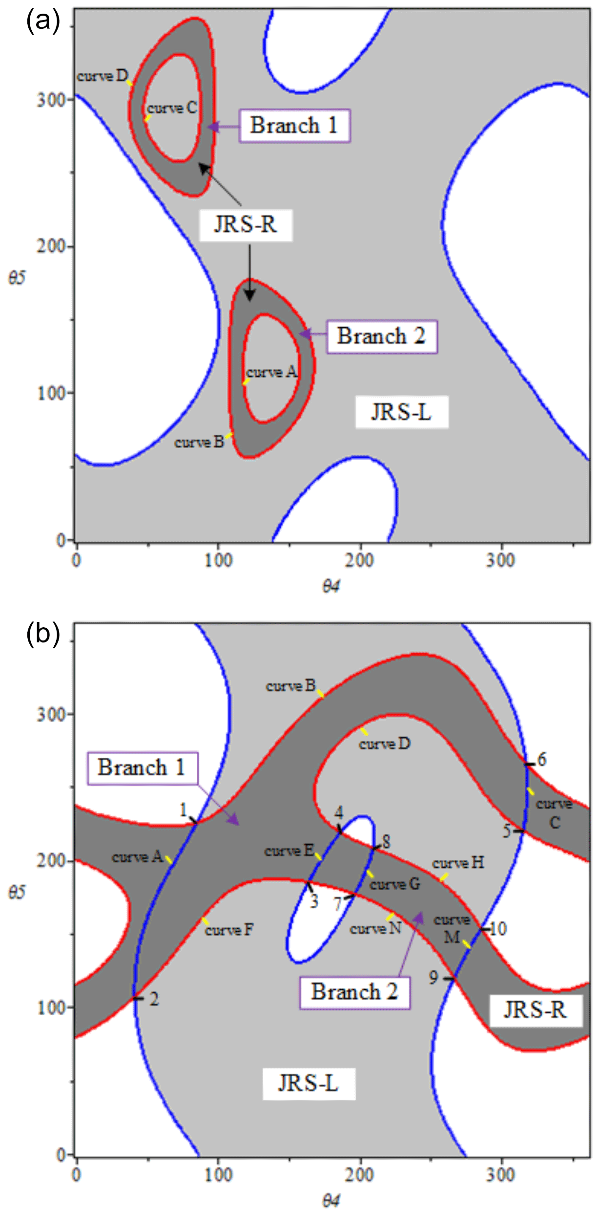
Figure 6(a) Branch graph of the 2 DOF seven-bar spherical manipulator without branch points. (b) Branch graph of the 2 DOF seven-bar spherical manipulator with branch points.

5.2 Branch point and branch curve
-
Branch point. The branch point (Ting, 1994, Ting and Dou, 1996) is a singularity point which is the intersection point of the two singular boundaries of the two spherical loops (i.e., Δ1=0, Δ2=0), discussed in Sect. 4.2. At these branch points, the SPM may lose control momentarily and has zero mechanical advantage. The branches are usually surrounded by the branch points, such as points 1, 2, 8, and 7 in the branch 1-2-8-7 in Fig. 4. Branch points are not only used as the characteristic points which differentiate separated branches of the spherical manipulators but are also applied to classify the types of branches of the SPM according to whether branch points exist. Different types of the branches affect the coupling motion of the SPM, which is explained in detail in Sect. 5.3.
-
Branch curve. Branch curves cover branches, which are often valid segments of singular boundaries (Dou and Ting, 1996) satisfying Eq. (12) or Eq. (13) (i.e., Δ1=0 or Δ2=0). As mentioned above, branch curves and branch points separate different branches. In Fig. 4, the curves A (1-2), B(2-8), C(8-7), D(7-1), E(4-3), H(3-5), G(5-6), and F(6-4) are the branch curves.
5.3 Two types of branches
To consider whether the branch points exist, the branches of the 2 DOF seven-bar SPM can be classified into two types as follows.
- 1.
Type I. No branch point exists. The mobility is only affected by one spherical five-bar loop; that is, the motion of the 2 DOF seven-bar SPM is decoupled.
Explanation. There is no branch point in the type I branch of the 2 DOF seven-bar SPM, which means Eqs. (12) and (13) (Δ1=0 and Δ2=0) have no common results. In other words, one of the JRSs of the two spherical loops is covered by another, such as the JRS-R, which is enclosed by the JRS-L in Fig. 6a (Fig. 6a is the result of Example 1 in Sect. 6). Thus, the JRS-R is just the common JRS of the 2 DOF seven-bar SPM. To some extent, the motion of the SPM is only determined by one spherical loop; i.e., it is decoupled.
- 2.
Type II. Branch points exist. The branches are affected not only by the two spherical five-bar loops but also the interaction between them. The motion of the 2 DOF seven-bar SPM is coupled.
Explanation. For the type II branch of the 2 DOF seven-bar SPM, branch points exist; that is, the branches of the 2 DOF seven-bar SPM are determined by the interaction between the two JRSs of the two five-bar spherical loops. Satisfying Eqs. (12) and (13), the common JRSs are overlapping areas and covered by the branch points and the branch curves. In Fig. 6b (Fig. 6b is the result of Example 2 in Sect. 6), the singularity points 1, 2, 3, 4, 5, 6, 7, 8, 9, and 10 are branch points. And these branch points and branch curves wrap two branches which are decided by the JRS-L and JRS-R, that is, the branches 1 and 2. The obtained branches decide the coupled motion of the SPM.
It is worth noting that Fig. 6a is also regarded as a circuit problem, and Fig. 6b is still a branch problem in Norton (2004).
5.4 Process of branch analysis
As a result of the discussion above, the following steps for branch identification of the 2 DOF seven-bar SPM can be summarized.
- 1.
JRS of two five-bar spherical loops. Draw the branch graph using Eqs. (12) and (13) in Maple, and obtain two JRSs of the two five-bar spherical loops.
- 2.
Branch points. Save the equations Δ1=0 and Δ2=0; if the roots can be obtained, the branches of the SPM are Type II, and the roots are just branch points of the 2 DOF seven-bar SPM. If not, they are Type I.
- 3.
Branch curves. Get the valid curves of the singular boundaries according to the corresponding equations Δ1=0, Δ2>0 or Δ1>0, Δ2=0.
- 4.
Branch identification. Acquire the common JRS based on the results above. The common JRSs are covered with branch points and branch curves, which are also just the branch(es) of the 2 DOF seven-bar SPM. In a branch, every point represents one mechanical configuration, and the mechanical configuration in different branches can not transfer unless the SPM is reassembled.
In short, different types of branches are suited to different performance applications. When the SPM needs a decoupled motion, the Type I branch is the right choice. When a coupling motion is required, the Type II branch is applicable. As for the input requirements, it is obvious to see that different branches have a different corresponding input range; suitable branches can be selected according to design demand.
Example 1. The dimensions for branch identification of the 2 DOF seven-bar SPM are shown in Table 4.
Using the given parameters, the branches of the 2 DOF seven-bar SPM are shown in Fig. 6a using Maple. It is obvious to find that the branches are Type I. The process of identification is shown as follows.
- 1.
JRS of two five-bar spherical loops. The JRS-L, the light gray area and blue boundaries, is the JRS of the five-bar spherical loop A0B0BAC0 which is determined by Eq. (12). The JRS-R is shown by the dark gray areas and red boundaries (Fig. 6a). They are determined by Eq. (13).
- 2.
Branch points. There is no solution between the equations Δ1=0 and Δ2=0. Thus, no branch point exists.
- 3.
Branch curves. The JRS-R stays inside the JRS-L, which means the branches of the 2 DOF seven-bar SPM are only decided by JRS-R. In other words, the branch curves are the singular curves of JRS-R, i.e., the curves A, B, C, and D, which satisfy the equations Δ1>0, Δ2=0.
- 4.
Branch identification. According to the foregoing results, the common JRS are the JRS-R. And there are two branches in JRS-R, i.e., branches 1 and 2 as shown in Fig. 6a.
Discussion. The SPM in Example 1 has the character of decoupled motion and two different branches. It applies to the motion of the SPM decided by only one spherical loop. And branch 1 has the input ranges θ4ϵ (38.2∘, 90.3∘) and θ5ϵ (228.5∘ , 355.1∘). Branch 2 has the input ranges θ4ϵ (112.7∘, 168.6∘) and θ5ϵ (52.3∘, 175.6∘). The two branches have different corresponding input ranges; suitable branches can be selected according to design demand.
Example 2. The other dimensions of the 2 DOF seven-bar spherical manipulator are given in Table 5.
Based on the given dimensions above, the branches of the 2 DOF seven-bar SPM are shown in Fig. 6b with Maple. Since the branch points exist in this case, the branches are Type II. The following steps are used to identify the branches.
-
JRS of two five-bar spherical loops. The JRS-L, the light gray area and blue boundaries, is the JRS of the five-bar spherical loop A0B0BAC0. It is determined by Eq. (12). The JRS-R is shown by the dark gray area and red boundaries (Fig. 6b), which is determined by Eq. (13).
-
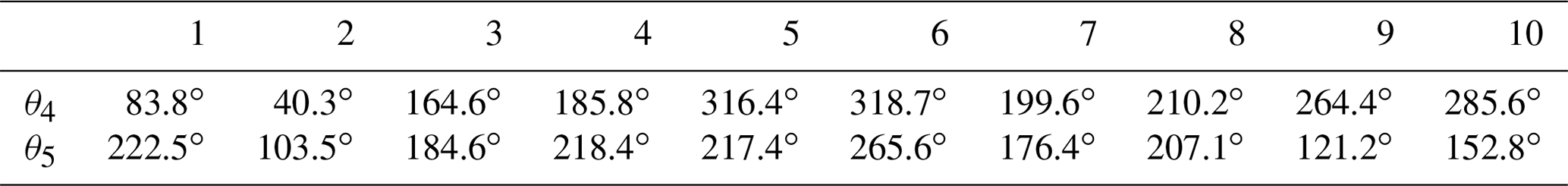
Branch points. There are 10 roots between the equations Δ1=0 and Δ2=0. Each root represents a branch point, which is listed in Table 6.
-
Branch curves. Branch curves are valid segments of the singular curves, which are defined by the equations Δ1=0, Δ2>0 and Δ1>0, Δ2=0. For Fig. 6b, the curves A, B, C, D, E, F, G, H, M, and N are branch curves.
-
Branch identification. According to the foregoing results, the common JRSs of the SPM are the overlapping areas of JRS-R and JRS-L, that is, the two areas 1-A-2-F-3-E-4-D-5-C-6-B and 8-G-7-N-9-M-10-H, which are covered by branch points 1, 2, 3, 4, 5, 6, 7, 8, 9, and 10 and branch curves A, B, C, D, E, F, G, H, M, and N. In other words, there are two branches in the 2 DOF seven-bar SPM, i.e., branches 1 and 2, as shown in Fig. 6b.
Discussion. The motion of the SPM in Example 2 is coupled. The SPM applies to the motion of the SPM determined by two spherical loops. There are two branches: branch 1 and branch 2. Branch 1 has the input ranges θ4ϵ (41.7∘, 315.4∘) and θ5ϵ (101.3∘, 332.1∘). Branch 2 has the input ranges θ4ϵ (198.4∘, 273.6∘) and θ5ϵ (105.8∘, 215.4∘). The input ranges of branch 2 are contained by branch 1.
According to the concept of joint rotation space and the discriminants of two five-bar spherical loops, this paper utilizes the branch graph, which depends on loop equations to identify singularities and branches of a kind of 2 DOF seven-bar SPM. Compared to other literature, there are four advantages shown as follows.
The presented 2 DOF seven-bar SPM which only contains two spherical five-bar loops is the main contribution. The highlights of this SPM are the unusual active choices and the symmetric loop structure. On the one hand, they solve the variable problem of loop equations with the discriminant method; on the other hand, they lead to the advantages of high reaction speed, wide input range, easy control, and high rigidity, which are more often required in industry compared to other SPMs. Thus, it may offer a new structure for industry applications such as cardans, robot wrists, camera-orientating devices, and even sensors.
Singularities and branches of a kind of 2 DOF seven-bar SPM were identified first.
Based on the branch graph, the proposed method is succinct and visual. It offers a geometric insight into understanding the formation of mobility information and is especially useful when the SPM has a specific input range or branch choice.
Two types of branches of the 2 DOF seven-bar SPM are distinguished according to whether branch points exist. Different branches correspond to the different coupling motions of the spherical mechanism.
The data in this study can be requested from the corresponding author.
LN, HD, and AK conducted the numerical analyses and wrote the majority of the paper. HD and JG supervised the findings and organized and structured the paper. JW and KT reviewed the paper and gave constructive suggestions to improve the quality of the paper.
The authors declare that they have no conflict of interest.
The first author would like to thank those who have hurt him over the years; they have made him stronger. In addition, he thanks the topical editor, Giuseppe Carbone, and the reviewers Iosif Birlescu and two anonymous referees, whose hard work improved the quality of the paper.
This research has been supported by the Natural Science Foundation of China (nos. 51975544, 51805494, and 51675495), the Major Project of Hubei Province Technology Innovation (grant no. 2019AAA071), and the 111 Project (grant no. B17040).
This paper was edited by Giuseppe Carbone and reviewed by Iosif Birlescu and two anonymous referees.
Bai, S., Hansen, M. R., and Angeles, J.: A robust forward-displacement analysis of spherical parallel robots, Mech. Mach. Theory, 44, 2204–2216, 2009.
Bai, S., Li, X., and Angeles, J.: A review of spherical motion generation using either spherical parallel manipulators or spherical motors, Mech. Mach. Theory, 140, 377–388, https://doi.org/10.1016/j.mechmachtheory.2019.06.012, 2019.
Boscariol, P., Gasparetto, A., and Scalera, L.: Efficient closed-form solution of the kinematics of a tunnel digging machine, J. Mech. Rob., 9, 1–13, https://doi.org/10.1115/1.4035797, 2017.
Chase, T. R. and Mirth, J. A.: Circuits and branches of single degree-of-freedom planar linkages, J. Mech. Des. Trans. ASME, 115, 223–230, https://doi.org/10.1115/1.2919181, 1993.
Danaei, B. and Arian, A.: Tale Masouleh M, Kalhor A, Dynamic modeling and base inertial parameters determination of a 2-DOF spherical parallel mechanism, Multibody Syst. Dynam., 41, 367–390, https://doi.org/10.1007/s11044-017-9578-3, 2018.
Davis, H. P. and Chase, T. R.: Stephenson chain branch analysis: four generic stationary configurations and one new linkage polynomial, in: Proceedings of the 1994 ASME Design Technical Conferences, 11–14 September, Vol. 70, . 359–367, 1994.
Di Gregorio, R.: Analytical method for the singularity analysis and exhaustive enumeration of the singularity conditions in single-degree-of-freedom spherical mechanisms, Proc. Inst. Mech. Eng. Pt. C, 227, 1830–1840, https://doi.org/10.1177/0954406212469328, 2018.
Dou, X. H. and Ting, K. L.: Branch analysis of geared five-bar chains, J. Mech. Des., 118, 384–389, https://doi.org/10.1115/1.2826897, 1996.
Duffy, J.: Analysis of Mechanisms and Robot Manipulators, John Willey and Sons, New York, 56–58, 1980.
Gosselin, C. and Angeles, J.: Singularity Analysis of Closed-Loop Kinematic Chains, IEEE Trans. Rob. Autom., 6, 281–290, 1990.
Duan, X., Yang, Y., and Cheng, B.: Modeling and analysis of a 2-DOF spherical parallel manipulator, Sensors, 16, 1848, https://doi.org/10.3390/s16091485, 2018.
Elgolli, H., Houidi, A., Mlika, A., and Romdhane, L.: Analytical analysis of the dynamic of a spherical parallel manipulator, Int. J. Adv. Manuf. Technol., 101, 859–871, https://doi.org/10.1007/s00170-018-2939-0, 2019.
Gosselin, C. M. and Hamel, J. F.: Agile eye: A high-performance three-degree-of-freedom camera-orienting device, in: Proceedings of the 1994 IEEE International Conference on Robotics and Automation, 8–13 May, 1, 781–786, https://doi.org/10.1109/ROBOT.1994.351393, 1994.
Hernandez, S., Bai, S., and Angeles, J.: The desion of a chain of spherical Stephenson mechanisms for a gearless robotic pitch-roll wrist, J. Mech. Des. Trans ASME, 128, 422–429, https://doi.org/10.1115/1.2167653, 2006.
Hunt, K. H.: Kinematic Geometry of Mechanism, Oxford University Press, USA, 112–115, 1978.
Kong, X. and Gosselin, C. M.: Type Synthesis of 3-DOF Spherical Parallel Manipulators Based on Screw Theory, J. Mech. Des. Trans. ASME, 126, 101–108, https://doi.org/10.1115/1.1637655, 2004.
Li, T. and Payandeh, S.: Design of spherical parallel mechanisms for application to laparoscopic surgery, Robotica, 20, 133–138, https://doi.org/10.1017/S0263574701003873, 2002.
Liu, Y. W. and Ting, K. L.: Rotatability laws for spherical n-bar kinematic chains, in: 22nd Biennial Mechanisms Conference, 13–16 September, Vol. 46, 387–394, 1992.
Mirth, J. A.: Circuit rectification for four precision position synthesis of four-bar and watt six-bar linkages, J. Mech. Des. Trans. ASME, 117, 612–619, https://doi.org/10.1115/1.2826729, 1995.
Mirth, J. A. and Chase, T. R.: Circuit analysis of watt chain six-bar mechanisms, J. Mech. Des. Trans. ASME, 115, 214–222, https://doi.org/10.1115/1.2919180, 1993.
Nelson, C. A., Laribi, M. A., and Zeghloul, S.: Optimization of a Redundant Serial Spherical Mechanism for Robotic Minimally Invasive Surgery, Comp Kine, 126–134, https://doi.org/10.1007/978-3-319-60867-9_15, 2018.
Nie, L. and Wang, J.: Branch identification of spherical six-bar linkages, in: Proceedings of ASME 2018 International Design Engineering Technical Conferences and Computers and Information in Engineering Conference, 21–24 August, V05BT07A072, https://doi.org/10.1115/DETC2016-59018, 2018.
Norton, R. L.: Design of machinery: an introduction to the synthesis and analysis of mechanisms and machines, Boston, McGraw-Hill Higher Education, 191 pp., 2004.
Palpacelli, M., Palmieri, G., Carbonari, L., and Corinaldi, D.: Sensitivity Analysis and Model Validation of a 2-DoF Mini Spherical Robot, J. Intell. Rob. Syst. Theor. Appl., 91, 155–163, https://doi.org/10.1007/s10846-017-0679-2, 2018.
Ruth, D. A. and McCarthy, J. M.: Design of spherical 4R linkages for four specified orientations, Mech. Mach. Theory, 34, 677–692, https://doi.org/10.1016/S0094-114X(98)00048-2, 1999.
Sancisi, N., Parenticastelli, V., and Baldisserri, B.: Validation of a one degree – of – freedom spherical model for kinematics analysis of the human ankle joint, J. Foot Ankle Res., 5, 13 pp., https://doi.org/10.1186/1757-1146-5-S1-P13, 2017.
Sun, J., Liu, W., and Chu, J.: Synthesis of spherical four-bar linkage for open path generation using wavelet feature parameters, Mech. Mach. Theory, 128, 33–46, https://doi.org/10.1016/j.mechmachtheory.2018.05.008, 2018.
Ting, K. L.: Mobility criteria of single-loop N-bar linkages, J. Mech. Transm. Autom. Des., 111, 504–507, https://doi.org/10.1115/1.3259029, 1989.
Ting, K. L.: Branch and dead position problems of N-bar linkages, in: 14th Biennial Conference on Mechanical Vibration and Noise, 19–22 September, Vol. 65, 459–465, 1993.
Ting, K. L.: Mobility criteria of geared five-bar linkages, Mech. Mach. Theory, 29, 251–264, https://doi.org/10.1016/0094-114X(94)90034-5, 1994.
Ting, K. L.: On the input joint rotation space and mobility of linkages, J. Mech. Des. Trans. ASME, 130, 923031–9230312, https://doi.org/10.1115/1.2943299, 2008.
Ting, K. L. and Dou, X. H.: Classification and branch analysis of Stephenson Six-bar Chains, Mech. Mach. Theory, 31, 283–295, https://doi.org/10.1016/0094-114X(95)00075-A, 1996.
Ting, K. L. and Liu, Y. W.: Rotatability laws for N-bar kinematic chains and their proof. J Mech Des, Trans. ASME, 113, 32–39, https://doi.org/10.1115/1.2912747, 1991.
Ting, K. L., Wang, J., Xue, C., and Currie, K. R.: General mobility identification and rectification of watt six-bar linkages, in: 2007 ASME International Design Engineering Technical Conferences and Computers and Information in Engineering Conference, 4–7 September, 8, 439–448, https://doi.org/10.1115/DETC2007-34584, 2008.
Ting, K. L., Wang, J., Xue, C., and Currie, K. R.: Full rotatability and singularity of six-bar and geared five-bar linkages, J. Mech. Robot., 2, 1–9, https://doi.org/10.1115/1.4000517, 2010.
Wampler, C. W.: Displacement Analysis of Spherical Mechanisms Having Three or Fewer Loops, J. Mech. Des. Trans. ASME, 126, 93–100, https://doi.org/10.1115/1.1637653, 2004.
Wang, J., Ting, K. L., and Xue, C.: Discriminant method for the mobility identification of single degree-of-freedom double-loop linkages, Mech. Mach. Theory, 45, 740–755, https://doi.org/10.1016/j.mechmachtheory.2009.12.004, 2010.
Wu, G. and Bai, S.: Design and kinematic analysis of a 3-RRR spherical parallel manipulator reconfigured with four–bar linkages, Rob. Comput. Integr. Manuf., 56, 55–65, https://doi.org/10.1016/j.rcim.2018.08.006, 2019.
Yan, H. S. and Wu, L. L.: On the dead-center positions of planar linkage mechanisms, J. Mech. Des. Trans. ASME, 111, 40–46, 1989.
Yang, Z. F. and Xu, L. J.: Synthesis of spherical six-bar path generation mechanisms, J. Sichuan University (Engineering Science Edition), 32, 48–50, 2005.
- Abstract
- Introduction
- The 2 DOF seven-bar spherical parallel manipulator
- Kinematics of spherical manipulators
- Singularity analysis of the 2 DOF seven-bar spherical parallel manipulator
- Branch analysis of the 2 DOF seven-bar spherical parallel manipulator
- Examples
- Conclusions
- Data availability
- Author contributions
- Competing interests
- Acknowledgements
- Financial support
- Review statement
- References