the Creative Commons Attribution 4.0 License.
the Creative Commons Attribution 4.0 License.
 | 12 Oct 2020
Investigation of drilling 2D Cf∕C–SiC composites with brazed diamond core drills
Qiong Liu
Guoqin Huang
Yongchao Xu
Drilling carbon fiber reinforced silicon carbide composites still forms a big challenge for machining because of their special braided structure and anisotropy. In this study, through the drilling of 2D Cf∕C–SiC composites, two kinds of brazed diamond core drills with different abrasive distributions were compared. The results showed that the drilling force and torque of the two drills decreased with the increase in the spindle speed and increased with the increase in the feed speed. Under the same drilling conditions, the drilling force and torque of the brazed diamond drill with the ordered abrasive distribution were far lower than those of the brazed diamond drill with the random abrasive distribution. Also, the quality of the holes drilled by the drill with the ordered abrasive distribution was better than that of the holes drilled by the drill with the random abrasive distribution, which is attributed to the uniform abrasive spacing provided by the drill with the ordered abrasive distribution.
- Article
(1812 KB) - Full-text XML
- BibTeX
- EndNote


Carbon fiber reinforced silicon carbide (Cf∕C–SiC) is a ceramic matrix composite with silicon carbide as the matrix and carbon fiber as the reinforcement. Due to its low density, high-temperature oxidation resistance, corrosion resistance, and other excellent mechanical properties, it has been widely used in the aerospace industry, braking systems, precision parts, and other fields (Singh et al., 2012; Mei et al., 2014; Zhang et al., 2011). It is also a new type of high-temperature structural material and functional material that can meet the high-temperature requirement of 1650∘ (Wang et al., 2012; Yu et al., 2013). Grinding and drilling are the most common machining methods in industrial production. The 2D Cf∕C–SiC composite is difficult processing material for anisotropic and inhomogeneous structures, which limit its wide application in many industrial fields (Tawakoli and Azarhoushang, 2011; Ding et al., 2017). Many studies have been conducted on the grinding of this material (Liu et al., 2012; Cao et al., 2013; Zhang et al., 2016). Also, the grinding mechanism of the composite was studied from different fiber angles and different fiber orientations (Liu et al., 2017, 2018; Feng et al., 2017). In drilling, cemented carbide, high-speed steel, and other drilling tools are widely used as traditional tools (Wang et al., 2013; Xing et al., 2017); however, the drilling quality of carbon fiber reinforced ceramic matrix composites is very poor. Due to the high hardness and brittleness of 2D Cf∕C–SiC composites, carbon fiber tearing and delamination can easily occur in drilling processes. With the wide application of diamond tools, diamond bits are becoming more and more popular (Ding et al., 2014; Feng et al., 2017). Thus, in this study, the feasibility of drilling such kinds of composite materials was investigated, where the self-made brazed diamond bit was used with different abrasive distributions. A useful guideline which has important scientific and practical significance can be provided to optimize their structures and processability.
In this study, a 2D Cf∕C–SiC composite as the workpiece material and two brazed diamond core drills were selected, where the random arrangement and the orderly arrangement of the diamond abrasive distribution bit were tested, and their drilling characteristics, including the drilling force, torque, and hole exit quality, were compared. Together with the drilling chip analysis, the drilling mechanism was also discussed.
2.1 Workpiece
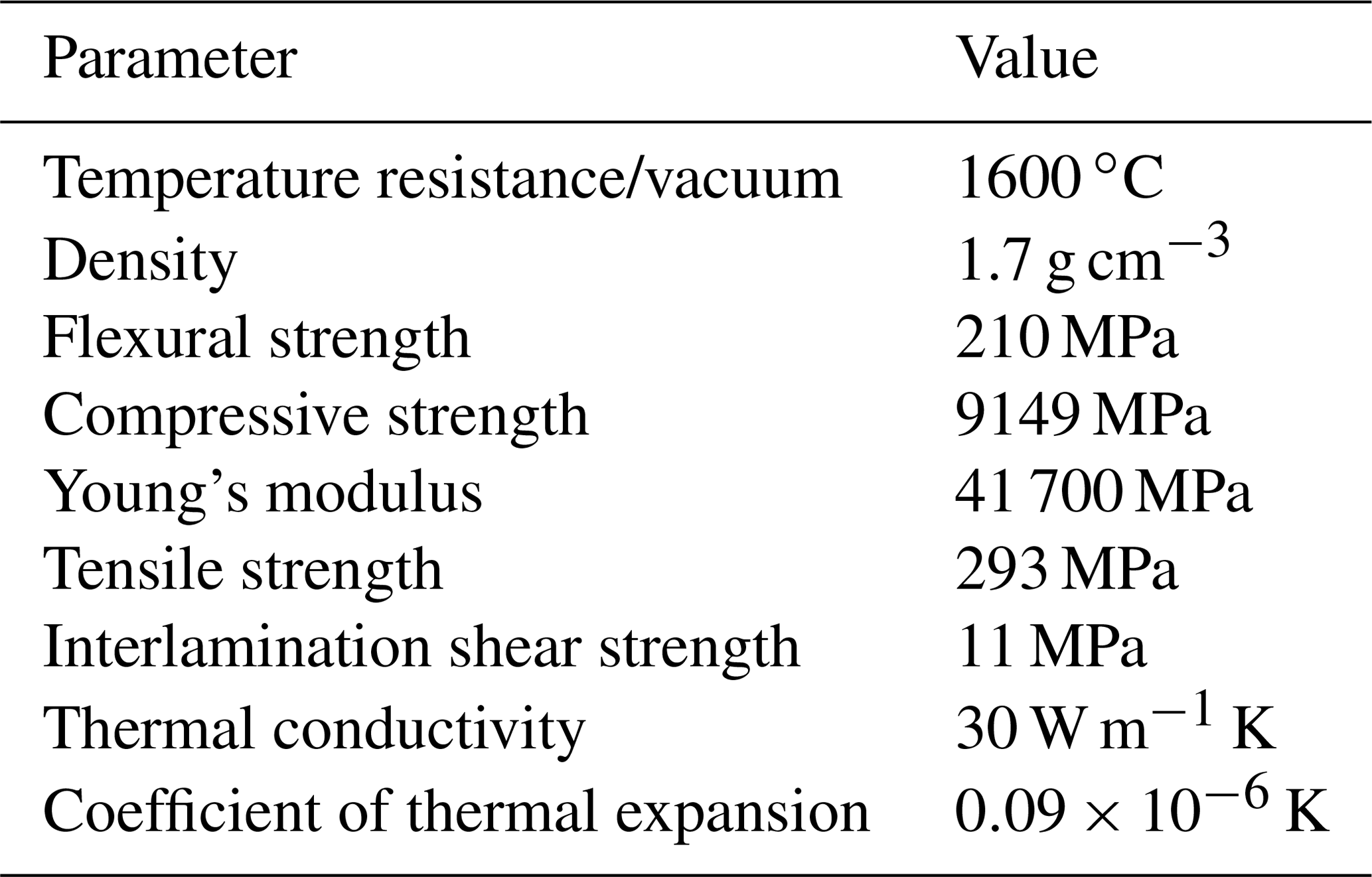
As schematically shown in Fig. 1, the 2D Cf∕C–SiC composite used in this work is a sheet laminated by 2D layers in which 0 and 90∘ carbon fiber bundles are orthogonally woven. The thickness of each laminated layer is about 100 µm. The main components of this composite include carbon fiber, silicon carbide, a carbon matrix, as well as a pyrolytic carbon interface, and its mechanical properties are shown in Table 1. For the drilling experiment, the composite sheet was cut into samples with dimensions of 50 mm (length) × 50 (width) × 3 mm (thickness).

Table 1Mechanical properties of the 2D Cf∕C–SiC material at room temperature.
2.2 Drill setup and brazed diamond core drills
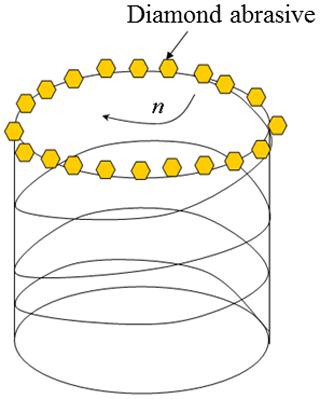
Drilling experiments were carried out on a vertical machining center (HAAS OM2, USA) with a maximum spindle speed (n) of 30000 r min−1. The drill setup is shown in Fig. 2a, and the schematic diagram of the core drill is shown in Fig. 2b. The 2D Cf∕C–SiC workpiece was directly clamped on a borehole dynamometer (9272, Kistler, Switzerland) installed on the machine table. During drilling, in order to prevent measurement errors, the bit was always kept above the center hole of the dynamometer. As seen in Fig. 1, the drilling direction of the workpiece is perpendicular to the XOY surface plane. A series of drilling experiments were performed on the 2D Cf∕C–SiC composites to collect tearing defect data, and the drilling parameters are listed in Table 2. Dry drilling was adopted for drilling, and for each combination of parameters, the force measurement was repeated three times to obtain the averaged value.
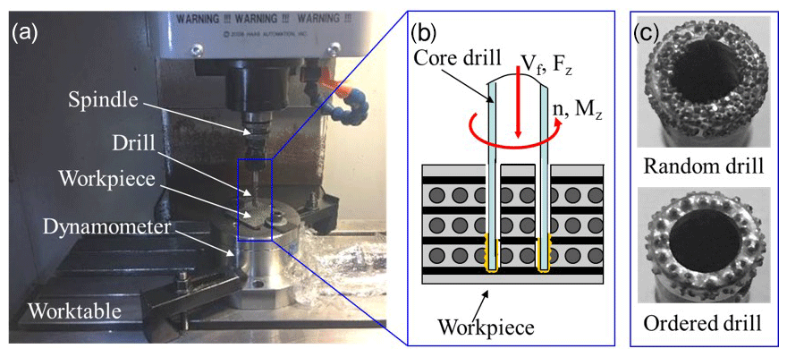
Figure 2Drill details: (a) experimental setup, (b) diagram of drilling, and (c) brazed diamond core drills.
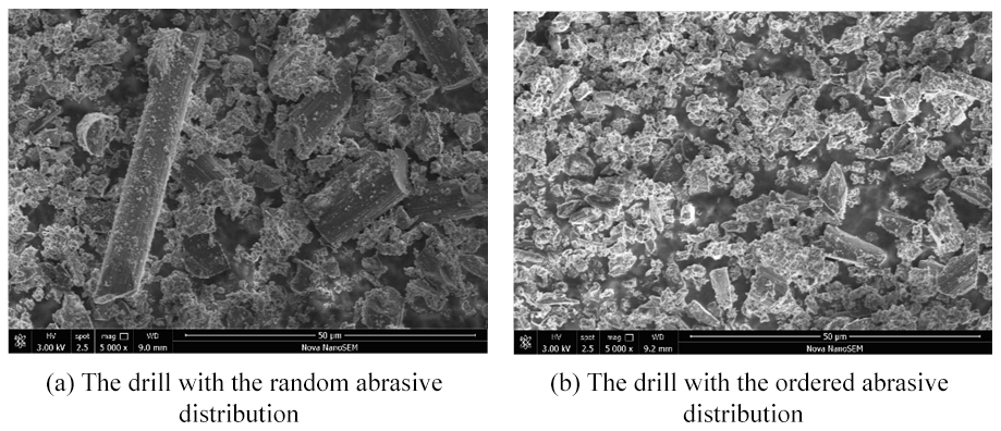
Two brazed diamond core drills with different abrasive distributions were used. As shown in Fig. 2c, the diamond grains on one of them are in random distribution and are in ordered distribution on the other one. For both drills, the size of each diamond grain is 80 cm. The grain diameter is about 160–200 µm), and the length and diameter of the drill are 70 and 6 mm, respectively.
2.3 Surface observations
A scanning electron microscope (SEM, Hitachi S-3400N, Japan) and a digital optical microscope (VHX-1000, Keyence, Japan) were employed to examine the morphologies of the drilled holes.
3.1 Drill force and torque
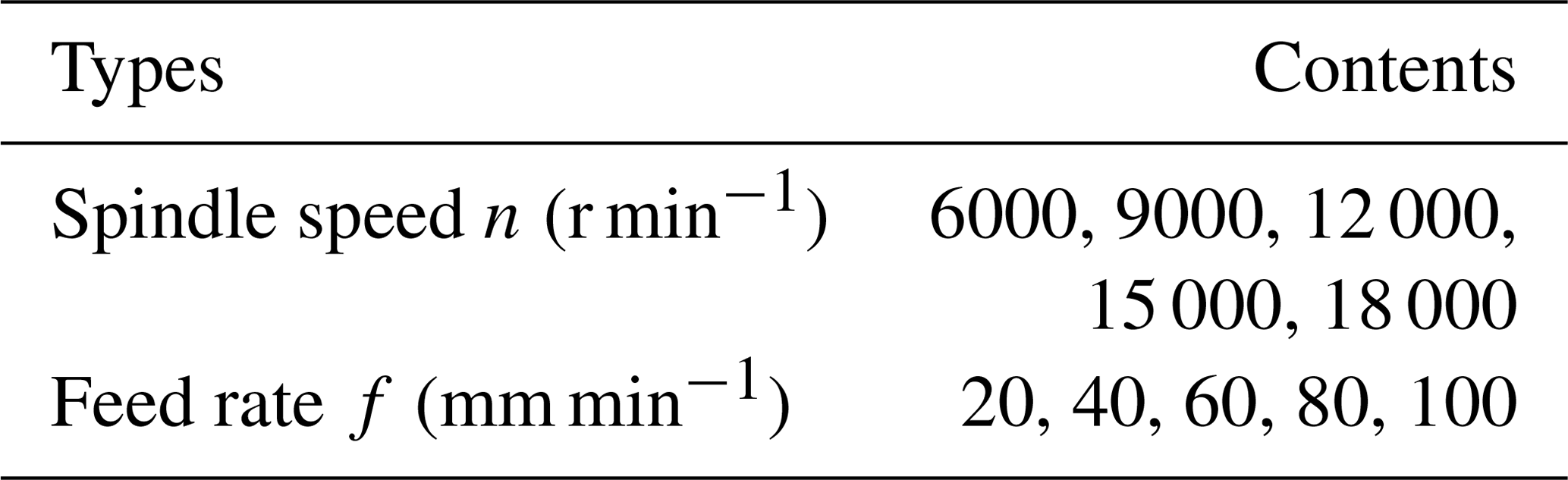
Figure 3 shows comparisons of the monitored force and torque values during the whole drilling process. Generally, both the force and torque curves of the brazed diamond drill with the ordered abrasive distribution were lower and more stable than those of the brazed diamond drill with the random abrasive distribution.
Due to the particularity of the material structure, it belongs to the layered braided structure. Therefore, during the drilling process, from the first contact with the workpiece until the end of drilling, the whole drilling process was not as stable as with metal, and it fluctuated up and down. The drilling force and torque diagram includes the instantaneous impact area and the stable drilling area. The moment of contact between the bit and the workpiece belonged to the instantaneous impact area, where the drilling force and moment were largest. Then, they gradually became stable until the workpiece was totally drilled and the drilling force and moment became 0. In this study, the average values of the stable drilling force and torque were recorded.
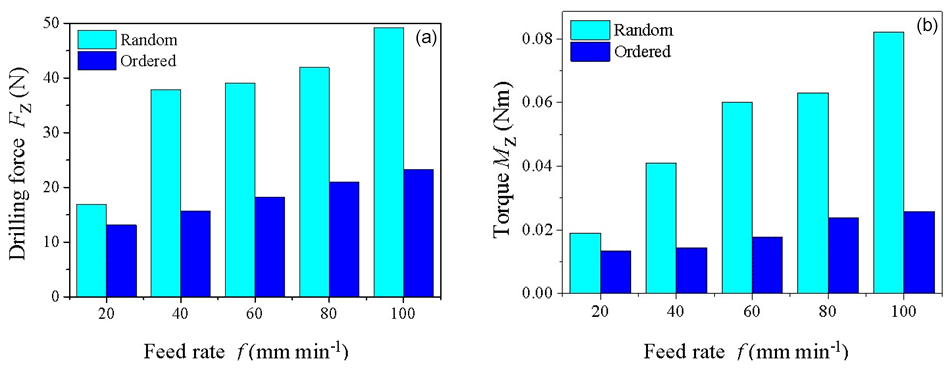
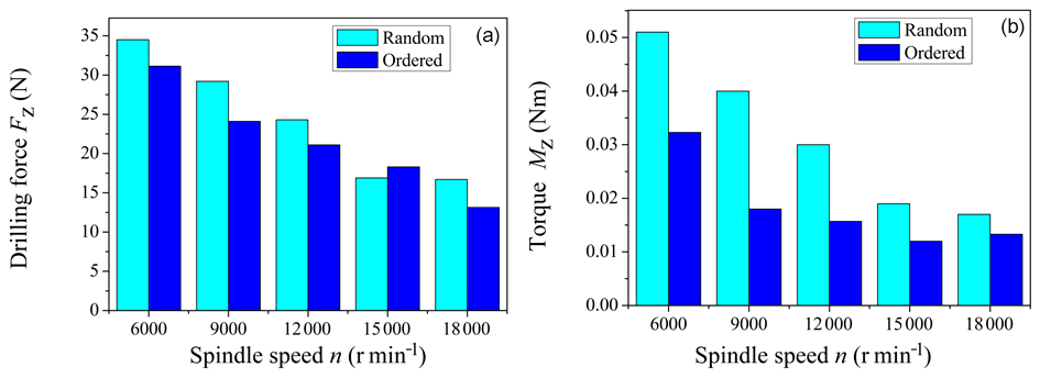
Figure 4 shows the feed rate influence on the drilling force and torque in the ordered and random abrasive distribution tests, respectively, where f= 20 mm min−1. The drilling force and torque increased with the increase in feed rate with both the ordered and random abrasive distributions. However, the drilling force and torque of the ordered drill were lower than those of the random drill. The drilling force and torque values of the drill with the ordered abrasive distribution were lower than those of the drill with the random abrasive distribution by 9.77 %–21.36 % and 21.76 %–36.67 %, respectively. Figure 5 presents the influence of the spindle speed on the drilling force and torque of the drills with the ordered and random abrasive distributions when n=15 000 r min−1. It can be seen from Fig. 5 that, with the increase in the spindle speed, the drilling force and torque gradually decreased.
3.2 Tear defect of the hole exit
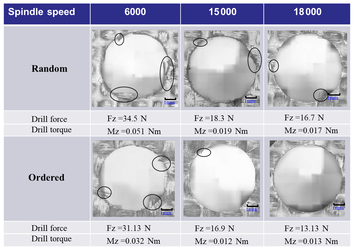
The tearing and burr defects in drilling this composite material have always been a difficult problem in the industry. Figure 6 shows the tear and burr defects at the borehole exit. It can be seen that under different processing parameters, the surface quality of the drilling outlet greatly varied. For the feed rate of 20 mm min−1 and spindle speed of 6000 r min−1, the drilling force for the drills with the ordered and random abrasive distributions was 31.13 and 34.5∘ N, respectively, and the torque was 0.032 and 0.051 Nm, respectively. The holes produced by the drill with the ordered abrasive distribution under these processing conditions were partially torn at the exit, and their quality was better than in the case of the drill with the random abrasive distribution. When the spindle speed was increased to 15 000 r min−1, the drilling force and torque of the drills with the ordered and random abrasive distributions obviously decreased, so the outlet quality of the drill hole could be improved. However, when the feed rate was increased to 80 mm min−1, even at a spindle speed of 15 000 r min−1, the exit quality of the drill hole of the drill with the random abrasive distribution was found to significantly deteriorate again.
From Fig. 6, it can be seen that the drill with the ordered abrasive distribution could produce better hole exits than those of the drill with the random abrasive distribution under the same processing conditions. Also, the tearing and burrs of the drill with the ordered abrasive distribution were much lower than those of the drill with the random abrasive distribution. Additionally, the random abrasive distribution could only produce high-quality exit holes at a specific high spindle speed and a low feed rate.
3.3 Morphology of the inner wall of the hole
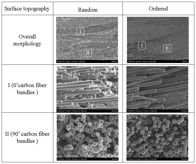
Figure 7 illustrates the SEM micro-morphology of the inner hole wall drilled at a spindle speed of 18 000 r min−1 and a feed rate of 20 mm min−1. For each drilled surface of the inner wall of the hole, SEM images of 0 and 90∘ fiber bundles are presented in Fig. 7. It can be seen that, compared with the random abrasive distribution, the surface quality of the inner hole wall for the drill with the ordered abrasive distribution was smoother under the same operating conditions. Since the drill with the ordered diamond abrasive distribution has a certain uniform chip-holding space, the carbon fibers were less fragmented. In fact, the drilling process was a process of material destruction. With the continuous drilling of the workpiece by abrasive particles, the composite was damaged by interface debonding, fiber fracture, and matrix cracking. This can be attributed to the fact that in the process of drilling, the damage to the matrix and fiber is not the same due to the different mechanical properties of the matrix and fiber. Figure 7 shows that the fibers underwent fracture and cracking under the drilling force and torque. Also, the 0∘ fiber bundles appeared to separate between the fibers and the fracture, and the ends of the 90∘ fiber bundles were broken and pressed into the matrix by the abrasive grains.
3.4 Drilling debris
Figure 8a and bare abrasive debris enlargement diagrams were collected for the drills with the ordered and random abrasive distributions under the same technological parameters, respectively. From Fig. 8, it can be seen that the debris is mainly composed of fine carbon powder, carbon fiber fragments of various lengths, and broken silicon carbide particles. Regarding the size, most of the debris is basically similar. As for the shape, it is basically a cluster of carbon powder; however, it is also mixed with some different particle sizes of silicon carbide. In particular, the carbon fiber fragments in the drilled debris with the random diamond abrasive distribution were longer and more numerous than those of the drilled debris with the ordered diamond abrasive distribution, and the size of the carbon fibers was more uniform for the drill with the ordered diamond abrasive distribution. Also, the morphology of the debris reflected the stress state of the carbon fiber and SiC matrix during the fracture process. These morphologies and stress states are directly related to the material properties, processing parameters, and abrasive properties.
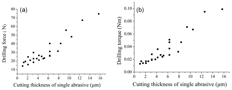
Figure 11Influence of the single abrasive cutting thickness on the drilling force and torque.
-
Effect of the cutting thickness of the single diamond abrasive on the exit quality and hole wall morphology.
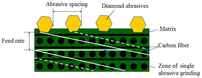
Based on the above observations of the hole's exit quality and the morphology of the hole wall, the tearing defects were the main defects in the exit of the 2D Cf∕C–SiC composites during the drilling process. When the workpiece contacted the abrasive particles, the material was extruded, resulting in elastic deformation. Also, the deformation increased with the increase in the load. When the elastic limit was exceeded, the contact stress between the abrasive particles and the material was similar to plastic deformation, leaving irrecoverable marks on the material. At the front end of the abrasive particles, the material was bulged and damaged. When the material broke at the edge, it broke away from the body and formed a tear. Figure 9 shows the trajectory of the diamond abrasives, and Fig. 10 presents the trajectory of the expansion diagram. The trajectory of each diamond abrasive is a cylindrical spiral, and the helical pitch is affected by the feed speed. When setting the same processing parameters, there was no difference in the trajectory of the single abrasive particles between the two sets of drills. However, the main difference between them is that the distance between the abrasive grains is different, which affects the shape and size of the cutting thickness of each single abrasive.
From Fig. 10, it can be seen that the cutting thickness of a single abrasive can be deduced from the graphical geometric relationship as follows:
where h denotes the cutting thickness of the single abrasive, s denotes the abrasive spacing, f is the feed rate, vs is the cutting speed, n is the spindle speed, and D is the drill diameter.
It can be seen from the formula that the cutting thickness h of a single diamond abrasive grain is proportional to s and f in the drilling hole with the diamond core drill. If the distance between the abrasives and the feed speed is increased, the cutting thickness of each single abrasive would directly increase. Consequently, the drilling force and torque would also increase. Figure 11 shows the influence of each single abrasive cutting thickness on the drilling force and torque. With the increase in the single abrasive cutting thickness, the drilling force and the torque increase accordingly. The ordered diamond abrasive distribution can control the distance between the abrasives well, thus controlling the cutting thickness of each single abrasive and further improving the drilling force and torque.
-
Effect of the cutting thickness of each single abrasive on the surface quality of the hole wall
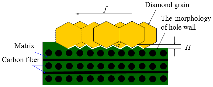
Since the relative positions of the abrasives are not exactly the same, with the movement of an abrasive on the workpiece, a certain residual material remains on the hole by the abrasive. Also, the height of the residual material directly affects the surface quality of the hole wall.
Before brazing the abrasives, they were carefully screened. The grain size was nearly the same, and the contour was even better. In this case, although the relative position distribution of the diamond abrasives is regular, the areas contained between every two adjacent abrasives are different, which leads to unresected material left on the hole wall. The residual height is the basis for evaluating the surface roughness of the inner wall of the hole, as shown in Fig. 12, where the residual material height H between the abrasives is related to the roughness Raof the inner wall of the hole. A larger H value signifies a larger Ra. The calculation method of H is as follows.
The residual width of the hole wall material is
where s is the distance between two abrasive grains, f is the feed speed, n is the spindle speed, p is the feed per turn of the tool, and α is the angle between the abrasive grains.
It can be seen from the formula that the height of the residual material can be reduced and that the surface quality of the hole wall can be improved by reducing the distance between the abrasive grains, decreasing the feed speed, or increasing the spindle speed. However, the cutting thickness of each single abrasive also affects the residual height of the cutting thickness. As the cutting thickness decreases, the residual material height decreases, the micro-height difference of the hole wall surface decreases, and the surface quality of the hole wall can be improved.
In this study, two kinds of brazed diamond core drills with ordered and random diamond abrasive distributions were compared through drilling experiments, and the following conclusions were drawn.
-
Drilling with an ordered abrasive distribution reduces the damage defects in the hole entrance and hole exit. The main effect mechanism of the drill with the ordered abrasive distribution is the cutting thickness of each single abrasive. If this thickness is reasonably controlled, the drilling force can be controlled, and the surface quality can be improved to a certain extent.
-
The process parameters have a significant influence on the drilling force, torque, and hole quality. The high spindle speed and low feed rate are effective in improving the drilled hole quality.
-
The tearing and burr defects in the hole exit and inner hole wall have a strong relationship with the cutting direction and fiber orientation.
All data included in this study are available upon request by contact with the corresponding author.
QL made substantial contributions to the conception and design, the acquisition, the analysis, and the interpretation of data for the work. She also drafted the work or revised it critically for important intellectual content. GQH supervised and structured the process of the paper. YCX checked the writing and language.
The authors declare that they have no conflict of interest.
The authors appreciate financial supports from the National Natural Science Foundation of China (grant nos. 51235004 and 51575198), the Program for Innovative Research Team in Science and Technology at Fujian Province University (grant no. JA12003), and the University Research Initiation Fund (grant no. GY-Z19115).
This research has been supported by the National Natural Science Foundation of China (grant nos. 51235004 and 51575198), the Innovative Research Team in Science and Technology at Fujian Province University (grant no. JA12003), and the University Research Initiation Fund (grant no. GY-Z19115).
This paper was edited by Jeong Hoon Ko and reviewed by Dennis Neo and two anonymous referees.
Cao, X. Y., Lin, B., and Zhang, X. F.: A study on grinding surface waviness of woven ceramic matrix composites, Appl. Surf. Sci., 270, 503–512, https://doi.org/10.1016/j.apsusc.2013.01.069, 2013.
Ding, K., Fu, Y. C., Su, H. H., Chen, Y., Yu, X. Z., and Ding, G. Z.: Experimental studies on drilling tool load and machining quality of C/SiC composites in rotary ultrasonic machining, J. Mater. Process. Tech., 214, 2900–2907, https://doi.org/10.1016/j.jmatprotec.2014.06.015, 2014.
Ding, K., Fu, Y. C., Su, H. H., and Cui, F. F.: Study on surface/subsurface breakage in ultrasonic assisted grinding of C/SiC composites, Int. J. Adv. Manuf. Tech., 91, 3095–3105, https://doi.org/10.1007/s00170-017-0012-z, 2017.
Feng, P. F., Wang, J. J., Zhang, J. F., and Zheng, J. Z.: Drilling induced tearing defects in rotary ultrasonic machining of C/SiC composites, Ceram. Int., 43, 791–799, https://doi.org/10.1016/j.ceramint.2016.10.010, 2017.
Liu, D. F., Tang, Y. J., and Cong, W. L.: A review of mechanical drilling for composite laminates, Compos. Struct., 94, 1265–1279, https://doi.org/10.1016/j.compstruct.2011.11.024, 2012.
Liu, Q., Huang, G. Q., Fang, C. F., Cui, C. C., and Xu, X. P.: Experimental investigations on grinding characteristics and removal mechanisms of 2D–Cf/C-SiC composites based on reinforced fiber orientations, Ceram. Int., 43, 15266–15274, https://doi.org/10.1016/j.ceramint.2017.08.064, 2017.
Liu, Q., Huang, G. Q., Xu, X. P., Fang, C. F., and Cui, C. C.: Influence of grinding fiber angles on grinding of the 2D-Cf/C-SiC composites, Ceram. Int., 44, 12774–12782, https://doi.org/10.1016/j.ceramint.2018.04.083, 2018.
Mei, H., Wang, H. W., Ding, H., Zhang, N., Wang, Y. T., and Xiao, S. S.: Strength and toughness improvement in a C/SiC composite reinforced with slurry-prone SiC whiskers, Ceram. Int., 40, 14099–14104, https://doi.org/10.1016/j.ceramint.2014.05.141, 2014. Singh, J. P., Bansal, N. P., and Takashi, G.: Processing and Properties of Advanced Ceramics and Composites IV, Ceram. Trans., 234, 195–210, https://doi.org/10.1002/9781118491867, 2012.
Tawakoli, T. and Azarhoushang, B.: Intermittent grinding of ceramic matrix composites (CMCs) utilizing a developed segmented wheel, Int. Mach. Tool. Manu., 51, 112–119, https://doi.org/10.1016/j.ijmachtools.2010.11.002, 2011.
Wang, Y. and Wu, H. Z.: Microstructure of friction surface developed on carbon fiber reinforced carbon–silicon carbide (Cf/C–SiC), J. Eur. Ceram. Soc., 32, 3509–3519, https://doi.org/10.1016/j.jeurceramsoc.2012.03.039, 2012.
Wang, C. H., Zhang, L. T., Liu, Y. S., Cheng, G. H., Zhang, Q., and Hua, K.: Ultra-short pulse laser deep drilling of C/SiC composites in air, Appl. Phys. A.-Mater., 111, 1213–1219, https://doi.org/10.1007/s00339-012-7377-5, 2013.
Xing, Y. Q., Deng, J. X., Zhang, G. D., Wu, Z., and Wu, F. F.: Assessment in drilling of C/C-SiC composites using brazed diamond drills, J. Manuf. Process., 26, 31–43, https://doi.org/10.1016/j.jmapro.2017.01.006, 2017. Yu, H. J., Zhou, X. G., Zhang, W. H., Peng, X., and Zhang, C. R.: Mechanical behavior of SiCf/SiC composites with alternating PyC/SiC multilayer interphases, Mater. Des., 44, 320–324, https://doi.org/10.1016/j.matdes.2012.07.073, 2013.
Zhang, W. H., Cheng, L. F., Liu, Y. S., Zhang, L. T., Yang, W. B., and Zhou, S. T.: Fracture behaviors and mechanism of 2D C/SiC-BCx composite under tensile load, Mater. Sci. Eng. A., 530, 297–303, https://doi.org/10.1016/j.msea.2011.09.089, 2011.
Zhang, L. F., Ren, C. Z., Ji, C. H., Wang, Z. Q., and Chen, G.: Effect of fiber orientations on surface grinding process of unidirection C/SiC composites, Appl. Surf. Sci., 366, 424–431, https://doi.org/10.1016/j.apsusc.2016.01.142, 2016.